EP2422397B1 - Système de piles à combustible - Google Patents
Système de piles à combustible Download PDFInfo
- Publication number
- EP2422397B1 EP2422397B1 EP10715786.9A EP10715786A EP2422397B1 EP 2422397 B1 EP2422397 B1 EP 2422397B1 EP 10715786 A EP10715786 A EP 10715786A EP 2422397 B1 EP2422397 B1 EP 2422397B1
- Authority
- EP
- European Patent Office
- Prior art keywords
- fuel cell
- pressure
- unit
- fuel
- housing
- Prior art date
- Legal status (The legal status is an assumption and is not a legal conclusion. Google has not performed a legal analysis and makes no representation as to the accuracy of the status listed.)
- Active
Links
Images

Classifications
-
- H—ELECTRICITY
- H01—ELECTRIC ELEMENTS
- H01M—PROCESSES OR MEANS, e.g. BATTERIES, FOR THE DIRECT CONVERSION OF CHEMICAL ENERGY INTO ELECTRICAL ENERGY
- H01M8/00—Fuel cells; Manufacture thereof
- H01M8/02—Details
- H01M8/0202—Collectors; Separators, e.g. bipolar separators; Interconnectors
- H01M8/0258—Collectors; Separators, e.g. bipolar separators; Interconnectors characterised by the configuration of channels, e.g. by the flow field of the reactant or coolant
- H01M8/0263—Collectors; Separators, e.g. bipolar separators; Interconnectors characterised by the configuration of channels, e.g. by the flow field of the reactant or coolant having meandering or serpentine paths
-
- H—ELECTRICITY
- H01—ELECTRIC ELEMENTS
- H01M—PROCESSES OR MEANS, e.g. BATTERIES, FOR THE DIRECT CONVERSION OF CHEMICAL ENERGY INTO ELECTRICAL ENERGY
- H01M8/00—Fuel cells; Manufacture thereof
- H01M8/02—Details
- H01M8/0202—Collectors; Separators, e.g. bipolar separators; Interconnectors
- H01M8/0247—Collectors; Separators, e.g. bipolar separators; Interconnectors characterised by the form
-
- C—CHEMISTRY; METALLURGY
- C01—INORGANIC CHEMISTRY
- C01B—NON-METALLIC ELEMENTS; COMPOUNDS THEREOF; METALLOIDS OR COMPOUNDS THEREOF NOT COVERED BY SUBCLASS C01C
- C01B3/00—Hydrogen; Gaseous mixtures containing hydrogen; Separation of hydrogen from mixtures containing it; Purification of hydrogen; Reversible storage of hydrogen
- C01B3/02—Production of hydrogen; Production of gaseous mixtures containing hydrogen
-
- C—CHEMISTRY; METALLURGY
- C25—ELECTROLYTIC OR ELECTROPHORETIC PROCESSES; APPARATUS THEREFOR
- C25B—ELECTROLYTIC OR ELECTROPHORETIC PROCESSES FOR THE PRODUCTION OF COMPOUNDS OR NON-METALS; APPARATUS THEREFOR
- C25B9/00—Cells or assemblies of cells; Constructional parts of cells; Assemblies of constructional parts, e.g. electrode-diaphragm assemblies; Process-related cell features
- C25B9/60—Constructional parts of cells
- C25B9/65—Means for supplying current; Electrode connections; Electric inter-cell connections
-
- H—ELECTRICITY
- H01—ELECTRIC ELEMENTS
- H01M—PROCESSES OR MEANS, e.g. BATTERIES, FOR THE DIRECT CONVERSION OF CHEMICAL ENERGY INTO ELECTRICAL ENERGY
- H01M8/00—Fuel cells; Manufacture thereof
-
- H—ELECTRICITY
- H01—ELECTRIC ELEMENTS
- H01M—PROCESSES OR MEANS, e.g. BATTERIES, FOR THE DIRECT CONVERSION OF CHEMICAL ENERGY INTO ELECTRICAL ENERGY
- H01M8/00—Fuel cells; Manufacture thereof
- H01M8/02—Details
- H01M8/0202—Collectors; Separators, e.g. bipolar separators; Interconnectors
- H01M8/0258—Collectors; Separators, e.g. bipolar separators; Interconnectors characterised by the configuration of channels, e.g. by the flow field of the reactant or coolant
-
- H—ELECTRICITY
- H01—ELECTRIC ELEMENTS
- H01M—PROCESSES OR MEANS, e.g. BATTERIES, FOR THE DIRECT CONVERSION OF CHEMICAL ENERGY INTO ELECTRICAL ENERGY
- H01M8/00—Fuel cells; Manufacture thereof
- H01M8/02—Details
- H01M8/0271—Sealing or supporting means around electrodes, matrices or membranes
- H01M8/0273—Sealing or supporting means around electrodes, matrices or membranes with sealing or supporting means in the form of a frame
-
- H—ELECTRICITY
- H01—ELECTRIC ELEMENTS
- H01M—PROCESSES OR MEANS, e.g. BATTERIES, FOR THE DIRECT CONVERSION OF CHEMICAL ENERGY INTO ELECTRICAL ENERGY
- H01M8/00—Fuel cells; Manufacture thereof
- H01M8/02—Details
- H01M8/0271—Sealing or supporting means around electrodes, matrices or membranes
- H01M8/0276—Sealing means characterised by their form
-
- H—ELECTRICITY
- H01—ELECTRIC ELEMENTS
- H01M—PROCESSES OR MEANS, e.g. BATTERIES, FOR THE DIRECT CONVERSION OF CHEMICAL ENERGY INTO ELECTRICAL ENERGY
- H01M8/00—Fuel cells; Manufacture thereof
- H01M8/02—Details
- H01M8/0271—Sealing or supporting means around electrodes, matrices or membranes
- H01M8/028—Sealing means characterised by their material
- H01M8/0284—Organic resins; Organic polymers
-
- H—ELECTRICITY
- H01—ELECTRIC ELEMENTS
- H01M—PROCESSES OR MEANS, e.g. BATTERIES, FOR THE DIRECT CONVERSION OF CHEMICAL ENERGY INTO ELECTRICAL ENERGY
- H01M8/00—Fuel cells; Manufacture thereof
- H01M8/02—Details
- H01M8/0271—Sealing or supporting means around electrodes, matrices or membranes
- H01M8/0286—Processes for forming seals
-
- H—ELECTRICITY
- H01—ELECTRIC ELEMENTS
- H01M—PROCESSES OR MEANS, e.g. BATTERIES, FOR THE DIRECT CONVERSION OF CHEMICAL ENERGY INTO ELECTRICAL ENERGY
- H01M8/00—Fuel cells; Manufacture thereof
- H01M8/02—Details
- H01M8/0289—Means for holding the electrolyte
-
- H—ELECTRICITY
- H01—ELECTRIC ELEMENTS
- H01M—PROCESSES OR MEANS, e.g. BATTERIES, FOR THE DIRECT CONVERSION OF CHEMICAL ENERGY INTO ELECTRICAL ENERGY
- H01M8/00—Fuel cells; Manufacture thereof
- H01M8/02—Details
- H01M8/0297—Arrangements for joining electrodes, reservoir layers, heat exchange units or bipolar separators to each other
-
- H—ELECTRICITY
- H01—ELECTRIC ELEMENTS
- H01M—PROCESSES OR MEANS, e.g. BATTERIES, FOR THE DIRECT CONVERSION OF CHEMICAL ENERGY INTO ELECTRICAL ENERGY
- H01M8/00—Fuel cells; Manufacture thereof
- H01M8/10—Fuel cells with solid electrolytes
- H01M2008/1095—Fuel cells with polymeric electrolytes
-
- H—ELECTRICITY
- H01—ELECTRIC ELEMENTS
- H01M—PROCESSES OR MEANS, e.g. BATTERIES, FOR THE DIRECT CONVERSION OF CHEMICAL ENERGY INTO ELECTRICAL ENERGY
- H01M8/00—Fuel cells; Manufacture thereof
- H01M8/02—Details
- H01M8/0202—Collectors; Separators, e.g. bipolar separators; Interconnectors
- H01M8/0204—Non-porous and characterised by the material
- H01M8/0206—Metals or alloys
-
- H—ELECTRICITY
- H01—ELECTRIC ELEMENTS
- H01M—PROCESSES OR MEANS, e.g. BATTERIES, FOR THE DIRECT CONVERSION OF CHEMICAL ENERGY INTO ELECTRICAL ENERGY
- H01M8/00—Fuel cells; Manufacture thereof
- H01M8/02—Details
- H01M8/0202—Collectors; Separators, e.g. bipolar separators; Interconnectors
- H01M8/0204—Non-porous and characterised by the material
- H01M8/0213—Gas-impermeable carbon-containing materials
-
- H—ELECTRICITY
- H01—ELECTRIC ELEMENTS
- H01M—PROCESSES OR MEANS, e.g. BATTERIES, FOR THE DIRECT CONVERSION OF CHEMICAL ENERGY INTO ELECTRICAL ENERGY
- H01M8/00—Fuel cells; Manufacture thereof
- H01M8/02—Details
- H01M8/0202—Collectors; Separators, e.g. bipolar separators; Interconnectors
- H01M8/0204—Non-porous and characterised by the material
- H01M8/0223—Composites
- H01M8/0228—Composites in the form of layered or coated products
-
- H—ELECTRICITY
- H01—ELECTRIC ELEMENTS
- H01M—PROCESSES OR MEANS, e.g. BATTERIES, FOR THE DIRECT CONVERSION OF CHEMICAL ENERGY INTO ELECTRICAL ENERGY
- H01M8/00—Fuel cells; Manufacture thereof
- H01M8/10—Fuel cells with solid electrolytes
- H01M8/1009—Fuel cells with solid electrolytes with one of the reactants being liquid, solid or liquid-charged
- H01M8/1011—Direct alcohol fuel cells [DAFC], e.g. direct methanol fuel cells [DMFC]
-
- Y—GENERAL TAGGING OF NEW TECHNOLOGICAL DEVELOPMENTS; GENERAL TAGGING OF CROSS-SECTIONAL TECHNOLOGIES SPANNING OVER SEVERAL SECTIONS OF THE IPC; TECHNICAL SUBJECTS COVERED BY FORMER USPC CROSS-REFERENCE ART COLLECTIONS [XRACs] AND DIGESTS
- Y02—TECHNOLOGIES OR APPLICATIONS FOR MITIGATION OR ADAPTATION AGAINST CLIMATE CHANGE
- Y02E—REDUCTION OF GREENHOUSE GAS [GHG] EMISSIONS, RELATED TO ENERGY GENERATION, TRANSMISSION OR DISTRIBUTION
- Y02E60/00—Enabling technologies; Technologies with a potential or indirect contribution to GHG emissions mitigation
- Y02E60/30—Hydrogen technology
- Y02E60/50—Fuel cells
Definitions
- the invention relates to a fuel cell system, in particular a modular fuel cell system with a supply unit, a control and regulation unit and a fuel cell unit.
- Fuel cells are used to convert chemical reaction energy into electrical energy.
- a fuel cell to a fuel and an oxidizing agent are supplied continuously. In the reaction of the two, a stream of electrons and thus electrical energy is generated.
- a conventional single fuel cell typically provides a low voltage, typically less than or equal to 1.2 volts, and a comparatively high current of up to about 3A / cm 2 , with the area referenced to the size of active areas in a fuel cell. Since in modern membrane fuel cells the size of the active areas of the membrane-electrode unit is slightly more than 100 cm 2 , a single such cell can deliver a current of up to 300 A with a maximum DC voltage of 1.2V. Such high currents with low voltage are technically difficult to use.
- the voltage generated by a single cell is therefore too low for many common applications today.
- in conventional fuel cell systems often several cells are connected in series, so that the respective voltages of the cells add up.
- the electrically interconnected fuel cells are often also connected in series with respect to the supply of the fuel and the oxidant, so that the fuel discharge of a cell is the fuel supply of the series-connected next fuel cell.
- the fuel cells may be connected in series with respect to the supply of oxidant.
- Conventional fuel cells usually have a flat, planar shape with a quadrangular base.
- a series connection with a plurality of fuel cells is often designed as a so-called "stack", ie as a stack.
- the flat fuel cells are stacked on top of each other, so that a cuboid with the base of a fuel cell and the height corresponding to the Number of stacked cells and thus gives a manageable geometric shape.
- the fuel cells connected in such a stack are firmly connected to each other.
- the electrical connections and the supply and discharge of the fuel the oxidizing agent and the discharge of the reaction product must be solved.
- a modular fuel cell system is in the DE 10 2006 048 860 A1 disclosed.
- the system described has a module base unit with at least two recesses arranged in a planar manner for the positive reception of fuel cells, so that the fuel cells in the module base unit are arranged flat next to one another. This results in a planar, planar design of the fuel cell system.
- the flat design of the system described requires a considerable amount of space.
- the DE 195 17052 C1 discloses a fuel cell system comprising a fuel cell stack comprising a plurality of stacked fuel cells. About a pressure gas, a contact pressure can be exerted on the uppermost fuel cell of the fuel cell stack. This leads, in particular for the fuel cells located in the middle of the stack, to an uneven distribution of the contact pressure. The object is therefore to propose a fuel cell system in which the contact pressure is equal at all points.
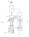
- FIG. 1 A block diagram of a fuel cell system 100 shown includes a central control and regulation unit 110, a supply unit 120, a fuel cell unit 130, optionally a voltage converter 140 and optionally a pressure holding device 150.
- the supply unit 120 has all the facilities in order, on the one hand, to stockpile the fuel and the oxidizing agent, that is to say the consumables required for operating the system, and to supply them to the fuel cell unit 130.
- These devices include reservoirs 121, 122 for fuel and the oxidizer, respectively, and controllers 123 for controllably supplying the fuel or oxidizer to the fuel cell unit, with the reservoirs 121, 122 being arranged with the controllers 123 in a common housing or outside such housing can.
- the control devices 123 are connected on the one hand to the storage containers, on the other hand to the fuel cell unit and to the central control and regulation unit 110.
- the controllers may be pumps, such as a hydrogen and / or an air pump, and controllable valves and pressure regulators for controlling the fuel flow or oxidant flow, such that the fuel and oxidant have an over-atmosphere pressure of 0.5 bar be fed to 1.5 bar of the fuel cell unit.
- the supply unit 120 has devices for receiving unused fuel or unconsumed oxidant. These Received, unused supplies can then be the appropriate storage containers 121, 122 or the fuel cell unit 130 fed again.
- the fuel cell system 100 has a pressure holding device 150 for the controlled generation and maintenance of an overpressure in a housing of the fuel cell unit 130.
- the pressure holding device may be connected to the control and regulation unit 110.
- the pressure holding device may have a reservoir for storing the pressure-generating medium and a heating or cooling device for heating or cooling of the medium.
- the optional pressure holding device 150 generates an overpressure relative to the ambient atmospheric pressure by means of the medium in the housing of the fuel cell unit, wherein the overpressure can be between 5 bar and 20 bar, preferably between 10 bar and 15 bar, so that the pressure is higher than the internal pressure is a fuel cell arranged in the housing of the fuel cell unit, which is determined by the fuel or the oxidant pressure.
- the medium used to generate and maintain the pressure may be a suitable gaseous or liquid heating or cooling medium.
- the medium can be heated or cooled by means of the heating or cooling device, so that the medium can be used in addition to the pressure generation at the same time for controlling the temperature in the housing of the fuel cell unit.
- connections of the pressure-retaining device 150 to the fuel cell unit 130 as well as to the control and regulation unit are preferably designed as a quick-change connection in each case.
- the control and regulation unit 110 is connected to the supply unit 120, to the fuel cell unit 130 as well as to the optional voltage converter 140 and the optional pressure holding device 150.
- the control and regulation unit has control and regulating devices for controlling the fuel cell system 100. This includes control and regulating devices for controlling the inflow of fuel and the inflow of oxidant to the fuel cell unit 130.
- the control and regulation devices of the unit 110 accordingly control the pumps, valves and pressure regulators contained in the supply unit 120, so that the fuel or the oxidizing agent is supplied to the fuel cells during operation of the fuel cell unit 130 in sufficient quantity and with suitable pressure.
- the supply of the control and regulation unit 110 with voltage or current takes place during operation of the fuel cell system 100 via the fuel cells, that is to say with the electrical energy generated by the system itself. This can be supplied to the control and regulation unit via the connection to the fuel cell unit or alternatively via the connection to the voltage converter 140.
- the control and regulating unit to an energy storage 111, via which the unit at the beginning of operation, so for example when switching on the fuel cell system, with electr. Energy is supplied.
- the energy storage 111 supplies sufficient energy to supply the devices within the control and regulation unit 110 and to supply the supply unit, as far as this is necessary for the commissioning of the system 100.
- the energy store 111 can preferably be rechargeable, so that the energy store can be recharged during operation of the system for subsequent commissioning.
- the energy store may be a rechargeable battery, that is to say an accumulator, or a capacitor of low self-discharge, for example so-called gold caps.
- control unit 110 may be one or more voltage converters 112, 113 for down-converting or boosting the voltage from the energy storage 111 or the voltage supplied by the fuel cell unit 130 or the voltage converter 140.
- the voltage transformers 112, 113 convert the voltage supplied to each into a voltage for supply the electronic elements in the control and regulation unit and for supplying, for example, the valves, pumps or pressure regulator in the supply unit 120 to.
- the control and regulating unit furthermore has electronic assemblies which receive a control parameter, for example from the fuel cell unit 130, the voltage converter 140 or the optional pressure holding device 150 and the supply unit 120, and determine according to a predetermined operation for controlling and regulating the supply unit, the fuel cell unit 130, the voltage converter 140 and the pressure holding device 150 necessary parameters and control the connected units accordingly.
- the control and regulating unit can be designed such that each of the fuel cells in the fuel cell unit can be separately monitored with regard to the operating parameters and can be controlled separately with regard to the supply of operating materials.
- control and regulating unit for this purpose has a microcontroller 114 and associated digital or analog input and output stages 115, 116, which adjust the signals supplied by connected units to the control and regulation unit 110 to levels, the microcontroller 114 can process these, or adapts the level supplied by the microcontroller to those for driving connected units.
- the fuel cell unit 130 is connected to the supply unit 120 for the supply and discharge of fuel or oxidant. These connections are designed so that they can be quickly and easily connected and disconnected, so that the fuel cell unit 130 can be disconnected from the supply unit and connected to it with as few hand movements as possible.
- the Line connections are preferably designed as a quick-change automatic connection, so that when a connection is disconnected, the flow is automatically stopped, the line is therefore closed. In the opposite case, such an automatic connection should automatically release the flow as soon as a connection to the corresponding counterpart is connected.
- the supply and discharge of the operating materials to or from a fuel cell unit can be combined in a single connection unit, preferably a quick-change connector unit with a locking mechanism, so that the connection or disconnection of a fuel cell unit 130 from a supply unit 120 by connecting or disconnecting This central connection can be made.
- a quick-change connector unit with a locking mechanism
- Such quick-change connections which typically include a quick-change coupling and a corresponding quick-change connector, are those which are separable and connectable without or with minimal use of tools.
- the electrical connections of a fuel cell unit 130 may in one embodiment also be designed as quick-change connections, so that they can be disconnected and connected quickly and easily.
- the electrical connections can be designed as a plug connection, so that the electrical connection or connection of a fuel cell unit to the control and regulation unit 110 is to separate the plugs by hand or to connect them to one another.
- all electrical connections are brought together in a single connector, so that a fuel cell unit can be electrically connected and disconnected by means of this one connector.
- all connections to and from the pressure-maintaining device 150 can be designed as quick-change connections.
- the fuel cell unit 130 may include one or more fuel cells 131.
- the fuel cells may be connected in parallel to increase the output voltage of the fuel cell unit electrically in series, or alternatively to increase the output current.
- the voltage generated by the fuel cell or the current of each cell can be led separately from the fuel cell unit and then separately fed to another functional unit, for example, the control unit for separately monitoring each fuel cell and the other the voltage converter, so that it controls the electrical interconnection of the voltages and currents of the fuel cell.
- the voltage generated by the at least one fuel cell 131 in the fuel cell unit 130 can optionally be supplied to a voltage converter 140, which performs a voltage conversion to a desired output voltage for operation of any connected consumer 160, so that the fuel cell system 100 has an output voltage adapted to the consumer 160 and / or provides an adjusted output current. Without the optional voltage converter 140, the load 160 is connected directly to a fuel cell unit.
- the voltage converter 140 is connected to the control and regulation unit 110 and transmits to it the values of the input voltage and current as well as the output voltage and current, so that the control and regulation unit 110, the system 100 corresponding to the consumer 160 preset, more desirable Supplied voltage and current parameters.
- the electrical connections of the voltage converter 140 both to the fuel cell unit 130 and to the control and regulation unit 110 are preferably designed such that the connections can be made and released quickly.
- all the connections to a connected unit 130 or 110 can be brought together in each case in a central connection unit, for example in each case in a central plug or alternatively in a common plug.
- a plurality of fuel cell units 130 may also be connected to one or more supply units 120, a control and regulation unit 120, as well as a voltage converter 140 and one or more pressure holding devices, so that through series and / or parallel connection of any number of fuel cell units can achieve any power generation that can be delivered by means of the voltage converter 140 with an arbitrary voltage and current to a consumer.
- a control and regulation unit 120 may also be connected to one or more supply units 120, a control and regulation unit 120, as well as a voltage converter 140 and one or more pressure holding devices, so that through series and / or parallel connection of any number of fuel cell units can achieve any power generation that can be delivered by means of the voltage converter 140 with an arbitrary voltage and current to a consumer.
- a voltage converter 140 may also be connected to one or more supply units 120, a control and regulation unit 120, as well as a voltage converter 140 and one or more pressure holding devices, so that through series and / or parallel connection of any number of fuel cell units can achieve any power generation that can be delivered by means of the voltage
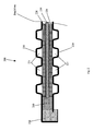
- FIG. 2 shows a schematic section through a fuel cell 200.
- such fuel cells can be used as a fuel cell 131 in fuel cell units 130.
- the fuel cells may be so-called low-temperature or high-temperature PEM fuel cells which contain hydrogen and oxygen as operating materials at max. 80 ° C or max. Burn 180 ° Celsius.
- a so-called direct methanol fuel cell a so-called DMFC (direct methanol fuel cell), can be used with the fuels methanol and oxygen.
- the fuel cell 200 has a substantially planar geometric shape.
- the cell 200 may have an edge length of about 100mm x 110mm and a thickness of a few millimeters, typically from 3mm to 10mm.
- the section through the cell shows a membrane-electrode unit 210, that is to say a so-called MEA (membrane electrode assembly), which is covered on both its large surfaces by gas diffusion layers 220, so-called GDLs (gas diffusion layers).
- the gas diffusion layers 220 are covered at their respective outer sides by pole plates 230, which serve to dissipate the generated electric current.
- the pole plates each have gas guide channels 231 on their surface adjoining the gas diffusion layer, through which the fuel or the oxidizing agent is passed.
- the gas guide channels of the pole plates thus form the so-called flowfield, ie the surfaces over which the fuel or the oxidant is supplied to the gas diffusion layers.
- the gas diffusion layers 220 and the membrane electrode assembly each adjoin an electrically insulating seal 240 at their edges, which prevents the lateral outflow of the fuel or oxidant from the gas diffusion layers and the MEA and electrically isolates the pole plates from each other.
- the gasket 240 is adjacent to an electrical insulator 250 that electrically insulates the pole plates 230 from each other.
- the channels for gas guidance can be arranged so that both the leading terminals and the dissipative terminals are guided to a common edge or narrow side of the fuel cell.
- the supply of the fuel cell with fuel and oxidant and the disposal of the resulting reaction products thus takes place at one edge, so a narrow side of the fuel cell instead.
- the associated connections of the fuel cell can thus also be arranged on a narrow side of the cell 200.
- the supply connections of the fuel cell can be arranged on opposite narrow sides.
- all supply lines can be arranged on a narrow side and all discharges on the opposite narrow side.
- the inlet and outlet for fuel on a narrow side and the inlet and outlet for oxidizing agent may be arranged on the opposite narrow side of the cell.
- the pole plates 230 may be formed of a single metallic material.
- a metal may be a stainless steel, in particular a corrosion-resistant stainless steel.
- the pole plates 230 may be formed of more than one metal, with the metals arranged in layers.
- Such a multi-layer structure may include, for example, an outer layer of nickel, the nickel layer forming the gas-bearing surface in the flowfield.
- On this first can be a layer of stainless steel, which causes the necessary mechanical strength of a pole plate.
- the stainless steel layer can be shaped and be structured so that it forms the gas-carrying channels - the flowfield -, wherein the flow field forming side of the pole plate layer of stainless steel is nickel-plated by conventional methods.
- a further metal layer On the outside of the pole plate can optionally be applied a further metal layer, which improves the conductivity of the pole plate.
- a copper layer can be applied to the outside of the pole plate, which thus does not come into contact with any of the consumables. In this way, with a multilayer structure of different metals, the desired mechanical properties, such as high strength, and the desired electrical properties can be achieved.
- the pole plates can be made of graphite or have a graphite layer.
- the pole plates of the fuel cell 200 may be connected to each other in various ways, the connection always being electrically insulating.
- the pole plates 230 are interconnected by crimping or crimping with insulation 250 therebetween.
- the crimping or folding can be interrupted at the points of the narrow sides, where connections for the supply and discharge lines are arranged.
- At the corners of a fuel cell can be made a fold with an additional corner envelope, so that in particular the corners contribute to the dimensional stability of the fuel cell.
- the fuel cell may be partially or completely surrounded by plastic.
- a partial enclosure of the fuel cell with plastic is thus designed as a frame, wherein the frame is formed along the edges of a fuel cell.
- the plastic envelope thus at least partially effects the dimensional stability of a fuel cell. Connections of the fuel cell for the supply and removal of fuel, oxidizing agent or reaction products may be passed through the plastic sheath or are formed in this, so that a connector is an integral part of the at least partially plastic sheath.
- the frame may further be designed such that it has an inlet and / or outlet for fuel or the oxidizing agent or a reaction product.
- a lead or lead from a narrow side to the opposite narrow side.
- all of its connections are arranged on a narrow side, so could for example fuel or the oxidant to the opposite narrow side and there are passed into the fuel cell, so that within the fuel cell, the flows of fuel and oxidant would be opposite; the fuel cell is thus operated according to the countercurrent principle.
- the pole plates 230 For the function of the fuel cell, it is necessary for the pole plates 230 to apply pressure to the gas diffusion layers and the membrane-electrode assembly. This pressure ensures on the one hand the tightness between adjacent gas guide channels, so that the gases flow only as intended in the gas ducts, but can seek no shortest connection between the respective inlet and outlet. On the other hand, the pressure causes the necessary electrical contact between the pole plates and the gas diffusion layers, so that the electrons produced during the reaction in the fuel cell reach the cathode.
- the pressure of the pole plates on the gas diffusion layers or membrane-electrode assembly can be effected by a crowning of the pole plates.
- the pole plates are produced in such a way that they have a concave curvature in the relaxed state, for example before the joining of a fuel cell. If, during the assembly of the fuel cell, the edges of the pole plates are connected to one another so that the edges of the pole plates are pulled together, the crowning of the pole plates causes the desired contact pressure.
- crowning can be effected in a conventional manner by suitable rolling.
- the contact pressure of the pole plates on the gas diffusion layers can be generated by means of clamps, in particular spring steel clamps, which are placed on a fuel cell from the outside.
- a fuel cell has flexible pole plates which exert no intrinsic pressure on the gas diffusion layers, but are so flexible that a pressure exerted on the pole plates from the outside causes a corresponding deformation and thus transmits the external pressure.
- One or both pole plates can have the corresponding flexibility.
- the necessary pressure for the operation of the fuel cell during operation of the cell is exerted externally on the pole plates.
- the cell can be operated in an overpressure container, wherein the overpressure, for example, a cooling liquid or gas causes the contact pressure of the pole plates.
- the fuel cell in the desired state so if the pole plates exert the desired pressure, are shed.
- the solidified potting material then causes the desired pressure from the outside on the pole plates, so that they generate the pressure on the gas diffusion layers.
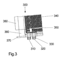
- FIG. 3 shows a section of a fuel cell 300 with a feed line 310 and a derivative 320, which are arranged on a narrow side of the fuel cell.
- a fuel cell may be used in a fuel cell unit 130 in one embodiment.
- the supply line 310 of the fuel cell fuel or oxidizing agent can be added or removed.
- the fuel cell 300 still has at least two further connections for the supply and discharge of fuel or oxidant. These further connections can be arranged on the same narrow side as those shown in the figure, so that all connections for the supply or discharge of operating materials can be arranged on a single narrow side of the fuel cell.
- the supply line 310 and the discharge 320 are designed here as a quick connector that allow easy insertion of the inlet and outlet into corresponding counterparts of such a quick connection.
- the inlet and outlet are each as pipe sections and each with at least one circumferential sealing ring 330 executed. The inlet and outlet thus each form a plug, which is plugged into a counterpart, the coupling.
- the pipe section may advantageously have a circumferential groove for fixing the sealing ring, which prevents displacement of the sealing ring during insertion into a coupling.
- the supply and discharge lines 310, 320 are connected to the gas-carrying passages 340 formed on the inner sides of the pole plates 350.
- the fuel cell 300 further comprises a frame 360 made of plastic. On the frame 360, a base 370 is further formed, which forms a base for the fuel cell 300 when inserting the plug 310, 320, ie the inlet and outlet.
- the fuel cell can have plug connections for producing the electrical connections, that is to say for tapping the generated current.
- the connectors can be arranged on the same narrow side of the fuel cell as the supply and discharge lines for supplying the cell with supplies.
- the connectors can be arranged between or next to the supply and discharge lines of the fuel cell, so that at the same time the electrical connections are made when inserting the inlet and outlet plugs 310, 320.
- the electrical connections of the fuel cell can be designed as contact lugs 380, which are led out of the fuel cell on a narrow side.
- the contact lugs of the anode or the cathode of the cell can be led out on opposite narrow sides of the cell or on the same narrow side next to each other and at a distance.
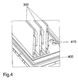
- FIG. 4 shows a plug-in board 400, a so-called backplane, a fuel cell unit 130.
- the plug-in plate has on one side a plurality of terminals 410 for connecting fuel cell inlets and outlets.
- the connections are essentially holes in the plate, which open into inlet and outlet channels in the plug-in plate. These supply and discharge channels can be connected to a supply unit 120.
- the couplings are designed so that they allow a media flow only when a plug is completely inserted into a coupling.
- the cross section of the inlet or outlet is accordingly only opened when a plug is plugged into the coupling.
- the inlet and outlet channels can be arranged in various ways in the plug-in plate 400.
- all supply lines can each be routed to a central supply line and all discharges to a corresponding central discharge line, so that the fuel cells are connected in parallel in terms of supply and disposal.
- the inlets and outlets may be looped through the cells so that they are connected in series for supply and disposal, the couplings being configured and interconnected so that a clutch will pass the flow if no fuel cell enters the clutch is plugged in.
- a fuel cell, which is inserted behind an empty slot in Troffenmanniques is accordingly connected to the central supply and discharge lines.
- the supply and discharge lines within the plug-in plate are designed in any case, the plug-in plate for the supply and discharge of fuel, oxidizing agent and reaction products each having a central port. Inside the plug-in board 400, the supply and discharge lines ensure that each fuel cell plugged into the plug-in board is supplied with the operating materials independently of other fuel cells and disposed of accordingly.
- the supply and discharge channels for each fuel cell are led separately to the connection for the supply unit, so that each fuel cell is connected separately to the supply unit.
- the supply unit and the control unit are accordingly configured so that the flow of the fuels for each fuel cell in the fuel cell unit is separately controllable.
- the plug-in board 400 may further comprise electrical connections for establishing the electrical connections of the fuel cells.
- the plug-in plate for this purpose have electrical plug-in connections in the plug-in plate, so that at the same time the electrical connections are made when plugging in the plug for the supply and discharge of fuel or oxidant.
- the electrical connections can be arranged next to or between the couplings for the supply and discharge lines.
- the electrical connections of each fuel cell can preferably be led out of the fuel cell unit separately, for example via separate contacts within a central plug, so that the generated voltage or the current of each cell is separate from the control and regulation unit 110 or to the optional one Voltage converter 140 are guided.
- the plug-in plate can have at least one connection via which a further medium can be supplied, so that an internal pressure can be applied to a housing of a fuel cell unit by means of the medium.
- the plug-in plate can have a further connection, so that the medium can flow through the housing.
- the medium can be a heating or cooling medium.
- the connections can be designed as quick-change connections.
- the plug-in plate can thus have a multiplicity of connections, in particular pluggable connections, for connecting and, in particular, plugging in a multiplicity of essentially planar fuel cells. Accordingly, the connections are preferably arranged in parallel rows, wherein a fuel cell can be plugged into a series of connections or plug-in connections, whereby all the electrical and supply connections of the fuel cell are produced by this insertion.
- the described properties of the plug-in board can be arranged on any side of the housing, for example as a housing bottom.
- FIG. 5 shows an embodiment of a housing 500 of a fuel cell unit, wherein in the figure, a closing cover plate is not shown.
- a fuel cell unit may be made of a fuel cell unit 130 Fig. 1 correspond.
- the housing 500 has a bottom plate 510, which is a plug-in plate 400 from Fig. 4 may correspond, and side walls 520 and a - not shown in the figure - cover plate.
- the fuel cell unit has a closed housing.
- the housing 500 may receive one or more fuel cells 300, which may be juxtaposed similar to a stack in the housing. Thus, the fuel cells can be plugged into one of their narrow sides or connections on this narrow side in corresponding connections in the bottom plate 510
- the housing is gas-tight and pressure-resistant. This can be effected in a conventional manner by seals 530, 531 between bottom plate and side walls and between side walls and cover plate and suitable fittings.
- a wall of the housing in particular a side wall or a plurality of side walls 520, have means for receiving and electrically contacting electrical contact lugs 380, the devices being arranged to match the arrangement of the contact lugs on the fuel cells.
- the devices can be arranged on opposite side walls of the housing, so that they also effect a mechanical fixation of the fuel cells in the housing.
- the housing of the fuel cell unit 500 can have connections for the supply and discharge of a gaseous or liquid heating or cooling medium, via which the heating or cooling medium can be passed through the housing.
- the heating or cooling medium with an overpressure so compared to the surrounding operating atmosphere increased pressure, are passed through the housing.
- the housing may be connected to the supply or discharge of the heating or cooling medium with a supply unit 120 described above, which provides the heating or cooling medium. Accordingly, the supply and discharge for the heating or cooling medium are connected to the supply unit 120, wherein the connection can be produced in particular via quick-release fasteners.
- the heating or cooling medium is passed through the housing 500 of the fuel cell unit with an overpressure, this overpressure causing a contact pressure of the pole plates on the gas diffusion layers and the membrane electrode assembly in the fuel cells. Since such a contact pressure of the pole plates is only effected when, on the one hand, the external pressure on the fuel cell is higher than its internal pressure, the heating or cooling medium is passed through the housing 500 at a pressure which is higher than the fuel and oxidant pressure.
- the fuel cells are formed so that they are slightly deformable, so that the pole plates yield to the external pressure acting on the fuel cell and thus generate a contact pressure on the gas diffusion layers or the membrane electrode assembly.
- the housing 500 of the fuel cell unit preferably has quick-change couplings, which allow a connection and disconnection of both the power and the resource supply and -ableititch in a simple and fast manner.
- the connections to a Supply unit can be produced in one embodiment via flexible lines, in particular flexible pressure hoses.
- the fuel cell system 100 thus makes possible a modular construction in which both the supply unit, the fuel cell unit, the control unit and the optional voltage converter unit can be connected to each other in a modular manner. Furthermore, the fuel cell unit is designed so that individual fuel cells can be used as modules quickly and without much effort in a housing of a fuel cell unit or removed.
- the modular design of the fuel cell system thus allows flexible adaptation of the system to a desired output power. Furthermore, for example, in the case of defects, the affected units or even fuel cells can be removed from the system or replaced.
- the system is therefore particularly suitable for use in mobile devices or, for example, for high-availability applications such as uninterruptible power supplies. Furthermore, the system can be used in inserts, for example, of cabinets.
Landscapes
- Chemical & Material Sciences (AREA)
- Engineering & Computer Science (AREA)
- Electrochemistry (AREA)
- Chemical Kinetics & Catalysis (AREA)
- Sustainable Development (AREA)
- Sustainable Energy (AREA)
- Life Sciences & Earth Sciences (AREA)
- Manufacturing & Machinery (AREA)
- General Chemical & Material Sciences (AREA)
- Organic Chemistry (AREA)
- Materials Engineering (AREA)
- Metallurgy (AREA)
- Combustion & Propulsion (AREA)
- Inorganic Chemistry (AREA)
- Fuel Cell (AREA)
Claims (10)
- Système de pile à combustible (100) comprenant- au moins une cellule à combustible (131) mince, plane, la cellule à combustible (131, 200) présentant une flexibilité suffisante pour la transmission au moins partielle d'une pression extérieure à une couche de diffusion de gaz (220) et une unité membrane-électrode (210), et- un boîtier (500) fermé, résistant à la pression, destiné à recevoir ladite au moins une cellule à combustible (131, 200) et un fluide liquide ou gazeux, la cellule à combustible (131, 200) étant entourée par ledit fluide au moins sur ses deux grands côtés opposés, respectivement sur toute leur surface, et comprenant en outre un dispositif de maintien de pression (150) pour produire et maintenir une surpression dans le boîtier (500).
- Système de pile à combustible selon la revendication 1, comprenant en outre une unité de commande et de régulation (110) reliée au dispositif de maintien de pression (150), pour commander et réguler la surpression.
- Système de pile à combustible selon l'une des revendications 1 ou 2, comprenant en outre un réservoir pour le stockage dudit fluide.
- Système de pile à combustible selon l'une des revendications 1 ou 2, comprenant en outre un dispositif de chauffage ou de refroidissement pour échauffer ou refroidir ledit fluide.
- Système de pile à combustible selon la revendication 3, comprenant en outre un dispositif pour produire une pression intérieure dans le boîtier.
- Procédé pour faire fonctionner un système de pile à combustible (100), qui comprend au moins un boîtier (500) résistant à la pression, destiné à recevoir au moins une cellule à combustible (131, 200) et un fluide liquide ou gazeux, la cellule à combustible étant entourée par ledit fluide au moins sur ses deux grands côtés opposés, respectivement sur toute leur surface, et le fluide liquide ou gazeux étant soumis à une pression dans le boîtier, de manière à produire une déformation élastique de la cellule à combustible (131, 200) pour augmenter la pression d'application d'une plaque polaire (230) sur une couche de diffusion de gaz (220) et une unité membrane-électrode (210).
- Procédé selon la revendication 6, dans lequel le fluide liquide ou gazeux est un fluide de chauffage ou de réfrigération, et s'écoule à travers le boîtier (500).
- Procédé selon la revendication 6, dans lequel le système de pile à combustible (100) comprend une unité de commande et de régulation (110) reliée à un dispositif de maintien de pression (150), pour commander et réguler la surpression.
- Procédé selon l'une des revendications 6 ou 8, dans lequel le système de pile à combustible (100) comprend en outre un réservoir pour le stockage dudit fluide.
- Procédé selon l'une des revendications 6 ou 8, dans lequel le système de pile à combustible (100) comprend en outre un dispositif de chauffage ou de refroidissement pour échauffer ou refroidir ledit fluide.
Applications Claiming Priority (2)
| Application Number | Priority Date | Filing Date | Title |
|---|---|---|---|
| DE102009017779A DE102009017779A1 (de) | 2009-04-20 | 2009-04-20 | Modulares Brennstoffzellensystem |
| PCT/EP2010/055012 WO2010121955A2 (fr) | 2009-04-20 | 2010-04-16 | Système modulaire de piles à combustible |
Publications (2)
| Publication Number | Publication Date |
|---|---|
| EP2422397A2 EP2422397A2 (fr) | 2012-02-29 |
| EP2422397B1 true EP2422397B1 (fr) | 2013-06-12 |
Family
ID=42262398
Family Applications (3)
| Application Number | Title | Priority Date | Filing Date |
|---|---|---|---|
| EP09169525A Withdrawn EP2244325A3 (fr) | 2009-04-20 | 2009-09-04 | Matériau pour la formation d'une couche de protection, procédé pour la préparation du matériau et PDP comprenant la couche de protection |
| EP09169517.1A Not-in-force EP2244324B1 (fr) | 2009-04-20 | 2009-09-04 | Plaque bombée du distributeur de Gaz |
| EP10715786.9A Active EP2422397B1 (fr) | 2009-04-20 | 2010-04-16 | Système de piles à combustible |
Family Applications Before (2)
| Application Number | Title | Priority Date | Filing Date |
|---|---|---|---|
| EP09169525A Withdrawn EP2244325A3 (fr) | 2009-04-20 | 2009-09-04 | Matériau pour la formation d'une couche de protection, procédé pour la préparation du matériau et PDP comprenant la couche de protection |
| EP09169517.1A Not-in-force EP2244324B1 (fr) | 2009-04-20 | 2009-09-04 | Plaque bombée du distributeur de Gaz |
Country Status (3)
| Country | Link |
|---|---|
| EP (3) | EP2244325A3 (fr) |
| DE (1) | DE102009017779A1 (fr) |
| WO (1) | WO2010121955A2 (fr) |
Families Citing this family (6)
| Publication number | Priority date | Publication date | Assignee | Title |
|---|---|---|---|---|
| DE102010028961A1 (de) * | 2010-05-12 | 2011-11-17 | Trumpf Werkzeugmaschinen Gmbh + Co. Kg | Modulares Brennstoffzellensystem |
| DE102010024318A1 (de) * | 2010-06-18 | 2011-12-22 | Imago-Edv-Systems Gmbh | Modular aufgebautes Batteriegehäuse bzw. -Halterung mit dazugehörigem Lade-/Kontroll und Managementmodul |
| DE102012018243A1 (de) | 2012-09-17 | 2014-03-20 | Propuls Gmbh | Verfahren und System zum Betreiben eines Elektrolyseurs |
| DE102014221976A1 (de) * | 2014-10-28 | 2016-04-28 | Bayerische Motoren Werke Aktiengesellschaft | Brennstoffzellensystem und Betriebsverfahren eines Brennstoffzellensystems |
| DE102018211408A1 (de) * | 2018-07-10 | 2020-01-16 | Robert Bosch Gmbh | Brennstoffzellensystem für ein Kraftfahrzeug |
| WO2023139504A1 (fr) * | 2022-01-18 | 2023-07-27 | Bloom Energy Corporation | Intégration de compresseur et démarrage de fonctionnement fiable pour le fonctionnement atmosphérique de systèmes soec |
Family Cites Families (18)
| Publication number | Priority date | Publication date | Assignee | Title |
|---|---|---|---|---|
| JPH01209671A (ja) * | 1988-02-16 | 1989-08-23 | Toshiba Corp | 溶融炭酸塩型燃料電池 |
| DE19517042C1 (de) * | 1995-05-10 | 1996-12-05 | Mtu Friedrichshafen Gmbh | Brennstoffzellenanordnung |
| DE19822697C1 (de) * | 1998-05-20 | 1999-10-14 | Fraunhofer Ges Forschung | Brennstoffzellensystem |
| US6010317A (en) * | 1998-09-01 | 2000-01-04 | Baxter International Inc. | Electrochemical cell module having an inner and an outer shell with a nested arrangement |
| DE10012621A1 (de) * | 2000-03-15 | 2001-09-27 | Forschungszentrum Juelich Gmbh | Interkonnektor für eine Brennstoffzelle |
| US20020022382A1 (en) * | 2000-08-18 | 2002-02-21 | Franklin Jerrold E. | Compliant electrical contacts for fuel cell use |
| EP1336211B3 (fr) * | 2000-09-27 | 2012-01-18 | Siemens Aktiengesellschaft | Installation a piles a combustible |
| US20040043274A1 (en) * | 2001-06-01 | 2004-03-04 | Scartozzi John P. | Fuel cell power system |
| DE102004003670B4 (de) * | 2003-12-12 | 2008-02-14 | Mtu Friedrichshafen Gmbh | Brennstoffzellenanordnung mit mehreren mittels eines Verteilermoduls zusammengeschalteten Brennstoffzellenmodulen |
| JP2006004754A (ja) * | 2004-06-17 | 2006-01-05 | Nitto Denko Corp | 燃料電池 |
| JP2006173090A (ja) | 2004-11-17 | 2006-06-29 | Nissan Motor Co Ltd | 燃料電池スタックの製造方法及び燃料電池スタック |
| ATE536641T1 (de) * | 2005-02-07 | 2011-12-15 | Siemens Ag | Verfahren und vorrichtung zur dauerhaften verbindung einer polymer-elektrolyt-membran mit zumindest einer gasdiffusionselektrode |
| JP4911951B2 (ja) * | 2005-11-11 | 2012-04-04 | ダイハツ工業株式会社 | 燃料電池及びその製造方法 |
| JP5011724B2 (ja) * | 2005-12-27 | 2012-08-29 | トヨタ自動車株式会社 | 燃料電池 |
| JP5237829B2 (ja) * | 2006-01-23 | 2013-07-17 | ブルーム エナジー コーポレーション | モジュール式燃料電池システム |
| DE102006048860B4 (de) | 2006-10-16 | 2010-06-10 | Fraunhofer-Gesellschaft zur Förderung der angewandten Forschung e.V. | Brennstoffzellenmodul und dessen Verwendung |
| JP5170376B2 (ja) * | 2007-08-03 | 2013-03-27 | Nok株式会社 | 燃料電池の密封構造 |
| DE102008018779B4 (de) * | 2008-04-15 | 2010-11-11 | Diehl Aerospace Gmbh | Brennstoffzellensystem, insbesondere zum Einsatz an Bord eines Verkehrsflugzeuges oder Kraftfahrzeugs |
-
2009
- 2009-04-20 DE DE102009017779A patent/DE102009017779A1/de not_active Withdrawn
- 2009-09-04 EP EP09169525A patent/EP2244325A3/fr not_active Withdrawn
- 2009-09-04 EP EP09169517.1A patent/EP2244324B1/fr not_active Not-in-force
-
2010
- 2010-04-16 WO PCT/EP2010/055012 patent/WO2010121955A2/fr not_active Ceased
- 2010-04-16 EP EP10715786.9A patent/EP2422397B1/fr active Active
Also Published As
| Publication number | Publication date |
|---|---|
| EP2244325A2 (fr) | 2010-10-27 |
| EP2422397A2 (fr) | 2012-02-29 |
| WO2010121955A2 (fr) | 2010-10-28 |
| DE102009017779A1 (de) | 2010-10-28 |
| WO2010121955A3 (fr) | 2011-01-13 |
| EP2244324B1 (fr) | 2013-11-27 |
| EP2244325A3 (fr) | 2010-12-22 |
| EP2244324A1 (fr) | 2010-10-27 |
Similar Documents
| Publication | Publication Date | Title |
|---|---|---|
| DE69229413T2 (de) | System für die Abgabe von zuviel erzeugter elektrischen Energie ausserhalb einem elektrischen Fahrzeug | |
| DE102016225651B4 (de) | Endzellen-Heizungsanordnung und Brennstoffzellenstapel mit derselben | |
| DE102007008474B4 (de) | Platte sowie Anodenplatte für eine Brennstoffzelle | |
| DE102011007378B4 (de) | Brennstoffzellenstapel mit einer Wasserablaufanordnung | |
| DE102004017848B4 (de) | Verfahren zum Betrieb eines Brennstoffzellensystems sowie ein Brennstoffzellensystem | |
| EP3126182B1 (fr) | Circuit pour relier électriquement au moins un système de pile à combustible et au moins une batterie rechargeable au réseau de propulsion d'un engin sous-marin | |
| DE102008024233A1 (de) | Rückgewinnung von Inertgas aus einem Brennstoffzellen-Abgasstrom | |
| EP2422397A2 (fr) | Système modulaire de piles à combustible | |
| DE102006019114B4 (de) | Brennstoffzellensystem zur verbesserten Wasserstoff- und Sauerstoffverwendung | |
| EP2323210B1 (fr) | Système de pile à combustible | |
| EP3520162B1 (fr) | Module de pile à combustible, système de pile à combustible et procédé de fonctionnement | |
| DE102022113200A1 (de) | Luftgekühltes Brennstoffzellensystem | |
| DE102008015350A1 (de) | Modular aufgebauter Brennstoffzellenstapel | |
| DE10234821B4 (de) | Elektrochemische Zelle | |
| DE102015224181A1 (de) | Regenerator eines Redox-Brennstoffzellensystems | |
| DE102019208896B4 (de) | Brennstoffzellenmodul | |
| DE102021206211A1 (de) | Brennstoffzelleneinheit | |
| DE102019220527A1 (de) | Zelleneinheit | |
| DE102019215899A1 (de) | Brennstoffzellen-Stack für einen Betrieb in zumindest zwei Leistungsbereichen | |
| DE102022204766A1 (de) | Brennstoffzelleneinheit | |
| WO2018091520A2 (fr) | Module de piles à combustible, système de piles à combustible et procédé permettant de faire fonctionner ledit module | |
| DE102021208094A1 (de) | Brennstoffzelleneinheit | |
| DE102017000802A1 (de) | Vorrichtung zur Erwärmung von Wasserstoff | |
| DE102015220950A1 (de) | Kathodenversorgung für eine Mehrfach-Brennstoffzelle sowie Verfahren zum Versorgen von Teilbrennstoffzellen mit einem Kathoden-Betriebsmedium | |
| DE102020119020B3 (de) | Stapelmodulbox in Verbindung mit einer Mehrzahl zu der Stapelmodulbox geführten Medienführungen, Brennstoffzellenvorrichtung sowie Brennstoffzellen-Fahrzeug |
Legal Events
| Date | Code | Title | Description |
|---|---|---|---|
| PUAI | Public reference made under article 153(3) epc to a published international application that has entered the european phase |
Free format text: ORIGINAL CODE: 0009012 |
|
| 17P | Request for examination filed |
Effective date: 20111027 |
|
| AK | Designated contracting states |
Kind code of ref document: A2 Designated state(s): AT BE BG CH CY CZ DE DK EE ES FI FR GB GR HR HU IE IS IT LI LT LU LV MC MK MT NL NO PL PT RO SE SI SK SM TR |
|
| DAX | Request for extension of the european patent (deleted) | ||
| RIC1 | Information provided on ipc code assigned before grant |
Ipc: C25B 1/00 20060101ALI20120913BHEP Ipc: C25B 9/04 20060101ALI20120913BHEP Ipc: C01B 3/02 20060101ALI20120913BHEP Ipc: H01M 8/24 20060101AFI20120913BHEP Ipc: H01M 8/04 20060101ALI20120913BHEP Ipc: H01M 8/00 20060101ALI20120913BHEP Ipc: C01B 3/00 20060101ALI20120913BHEP Ipc: C25B 15/08 20060101ALI20120913BHEP Ipc: H01M 8/02 20060101ALI20120913BHEP |
|
| GRAP | Despatch of communication of intention to grant a patent |
Free format text: ORIGINAL CODE: EPIDOSNIGR1 |
|
| GRAS | Grant fee paid |
Free format text: ORIGINAL CODE: EPIDOSNIGR3 |
|
| GRAA | (expected) grant |
Free format text: ORIGINAL CODE: 0009210 |
|
| AK | Designated contracting states |
Kind code of ref document: B1 Designated state(s): AT BE BG CH CY CZ DE DK EE ES FI FR GB GR HR HU IE IS IT LI LT LU LV MC MK MT NL NO PL PT RO SE SI SK SM TR |
|
| REG | Reference to a national code |
Ref country code: GB Ref legal event code: FG4D Free format text: NOT ENGLISH |
|
| REG | Reference to a national code |
Ref country code: CH Ref legal event code: EP |
|
| REG | Reference to a national code |
Ref country code: AT Ref legal event code: REF Ref document number: 616978 Country of ref document: AT Kind code of ref document: T Effective date: 20130615 |
|
| REG | Reference to a national code |
Ref country code: IE Ref legal event code: FG4D Free format text: LANGUAGE OF EP DOCUMENT: GERMAN |
|
| REG | Reference to a national code |
Ref country code: DE Ref legal event code: R096 Ref document number: 502010003654 Country of ref document: DE Effective date: 20130808 |
|
| PG25 | Lapsed in a contracting state [announced via postgrant information from national office to epo] |
Ref country code: NO Free format text: LAPSE BECAUSE OF FAILURE TO SUBMIT A TRANSLATION OF THE DESCRIPTION OR TO PAY THE FEE WITHIN THE PRESCRIBED TIME-LIMIT Effective date: 20130912 Ref country code: LT Free format text: LAPSE BECAUSE OF FAILURE TO SUBMIT A TRANSLATION OF THE DESCRIPTION OR TO PAY THE FEE WITHIN THE PRESCRIBED TIME-LIMIT Effective date: 20130612 Ref country code: SE Free format text: LAPSE BECAUSE OF FAILURE TO SUBMIT A TRANSLATION OF THE DESCRIPTION OR TO PAY THE FEE WITHIN THE PRESCRIBED TIME-LIMIT Effective date: 20130612 Ref country code: ES Free format text: LAPSE BECAUSE OF FAILURE TO SUBMIT A TRANSLATION OF THE DESCRIPTION OR TO PAY THE FEE WITHIN THE PRESCRIBED TIME-LIMIT Effective date: 20130923 Ref country code: GR Free format text: LAPSE BECAUSE OF FAILURE TO SUBMIT A TRANSLATION OF THE DESCRIPTION OR TO PAY THE FEE WITHIN THE PRESCRIBED TIME-LIMIT Effective date: 20130913 Ref country code: FI Free format text: LAPSE BECAUSE OF FAILURE TO SUBMIT A TRANSLATION OF THE DESCRIPTION OR TO PAY THE FEE WITHIN THE PRESCRIBED TIME-LIMIT Effective date: 20130612 Ref country code: SI Free format text: LAPSE BECAUSE OF FAILURE TO SUBMIT A TRANSLATION OF THE DESCRIPTION OR TO PAY THE FEE WITHIN THE PRESCRIBED TIME-LIMIT Effective date: 20130612 |
|
| REG | Reference to a national code |
Ref country code: NL Ref legal event code: VDEP Effective date: 20130612 |
|
| REG | Reference to a national code |
Ref country code: LT Ref legal event code: MG4D |
|
| PG25 | Lapsed in a contracting state [announced via postgrant information from national office to epo] |
Ref country code: HR Free format text: LAPSE BECAUSE OF FAILURE TO SUBMIT A TRANSLATION OF THE DESCRIPTION OR TO PAY THE FEE WITHIN THE PRESCRIBED TIME-LIMIT Effective date: 20130612 Ref country code: BG Free format text: LAPSE BECAUSE OF FAILURE TO SUBMIT A TRANSLATION OF THE DESCRIPTION OR TO PAY THE FEE WITHIN THE PRESCRIBED TIME-LIMIT Effective date: 20130912 |
|
| PG25 | Lapsed in a contracting state [announced via postgrant information from national office to epo] |
Ref country code: LV Free format text: LAPSE BECAUSE OF FAILURE TO SUBMIT A TRANSLATION OF THE DESCRIPTION OR TO PAY THE FEE WITHIN THE PRESCRIBED TIME-LIMIT Effective date: 20130612 |
|
| PG25 | Lapsed in a contracting state [announced via postgrant information from national office to epo] |
Ref country code: IS Free format text: LAPSE BECAUSE OF FAILURE TO SUBMIT A TRANSLATION OF THE DESCRIPTION OR TO PAY THE FEE WITHIN THE PRESCRIBED TIME-LIMIT Effective date: 20131012 Ref country code: CZ Free format text: LAPSE BECAUSE OF FAILURE TO SUBMIT A TRANSLATION OF THE DESCRIPTION OR TO PAY THE FEE WITHIN THE PRESCRIBED TIME-LIMIT Effective date: 20130612 Ref country code: EE Free format text: LAPSE BECAUSE OF FAILURE TO SUBMIT A TRANSLATION OF THE DESCRIPTION OR TO PAY THE FEE WITHIN THE PRESCRIBED TIME-LIMIT Effective date: 20130612 Ref country code: PT Free format text: LAPSE BECAUSE OF FAILURE TO SUBMIT A TRANSLATION OF THE DESCRIPTION OR TO PAY THE FEE WITHIN THE PRESCRIBED TIME-LIMIT Effective date: 20131014 Ref country code: SK Free format text: LAPSE BECAUSE OF FAILURE TO SUBMIT A TRANSLATION OF THE DESCRIPTION OR TO PAY THE FEE WITHIN THE PRESCRIBED TIME-LIMIT Effective date: 20130612 |
|
| PG25 | Lapsed in a contracting state [announced via postgrant information from national office to epo] |
Ref country code: NL Free format text: LAPSE BECAUSE OF FAILURE TO SUBMIT A TRANSLATION OF THE DESCRIPTION OR TO PAY THE FEE WITHIN THE PRESCRIBED TIME-LIMIT Effective date: 20130612 Ref country code: RO Free format text: LAPSE BECAUSE OF FAILURE TO SUBMIT A TRANSLATION OF THE DESCRIPTION OR TO PAY THE FEE WITHIN THE PRESCRIBED TIME-LIMIT Effective date: 20130612 Ref country code: PL Free format text: LAPSE BECAUSE OF FAILURE TO SUBMIT A TRANSLATION OF THE DESCRIPTION OR TO PAY THE FEE WITHIN THE PRESCRIBED TIME-LIMIT Effective date: 20130612 |
|
| PLBE | No opposition filed within time limit |
Free format text: ORIGINAL CODE: 0009261 |
|
| STAA | Information on the status of an ep patent application or granted ep patent |
Free format text: STATUS: NO OPPOSITION FILED WITHIN TIME LIMIT |
|
| PG25 | Lapsed in a contracting state [announced via postgrant information from national office to epo] |
Ref country code: DK Free format text: LAPSE BECAUSE OF FAILURE TO SUBMIT A TRANSLATION OF THE DESCRIPTION OR TO PAY THE FEE WITHIN THE PRESCRIBED TIME-LIMIT Effective date: 20130612 |
|
| 26N | No opposition filed |
Effective date: 20140313 |
|
| PG25 | Lapsed in a contracting state [announced via postgrant information from national office to epo] |
Ref country code: IT Free format text: LAPSE BECAUSE OF FAILURE TO SUBMIT A TRANSLATION OF THE DESCRIPTION OR TO PAY THE FEE WITHIN THE PRESCRIBED TIME-LIMIT Effective date: 20130612 |
|
| REG | Reference to a national code |
Ref country code: DE Ref legal event code: R097 Ref document number: 502010003654 Country of ref document: DE Effective date: 20140313 |
|
| PG25 | Lapsed in a contracting state [announced via postgrant information from national office to epo] |
Ref country code: LU Free format text: LAPSE BECAUSE OF FAILURE TO SUBMIT A TRANSLATION OF THE DESCRIPTION OR TO PAY THE FEE WITHIN THE PRESCRIBED TIME-LIMIT Effective date: 20140416 Ref country code: MC Free format text: LAPSE BECAUSE OF FAILURE TO SUBMIT A TRANSLATION OF THE DESCRIPTION OR TO PAY THE FEE WITHIN THE PRESCRIBED TIME-LIMIT Effective date: 20130612 |
|
| REG | Reference to a national code |
Ref country code: CH Ref legal event code: PL |
|
| GBPC | Gb: european patent ceased through non-payment of renewal fee |
Effective date: 20140416 |
|
| REG | Reference to a national code |
Ref country code: FR Ref legal event code: ST Effective date: 20141231 |
|
| REG | Reference to a national code |
Ref country code: IE Ref legal event code: MM4A |
|
| PG25 | Lapsed in a contracting state [announced via postgrant information from national office to epo] |
Ref country code: LI Free format text: LAPSE BECAUSE OF NON-PAYMENT OF DUE FEES Effective date: 20140430 Ref country code: GB Free format text: LAPSE BECAUSE OF NON-PAYMENT OF DUE FEES Effective date: 20140416 Ref country code: CH Free format text: LAPSE BECAUSE OF NON-PAYMENT OF DUE FEES Effective date: 20140430 |
|
| PG25 | Lapsed in a contracting state [announced via postgrant information from national office to epo] |
Ref country code: FR Free format text: LAPSE BECAUSE OF NON-PAYMENT OF DUE FEES Effective date: 20140430 |
|
| PG25 | Lapsed in a contracting state [announced via postgrant information from national office to epo] |
Ref country code: IE Free format text: LAPSE BECAUSE OF NON-PAYMENT OF DUE FEES Effective date: 20140416 |
|
| PG25 | Lapsed in a contracting state [announced via postgrant information from national office to epo] |
Ref country code: MT Free format text: LAPSE BECAUSE OF FAILURE TO SUBMIT A TRANSLATION OF THE DESCRIPTION OR TO PAY THE FEE WITHIN THE PRESCRIBED TIME-LIMIT Effective date: 20130612 |
|
| PG25 | Lapsed in a contracting state [announced via postgrant information from national office to epo] |
Ref country code: SM Free format text: LAPSE BECAUSE OF FAILURE TO SUBMIT A TRANSLATION OF THE DESCRIPTION OR TO PAY THE FEE WITHIN THE PRESCRIBED TIME-LIMIT Effective date: 20130612 |
|
| REG | Reference to a national code |
Ref country code: AT Ref legal event code: MM01 Ref document number: 616978 Country of ref document: AT Kind code of ref document: T Effective date: 20150416 |
|
| PG25 | Lapsed in a contracting state [announced via postgrant information from national office to epo] |
Ref country code: CY Free format text: LAPSE BECAUSE OF FAILURE TO SUBMIT A TRANSLATION OF THE DESCRIPTION OR TO PAY THE FEE WITHIN THE PRESCRIBED TIME-LIMIT Effective date: 20130612 |
|
| PG25 | Lapsed in a contracting state [announced via postgrant information from national office to epo] |
Ref country code: TR Free format text: LAPSE BECAUSE OF FAILURE TO SUBMIT A TRANSLATION OF THE DESCRIPTION OR TO PAY THE FEE WITHIN THE PRESCRIBED TIME-LIMIT Effective date: 20130612 Ref country code: BE Free format text: LAPSE BECAUSE OF FAILURE TO SUBMIT A TRANSLATION OF THE DESCRIPTION OR TO PAY THE FEE WITHIN THE PRESCRIBED TIME-LIMIT Effective date: 20140430 Ref country code: HU Free format text: LAPSE BECAUSE OF FAILURE TO SUBMIT A TRANSLATION OF THE DESCRIPTION OR TO PAY THE FEE WITHIN THE PRESCRIBED TIME-LIMIT; INVALID AB INITIO Effective date: 20100416 |
|
| PG25 | Lapsed in a contracting state [announced via postgrant information from national office to epo] |
Ref country code: AT Free format text: LAPSE BECAUSE OF NON-PAYMENT OF DUE FEES Effective date: 20150416 |
|
| PG25 | Lapsed in a contracting state [announced via postgrant information from national office to epo] |
Ref country code: MK Free format text: LAPSE BECAUSE OF FAILURE TO SUBMIT A TRANSLATION OF THE DESCRIPTION OR TO PAY THE FEE WITHIN THE PRESCRIBED TIME-LIMIT Effective date: 20130612 |
|
| REG | Reference to a national code |
Ref country code: DE Ref legal event code: R081 Ref document number: 502010003654 Country of ref document: DE Owner name: WESTFAELISCHE HOCHSCHULE, DE Free format text: FORMER OWNERS: FACHHOCHSCHULE GELSENKIRCHEN ENERGIE INSTITUT, 45897 GELSENKIRCHEN, DE; GRAEBENER MASCHINENTECHNIK GMBH & CO. KG, 57250 NETPHEN, DE; PROPULS GMBH, 46240 BOTTROP, DE; RITTER ELEKTRONIK GMBH, 42897 REMSCHEID, DE Ref country code: DE Ref legal event code: R082 Ref document number: 502010003654 Country of ref document: DE Representative=s name: KEENWAY PATENTANWAELTE NEUMANN HEINE TARUTTIS , DE Ref country code: DE Ref legal event code: R081 Ref document number: 502010003654 Country of ref document: DE Owner name: PROPULS GMBH, DE Free format text: FORMER OWNERS: FACHHOCHSCHULE GELSENKIRCHEN ENERGIE INSTITUT, 45897 GELSENKIRCHEN, DE; GRAEBENER MASCHINENTECHNIK GMBH & CO. KG, 57250 NETPHEN, DE; PROPULS GMBH, 46240 BOTTROP, DE; RITTER ELEKTRONIK GMBH, 42897 REMSCHEID, DE Ref country code: DE Ref legal event code: R081 Ref document number: 502010003654 Country of ref document: DE Owner name: GRAEBENER MASCHINENTECHNIK GMBH & CO. KG, DE Free format text: FORMER OWNERS: FACHHOCHSCHULE GELSENKIRCHEN ENERGIE INSTITUT, 45897 GELSENKIRCHEN, DE; GRAEBENER MASCHINENTECHNIK GMBH & CO. KG, 57250 NETPHEN, DE; PROPULS GMBH, 46240 BOTTROP, DE; RITTER ELEKTRONIK GMBH, 42897 REMSCHEID, DE Ref country code: DE Ref legal event code: R081 Ref document number: 502010003654 Country of ref document: DE Owner name: HANZA GMBH, DE Free format text: FORMER OWNERS: FACHHOCHSCHULE GELSENKIRCHEN ENERGIE INSTITUT, 45897 GELSENKIRCHEN, DE; GRAEBENER MASCHINENTECHNIK GMBH & CO. KG, 57250 NETPHEN, DE; PROPULS GMBH, 46240 BOTTROP, DE; RITTER ELEKTRONIK GMBH, 42897 REMSCHEID, DE Ref country code: DE Ref legal event code: R081 Ref document number: 502010003654 Country of ref document: DE Owner name: FACHHOCHSCHULE GELSENKIRCHEN ENERGIE INSTITUT, DE Free format text: FORMER OWNERS: FACHHOCHSCHULE GELSENKIRCHEN ENERGIE INSTITUT, 45897 GELSENKIRCHEN, DE; GRAEBENER MASCHINENTECHNIK GMBH & CO. KG, 57250 NETPHEN, DE; PROPULS GMBH, 46240 BOTTROP, DE; RITTER ELEKTRONIK GMBH, 42897 REMSCHEID, DE Ref country code: DE Ref legal event code: R081 Ref document number: 502010003654 Country of ref document: DE Owner name: FACHHOCHSCHULE GELSENKIRCHEN, DE Free format text: FORMER OWNERS: FACHHOCHSCHULE GELSENKIRCHEN ENERGIE INSTITUT, 45897 GELSENKIRCHEN, DE; GRAEBENER MASCHINENTECHNIK GMBH & CO. KG, 57250 NETPHEN, DE; PROPULS GMBH, 46240 BOTTROP, DE; RITTER ELEKTRONIK GMBH, 42897 REMSCHEID, DE |
|
| REG | Reference to a national code |
Ref country code: DE Ref legal event code: R081 Ref document number: 502010003654 Country of ref document: DE Owner name: WESTFAELISCHE HOCHSCHULE, DE Free format text: FORMER OWNERS: FACHHOCHSCHULE GELSENKIRCHEN ENERGIE INSTITUT, 45897 GELSENKIRCHEN, DE; GRAEBENER MASCHINENTECHNIK GMBH & CO. KG, 57250 NETPHEN, DE; HANZA GMBH, 42897 REMSCHEID, DE; PROPULS GMBH, 46240 BOTTROP, DE Ref country code: DE Ref legal event code: R082 Ref document number: 502010003654 Country of ref document: DE Representative=s name: KEENWAY PATENTANWAELTE NEUMANN HEINE TARUTTIS , DE Ref country code: DE Ref legal event code: R081 Ref document number: 502010003654 Country of ref document: DE Owner name: PROPULS GMBH, DE Free format text: FORMER OWNERS: FACHHOCHSCHULE GELSENKIRCHEN ENERGIE INSTITUT, 45897 GELSENKIRCHEN, DE; GRAEBENER MASCHINENTECHNIK GMBH & CO. KG, 57250 NETPHEN, DE; HANZA GMBH, 42897 REMSCHEID, DE; PROPULS GMBH, 46240 BOTTROP, DE Ref country code: DE Ref legal event code: R081 Ref document number: 502010003654 Country of ref document: DE Owner name: GRAEBENER MASCHINENTECHNIK GMBH & CO. KG, DE Free format text: FORMER OWNERS: FACHHOCHSCHULE GELSENKIRCHEN ENERGIE INSTITUT, 45897 GELSENKIRCHEN, DE; GRAEBENER MASCHINENTECHNIK GMBH & CO. KG, 57250 NETPHEN, DE; HANZA GMBH, 42897 REMSCHEID, DE; PROPULS GMBH, 46240 BOTTROP, DE Ref country code: DE Ref legal event code: R081 Ref document number: 502010003654 Country of ref document: DE Owner name: FACHHOCHSCHULE GELSENKIRCHEN, DE Free format text: FORMER OWNERS: FACHHOCHSCHULE GELSENKIRCHEN ENERGIE INSTITUT, 45897 GELSENKIRCHEN, DE; GRAEBENER MASCHINENTECHNIK GMBH & CO. KG, 57250 NETPHEN, DE; HANZA GMBH, 42897 REMSCHEID, DE; PROPULS GMBH, 46240 BOTTROP, DE |
|
| REG | Reference to a national code |
Ref country code: DE Ref legal event code: R081 Ref document number: 502010003654 Country of ref document: DE Owner name: WESTFAELISCHE HOCHSCHULE, DE Free format text: FORMER OWNERS: FACHHOCHSCHULE GELSENKIRCHEN, 45897 GELSENKIRCHEN, DE; GRAEBENER MASCHINENTECHNIK GMBH & CO. KG, 57250 NETPHEN, DE; PROPULS GMBH, 46240 BOTTROP, DE Ref country code: DE Ref legal event code: R081 Ref document number: 502010003654 Country of ref document: DE Owner name: PROPULS GMBH, DE Free format text: FORMER OWNERS: FACHHOCHSCHULE GELSENKIRCHEN, 45897 GELSENKIRCHEN, DE; GRAEBENER MASCHINENTECHNIK GMBH & CO. KG, 57250 NETPHEN, DE; PROPULS GMBH, 46240 BOTTROP, DE |
|
| PGFP | Annual fee paid to national office [announced via postgrant information from national office to epo] |
Ref country code: DE Payment date: 20260422 Year of fee payment: 17 |