EP2421314A2 - Verfahren zur übertragung eines downlink-signals in einem drahtlosen kommunikationssystem und vorrichtung dafür - Google Patents
Verfahren zur übertragung eines downlink-signals in einem drahtlosen kommunikationssystem und vorrichtung dafür Download PDFInfo
- Publication number
- EP2421314A2 EP2421314A2 EP10837832A EP10837832A EP2421314A2 EP 2421314 A2 EP2421314 A2 EP 2421314A2 EP 10837832 A EP10837832 A EP 10837832A EP 10837832 A EP10837832 A EP 10837832A EP 2421314 A2 EP2421314 A2 EP 2421314A2
- Authority
- EP
- European Patent Office
- Prior art keywords
- data symbols
- control region
- symbols
- data
- transmitting
- Prior art date
- Legal status (The legal status is an assumption and is not a legal conclusion. Google has not performed a legal analysis and makes no representation as to the accuracy of the status listed.)
- Ceased
Links
- 238000000034 method Methods 0.000 title claims abstract description 65
- 238000004891 communication Methods 0.000 title claims abstract description 27
- 230000005540 biological transmission Effects 0.000 claims description 40
- 239000000969 carrier Substances 0.000 claims description 9
- 238000010586 diagram Methods 0.000 description 36
- 238000013507 mapping Methods 0.000 description 27
- 230000002776 aggregation Effects 0.000 description 9
- 238000004220 aggregation Methods 0.000 description 9
- 230000006870 function Effects 0.000 description 7
- 238000005516 engineering process Methods 0.000 description 6
- 230000007774 longterm Effects 0.000 description 5
- 230000008569 process Effects 0.000 description 5
- 239000000470 constituent Substances 0.000 description 4
- 238000012937 correction Methods 0.000 description 4
- 230000008054 signal transmission Effects 0.000 description 4
- 230000009897 systematic effect Effects 0.000 description 4
- 101000741965 Homo sapiens Inactive tyrosine-protein kinase PRAG1 Proteins 0.000 description 3
- 102100038659 Inactive tyrosine-protein kinase PRAG1 Human genes 0.000 description 3
- 230000003247 decreasing effect Effects 0.000 description 3
- 230000000694 effects Effects 0.000 description 3
- 108010003272 Hyaluronate lyase Proteins 0.000 description 2
- 238000006243 chemical reaction Methods 0.000 description 2
- 238000007726 management method Methods 0.000 description 2
- 238000012986 modification Methods 0.000 description 2
- 230000004048 modification Effects 0.000 description 2
- 230000010363 phase shift Effects 0.000 description 2
- 238000012546 transfer Methods 0.000 description 2
- 241000760358 Enodes Species 0.000 description 1
- 230000003321 amplification Effects 0.000 description 1
- 238000003491 array Methods 0.000 description 1
- 230000006835 compression Effects 0.000 description 1
- 238000007906 compression Methods 0.000 description 1
- 125000004122 cyclic group Chemical group 0.000 description 1
- 238000013461 design Methods 0.000 description 1
- 238000001514 detection method Methods 0.000 description 1
- 238000001914 filtration Methods 0.000 description 1
- 239000004973 liquid crystal related substance Substances 0.000 description 1
- 239000011159 matrix material Substances 0.000 description 1
- 238000010295 mobile communication Methods 0.000 description 1
- 238000003199 nucleic acid amplification method Methods 0.000 description 1
- 230000001151 other effect Effects 0.000 description 1
- 238000012545 processing Methods 0.000 description 1
- 238000013468 resource allocation Methods 0.000 description 1
- 230000004044 response Effects 0.000 description 1
- 238000005070 sampling Methods 0.000 description 1
Images


Classifications
-
- H—ELECTRICITY
- H04—ELECTRIC COMMUNICATION TECHNIQUE
- H04W—WIRELESS COMMUNICATION NETWORKS
- H04W72/00—Local resource management
- H04W72/04—Wireless resource allocation
- H04W72/044—Wireless resource allocation based on the type of the allocated resource
- H04W72/0446—Resources in time domain, e.g. slots or frames
-
- H—ELECTRICITY
- H04—ELECTRIC COMMUNICATION TECHNIQUE
- H04L—TRANSMISSION OF DIGITAL INFORMATION, e.g. TELEGRAPHIC COMMUNICATION
- H04L1/00—Arrangements for detecting or preventing errors in the information received
- H04L1/004—Arrangements for detecting or preventing errors in the information received by using forward error control
- H04L1/0056—Systems characterized by the type of code used
- H04L1/0067—Rate matching
- H04L1/0068—Rate matching by puncturing
-
- H—ELECTRICITY
- H04—ELECTRIC COMMUNICATION TECHNIQUE
- H04L—TRANSMISSION OF DIGITAL INFORMATION, e.g. TELEGRAPHIC COMMUNICATION
- H04L5/00—Arrangements affording multiple use of the transmission path
- H04L5/0001—Arrangements for dividing the transmission path
- H04L5/0003—Two-dimensional division
- H04L5/0005—Time-frequency
- H04L5/0007—Time-frequency the frequencies being orthogonal, e.g. OFDM(A) or DMT
- H04L5/001—Time-frequency the frequencies being orthogonal, e.g. OFDM(A) or DMT the frequencies being arranged in component carriers
-
- H—ELECTRICITY
- H04—ELECTRIC COMMUNICATION TECHNIQUE
- H04L—TRANSMISSION OF DIGITAL INFORMATION, e.g. TELEGRAPHIC COMMUNICATION
- H04L5/00—Arrangements affording multiple use of the transmission path
- H04L5/003—Arrangements for allocating sub-channels of the transmission path
- H04L5/0037—Inter-user or inter-terminal allocation
-
- H—ELECTRICITY
- H04—ELECTRIC COMMUNICATION TECHNIQUE
- H04L—TRANSMISSION OF DIGITAL INFORMATION, e.g. TELEGRAPHIC COMMUNICATION
- H04L5/00—Arrangements affording multiple use of the transmission path
- H04L5/003—Arrangements for allocating sub-channels of the transmission path
- H04L5/0044—Allocation of payload; Allocation of data channels, e.g. PDSCH or PUSCH
-
- H—ELECTRICITY
- H04—ELECTRIC COMMUNICATION TECHNIQUE
- H04L—TRANSMISSION OF DIGITAL INFORMATION, e.g. TELEGRAPHIC COMMUNICATION
- H04L5/00—Arrangements affording multiple use of the transmission path
- H04L5/003—Arrangements for allocating sub-channels of the transmission path
- H04L5/0053—Allocation of signalling, i.e. of overhead other than pilot signals
-
- H—ELECTRICITY
- H04—ELECTRIC COMMUNICATION TECHNIQUE
- H04L—TRANSMISSION OF DIGITAL INFORMATION, e.g. TELEGRAPHIC COMMUNICATION
- H04L5/00—Arrangements affording multiple use of the transmission path
- H04L5/0091—Signalling for the administration of the divided path, e.g. signalling of configuration information
- H04L5/0096—Indication of changes in allocation
- H04L5/0098—Signalling of the activation or deactivation of component carriers, subcarriers or frequency bands
-
- H—ELECTRICITY
- H04—ELECTRIC COMMUNICATION TECHNIQUE
- H04W—WIRELESS COMMUNICATION NETWORKS
- H04W72/00—Local resource management
- H04W72/20—Control channels or signalling for resource management
- H04W72/23—Control channels or signalling for resource management in the downlink direction of a wireless link, i.e. towards a terminal
-
- H—ELECTRICITY
- H04—ELECTRIC COMMUNICATION TECHNIQUE
- H04W—WIRELESS COMMUNICATION NETWORKS
- H04W88/00—Devices specially adapted for wireless communication networks, e.g. terminals, base stations or access point devices
- H04W88/08—Access point devices
Definitions
- the present invention relates to a radio communication system, and more particularly, to a method for transmitting a downlink signal in a radio communication system and an apparatus therefor.
- 3GPP 3 rd Generation Partnership Project
- LTE Long Term Evolution
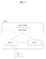
- FIG. 1 is a diagram showing a network structure of an Evolved Universal Mobile Telecommunications System (E-UMTS) as a radio communication system.
- E-UMTS is an evolved form of the UMTS and has been standardized in the 3GPP.
- the E-UMTS may be called a Long Term Evolution (LTE) system.
- LTE Long Term Evolution
- the E-UMTS mainly includes a User Equipment (UE) 120, base stations (or eNBs or eNode Bs) 110a and 110b, and an Access Gateway (AG) which is located at an end of a network (E-UTRAN) and which is connected to an external network.
- UE User Equipment
- base stations or eNBs or eNode Bs
- AG Access Gateway
- an eNB can simultaneously transmit multiple data streams for a broadcast service, a multicast service and/or a unicast service.
- One or more cells may exist per eNB.
- the cell is set to use a bandwidth such as 1.25, 2.5, 5, 10, 15 or 20 MHz to provide a downlink or uplink transmission service to several UEs. Different cells may be set to provide different bandwidths.
- the eNB controls data transmission or reception of a plurality of UEs.
- the eNB transmits downlink (DL) scheduling information of DL data so as to inform a corresponding UE of time/frequency domain in which data is transmitted, coding, data size, and Hybrid Automatic Repeat and reQest (HARQ)-related information.
- DL downlink
- HARQ Hybrid Automatic Repeat and reQest
- the eNB transmits uplink (UL) scheduling information of UL data to a corresponding UE so as to inform the UE of a time/frequency domain which may be used by the UE, coding, data size and HARQ-related information.
- UL uplink
- An interface for transmitting user traffic or control traffic can be used between eNBs.
- a Core Network (CN) may include the AG and a network node or the like for user registration of the UE.
- the AG manages mobility of a UE on a Tracking Area (TA) basis.
- One TA includes a plurality of cells.
- LTE Long Term Evolution
- WCDMA Wideband Code Division Multiple Access
- UE User Equipment
- LTE-Advanced LTE-Advanced
- the LTE system and the LTE-A system are different from each other in terms of system bandwidth.
- the LTE-A system aims to support a wideband of a maximum of 100 MHz.
- the LTE-A system uses carrier aggregation or bandwidth aggregation technology which achieves the wideband using a plurality of frequency blocks.
- the carrier aggregation enables the plurality of frequency blocks to be used as one large logical frequency band in order to use a wider frequency band.
- the bandwidth of each of the frequency blocks may be defined based on the bandwidth of a system block used in the LTE system.
- Each frequency block is transmitted using a component carrier.
- An object of the present invention is to provide a method for transmitting a downlink signal in a radio communication system and an apparatus therefor.
- the object of the present invention can be achieved by providing a method for transmitting a downlink signal by a base station in a radio communication system, including allocating transmission resources to data symbols for transmitting the downlink signal in a direction in which a frequency index is increased, and transmitting the downlink signal to a user equipment using the allocated resources, wherein a frequency band of preset orthogonal frequency division multiplexing symbols of the transmission resources includes a control region and a segment band, and wherein the allocating the transmission resources includes puncturing the data symbols, to which the control region included in the preset OFDM symbols is allocated, using a control channel.
- the allocating the transmission resources may include allocating time resources to the data symbols in a direction in which an OFDM symbol index is increased.
- a base station apparatus of a radio communication system including a processor configured to allocate transmission resources to data symbols for transmitting a downlink signal in a direction in which a frequency index is increased, and a transmission module configured to transmit the downlink signal to a user equipment using the allocated resources, wherein a frequency band of preset orthogonal frequency division multiplexing (OFDM) symbols of the transmission resources includes a control region and a segment band, and wherein the data symbols, to which the control region included in the preset OFDM symbols is allocated, are punctured using a control channel.
- the processor may allocate time resources to the data symbols in a direction in which an OFDM symbol index is increased.
- the control region included in a first OFDM symbol of the preset OFDM symbols may not be allocated to the data symbols or the control region included in the preset OFDM symbols may not be allocated to the data symbols.
- Component carriers over which the segment band is transmitted may be different from component carriers over which a legacy band corresponding to the control region is transmitted.
- FIG. 1 is a diagram showing a network structure of an Evolved Universal Mobile Telecommunications System (E-UMTS) as an example of a wireless communication system.
- E-UMTS Evolved Universal Mobile Telecommunications System
- FIG. 2 is a diagram showing a radio interface protocol architecture between a User Equipment (UE) and an Evolved Universal Terrestrial Radio Access Network (E-UTRAN) based on a 3 rd Generation Partnership Project (3GPP) radio access network standard.
- UE User Equipment
- E-UTRAN Evolved Universal Terrestrial Radio Access Network
- 3GPP 3 rd Generation Partnership Project
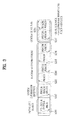
- FIG. 3 is a diagram showing physical channels used in a 3GPP system and a general signal transmission method using the same.
- FIG. 4 is a diagram showing the structure of a radio frame used in a Long Term Evolution (LTE) system.
- LTE Long Term Evolution
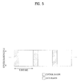
- FIG. 5 is a diagram showing the functional structure of a downlink radio frame in an LTE system.
- FIG. 6 is a diagram showing a resource grid for a downlink slot in an LTE system.
- FIG. 7 is a diagram showing a control channel included in a control region of a subframe in an LTE system.
- FIG. 8 is a flowchart illustrating a method of separating an information part and a parity part of a coded code block and performing rate matching.
- FIG. 9 is a conceptual diagram illustrating carrier aggregation.
- FIG. 10 is a diagram illustrating a segment band defined in an LTE-A system.
- FIG. 11 is a diagram illustrating a method of allocating resources for transmitting a downlink signal according to a first embodiment of the present invention.
- FIG. 12 is a diagram illustrating a method of mapping data symbols for transmitting a downlink signal according to a second embodiment of the present invention.
- FIG. 13 is a diagram showing an example of mapping data symbols of a downlink signal transmitted to a specific UE according to the second embodiment of the present invention.
- FIG. 14 is a diagram illustrating a method of mapping data symbols for transmitting a downlink signal according to the second embodiment of the present invention.
- FIG. 15 is a diagram illustrating a method of mapping data symbols for transmitting a downlink signal according to a third embodiment of the present invention.
- FIG. 16 is a diagram illustrating a method of mapping data symbols for transmitting a downlink signal according to a fourth embodiment of the present invention.
- FIG. 17 is a diagram illustrating a method of mapping data symbols for transmitting a downlink signal according to a fifth embodiment of the present invention.
- FIG. 18 is a diagram illustrating a method of mapping data symbols for transmitting a downlink signal according to a sixth embodiment of the present invention.
- FIG. 19 is a block diagram showing a transmitter and receiver according to an embodiment of the present invention.
- a 3GPP LTE (Release-8) system is called an LTE system or a legacy system.
- a user equipment (UE) which supports an LTE system is called an LTE UE or a legacy UE.
- a 3GPP LTE-A (Release-9) system is called an LTE-A system or an evolved system.
- a UE which supports an LTE-A system is called an LTE-A UE or an evolved UE.
- the embodiments of the present invention are described using the LTE system and the LTE-A system in the present specification, the embodiments of the present invention are applicable to any communication system corresponding to the above definition.
- the embodiments of the present invention are described based on a Frequency Division Duplex (FDD) scheme in the present specification, the embodiments of the present invention may be easily modified and applied to a Half-Duplex FDD (H-FDD) scheme or a Time Division Duplex (TDD) scheme.
- FDD Frequency Division Duplex
- H-FDD Half-Duplex FDD
- TDD Time Division Duplex
- FIG. 2 shows a control plane and a user plane of a radio interface protocol between a UE and an Evolved Universal Terrestrial Radio Access Network (E-UTRAN) based on a 3GPP radio access network standard.
- the control plane refers to a path used for transmitting control messages used for managing a call between the UE and the network.
- the user plane refers to a path used for transmitting data generated in an application layer, e.g., voice data or Internet packet data.
- a physical (PHY) layer of a first layer provides an information transfer service to a higher layer using a physical channel.
- the PHY layer is connected to a Medium Access Control (MAC) layer located on a higher layer via a transport channel. Data is transported between the MAC layer and the PHY layer via the transport channel. Data is also transported between a physical layer of a transmitting side and a physical layer of a receiving side via a physical channel.
- the physical channel uses a time and a frequency as radio resources. More specifically, the physical channel is modulated using an Orthogonal Frequency Division Multiple Access (OFDMA) scheme in downlink and is modulated using a Single-Carrier Frequency Division Multiple Access (SC-FDMA) scheme in uplink.
- OFDMA Orthogonal Frequency Division Multiple Access
- SC-FDMA Single-Carrier Frequency Division Multiple Access
- a Medium Access Control (MAC) layer of a second layer provides a service to a Radio Link Control (RLC) layer of a higher layer via a logical channel.
- the RLC layer of the second layer supports reliable data transmission.
- the function of the RLC layer may be implemented by a functional block within the MAC.
- a Packet Data Convergence Protocol (PDCP) layer of the second layer performs a header compression function to reduce unnecessary control information for efficient transmission of an Internet Protocol (IP) packet such as an IPv4 packet or an IPv6 packet in a radio interface having a relatively small bandwidth.
- IP Internet Protocol
- a Radio Resource Control (RRC) layer located at the bottom of a third layer is defined only in the control plane and is responsible for control of logical, transport, and physical channels in association with configuration, reconfiguration, and release of Radio Bearers (RBs).
- the RB is a service that the second layer provides for data communication between the UE and the network.
- the RRC layer of the UE and the RRC layer of the network exchange RRC messages.
- the UE is in an RRC connected mode if an RRC connection has been established between the RRC layer of the radio network and the RRC layer of the UE. Otherwise, the UE is in an RRC idle mode.
- a Non-Access Stratum (NAS) layer located above the RRC layer performs functions such as session management and mobility management.
- NAS Non-Access Stratum
- One cell of the eNB is set to use a bandwidth such as 1.25, 2.5, 5, 10, 15 or 20 MHz to provide a downlink or uplink transmission service to UEs. Different cells may be set to provide different bandwidths.
- Downlink transport channels for transmission of data from the network to the UE include a Broadcast Channel (BCH) for transmission of system information, a Paging Channel (PCH) for transmission of paging messages, and a downlink Shared Channel (SCH) for transmission of user traffic or control messages.
- BCH Broadcast Channel
- PCH Paging Channel
- SCH downlink Shared Channel
- User traffic or control messages of a downlink multicast or broadcast service may be transmitted through a downlink SCH and may also be transmitted through a downlink multicast channel (MCH).
- Uplink transport channels for transmission of data from the UE to the network include a Random Access Channel (RACH) for transmission of initial control messages and an uplink SCH for transmission of user traffic or control messages.
- RACH Random Access Channel
- Logical channels which are located above the transport channels and are mapped to the transport channels, include a Broadcast Control Channel (BCCH), a Paging Control Channel (PCCH), a Common Control Channel (CCCH), a Multicast Control Channel (MCCH), and a Multicast Traffic Channel (MTCH).
- BCCH Broadcast Control Channel
- PCCH Paging Control Channel
- CCCH Common Control Channel
- MCCH Multicast Control Channel
- MTCH Multicast Traffic Channel
- FIG. 3 is a diagram showing physical channels used in a 3GPP system and a general signal transmission method using the same.
- a UE performs an initial cell search operation such as synchronization with an eNB when power is turned on or the UE enters a new cell (S301).
- the UE may receive a Primary Synchronization Channel (P-SCH) and a Secondary Synchronization Channel (S-SCH) from the eNB, perform synchronization with the eNB, and acquire information such as a cell ID. Thereafter, the UE may receive a physical broadcast channel from the eNB so as to acquire broadcast information within the cell. Meanwhile, the UE may receive a Downlink Reference Signal (DL RS) so as to confirm a downlink channel state in the initial cell search step.
- P-SCH Primary Synchronization Channel
- S-SCH Secondary Synchronization Channel
- DL RS Downlink Reference Signal
- the UE which completes the initial cell search may receive a Physical Downlink Control Channel (PDCCH) and a Physical Downlink Shared Channel (PDSCH) according to information included in the PDCCH so as to acquire more detailed system information (S302).
- PDCH Physical Downlink Control Channel
- PDSCH Physical Downlink Shared Channel
- the UE may perform a Random Access Procedure (RACH) (step S303 to S306) with respect to the eNB.
- RACH Random Access Procedure
- the UE may transmit a specific sequence through a Physical Random Access Channel (PRACH) as a preamble (S303 and S305), and receive a response message of the preamble through the PDCCH and the PDSCH corresponding thereto (S304 and S306).
- PRACH Physical Random Access Channel
- S304 and S306 receive a response message of the preamble through the PDCCH and the PDSCH corresponding thereto.
- a contention resolution procedure may be further performed.
- the UE which performs the above procedures may perform PDCCH/PDSCH reception (S307) and Physical Uplink Shared Channel PUSCH)/Physical Uplink Control Channel (PUCCH) transmission (S308) as a general uplink/downlink signal transmission procedure.
- the control information transmitted from the UE to the eNB in uplink or transmitted from the eNB to the UE in downlink includes a downlink/uplink ACK/NACK signal, a Channel Quality Indicator (CQI), a Precoding Matrix Index (PMI), a Rank Indicator (RI), and the like.
- the UE may transmit the control information such as CQI/PMI/RI through the PUSCH and/or the PUCCH.
- FIG. 4 is a diagram showing the structure of a radio frame used in a Long Term Evolution (LTE) system.
- LTE Long Term Evolution
- the radio frame has a length of 10 ms (327200 ⁇ T s ) and includes 10 subframes with the same size.
- Each of the subframes has a length of 1 ms and includes two slots.
- Each of the slots has a length of 0.5 ms (15360 ⁇ T s ).
- Each slot includes a plurality of OFDM or SC-FDMA symbols in a time domain, and includes a plurality of resource blocks (RBs) in a frequency domain. In the LTE system, one RB includes 12 subcarriers ⁇ 7(6) OFDM or SC-FDMA symbols.
- a Transmission Time Interval (TTI) which is a unit time for transmission of data may be determined in units of one or more subframes.
- the structure of the radio frame is only exemplary and the number of subframes included in the radio frame, the number of slots included in the subframe, or the number of OFDM or SC-FDMA symbols included in the slot may be variously changed.
- FIG. 5 is a diagram showing the structure of a downlink radio frame in an LTE system.
- the downlink radio frame includes 10 subframes with the same length.
- the subframe is defined as the basic time unit of packet scheduling with respect to an overall downlink frequency.
- Each subframe is divided into a control region for transmission of scheduling information and other control channels and a data region for transmission of downlink data.
- the control region starts from a first OFDM symbol of a subframe and includes one or more OFDM symbols.
- the size of the control region may be independently set for each subframe.
- the control region is used to transmit an L1/L2 (layer 1/layer 2) control signal.
- the data region is used to transmit downlink traffic.
- FIG. 6 is a diagram showing a resource grid for a downlink slot in an LTE system.
- the downlink slot includes N symb DL OFDM symbols in a time domain and N RB DL RBs in a frequency domain. Since each RB includes N sc RB subcarriers, the downlink slot includes N RB DL ⁇ N sc RB subcarriers in the frequency domain. Although the downlink slot includes 7 OFDM symbols and the RB includes 12 subcarriers in, the present invention is not limited thereto. For example, the number of OFDM symbols included in the downlink slot may be changed according to the length of cyclic prefix (CP).
- CP cyclic prefix
- Each element on the resource grid is referred to as a resource element (RE) and one RE is indicated by one OFDM symbol index and one subcarrier index.
- One RB includes N symb DL ⁇ N sc RB REs.
- the number N RB DL of RBs included in the downlink slot depends on a downlink transmission bandwidth set in the cell.
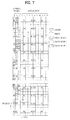
- FIG. 7 is a diagram showing a control channel included in a control region of a subframe in an LTE system.
- the subframe is composed of 14 OFDM symbols. According to the configuration of the subframe, the first one to three OFDM symbols are used as the control region and the remaining 13 to 11 OFDM symbols are used as the data region.
- R1 to R4 denote Reference Signals (RS) of antennas 0 to 3.
- the RS is fixed within the subframe with a constant pattern regardless of the control region and the data region.
- Control channels are resources, to which the RSs are not allocated, in the control region, and traffic channels are allocated to resources, to which the RSs are not allocated, in the data region.
- the control channels allocated to the control region include a Physical Control Format Indicator Channel (PCFICH), a Physical Hybrid-ARQ Indicator Channel (PHICH), a Physical Downlink Control Channel (PDCCH), and the like.
- PCFICH Physical Control Format Indicator Channel
- PHICH Physical Hybrid-ARQ Indicator Channel
- PDCCH Physical Downlink Control Channel
- the PCFICH informs the UE of the number of OFDM symbols used in the PDCCH for each subframe.
- the PCFICH is located at a first OFDM symbol and is set prior to the PHICH and the PDCCH.
- the PCFICH is composed of four Resource Element Groups (REGs), and the REGs are distributed within the control region based on a cell Identity (ID).
- REG Resource Element Group
- One REG is composed of four Resource Elements (REs).
- the structure of the REG will be described in detail with reference to FIG. 8 .
- the PCFICH value indicates values of 1 to 3 and is modulated using a Quadrature Phase Shift Keying (QPSK) scheme.
- QPSK Quadrature Phase Shift Keying
- the PHICH is used to transfer HARQ ACK/NACK in uplink transmission.
- the PHICH is composed of three REGs and is scrambled on cell-specific basis.
- the ACK/NACK signal is indicated by 1 bit, is spread using a Spreading Factor (SF) of 2 or 4, and is repeated three times.
- SF Spreading Factor
- a plurality of PHICHs may be mapped to the same resources.
- the PHICH is modulated using a binary phase shift keying (BPSK) scheme.
- BPSK binary phase shift keying
- the PDCCH is allocated to first n OFDM symbols of the subframe.
- n is an integer of 1 or more and is indicated by the PCFICH.
- the PDCCH is composed of one or more Control Channel Elements (CCEs), which will be described in detail below.
- CCEs Control Channel Elements
- the PDCCH informs UEs or a UE group of information associated with resource allocation of a Paging Channel (PCH) and a Downlink-Shared Channel (DL-SCH) of a transport channel, Uplink scheduling Grant, HARQ information or the like.
- PCH Paging Channel
- DL-SCH Downlink-Shared Channel
- the PCH and the DL-SCH are transmitted through the PDSCH. Accordingly, the eNB and the UE generally transmit and receive data through the PDSCH except for specific control information or specific service data.
- Radio Network Temporary Identity e.g., Radio Network Temporary Identity
- information about data transmitted using radio resource e.g., frequency location
- transmission format information e.g., transmission block size, modulation scheme, coding information, or the like
- one or more UEs located within a cell monitor the PDCCH using RNTI information thereof, and if one or more UEs having "A" RNTI are present, the UEs receive the PDCCH and receive the PDSCH indicated by "B" and "C" through the information about the received PDCCH.
- a transmitter performs channel coding.
- a receiver performs coding with respect to information transmitted from the transmitter using a forward error correction code and transmits the coded information, in order to correct a signal error which occurs in a channel.
- the receiver demodulates the received signal and performs a decoding process on the forward error correction code so as to restore the transmitted information.
- the receiver corrects the error of the received signal, which occurs in the channel, in the decoding process.
- the turbo encoder includes a Recursive Systematic Convolution (RSC) encoder and an interleaver.
- RSC Recursive Systematic Convolution
- the turbo encoder includes a Recursive Systematic Convolution (RSC) encoder and an interleaver. It is known that, as the size of an input data block is increased, the performance of the turbo encoder is improved.
- a data block having a predetermined size or more is segmented into several small data blocks and coding is performed.
- the segmented small data block is called a code block.
- Code blocks generally have the same size, but one code block may have a size different from that of the other code blocks due to a limit in size of the interleaver.
- a CRC may be added to each of the code blocks for error detection.
- the RSC encoder performs a forward error correction coding process according to the predetermined size of the interleaver, that is, in the code block units. Then, the interleaver performs interleaving in order to reduce influence of a burst error occurring upon transmission of the signal through a radio channel. Then, the signal is transmitted in a state of being mapped to the radio resources.
- the encoded code block should be subjected to rate matching.
- rate matching includes puncturing or repetition. Rate matching may be performed in the encoded code block units.
- the encoded code block may be segmented into an information (systematic data) part and a parity bit part and the segmented parts may be separately subjected to rate matching.
- FIG. 8 is a flowchart illustrating a method of segmenting an information part and a parity part of an encoded code block so as to perform rate matching. In FIG. 8 , it is assumed that a code rate is 1/3.
- FIG. 9 is a conceptual diagram illustrating carrier aggregation.
- Carrier aggregation refers to a method of using a plurality of component carriers as a large logical frequency band in order to use a wider frequency band in a radio communication system.
- an entire system band has a maximum bandwidth of 100 MHz.
- the entire system band includes five component carriers (CCs) and each CC has a maximum bandwidth of 20 MHz.
- the CC includes one or more physically contiguous subcarriers. Although all CCs have the same bandwidth in FIG. 9 , this is only exemplary and the CCs may have different bandwidths. Although the CCs are shown as being contiguous in the frequency domain, the CCs may be physically contiguous or separated.
- Different center frequencies may be used for the CCs or one common center frequency may be used for physically contiguous CCs.
- a center frequency A may be used.
- a center frequency B and the like may be used for the respective CCs.
- the CC may correspond to a system band of a legacy system.
- the CC may be characterized by the legacy system, it is possible to facilitate backward compatibility and system design in a radio communication environment in which an evolved UE and a legacy UE coexist.
- the LTE-A system supports carrier aggregation
- each CC may correspond to the system band of the LTE system.
- the CC may have any one bandwidth such as 1.25, 2.5, 5, 10 or 20 MHz.
- a frequency band used for communication with each UE is defined in CC units.
- a UE A may use 100 MHz which is the bandwidth of the entire system band and perform communication using all five component carriers.
- Each of UEs B 1 to B 5 may only use a bandwidth of 20 MHz and perform communication using one CC.
- Each of UEs C 1 and C 2 may use a bandwidth of 40 MHz and perform communication using two CCs.
- the two CCs may be contiguous or discontiguous.
- the UE C 1 uses two discontiguous CCs and the UE C 2 uses two contiguous CCs.
- FIG. 10 is a diagram illustrating a scheduling method in an LTE-A system.
- One downlink CC and one uplink CC may be used in the LTE system and several CCs may be used in the LTE-A system as shown in FIG. 10 .
- a method of scheduling a data channel by a control channel may be divided into a linked carrier scheduling method and a cross carrier scheduling method.
- a control channel transmitted via a specific CC schedules only a data channel via the specific CC.
- a control channel transmitted via a primary CC using a carrier indicator (CI) schedules a data channel transmitted via the primary CC or another CC.
- CI carrier indicator
- the cross carrier scheduling method causes serious errors as compared to the linked carrier scheduling method when errors occur in the CI. For example, if errors occur in the CI transmitted via the primary CC, the location of an OFDM symbol in which a data region is started is changed in different CCs. Thus, in a receiver, code bits located at different locations may be combined in a HARQ buffer combining process.
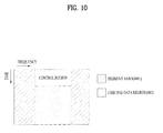
- FIG. 10 is a diagram illustrating a segment band defined in an LTE-A system.
- the segment band is a region added to a downlink subframe of the existing LTE system and refers to a frequency band in which a control region for transmitting physical control channels such as a PDCCH, a PHICH and a PFFICH is not included.
- the region excluding the existing LTE subframe may be defined as the segment band. If the frequency band of one downlink CC has an unnormalized bandwidth of 14 MHz, 10 MHz of a downlink frequency band of the existing LTE system is located in the middle of the frequency band and the remaining frequency band of 4 MHz is located at both sides of the downlink subframe of the LTE system by 2 MHz as the segment bands.
- a PDSCH which is a data channel may be mapped.
- the present invention proposes a method of mapping a PDSCH in a downlink CC including a segment band.
- OFDM symbols included in one subframe are divided into symbols which transmit a control signal and symbols which do not transmit a control signal, which will be described in detail with reference to the drawings.
- FIG. 11 is a diagram illustrating a method of mapping data symbols for transmitting a downlink signal according to a first embodiment of the present invention.
- data channel mapping in the newly defined RB may also be independently defined. That is, the newly defined RB is subdivided into a plurality of RBs or one RB may be configured.
- a data symbol mapping method based on all frequency resources and time resources included in one subframe is described in the following embodiments, from the viewpoint of a specific UE, a data symbol mapping method according to each embodiment is applied within RBs allocated to the UE.
- FIG. 12 is a diagram illustrating a method of mapping data symbols for transmitting a downlink signal according to a second embodiment of the present invention.
- data symbols are mapped starting from a start OFDM symbol in the direction in which an OFDM symbol index is increased.
- Data symbols are mapped only to segment band excluding the control region in the OFDM symbols including the control region and data symbols are mapped to the segment band and the legacy band in the direction in which the frequency resource index is increased in the OFDM symbols including only the data region.
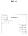
- FIG. 13 is a diagram showing an example of mapping data symbols of a downlink signal transmitted to a specific UE according to the second embodiment of the present invention.
- shadow regions denote RBs allocated to the specific UE and the data symbols are mapped in the direction in which the frequency index is increased. That is, from the viewpoint of the specific UE, as shown in FIG. 13 , the data symbol mapping method for transmitting the downlink signal, which is proposed by the present invention, is applicable within the RBs allocated to the UE.
- FIG. 14 is a diagram illustrating a method of mapping data symbols for transmitting a downlink signal according to the second embodiment of the present invention.
- the data symbols are not mapped to the control region in the OFDM symbols including the control region in FIG. 13
- the data symbols are also mapped to the control region in FIG. 14(a) .
- the data symbols mapped to the control region are not actually transmitted and are punctured by the control channel. That is, while the eNB maps the control channel to the control region and transmits the control channel, the UE sequentially reads data on the assumption that the data symbols are mapped to the control region.
- the signal transmitted via the control region may be recognized as noise upon data decoding. Accordingly, in a data decoding buffer of the UE, errors do not occur due to the signal transmitted via the control region.
- data symbols are mapped to all OFDM symbols excluding a minimum control region for preventing PCFICH errors, for example, a control region of a first OFDM symbol.
- the data symbols mapped to the OFDM symbols including the control region excluding the first OFDM symbol are punctured by the control channel. Since the minimum control region is always occupied by the control channel, the method shown in FIG. 14(b) is more efficient than the method shown in FIG. 14(a) in that the amount of data symbols punctured by the control channel is reduced.
- FIG. 15 is a diagram illustrating a method of mapping data symbols for transmitting a downlink signal according to a third embodiment of the present invention.
- the data symbols are preferentially mapped starting from an OFDM symbol which does not include the control region in the direction in which the symbol index is increased. Thereafter, the data symbols are mapped to the segment band of the remaining OFDM symbols.
- a conventional data reading method of a UE may be applied to the OFDM symbols which do not include at least the segment band.
- the data symbols are preferentially mapped to the frequency band of the OFDM symbol next to the OFDM symbol including a minimum control region for preventing PCFICH errors, for example, the first OFDM symbol. Then, the data symbols are mapped to the remaining OFDM symbol, that is, the first OFDM symbol, excluding the minimum control region. Finally, the data symbols mapped to the actual control region are punctured by the control channel and are not transmitted.
- FIG. 16 is a diagram illustrating a method of mapping data symbols for transmitting a downlink signal according to a fourth embodiment of the present invention.
- the data symbols are preferentially mapped to the frequency band of the last OFDM symbol of one subframe, unlike the above-described embodiments.
- the UE since the UE performs reading from the data region, not from the control region, even when errors occur when the UE recognizes the actual control region, it is possible guarantee data reception robustness.
- the data symbols are preferentially mapped to the frequency band of the last OFDM symbol and are then mapped to the OFDM symbol including the control region. Similarly, the data symbols mapped to the control region are punctured by the control channel and are not transmitted.
- the data symbols are preferentially mapped to the frequency band of the last OFDM symbol and are then mapped to the OFDM symbol including the control region.
- the data symbols are not mapped to the minimum control region.
- the data maps mapped to the actual control region are punctured by the control channel and are not transmitted.
- the data symbols are preferentially mapped to the frequency band of the last OFDM symbol. However, in the OFDM symbols including the control region, the data symbols are not mapped to the control region of the OFDM symbols.
- the segment band and the existing frequency band that is, the legacy band
- a method of preferentially mapping the data symbols to the segment band and then mapping the data symbols to the legacy band will be described.
- FIG. 17 is a diagram illustrating a method of mapping data symbols for transmitting a downlink signal according to a fifth embodiment of the present invention.
- the data symbols are mapped in the direction in which the symbol index is increased.
- the data symbols are mapped to the segment band starting from the first OFDM symbol in the direction in which the symbol index is increased, but are not mapped to the control region. Then, the data symbols are mapped to the data region of the legacy band in the direction in which the symbol index is increased.
- the data symbols are preferentially mapped to the segment band starting from the first OFDM symbol and are then mapped to the legacy band. At this time, the data symbols are also mapped to the OFDM symbols including the control region. The data symbols mapped to the actual control region are punctured and are not transmitted.
- the data symbols are preferentially mapped to the segment band starting from the first OFDM symbol and are then mapped to the legacy band. At this time, the data symbols are mapped to the OFDM symbols including the control region excluding the minimum control region for preventing PCFICH errors in the first OFDM symbol. Finally, the data symbols mapped to the actual control region are punctured and are not transmitted.
- the data symbols are mapped in the direction in which the symbol index is decreased.
- the data symbols are also mapped to the OFDM symbols including the control region similarly to FIG. 17(b) .
- the data symbols mapped to the actual control region are punctured and are not transmitted.
- the data symbols are mapped to the OFDM symbols including the control region excluding the minimum control region of the first OFDM symbol and the data symbols mapped to the actual control region are punctured and are not transmitted.
- the data symbols are preferably mapped to the legacy band in order to map systematic bits of the coded code block to the existing frequency band.
- a method of preferentially mapping the data symbols to the legacy band and then mapping the data symbols to the segment band will be described.
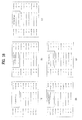
- FIG. 18 is a diagram illustrating a method of mapping data symbols for transmitting a downlink signal according to a sixth embodiment of the present invention.
- the data symbols are mapped in the direction in which the symbol index is increased.
- the data symbols are preferentially mapped to the data region of the legacy band in the direction in which the symbol index is increased and the data symbols are then mapped to the segment band in the direction in which the symbol index is increased.
- the data symbols are preferentially mapped to the OFDM symbols including the control region of the legacy band and the data symbols are then mapped to the segment band.
- the data symbols mapped to the actual control region are punctured and are not transmitted.
- the data symbols are preferentially mapped to the OFDM symbols including the control region of the legacy band excluding the minimum control region for preventing PCFICH errors of the first OFDM symbol. Then, the data symbols are mapped to the segment band. The data symbols mapped to the actual control region are punctured and are not transmitted.
- the data symbols are preferentially mapped to the last OFDM symbol in the direction in which the symbol index is decreased.
- the data symbols are also mapped to the OFDM symbols including the control region similarly to FIG. 18(d) .
- the data symbols mapped to the actual control region are punctured and are not transmitted.
- the data symbols are mapped to the OFDM symbols including the control region excluding the minimum control region of the first OFDM symbol similarly to FIG. 18(c) .
- the data symbols mapped to the actual control region are punctured and are not transmitted.
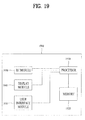
- FIG. 19 is a block diagram showing a transmitter and receiver according to an embodiment of the present invention.
- a transmitter/receiver 1900 includes a processor 1910, a memory 1920, a Radio Frequency (RF) module 1930, a display module 1940 and a user interface module 1950.
- RF Radio Frequency
- the transmitter/receiver 1900 is shown for convenience of description and some modules thereof may be omitted. In addition, the transmitter/receiver 1900 may further include necessary modules. In addition, some modules of the transmitter/receiver 1900 may be subdivided.
- the processor 1910 is configured to perform an operation of the embodiment of the present invention described with respect to the drawings.
- the processor 1910 may perform a function for generating a control signal and mapping the control signal to a control channel set within a plurality of frequency blocks. If the transmitter/receiver 1900 is a portion of a UE, the processor 1910 may confirm a control channel indicated thereto from a signal received through a plurality of frequency blocks and extract a control signal.
- the processor 1910 may perform a necessary operation based on the control signal.
- the processor 1910 may perform a necessary operation based on the control signal.
- FIGs. 1 to 18 For a detailed description of the operation of the processor 1910, reference may be made to the description associated with FIGs. 1 to 18 .
- the memory 1920 is connected to the processor 1910 so as to store an operating system, an application, program code, data and the like.
- the RF module 1930 is connected to the processor 1910 so as to perform a function for converting a baseband signal into a radio signal or converting a radio signal into a baseband signal.
- the RF module 1930 performs analog conversion, amplification, filtering and frequency up-conversion or inverse processes thereof.
- the display module 1940 is connected to the processor 1910 so as to display a variety of information.
- a known device such as a Liquid Crystal Display (LCD), a Light Emitting Diode (LED), or an Organic Light Emitting Diode (OLED) may be used.
- the user interface module 1950 is connected to the processor 1910 and may be configured by a combination of known user interfaces such as a keypad and a touch screen.
- the above-mentioned embodiments of the present invention are disclosed on the basis of a data communication relationship between a base station and a user equipment. Specific operations to be conducted by the base station in the present invention may also be conducted by an upper node of the base station as necessary. In other words, it will be obvious to those skilled in the art that various operations for enabling the base station to communicate with the user equipment in a network composed of several network nodes including the base station will be conducted by the base station or other network nodes other than the base station.
- the term "Base Station” may be replaced with the terms fixed station, Node-B, eNode-B (eNB), or access point as necessary.
- UE User Equipment
- SS subscriber station
- MSS mobile subscriber station
- the embodiments of the present invention can be implemented by a variety of means, for example, hardware, firmware, software, or a combination thereof.
- the present invention can be implemented through application specific integrated circuits (ASICs), Digital signal processors (DSPs), digital signal processing devices (DSPDs), programmable logic devices (PLDs), field programmable gate arrays (FPGAs), a processor, a controller, a microcontroller, a microprocessor, etc.
- ASICs application specific integrated circuits
- DSPs Digital signal processors
- DSPDs digital signal processing devices
- PLDs programmable logic devices
- FPGAs field programmable gate arrays
- processor a controller, a microcontroller, a microprocessor, etc.
- the present invention can be implemented in the form of a variety of formats, for example, modules, procedures, functions, etc.
- the software codes may be stored in a memory unit so as to be driven by a processor.
- the memory unit may be located inside or outside of the processor, so that it can communicate with the aforementioned processor via a variety of well-known parts.
- the present invention is applicable to a radio communication system and, more particularly, to a method and apparatus for transmitting an aperiodic sounding reference signal in a radio communication system to which carrier aggregation is applied.
Landscapes
- Engineering & Computer Science (AREA)
- Signal Processing (AREA)
- Computer Networks & Wireless Communication (AREA)
- Mobile Radio Communication Systems (AREA)
Applications Claiming Priority (2)
| Application Number | Priority Date | Filing Date | Title |
|---|---|---|---|
| US28635109P | 2009-12-14 | 2009-12-14 | |
| PCT/KR2010/008845 WO2011074836A2 (ko) | 2009-12-14 | 2010-12-10 | 무선 통신 시스템에서 하향링크 신호 송신 방법 및 이를 위한 장치 |
Publications (2)
| Publication Number | Publication Date |
|---|---|
| EP2421314A2 true EP2421314A2 (de) | 2012-02-22 |
| EP2421314A4 EP2421314A4 (de) | 2016-04-20 |
Family
ID=44167840
Family Applications (1)
| Application Number | Title | Priority Date | Filing Date |
|---|---|---|---|
| EP10837832.4A Ceased EP2421314A4 (de) | 2009-12-14 | 2010-12-10 | Verfahren zur übertragung eines downlink-signals in einem drahtlosen kommunikationssystem und vorrichtung dafür |
Country Status (4)
| Country | Link |
|---|---|
| US (1) | US8582523B2 (de) |
| EP (1) | EP2421314A4 (de) |
| KR (1) | KR101804918B1 (de) |
| WO (1) | WO2011074836A2 (de) |
Families Citing this family (7)
| Publication number | Priority date | Publication date | Assignee | Title |
|---|---|---|---|---|
| WO2011080842A1 (ja) * | 2009-12-29 | 2011-07-07 | 富士通株式会社 | 基地局および制御チャネルのマッピング方法 |
| WO2012155326A1 (en) * | 2011-05-16 | 2012-11-22 | Renesas Mobile Corporation | Method and apparatus for configuring sounding reference signal for segment carrier |
| CN105357773B (zh) * | 2011-07-15 | 2020-06-02 | 华为技术有限公司 | 一种无线宽带通信方法,装置和系统 |
| WO2013040070A1 (en) * | 2011-09-12 | 2013-03-21 | Ntt Docomo, Inc. | Method and apparatus at the physical and link layer for mobile communications |
| CN103580772B (zh) * | 2012-07-18 | 2017-06-06 | 华为技术有限公司 | 数据传输方法、系统及设备,终端获取数据的方法及终端 |
| US10616914B2 (en) * | 2017-01-06 | 2020-04-07 | Qualcomm Incorporated | Unicast data transmission on a downlink common burst of a slot using mini-slots |
| KR102629072B1 (ko) * | 2018-11-13 | 2024-01-24 | 한국전자통신연구원 | 무선 통신 시스템에서의 데이터 재전송 방법 및 장치 |
Family Cites Families (7)
| Publication number | Priority date | Publication date | Assignee | Title |
|---|---|---|---|---|
| KR100885476B1 (ko) * | 2006-05-02 | 2009-02-24 | 한국전자통신연구원 | 직교 주파수 분할 다중 접속 시스템에서의 하향링크스케줄링 정보 송/수신 방법 |
| US8254245B2 (en) | 2007-04-27 | 2012-08-28 | Lg Electronics Inc. | Method for transmitting downlink control channel in a mobile communications system and a method for mapping the control channel to physical resource using block interleaver in a mobile communications system |
| KR20080096356A (ko) | 2007-04-27 | 2008-10-30 | 엘지전자 주식회사 | 다수 셀 환경의 무선 통신 시스템에서 하향링크 제어채널을전송하는 방법 |
| WO2009045734A2 (en) * | 2007-10-01 | 2009-04-09 | Lucent Technologies, Inc. | Multiplexing pucch information |
| KR101058720B1 (ko) | 2007-10-12 | 2011-08-22 | 삼성전자주식회사 | 통신 시스템에서 자원 할당 정보 송수신 장치 및 방법 |
| KR101505686B1 (ko) | 2008-03-23 | 2015-03-25 | 엘지전자 주식회사 | 가변 서브프레임을 이용한 무선자원 할당 방법 |
| WO2011008023A2 (en) * | 2009-07-15 | 2011-01-20 | Lg Electronics Inc. | Method and apparatus for controlling uplink power in a wireless communication system |
-
2010
- 2010-12-10 WO PCT/KR2010/008845 patent/WO2011074836A2/ko not_active Ceased
- 2010-12-10 KR KR1020117026689A patent/KR101804918B1/ko not_active Expired - Fee Related
- 2010-12-10 EP EP10837832.4A patent/EP2421314A4/de not_active Ceased
- 2010-12-10 US US13/319,664 patent/US8582523B2/en not_active Expired - Fee Related
Non-Patent Citations (1)
| Title |
|---|
| See references of WO2011074836A2 * |
Also Published As
| Publication number | Publication date |
|---|---|
| KR20120111927A (ko) | 2012-10-11 |
| KR101804918B1 (ko) | 2018-01-11 |
| EP2421314A4 (de) | 2016-04-20 |
| WO2011074836A2 (ko) | 2011-06-23 |
| WO2011074836A3 (ko) | 2011-11-03 |
| US8582523B2 (en) | 2013-11-12 |
| US20120057559A1 (en) | 2012-03-08 |
Similar Documents
| Publication | Publication Date | Title |
|---|---|---|
| US10785763B2 (en) | Method and apparatus for receiving a downlink signal in a wireless communication system supporting carrier aggregation | |
| US9001755B2 (en) | Transmission method of downlink signal in wireless communication system and transmission apparatus therefor | |
| US8625509B2 (en) | Method of transmitting signal in wireless communication system and apparatus thereof | |
| US9236989B2 (en) | Method for transmitting a sounding reference signal in a wireless communication system, and apparatus for same | |
| US10320473B2 (en) | Method for receiving data for each service from particular frame in wireless communication system and apparatus for the method | |
| US8565179B2 (en) | Method and apparatus for transmitting sounding reference signal in radio communication system | |
| EP2536047A2 (de) | Verfahren zur übertragung eines uplink-signals in einem drahtlosen kommunikationssystem und vorrichtung dafür | |
| CN104205683B (zh) | 在无线通信系统中发送和接收信号的方法及其装置 | |
| EP2482590A2 (de) | Verfahren zur übertragung eines tonreferenzsignals in einem drahtlosen kommunikationssystem und vorrichtung dafür | |
| US20140348098A1 (en) | Method for transmitting and receiving signal based on dynamic change of wireless resource in wireless communication system and apparatus therefor | |
| US8582523B2 (en) | Method for transmitting a downlink signal in a wireless communication system and apparatus for same | |
| EP2863571A1 (de) | Verfahren und vorrichtung zur harq-durchführung auf basis einer dynamischer änderung drahtloser ressourcen in einem drahtlosen kommunikationssystem |
Legal Events
| Date | Code | Title | Description |
|---|---|---|---|
| PUAI | Public reference made under article 153(3) epc to a published international application that has entered the european phase |
Free format text: ORIGINAL CODE: 0009012 |
|
| 17P | Request for examination filed |
Effective date: 20111117 |
|
| AK | Designated contracting states |
Kind code of ref document: A2 Designated state(s): AL AT BE BG CH CY CZ DE DK EE ES FI FR GB GR HR HU IE IS IT LI LT LU LV MC MK MT NL NO PL PT RO RS SE SI SK SM TR |
|
| DAX | Request for extension of the european patent (deleted) | ||
| A4 | Supplementary search report drawn up and despatched |
Effective date: 20160322 |
|
| RIC1 | Information provided on ipc code assigned before grant |
Ipc: H04L 1/00 20060101ALI20160316BHEP Ipc: H04W 72/04 20090101ALN20160316BHEP Ipc: H04L 5/00 20060101AFI20160316BHEP |
|
| STAA | Information on the status of an ep patent application or granted ep patent |
Free format text: STATUS: EXAMINATION IS IN PROGRESS |
|
| 17Q | First examination report despatched |
Effective date: 20171020 |
|
| REG | Reference to a national code |
Ref country code: DE Ref legal event code: R003 |
|
| STAA | Information on the status of an ep patent application or granted ep patent |
Free format text: STATUS: THE APPLICATION HAS BEEN REFUSED |
|
| 18R | Application refused |
Effective date: 20191222 |