EP2421104A1 - Cable feedthrough - Google Patents
Cable feedthrough Download PDFInfo
- Publication number
- EP2421104A1 EP2421104A1 EP10173024A EP10173024A EP2421104A1 EP 2421104 A1 EP2421104 A1 EP 2421104A1 EP 10173024 A EP10173024 A EP 10173024A EP 10173024 A EP10173024 A EP 10173024A EP 2421104 A1 EP2421104 A1 EP 2421104A1
- Authority
- EP
- European Patent Office
- Prior art keywords
- finger
- fingers
- slot
- side faces
- sealblock
- Prior art date
- Legal status (The legal status is an assumption and is not a legal conclusion. Google has not performed a legal analysis and makes no representation as to the accuracy of the status listed.)
- Withdrawn
Links
- 239000006260 foam Substances 0.000 claims abstract description 47
- 230000002411 adverse Effects 0.000 claims abstract description 3
- 238000007789 sealing Methods 0.000 claims description 11
- 230000013011 mating Effects 0.000 claims description 10
- 239000013307 optical fiber Substances 0.000 description 3
- 239000000428 dust Substances 0.000 description 2
- 239000011796 hollow space material Substances 0.000 description 2
- 238000004519 manufacturing process Methods 0.000 description 2
- 238000000465 moulding Methods 0.000 description 2
- 239000002390 adhesive tape Substances 0.000 description 1
- 230000001419 dependent effect Effects 0.000 description 1
- 239000000463 material Substances 0.000 description 1
- 230000007246 mechanism Effects 0.000 description 1
- 230000006641 stabilisation Effects 0.000 description 1
- 238000011105 stabilization Methods 0.000 description 1
Images



Classifications
-
- H—ELECTRICITY
- H02—GENERATION; CONVERSION OR DISTRIBUTION OF ELECTRIC POWER
- H02B—BOARDS, SUBSTATIONS OR SWITCHING ARRANGEMENTS FOR THE SUPPLY OR DISTRIBUTION OF ELECTRIC POWER
- H02B1/00—Frameworks, boards, panels, desks, casings; Details of substations or switching arrangements
- H02B1/26—Casings; Parts thereof or accessories therefor
- H02B1/30—Cabinet-type casings; Parts thereof or accessories therefor
- H02B1/305—Cable entries
Definitions
- the invention relates to an apparatus for feeding through at least one filament according to claim 1.
- the filaments may for example be optical fibers or electric cables.
- the document EP 0 531 172 B1 describes a possible feedthrough. Similar arrangements are also known for fixating filaments inside a casing. Such arrangements are described in the documents US 2008/0042536 A1 and EP 0 368 442 A2 .
- an apparatus for feeding through at least one filament comprises a body and at least one finger arranged in a clearance of the body.
- the finger has a side face adverse to a side face of the body.
- the side face of the finger and the side face of the body define between them a slot for receiving the filament.
- a foam strip is attached on at least one of the side faces defining the slot.
- the finger can be separated from the body.
- this apparatus allows for feeding through a large number of filaments.
- the apparatus may provide a sealing level of IP54 or higher.
- a further advantage is that the detachable finger allows for a simple replacement of the foam strip.
- the apparatus comprises a plurality of coplanar fingers. Opposed side faces of two adjacent fingers define between them an additional slot. A foam strip is attached on at least one of the side faces defining the additional slot.
- the apparatus then provides space for feeding through an even higher number of filaments.
- two side faces defining one slot both comprise foam strips and that these foam strips on opposed side faces of one slot are in contact with one another. The foam strips will then hold the filaments firmly and prevent dust and humidity from passing through the slot.
- the foam strips provide a sealing of the slot.
- a sealing level of IP54 or higher may be provided. This can conveniently be achieved by designing the foam strips to be resiliently compressible. This furthermore allows for an easy placement of the filaments.
- the at least one foam strip is glued on a side face. This allows for easy manufacture of the apparatus.
- the slots are designed for receiving an intermediate portion of the filament, the filament extending normal to the plane of the fingers.
- foam strips on opposed side faces of one finger are connected on an upper face of the finger. This simplifies manufacture of the apparatus and also simplifies introducing the filament in the slot.
- At least one finger can be connected to the body by means of a snap-on connection. This allows for an easy mounting and demounting of the finger.
- a foot section of at least one finger comprises a bore and the body comprises a corresponding tap hole.
- this allows for fixating the finger on the body.
- the foot section of at least one finger comprises a groove and the body comprises a bulge designed for mating with the groove.
- the foot section of at least one finger comprises a cut-out and the body comprises a block designed for mating with the cut-out. This also helps with aligning the finger on the body and with fixating the finger on the body.
- the foot section of at least one finger comprises a first pin and the body comprises an opening for receiving the first pin. Also this arrangement simplifies alignment of the finger on the body and fixates the finger on the body.
- the first pin comprises a first barb for latching in the opening. This allows for a stronger fixation of the finger on the body.
- At least one finger comprises a notch and the body comprises a second pin with a second barb for mating with the notch. This also helps fixating the finger on the body.
- the fingers are at least partially hollow. This simplifies molding the fingers, reduces the weight of the fingers and reduces the amount of material necessary for producing the fingers.
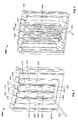
- Fig. 1 shows a perspective view of a first sealblock 1100 according to a first embodiment.
- the first sealblock 1100 may be part of a larger housing or case.
- the first sealblock 1100 may for example be a part of a building distributor box.
- the first sealblock 1100 may then serve for feeding through one or more filaments through a wall of the box.
- the filaments may for example be optical fibers or electric cables.
- the filaments may also be referred to as pigtails.
- the first sealblock 1100 may provide sealing against dust, dirt and humidity.
- the first sealblock 1100 may for example provide a sealing level of IP54 or higher.
- the first sealblock 1100 may allow to feed through 25 or more filaments.
- the first sealblock 1100 comprises a first body 1200 and two first fingers 1300. There may also be fewer or more than two first fingers 1300.
- the first fingers 1300 are arranged in a coplanar manner similar to the teeth of a comb. Since in the embodiment shown in Fig. 1 only two first fingers 1300 are provided, each first finger 1300 is also a marginal finger 305. If the first sealblock 1100 comprises three or more first fingers 1300, the two outermost first fingers 1300 are referred to as marginal fingers 305.
- Each first finger 1300 comprises an outer face 330 and an inner face 340. Only the outer face 330 is visible in Fig. 1 .
- the surface of the first sealblock 1100 that comprises the outer faces 330 of the first fingers 1300 may form an outer surface of a housing or case that comprises the first sealblock 1100.
- the first sealblock 1100 furthermore comprises three vertical slots 400 that are arranged vertically and in parallel to each other.
- a central slot 410 is arranged between two opposed side faces 310 of the two first fingers 1300.
- Two marginal slots 420 are arranged between a side face 310 of one first finger 1300 and a body side face 210 of the first body 1200, respectively.
- the body side faces 210 and the side faces 310 of the first fingers 1300 are all arranged in parallel with each other.
- Each slot 400 comprises an open upper end 430 and a closed lower end 440.
- Two first foam strips 1320 are arranged in each of the slots 400, respectively.
- one first foam strip 1320 is attached to the body side face 210
- the other first foam strip 1320 is attached to the opposing side face 310 of one first finger 1300.
- one first foam strip 1320 is arranged on one side face 310 of one first finger 1300
- the second first foam strip 1320 is arranged on the opposing side face 310 of the adjacent first finger 1300.
- the first foam strips 1320 may preferentially be glued on the side faces 210, 310.
- the first foam strips 1320 may for example be glued on the side faces 210, 310 with an adhesive tape.
- the first foam strips 1320 can be replaced in case they have grown old.
- the two opposing first foam strips 1320 in one slot 400 are in contact with one another.
- Fig. 1 further shows a filament 500 that is arranged near the lower end 440 of one of the slots 400.
- the filament 500 may be a pigtail, for example an optical fiber or an electric cable.
- the filament 500 has been introduced to the slot 400 from the upper end 430 of the slot 400.
- the first foam strips 1320 arranged in that slot 400 are therefore resiliently compressible.
- the first foam strips 1320 in the slot 400 enclose the filament 500 tightly, thereby providing sealing.
- Further filaments 500 may be introduced to the same slot 400 such that the individual filaments 500 are stacked on top of each other. Each of the filaments 500 then extends approximately perpendicular to the plane of the first fingers 1300.
- Further filaments 500 may be introduced to the other slots 400 of the first sealblock 1000.
- the first sealblock 1000 may comprise space for 25 or more filaments 500 in each of the slots 400.
- adding the filaments 500 to the slots 400 is very easy and requires no additional tools. Furthermore, no additional foam is needed on the filaments 500 for sealing the first
- Fig. 2 shows a rear view of the first sealblock 1000 of Fig. 1.
- Fig. 2 shows that the two first fingers 1300 are partially hollow with an open inner face 340.
- Fig. 2 furthermore shows that also the first body 1200 is partially hollow.
- a plurality of fins may arranged to improve stability of the first fingers 1300.
- the fins may be arranged perpendicular to the plane of the first fingers 1300 and the slots 400.
- the hollow body 1200 may also comprise fins for stabilization. Fins may however be omitted and are not shown in Fig. 2 .
- the first fingers 1300 and the first body 1200 may also be designed to be massive.
- the first fingers 1300 of the first sealblock 1100 are removable from the first body 1200.
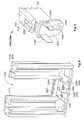
- Figs. 3 and 4 depict one of the first fingers 1300 separately, without ( Fig. 3 ) and with ( Fig. 4 ) the first foam strip 1320 attached.
- the first foam strips 1320 arranged on the two side faces 310 of the first finger 1300 are connected on an upper face 1360 of the first finger 1300.
- the first foam strip 1320 therefore comprises a U-shaped cross section.
- Figs. 1 and 2 show that the first foam strips 1320 arranged on the two body side faces 210 of the first body 1200 also extend slightly onto an upper surface of the first body 1200.
- An advantage of these arrangements of the first foam strips 1320 is that the upper ends 430 of the slots 400 of the first sealblock 1100 are slightly widened compared to the rest of the slots 400. This simplifies introducing filaments 500 into the slots 400.
- Fig. 5 depicts a first foot section 1370 at a lower end of one first finger 1300.
- the first foot section 1370 serves to connect the first finger 1300 to the first body 1200.
- the first foot section 1370 therefore comprises a bore 1380 that runs parallel to the longitudinal direction of the first finger 1300.
- the first foot section 1370 furthermore comprises a cut-out 1395 arranged on the lower end of the outer face 330 of the first finger 1300.
- the first finger 1300 furthermore comprises a first groove 1390 on the outer face 330 that runs normal to the longitudinal direction of the first finger 1300.
- Fig. 6 shows a rear view of the first body 1200 of the first sealblock 1100 with the first fingers 1300 removed.
- the first body 1200 comprises a clearance 1220 where the first fingers 1300 may be arranged.
- On a base section of the first body 1200 two tap holes 1280 are arranged.
- the bore 1380 of each first finger 1300 is aligned vertically above one tap hole 1280 of the first body 1200, such that the respective first finger 1300 can be fixated on the first body 1200 by means of a screw that runs through the bore 1380 into the tap hole 1280.
- the first body 1200 furthermore comprises two blocks 1295 and two first bulges 1290.
- the blocks 1295 are designed for mating with the cut-outs 1395 of the first fingers 1300.
- the first bulges 1290 are designed for mating with the first grooves 1390 of the first fingers 1300.
- These mechanisms and fixtures support placing and fixating the first fingers 1300 on the first body 1200 of the first sealblock 1100. It is possible to omit one or more elements of tap hole 1280, first bulge 1290, block 1295 and bore 1380, first groove 1390 and cut-out 1395, respectively.
- Fig. 7 shows a second finger 2300 of a second sealblock 2100 according to a second embodiment.
- Fig. 8 shows a second body 2200 of the second sealblock 2100.
- the second finger 2300 comprises a second foot section 2370 that comprises a second groove 2390 but no cut-out 1395. Accordingly, the second body 2200 comprises two second bulges 2290 for mating with the second grooves 2390 of the second fingers 2300, but no blocks 1295.
- the second foot section 2370 of the second finger 2300 furthermore comprises a bore 1380 that corresponds with a tap hole 1280 of the second body 2200.
- the second foot section 2370 of the second finger 2300 furthermore comprises two first pins 2380 that extend in the longitudinal direction of the second finger 2300.
- Each first pin 2380 approximately comprises a trapezoid cross section with a base face 2385 pointing outwards in the direction of the side faces 310 of the second finger 2300.
- the second body 2200 comprises a number of first openings 2280 for receiving the first pins 2380.
- Two marginal first openings 2286 are designed for receiving one first pin 2380 of one second finger 2300 respectively and therefore comprise an approximately trapezoid cross section.
- a central first opening 2285 is designed for receiving one first pin 2380 of one second finger 2300 and one first pin 2380 of an adjacent second finger 2300 and therefore comprises a hexagonal cross section.
- the first pins 2380 and the first opening 2280 may also be designed differently.
- the first pins 2380 might comprise semi-circular cross sections.
- the marginal first openings 2286 would then also comprise semi-circular cross sections.
- the central first opening 2285 would comprise a circular cross section.
- the side faces 310 of the second fingers 2300 and the body side faces 210 of the second body 2200 will again be provided with first foam strips 1320 or first foam strips 1320 before mounting the second fingers 2300 on the second body 2200.
- the foam strips arranged on the two side faces 310 of one second finger 2300 may be connected on an upper face 1360 of the second finger 2300 as in the first sealblock 1100.
- the two side faces 310 of one second finger 2300 may be equipped with separate foam strips.
- Fig. 9 shows a third foot section 3370 of a third finger 3300 of a third sealblock 3100 according to a third embodiment.
- Fig. 10 shows a corresponding third body 3200 of the third sealblock 3100.
- Fig. 11 shows a cross section through the third sealblock 3100 with the third body 3200 mated with two third fingers 3300.
- the third foot section 3370 of the third finger 3300 comprises a second groove 2390 like the second finger 2300.
- the third body 3200 accordingly comprises two second bulges 2290 for mating with the second grooves 2390 of two third fingers 3300.
- the third foot section 3370 of the third finger 3300 furthermore comprises two second pins 3380 that extend in the longitudinal direction of the third finger 3300.
- Each of the second pins 3380 comprises an approximately flat cuboid shape with a first barb 3385 arranged on the free end of each second pin 3380.
- the third body 3200 comprises four second openings 3280 for receiving the four second pins 3380 of two third fingers 3300.
- the cross section of Fig. 11 shows that the first barb 3385 of each second pin 3380 latches below an anchor 3285 in each of the second openings 3280.
- the second pins 3380 and the second openings 3280 therefore provide a snap-fit connection between the third fingers 3300 and the third body 3200.
- the third fingers 3300 again provide bores 1380 that correspond with tap holes 1280 of the third body 3200 for screwing the third fingers 3300 and the third body 3200 together. Either the bores 1380 and tap holes 1280 or the second pins 3380 and second openings 3280 may be omitted.
- the third finger 3300 furthermore comprises a notch 3330 arranged on a lower end of the outer face 330.
- the third body 3200 accordingly comprises two third pins 3290 that extend parallel to the plane of the third fingers 3300 into the second opening 3280.
- Each third pin 3290 comprises a second barb 3295 arranged on a free upper end of the third pin 3290.
- the third pins 3290 and the notch 3330 together provide a snap-fit connection that fixates the third finger 3300 on the third body 3200.
- the third pins 3290 and the notches 3330 may also be omitted, however.
- second foam strips 3320 will be arranged on each side face 310 of each third finger 3300 and on the two body side faces 210 of the third body 3200.
- Fig. 11 schematically shows that the second foam strips 3320 arranged on two opposing side faces 310 of two adjacent third fingers 3300, as well as two second foam strips 3320 arranged on a side face 310 of a third finger 3300 and an opposing body side face 210 of the third body 3200, do not necessarily need to be in contact with each other. It is, however, preferred that the two second foam strips 3320 in each slot 400 are in contact with one another to provide sealing.
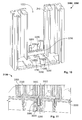
- Figs. 12 and 13 show a fourth finger 4300 of a fourth sealblock 4100 according to a fourth embodiment.
- Fig. 14 shows a perspective view of the fourth sealblock 4100 with a fourth body 4200 and two fourth fingers 4300.
- Each fourth finger 4300 comprises a second foot section 2370 like the second finger 2300.
- the fourth finger 4300 comprises an open outer face 4330 and a closed inner face 4340.
- the open outer face 4330 is open towards a hollow interior of the fourth finger 4300.
- a plurality of fins 4350 are arranged that extend perpendicular to the longitudinal direction of the fourth finger 4300.
- Fig. 14 shows that the fourth body 4200 also comprises a number of cavities 4220 on the outer surface.
- the fourth sealblock 4100 according to the fourth embodiment therefore comprises an open outer surface and a closed inner surface. Under certain conditions this may be preferable for molding the fourth fingers 4300 and the fourth body 4200 of the fourth sealblock 4100.
- a sealblock according to the invention comprises vertical slots that are arranged between opposing side faces of vertical fingers and/or between side faces of a finger and a body of the sealblock.
- the fingers are detachable from the body and may be connected to the body by means of a snap-on connection.
- resiliently compressible foam strips are arranged on each two side faces defining one slot.
- the slots are provided for receiving intermediate portions of filaments that run normal to the plane of the fingers.
- the filaments may be slided into the slots from an open upper end of each slot.
- Several filaments can be stacked on top of each other in each of the slots.
- the foam strips provide a sealing of the slots.
- adding additional filaments is easy and does not require any additional foam for sealing the filaments in the slots.
Landscapes
- Engineering & Computer Science (AREA)
- Power Engineering (AREA)
- Extrusion Moulding Of Plastics Or The Like (AREA)
Abstract
An apparatus for feeding through at least one filament comprises a body and at least one finger arranged in a clearance of the body. The finger has a side face adverse to a side face of the body. The side face of the finger and the side face of the body define between them a slot for receiving the filament. A foam strip is attached on at least one of the side faces defining the slot. The finger can be separated from the body.
Description
- The invention relates to an apparatus for feeding through at least one filament according to claim 1.
- For many applications it is necessary to feed filaments through a wall of a box or a casing. The filaments may for example be optical fibers or electric cables. The document
EP 0 531 172 B1 describes a possible feedthrough. Similar arrangements are also known for fixating filaments inside a casing. Such arrangements are described in the documentsUS 2008/0042536 A1 andEP 0 368 442 A2 . - It is an object of the present invention to provide an improved apparatus for feeding through at least one filament. This objective is achieved by an apparatus according to claim 1. Preferred embodiments are disclosed in the dependent claims.
- According to the invention, an apparatus for feeding through at least one filament comprises a body and at least one finger arranged in a clearance of the body. The finger has a side face adverse to a side face of the body. The side face of the finger and the side face of the body define between them a slot for receiving the filament. A foam strip is attached on at least one of the side faces defining the slot. Furthermore, the finger can be separated from the body. Advantageously, this apparatus allows for feeding through a large number of filaments. Another advantage is that the apparatus may provide a sealing level of IP54 or higher. A further advantage is that the detachable finger allows for a simple replacement of the foam strip.
- Preferably, the apparatus comprises a plurality of coplanar fingers. Opposed side faces of two adjacent fingers define between them an additional slot. A foam strip is attached on at least one of the side faces defining the additional slot. Advantageously, the apparatus then provides space for feeding through an even higher number of filaments.
- It is advisable that two side faces defining one slot both comprise foam strips and that these foam strips on opposed side faces of one slot are in contact with one another. The foam strips will then hold the filaments firmly and prevent dust and humidity from passing through the slot.
- Preferably, the foam strips provide a sealing of the slot. A sealing level of IP54 or higher may be provided. This can conveniently be achieved by designing the foam strips to be resiliently compressible. This furthermore allows for an easy placement of the filaments.
- In one embodiment of the invention, the at least one foam strip is glued on a side face. This allows for easy manufacture of the apparatus.
- Preferentially, the slots are designed for receiving an intermediate portion of the filament, the filament extending normal to the plane of the fingers.
- According to a further development, foam strips on opposed side faces of one finger are connected on an upper face of the finger. This simplifies manufacture of the apparatus and also simplifies introducing the filament in the slot.
- In a further improved embodiment of the apparatus, at least one finger can be connected to the body by means of a snap-on connection. This allows for an easy mounting and demounting of the finger.
- It is convenient that a foot section of at least one finger comprises a bore and the body comprises a corresponding tap hole. Advantageously this allows for fixating the finger on the body.
- In one embodiment of the apparatus, the foot section of at least one finger comprises a groove and the body comprises a bulge designed for mating with the groove. Advantageously, this simplifies aligning the finger on the body.
- In one embodiment of the apparatus, the foot section of at least one finger comprises a cut-out and the body comprises a block designed for mating with the cut-out. This also helps with aligning the finger on the body and with fixating the finger on the body.
- In one embodiment, the foot section of at least one finger comprises a first pin and the body comprises an opening for receiving the first pin. Also this arrangement simplifies alignment of the finger on the body and fixates the finger on the body.
- In a preferred embodiment, the first pin comprises a first barb for latching in the opening. This allows for a stronger fixation of the finger on the body.
- In one embodiment of the apparatus, at least one finger comprises a notch and the body comprises a second pin with a second barb for mating with the notch. This also helps fixating the finger on the body.
- In a further improved embodiment, the fingers are at least partially hollow. This simplifies molding the fingers, reduces the weight of the fingers and reduces the amount of material necessary for producing the fingers.
- The invention will now be explained in greater detail with reference to the Figures in which
-
Fig. 1 shows a perspective view of an apparatus according to a first embodiment; -
Fig. 2 shows a rear view of the apparatus; -
Fig. 3 shows a finger according to the first embodiment; -
Fig. 4 shows the finger with a foam strip attached; -
Fig. 5 shows a detail of the finger; -
Fig. 6 shows a body of the apparatus according to the first embodiment; -
Fig. 7 shows a finger of an apparatus according to a second embodiment; -
Fig. 8 shows a body of the apparatus according to the second embodiment; -
Fig. 9 shows a detail of a finger according to a third embodiment; -
Fig. 10 shows a body of the apparatus according to the third embodiment; -
Fig. 11 shows a cross section of the apparatus according to the third embodiment; -
Fig. 12 shows a finger of an apparatus according to a fourth embodiment; -
Fig. 13 shows another view of the finger; and -
Fig. 14 shows a perspective view of the apparatus according to the fourth embodiment. -
Fig. 1 shows a perspective view of afirst sealblock 1100 according to a first embodiment. Thefirst sealblock 1100 may be part of a larger housing or case. Thefirst sealblock 1100 may for example be a part of a building distributor box. Thefirst sealblock 1100 may then serve for feeding through one or more filaments through a wall of the box. The filaments may for example be optical fibers or electric cables. The filaments may also be referred to as pigtails. Thefirst sealblock 1100 may provide sealing against dust, dirt and humidity. Thefirst sealblock 1100 may for example provide a sealing level of IP54 or higher. Thefirst sealblock 1100 may allow to feed through 25 or more filaments. - The
first sealblock 1100 comprises afirst body 1200 and twofirst fingers 1300. There may also be fewer or more than twofirst fingers 1300. Thefirst fingers 1300 are arranged in a coplanar manner similar to the teeth of a comb. Since in the embodiment shown inFig. 1 only twofirst fingers 1300 are provided, eachfirst finger 1300 is also amarginal finger 305. If thefirst sealblock 1100 comprises three or morefirst fingers 1300, the two outermostfirst fingers 1300 are referred to asmarginal fingers 305. - Each
first finger 1300 comprises anouter face 330 and aninner face 340. Only theouter face 330 is visible inFig. 1 . The surface of thefirst sealblock 1100 that comprises the outer faces 330 of thefirst fingers 1300 may form an outer surface of a housing or case that comprises thefirst sealblock 1100. - The
first sealblock 1100 furthermore comprises threevertical slots 400 that are arranged vertically and in parallel to each other. Acentral slot 410 is arranged between two opposed side faces 310 of the twofirst fingers 1300. Twomarginal slots 420 are arranged between aside face 310 of onefirst finger 1300 and a body side face 210 of thefirst body 1200, respectively. The body side faces 210 and the side faces 310 of thefirst fingers 1300 are all arranged in parallel with each other. Eachslot 400 comprises an openupper end 430 and a closedlower end 440. - Two
first foam strips 1320 are arranged in each of theslots 400, respectively. In themarginal slots 420, onefirst foam strip 1320 is attached to thebody side face 210, the otherfirst foam strip 1320 is attached to the opposingside face 310 of onefirst finger 1300. In thecentral slot 410, onefirst foam strip 1320 is arranged on oneside face 310 of onefirst finger 1300, while the secondfirst foam strip 1320 is arranged on the opposingside face 310 of the adjacentfirst finger 1300. Thefirst foam strips 1320 may preferentially be glued on the side faces 210, 310. Thefirst foam strips 1320 may for example be glued on the side faces 210, 310 with an adhesive tape. Preferentially, thefirst foam strips 1320 can be replaced in case they have grown old. Preferentially, the two opposingfirst foam strips 1320 in oneslot 400 are in contact with one another. -
Fig. 1 further shows afilament 500 that is arranged near thelower end 440 of one of theslots 400. Thefilament 500 may be a pigtail, for example an optical fiber or an electric cable. Thefilament 500 has been introduced to theslot 400 from theupper end 430 of theslot 400. Thefirst foam strips 1320 arranged in thatslot 400 are therefore resiliently compressible. Thefirst foam strips 1320 in theslot 400 enclose thefilament 500 tightly, thereby providing sealing.Further filaments 500 may be introduced to thesame slot 400 such that theindividual filaments 500 are stacked on top of each other. Each of thefilaments 500 then extends approximately perpendicular to the plane of thefirst fingers 1300.Further filaments 500 may be introduced to theother slots 400 of the first sealblock 1000. The first sealblock 1000 may comprise space for 25 ormore filaments 500 in each of theslots 400. Advantageously, adding thefilaments 500 to theslots 400 is very easy and requires no additional tools. Furthermore, no additional foam is needed on thefilaments 500 for sealing the first sealblock 1000. -
Fig. 2 shows a rear view of the first sealblock 1000 ofFig. 1. Fig. 2 shows that the twofirst fingers 1300 are partially hollow with an openinner face 340.Fig. 2 furthermore shows that also thefirst body 1200 is partially hollow. In the hollow space of each first finger 1300 a plurality of fins may arranged to improve stability of thefirst fingers 1300. The fins may be arranged perpendicular to the plane of thefirst fingers 1300 and theslots 400. Thehollow body 1200 may also comprise fins for stabilization. Fins may however be omitted and are not shown inFig. 2 . Thefirst fingers 1300 and thefirst body 1200 may also be designed to be massive. - The
first fingers 1300 of thefirst sealblock 1100 are removable from thefirst body 1200.Figs. 3 and 4 depict one of thefirst fingers 1300 separately, without (Fig. 3 ) and with (Fig. 4 ) thefirst foam strip 1320 attached. Thefirst foam strips 1320 arranged on the two side faces 310 of thefirst finger 1300 are connected on anupper face 1360 of thefirst finger 1300. Thefirst foam strip 1320 therefore comprises a U-shaped cross section.Figs. 1 and 2 show that thefirst foam strips 1320 arranged on the two body side faces 210 of thefirst body 1200 also extend slightly onto an upper surface of thefirst body 1200. An advantage of these arrangements of thefirst foam strips 1320 is that the upper ends 430 of theslots 400 of thefirst sealblock 1100 are slightly widened compared to the rest of theslots 400. This simplifies introducingfilaments 500 into theslots 400. -
Fig. 5 depicts afirst foot section 1370 at a lower end of onefirst finger 1300. Thefirst foot section 1370 serves to connect thefirst finger 1300 to thefirst body 1200. Thefirst foot section 1370 therefore comprises abore 1380 that runs parallel to the longitudinal direction of thefirst finger 1300. Thefirst foot section 1370 furthermore comprises a cut-out 1395 arranged on the lower end of theouter face 330 of thefirst finger 1300. Thefirst finger 1300 furthermore comprises afirst groove 1390 on theouter face 330 that runs normal to the longitudinal direction of thefirst finger 1300. -
Fig. 6 shows a rear view of thefirst body 1200 of thefirst sealblock 1100 with thefirst fingers 1300 removed. Thefirst body 1200 comprises aclearance 1220 where thefirst fingers 1300 may be arranged. On a base section of thefirst body 1200 twotap holes 1280 are arranged. When thefirst fingers 1300 are arranged on thefirst body 1200, thebore 1380 of eachfirst finger 1300 is aligned vertically above onetap hole 1280 of thefirst body 1200, such that the respectivefirst finger 1300 can be fixated on thefirst body 1200 by means of a screw that runs through thebore 1380 into thetap hole 1280. - The
first body 1200 furthermore comprises twoblocks 1295 and twofirst bulges 1290. Theblocks 1295 are designed for mating with the cut-outs 1395 of thefirst fingers 1300. Thefirst bulges 1290 are designed for mating with thefirst grooves 1390 of thefirst fingers 1300. Together these mechanisms and fixtures support placing and fixating thefirst fingers 1300 on thefirst body 1200 of thefirst sealblock 1100. It is possible to omit one or more elements oftap hole 1280,first bulge 1290,block 1295 and bore 1380,first groove 1390 and cut-out 1395, respectively. -
Fig. 7 shows a second finger 2300 of a second sealblock 2100 according to a second embodiment.Fig. 8 shows a second body 2200 of the second sealblock 2100. - In contrast to the
first fingers 1300 the second finger 2300 comprises asecond foot section 2370 that comprises asecond groove 2390 but no cut-out 1395. Accordingly, the second body 2200 comprises twosecond bulges 2290 for mating with thesecond grooves 2390 of the second fingers 2300, but noblocks 1295. - Just like the
first finger 1300, thesecond foot section 2370 of the second finger 2300 furthermore comprises abore 1380 that corresponds with atap hole 1280 of the second body 2200. - The
second foot section 2370 of the second finger 2300 furthermore comprises twofirst pins 2380 that extend in the longitudinal direction of the second finger 2300. Eachfirst pin 2380 approximately comprises a trapezoid cross section with abase face 2385 pointing outwards in the direction of the side faces 310 of the second finger 2300. - The second body 2200 comprises a number of first openings 2280 for receiving the first pins 2380. Two marginal first openings 2286 are designed for receiving one
first pin 2380 of one second finger 2300 respectively and therefore comprise an approximately trapezoid cross section. A central first opening 2285 is designed for receiving onefirst pin 2380 of one second finger 2300 and onefirst pin 2380 of an adjacent second finger 2300 and therefore comprises a hexagonal cross section. - The
first pins 2380 and the first opening 2280 may also be designed differently. For example, thefirst pins 2380 might comprise semi-circular cross sections. The marginal first openings 2286 would then also comprise semi-circular cross sections. The central first opening 2285 would comprise a circular cross section. - The side faces 310 of the second fingers 2300 and the body side faces 210 of the second body 2200 will again be provided with
first foam strips 1320 orfirst foam strips 1320 before mounting the second fingers 2300 on the second body 2200. The foam strips arranged on the two side faces 310 of one second finger 2300 may be connected on anupper face 1360 of the second finger 2300 as in thefirst sealblock 1100. Alternatively, the two side faces 310 of one second finger 2300 may be equipped with separate foam strips. -
Fig. 9 shows athird foot section 3370 of athird finger 3300 of athird sealblock 3100 according to a third embodiment.Fig. 10 shows a correspondingthird body 3200 of thethird sealblock 3100.Fig. 11 shows a cross section through thethird sealblock 3100 with thethird body 3200 mated with twothird fingers 3300. - The
third foot section 3370 of thethird finger 3300 comprises asecond groove 2390 like the second finger 2300. Thethird body 3200 accordingly comprises twosecond bulges 2290 for mating with thesecond grooves 2390 of twothird fingers 3300. - The
third foot section 3370 of thethird finger 3300 furthermore comprises twosecond pins 3380 that extend in the longitudinal direction of thethird finger 3300. Each of thesecond pins 3380 comprises an approximately flat cuboid shape with afirst barb 3385 arranged on the free end of eachsecond pin 3380. - Accordingly, the
third body 3200 comprises foursecond openings 3280 for receiving the foursecond pins 3380 of twothird fingers 3300. The cross section ofFig. 11 shows that thefirst barb 3385 of eachsecond pin 3380 latches below ananchor 3285 in each of thesecond openings 3280. Thesecond pins 3380 and thesecond openings 3280 therefore provide a snap-fit connection between thethird fingers 3300 and thethird body 3200. - In addition, the
third fingers 3300 again providebores 1380 that correspond withtap holes 1280 of thethird body 3200 for screwing thethird fingers 3300 and thethird body 3200 together. Either thebores 1380 and tapholes 1280 or thesecond pins 3380 andsecond openings 3280 may be omitted. - The
third finger 3300 furthermore comprises anotch 3330 arranged on a lower end of theouter face 330. Thethird body 3200 accordingly comprises twothird pins 3290 that extend parallel to the plane of thethird fingers 3300 into thesecond opening 3280. Eachthird pin 3290 comprises asecond barb 3295 arranged on a free upper end of thethird pin 3290. When athird finger 3300 is arranged on thethird body 3200, thethird pins 3290 and thenotch 3330 together provide a snap-fit connection that fixates thethird finger 3300 on thethird body 3200. Thethird pins 3290 and thenotches 3330 may also be omitted, however. - Again,
second foam strips 3320 will be arranged on each side face 310 of eachthird finger 3300 and on the two body side faces 210 of thethird body 3200.Fig. 11 schematically shows that thesecond foam strips 3320 arranged on two opposing side faces 310 of two adjacentthird fingers 3300, as well as twosecond foam strips 3320 arranged on aside face 310 of athird finger 3300 and an opposing body side face 210 of thethird body 3200, do not necessarily need to be in contact with each other. It is, however, preferred that the twosecond foam strips 3320 in eachslot 400 are in contact with one another to provide sealing. -
Figs. 12 and 13 show afourth finger 4300 of afourth sealblock 4100 according to a fourth embodiment.Fig. 14 shows a perspective view of thefourth sealblock 4100 with afourth body 4200 and twofourth fingers 4300. - Each
fourth finger 4300 comprises asecond foot section 2370 like the second finger 2300. - In contrast to the
fingers fourth finger 4300 comprises an openouter face 4330 and a closedinner face 4340. The openouter face 4330 is open towards a hollow interior of thefourth finger 4300. In the hollow space of the fourth finger 4300 a plurality offins 4350 are arranged that extend perpendicular to the longitudinal direction of thefourth finger 4300. -
Fig. 14 shows that thefourth body 4200 also comprises a number ofcavities 4220 on the outer surface. Compared to thefirst sealblock 1100 according to the second embodiment shown inFigs. 1 and 2 , thefourth sealblock 4100 according to the fourth embodiment therefore comprises an open outer surface and a closed inner surface. Under certain conditions this may be preferable for molding thefourth fingers 4300 and thefourth body 4200 of thefourth sealblock 4100. - In summary, a sealblock according to the invention comprises vertical slots that are arranged between opposing side faces of vertical fingers and/or between side faces of a finger and a body of the sealblock. The fingers are detachable from the body and may be connected to the body by means of a snap-on connection. On each two side faces defining one slot, resiliently compressible foam strips are arranged. The slots are provided for receiving intermediate portions of filaments that run normal to the plane of the fingers. The filaments may be slided into the slots from an open upper end of each slot. Several filaments can be stacked on top of each other in each of the slots. The foam strips provide a sealing of the slots. Advantageously, adding additional filaments is easy and does not require any additional foam for sealing the filaments in the slots.
Claims (15)
- Apparatus (1100, 2100, 3100, 4100) for feeding through at least one filament (500),
the apparatus (1100, 2100, 3100, 4100) comprising a body (1200, 2200, 3200, 4200)
and at least one finger (1300, 2300, 3300, 4300) arranged in a clearance (1220) of the body (1200, 2200, 3200, 4200),
the finger (1300, 2300, 3300, 4300) having a side face (310) adverse to a side face (210) of the body (1200, 2200, 3200, 4200),
wherein the side face (310) of the finger (1300, 2300, 3300, 4300) and the side face (210) of the body (1200, 2200, 3200, 4200) define between them a slot (400, 420) for receiving the filament (500),
wherein a foam strip (1320, 3320) is attached on at least one of the side faces (210, 310) defining the slot (400, 420),
characterized in that
the finger (1300, 2300, 3300, 4300) can be separated from the body (1200, 2200, 3200, 4200). - The apparatus (1100, 2100, 3100, 4100) according to claim 1,
characterized in that
the apparatus (1100, 2100, 3100, 4100) comprises a plurality of coplanar fingers (1300, 2300, 3300, 4300) ,
wherein opposed side faces (310) of two adjacent fingers (1300, 2300, 3300, 4300) define between them an additional slot (400, 410),
wherein a foam strip (1320, 3320) is attached on at least one of the side faces (310) defining the additional slot (400, 410). - The apparatus (1100, 2100, 3100, 4100) according to any one of claims 1 or 2,
characterized in that
two side faces (210, 310) defining one slot (400) both comprise foam strips (1320, 3320),
wherein these foam strips (1320, 3320) are in contact with one another. - The apparatus (1100, 2100, 3100, 4100) according to claim 3,
characterized in that
the foam strips (1320, 3320) provide a sealing of the slot (400). - The apparatus (1100, 2100, 3100, 4100) according to any one of claims 1 to 4,
characterized in that
at least one foam strip (1320, 3320) is glued on a side face (310, 210). - The apparatus (1100, 2100, 3100, 4100) according to any one of claims 1 to 5,
characterized in that
the slots (400) are designed for receiving an intermediate portion of the filament (500),
wherein the filament (500) extends normal to the plane of the fingers (1300, 2300, 3300, 4300). - The apparatus (1100, 2100, 3100, 4100) according to any one of claims 1 to 6,
characterized in that
foam strips (1320, 3320) on opposed side faces (310) of one finger (1300, 2300, 3300, 4300) are connected on an upper face (1360) of the finger (1300, 2300, 3300, 4300). - The apparatus (1100, 2100, 3100, 4100) according to any one of claims 1 to 7,
characterized in that
at least one finger (1300, 2300, 3300, 4300) can be connected to the body (1200, 2200, 3200, 4200) by means of a snap-on connection. - The apparatus (1100, 2100, 3100, 4100) according to any one of claims 1 to 8,
characterized in that
a foot section (1370, 2370, 3370) of at least one finger (1300, 2300, 3300, 4300) comprises a bore (1380),
wherein the body (1200, 2200, 3200, 4200) comprises a corresponding tap hole (1280). - The apparatus (1100, 2100, 3100, 4100) according to any one of claims 1 to 9,
characterized in that
a foot section (1370, 2370, 3370) of at least one finger (1300, 2300, 3300, 4300) comprises a groove (1390, 2390),
wherein the body (1200, 2200, 3200, 4200) comprises a bulge (1290, 2290) designed for mating with the groove (1390, 2390). - The apparatus (1100) according to any one of claims 1 to 10,
characterized in that
a foot section (1370) of at least one finger (1300) comprises a cut-out (1395),
wherein the body (1200) comprises a block (1295) designed for mating with the cut-out (1395). - The apparatus (2100, 3100, 4100) according to any one of claims 1 to 11,
characterized in that
a foot section (2370, 3370) of at least one finger (2300, 3300, 4300) comprises a first pin (2380, 3380),
wherein the body (2200, 3200, 4200) comprises an opening (2280, 3280) for receiving the first pin (2380, 3380). - The apparatus (3100) according to claim 12, characterized in that
the first pin (3380) comprises a first barb (3385) for latching in the opening (3280). - The apparatus (3100) according to any one of claims 1 to 13,
characterized in that
at least one finger (3300) comprises a notch (3330), wherein the body (3200) comprises a second pin (3290) with a second barb (3295) for mating with the notch (3330) . - The apparatus (1100, 2100, 3100, 4100) according to any one of claims 1 to 14,
characterized in that
at least one finger (1300, 2300, 3300, 4300) is at least partially hollow.
Priority Applications (1)
| Application Number | Priority Date | Filing Date | Title |
|---|---|---|---|
| EP10173024A EP2421104A1 (en) | 2010-08-17 | 2010-08-17 | Cable feedthrough |
Applications Claiming Priority (1)
| Application Number | Priority Date | Filing Date | Title |
|---|---|---|---|
| EP10173024A EP2421104A1 (en) | 2010-08-17 | 2010-08-17 | Cable feedthrough |
Publications (1)
| Publication Number | Publication Date |
|---|---|
| EP2421104A1 true EP2421104A1 (en) | 2012-02-22 |
Family
ID=43446641
Family Applications (1)
| Application Number | Title | Priority Date | Filing Date |
|---|---|---|---|
| EP10173024A Withdrawn EP2421104A1 (en) | 2010-08-17 | 2010-08-17 | Cable feedthrough |
Country Status (1)
| Country | Link |
|---|---|
| EP (1) | EP2421104A1 (en) |
Citations (5)
| Publication number | Priority date | Publication date | Assignee | Title |
|---|---|---|---|---|
| DE2720936A1 (en) * | 1977-05-10 | 1978-11-23 | Ewald Nelken | Watertight cable connection into cabinet - has split halves with sealing pads to sandwich cables and apply sealing pressure |
| EP0368442A2 (en) | 1988-11-08 | 1990-05-16 | Pioneer Electronic Corporation | Optical information record carrier and the method of producing the same |
| EP0531172B1 (en) | 1991-09-06 | 1996-07-24 | THOMAS & BETTS CORPORATION | An enclosure for an electrical terminal block including barrier means for a cable entry opening |
| DE19961244C1 (en) * | 1999-12-18 | 2001-01-25 | Loh Kg Rittal Werk | Electrical or electronic apparatus housing has cable opening fitted with cooperating cable guides provided with seatings for reception of cable sealing elements |
| US20080042536A1 (en) | 2006-08-21 | 2008-02-21 | Afl Telecommunications Llc. | Strain relief system |
-
2010
- 2010-08-17 EP EP10173024A patent/EP2421104A1/en not_active Withdrawn
Patent Citations (5)
| Publication number | Priority date | Publication date | Assignee | Title |
|---|---|---|---|---|
| DE2720936A1 (en) * | 1977-05-10 | 1978-11-23 | Ewald Nelken | Watertight cable connection into cabinet - has split halves with sealing pads to sandwich cables and apply sealing pressure |
| EP0368442A2 (en) | 1988-11-08 | 1990-05-16 | Pioneer Electronic Corporation | Optical information record carrier and the method of producing the same |
| EP0531172B1 (en) | 1991-09-06 | 1996-07-24 | THOMAS & BETTS CORPORATION | An enclosure for an electrical terminal block including barrier means for a cable entry opening |
| DE19961244C1 (en) * | 1999-12-18 | 2001-01-25 | Loh Kg Rittal Werk | Electrical or electronic apparatus housing has cable opening fitted with cooperating cable guides provided with seatings for reception of cable sealing elements |
| US20080042536A1 (en) | 2006-08-21 | 2008-02-21 | Afl Telecommunications Llc. | Strain relief system |
Similar Documents
| Publication | Publication Date | Title |
|---|---|---|
| US10670821B2 (en) | Optical fiber organizer with trays mounted on pivoting support | |
| US6687450B1 (en) | Break-out device | |
| US6504986B1 (en) | Optical fiber assembly | |
| EP2074833B1 (en) | Release latch for pre-terminated cassette | |
| AU2010282782B9 (en) | Fiber management component | |
| US20230164257A1 (en) | Tray tower with position indexing trays | |
| KR20080033420A (en) | Fiber optical adapter module | |
| US8221169B2 (en) | Fanning module, fanning strip, and cable management panel | |
| BR112019019485A2 (en) | connectors for a single twisted pair of conductors, adapter, and harnesses | |
| JP2013047804A (en) | Optical fiber connector | |
| US9075220B2 (en) | Optical fiber module with mounting block for securing an optical fiber connector | |
| RU2592729C2 (en) | Cable plug assembly | |
| US9407073B2 (en) | Guiding support and kit for terminating a transmission cable | |
| EP2538508A1 (en) | Sealing device for feeding through filaments | |
| TW202040191A (en) | Optical fiber adapter | |
| KR20040002944A (en) | Optical fibre termination unit | |
| JP5744628B2 (en) | Optical fiber connection structure | |
| EP1181604A1 (en) | Break-out device | |
| JP5100328B2 (en) | Fiber optic cable fixture | |
| US20240218929A1 (en) | Seal for a port of an enclosure configured to permit a pre-connectorized cable to be inserted into and removed from the seal with a connector attached to the cable | |
| EP2302430A1 (en) | Device for receiving subassemblies assigned to at least one optical fiber cable and for fastening the same to a mounting | |
| US20250060052A1 (en) | Retainer for a port of an enclosure configured to grip a cable so as to limit tension strain on the cable | |
| US8469723B2 (en) | Re-configurable electrical connectors | |
| TW202544503A (en) | Adapter and its assembly method | |
| KR101506515B1 (en) | Fiber Distribution Frame with Extension Capability |
Legal Events
| Date | Code | Title | Description |
|---|---|---|---|
| AK | Designated contracting states |
Kind code of ref document: A1 Designated state(s): AL AT BE BG CH CY CZ DE DK EE ES FI FR GB GR HR HU IE IS IT LI LT LU LV MC MK MT NL NO PL PT RO SE SI SK SM TR |
|
| AX | Request for extension of the european patent |
Extension state: BA ME RS |
|
| PUAI | Public reference made under article 153(3) epc to a published international application that has entered the european phase |
Free format text: ORIGINAL CODE: 0009012 |
|
| STAA | Information on the status of an ep patent application or granted ep patent |
Free format text: STATUS: THE APPLICATION IS DEEMED TO BE WITHDRAWN |
|
| 18D | Application deemed to be withdrawn |
Effective date: 20120823 |