EP2420904B1 - Einrichtung und Verfahren zur Konfiguration eines Steuerungssystems - Google Patents
Einrichtung und Verfahren zur Konfiguration eines Steuerungssystems Download PDFInfo
- Publication number
- EP2420904B1 EP2420904B1 EP10012240.7A EP10012240A EP2420904B1 EP 2420904 B1 EP2420904 B1 EP 2420904B1 EP 10012240 A EP10012240 A EP 10012240A EP 2420904 B1 EP2420904 B1 EP 2420904B1
- Authority
- EP
- European Patent Office
- Prior art keywords
- hardware
- configuration
- configuration field
- access points
- functionalities
- Prior art date
- Legal status (The legal status is an assumption and is not a legal conclusion. Google has not performed a legal analysis and makes no representation as to the accuracy of the status listed.)
- Active
Links
Images





Classifications
-
- G—PHYSICS
- G05—CONTROLLING; REGULATING
- G05B—CONTROL OR REGULATING SYSTEMS IN GENERAL; FUNCTIONAL ELEMENTS OF SUCH SYSTEMS; MONITORING OR TESTING ARRANGEMENTS FOR SUCH SYSTEMS OR ELEMENTS
- G05B19/00—Program-control systems
- G05B19/02—Program-control systems electric
- G05B19/04—Program control other than numerical control, i.e. in sequence controllers or logic controllers
- G05B19/042—Program control other than numerical control, i.e. in sequence controllers or logic controllers using digital processors
- G05B19/0426—Programming the control sequence
-
- G—PHYSICS
- G05—CONTROLLING; REGULATING
- G05B—CONTROL OR REGULATING SYSTEMS IN GENERAL; FUNCTIONAL ELEMENTS OF SUCH SYSTEMS; MONITORING OR TESTING ARRANGEMENTS FOR SUCH SYSTEMS OR ELEMENTS
- G05B2219/00—Program-control systems
- G05B2219/20—Pc systems
- G05B2219/23—Pc programming
- G05B2219/23258—GUI graphical user interface, icon, function bloc editor, labview
-
- G—PHYSICS
- G05—CONTROLLING; REGULATING
- G05B—CONTROL OR REGULATING SYSTEMS IN GENERAL; FUNCTIONAL ELEMENTS OF SUCH SYSTEMS; MONITORING OR TESTING ARRANGEMENTS FOR SUCH SYSTEMS OR ELEMENTS
- G05B2219/00—Program-control systems
- G05B2219/20—Pc systems
- G05B2219/23—Pc programming
- G05B2219/23273—Select, associate the real hardware to be used in the program
-
- G—PHYSICS
- G05—CONTROLLING; REGULATING
- G05B—CONTROL OR REGULATING SYSTEMS IN GENERAL; FUNCTIONAL ELEMENTS OF SUCH SYSTEMS; MONITORING OR TESTING ARRANGEMENTS FOR SUCH SYSTEMS OR ELEMENTS
- G05B2219/00—Program-control systems
- G05B2219/20—Pc systems
- G05B2219/23—Pc programming
- G05B2219/23274—Link graphical data for display automatically into program
-
- G—PHYSICS
- G05—CONTROLLING; REGULATING
- G05B—CONTROL OR REGULATING SYSTEMS IN GENERAL; FUNCTIONAL ELEMENTS OF SUCH SYSTEMS; MONITORING OR TESTING ARRANGEMENTS FOR SUCH SYSTEMS OR ELEMENTS
- G05B2219/00—Program-control systems
- G05B2219/20—Pc systems
- G05B2219/23—Pc programming
- G05B2219/23291—Process, graphic programming of a process, text and images
-
- G—PHYSICS
- G05—CONTROLLING; REGULATING
- G05B—CONTROL OR REGULATING SYSTEMS IN GENERAL; FUNCTIONAL ELEMENTS OF SUCH SYSTEMS; MONITORING OR TESTING ARRANGEMENTS FOR SUCH SYSTEMS OR ELEMENTS
- G05B2219/00—Program-control systems
- G05B2219/20—Pc systems
- G05B2219/23—Pc programming
- G05B2219/23292—Use of model of process, divided in part models with IN, OUT and actuator
Definitions
- the invention relates to a configuration device for configuring a control system having at least one electronic computer unit and at least one associated I / O device, wherein at least a part of a control program corresponding to the configuration for controlling the control system can be generated and wherein the configuration device has at least one display device, wherein at least one I / O access point in a model configuration field and at least one hardware functionality in a function configuration field and at least one hardware interface in an interface configuration field can be displayed by means of the display device, wherein at least one I / O access point and at least one hardware functionality can be assigned to one another and / or wherein at least one hardware functionality and at least one hardware interface are assignable to each other. Furthermore, the invention relates to a related computer program.
- control system is used below as a comprehensive term for a technical device, which is used essentially for the tasks of measuring, controlling, regulating, calibrating; In the broadest sense, this can be an electronic, programmable system. The term is not limited to what is narrowly defined in the system-theoretical sense as a control.
- An electronic control system of the type in question consists of at least one electronic computer unit, ie of a single or multiprocessor system, which is usually operated with a real-time operating system.
- This computer unit is connected to the process to be controlled via corresponding I / O devices.
- I / O devices are understood as meaning a large bandwidth of possible technical devices with one or more outside world interfaces.
- this also includes devices with intelligent signal processing for pre- and post-processing of data, data bus modules, devices for signal conditioning, but also, for example, power modules.
- An I / O device can technically form a separate unit that can be added to a computer unit (for example, internal bus slot in the computer unit, coupling via an external communication interface), but it can also be an integral part of a computer unit, eg. For example, if integrated in a processor I / O device functionality.
- the teaching of the invention is basically limited to any specific device-technical embodiment or dependent on such.
- a hardware functionality This may be, for example, a digital-analog or analog-to-digital converter, including but also complex parameterizable modules such. These include data buses (including the definition of the messages that can be transmitted and their timing behavior), digital signal processors (including the description for the generation / analysis of signal waveforms) or modules for pulse width modulation of signals.
- Modern control systems have a flexible hardware architecture that allows signals originating from a module with a particular hardware functionality to be routed within the control system over freely selectable signal paths (routing of signal paths).
- This is of particular interest for control systems which, in addition to elementary I / O devices, also include, for example, I / O devices for signal conditioning (for example conversion of current signals into voltage signals, conversion of input signals of a specific range into output signals of another range) and / or power modules (eg, output from high electrical currents or voltages).
- the functionality of the control system must be defined abstractly, ie, detached from the hardware properties of the control system.
- This functional development is usually assisted by mathematical design tools that allow a block diagram oriented design of the functionality to be implemented later on the control system.
- the result of the functional development is a mathematical model of the planned abstract functionality of the control system, in which, although all necessary input and output variables are abstractly known, the model has no relation to the hardware functionality and the hardware interfaces of the control system. While it is possible to use this model to generate a control program executable on the control system, such a control program can not access the hardware functionality and hardware interfaces of the control system because no such information is stored in the abstract model to configure the control system have been.
- From the EP 1 522 910 Al is another method for setting up and configuring a control system from which the present invention is based.
- this method the assignment of certain input and output variables of the abstract model to certain hardware functionalities and hardware interfaces as well as the parameterization and configuration of the hardware functionalities and hardware interfaces is no longer made in the abstract model, but this is done separately from the abstract model.
- only certain signals are designated as (symbolic) I / O access points, which merely means that these are signals that are output on the actual control system using a particular hardware functionality as a physical signal or as a physical signal read become.
- the assignment of the I / O access points of the model to hardware functionalities and hardware functionalities to hardware interfaces is independent of the model, the assignability of the various components of the control system is limited due to the textual, tabular method possible, the same applies to the orientation within the available components of the control system in the configuration or even in the detection of an existing configuration.
- the configuration device is advantageous over the prior art in many respects.
- Unlike a purely tabular representation of separate channels of a hardware unit - such.
- the channels of an A / D converter - is the block-oriented representation of elements of a configuration field structurally meaningful manner and thus supported by technical means the configurability of a control system quite considerably.
- the configuration device has the further advantage that elements of the various configuration fields, ie I / O access points of the model configuration field, hardware functionalities of the function configuration field or hardware interfaces of the interface configuration field, can be assigned in the block-oriented representation by graphical assignment means Configuration in a noticeable way is immediately recognizable which elements of the configuration fields have not yet been used in the context of the configuration and therefore still further in the establishment and configuration of the control system freely available. In addition, it is immediately apparent which associations have already been made between the elements of various configuration fields, whereby several associations can also be clearly and unambiguously represented and recognized at the same time.
- the possible and / or the actual signal directions of the I / O access points in the model configuration field and / or the hardware functionalities in the function configuration field and / or the hardware interfaces in the interface configuration field can be displayed with the input and output ports.
- This configuration of the configuration device automatically enables a tracking of the signal flows within the configured control system with the configuration device, which in turn is not possible with the table-like assignments known from the prior art.
- this measure helps to avoid misallocations between I / O access points, hardware functionalities and hardware interfaces, since the input or output character of the corresponding ports of the blocks is recognizable and thus, for example, the wrong assignment of outputs to outputs or from inputs to inputs obvious and automatically recognizable by the configuration device.
- the displayed contents of the model configuration field and / or the function configuration field and / or the interface configuration field are displaceable relative to one another such that mutually assigned or assignable I / O access points and / or hardware functionalities and / or hardware interfaces can be simultaneously displayed and thus assigned to one another / or are configurable together.
- the relative mobility of the contents can be exhausted, for example, in one direction of movement if the contents of the configuration fields are arranged in rows or columns.
- arbitrary partial contents of the various configuration fields can be brought into direct proximity to one another, so that they can be assigned to one another by graphic assignment means, in the present case being able to be connected to one another by signal lines.
- assignments made once again by signal lines between elements of different configuration fields can also be maintained during the relative movement of contents of these fields by elastically following the signal lines of the relative movement. Neighboring the contents of various configuration fields also ensures that I / O access point configurations, hardware functionalities, and hardware interfaces are reconcilable as they can be viewed and matched at the same time.
- the configuration device is configured such that at least one selected I / O access point in the model configuration field or at least one hardware functionality in the function configuration field or at least one hardware interface in the interface configuration field assigns the assigned and / or assignable I / O access points and / or. or hardware functionalities and / or hardware interfaces are automatically recognizable and can be selectively displayed with the display device. This means that if one element of a configuration field is selected, the configuration device automatically displays in the other configuration fields the elements of the other configuration fields connected to the selected element brings. This can be done by moving the contents of the other configuration fields or by rearranging the elements within the other configuration fields.
- the configuration device further supports the configuration process by recognizing and displaying formal errors in the configuration, for example, when input ports of different blocks are interconnected without the connection means being connected to a complementary output port ,
- a plurality of I / O access points in the model configuration field and / or a plurality of hardware functionalities in the function configuration field and / or multiple hardware interfaces in the interface configuration field can each be combined to form a higher-order unit, in particular to a higher-level block.
- B. lambda probe - necessary hardware functionalities are grouped and thus no longer dissected within a configuration field and can be snatched their meaning context.
- all available I / O access points and / or hardware functionalities and / or hardware interfaces can be displayed in a selection field and selected individually, with selected I / O access points and / or hardware functionalities and / or hardware interfaces from the selection field into the respective corresponding configuration field (model configuration field, function configuration field, interface configuration field) are transferable. It is quite intended that only a selection i. S. a subset of the available I / O access points and / or hardware functionalities and / or hardware interfaces in the corresponding configuration field can be arranged to configure only a manageable aspect of the control system, for example, to configure only those resources of the control system, which are required to complete the task at hand ,
- the configuration device As with configuration devices known from the prior art, the configuration device according to the invention inevitably has interfaces via which the configuration device receives information about the available I / O access points, hardware functionalities and hardware interfaces. This can only be a file or database interface, but it can just as well be an interface to an existing modeling device and / or to a real existing control system, via which the configuration device creates the model created with the modeling device with its I / O access points or the hardware functionalities and the hardware interfaces of the connected control system automatically recognizes and makes the configuration accessible.
- the entirety of the available information can then be displayed in the selection field, whereby a selection of I / O access points, hardware functionalities and hardware interfaces can be transferred from the selection field into the corresponding configuration field.
- This is useful, for example, when using the configuration environment z. B. only a limited aspect of the control system is to be configured and deliberately dispensed with the representation of all elements within the configuration fields for reasons of clarity.
- a preferred embodiment of the configuration device is characterized in that at least one selection of I / O access points and / or hardware functionalities and / or hardware interfaces can be summarized in at least one working view, with particular preference not included in the selection I / O Access points, hardware functionalities and hardware interfaces are not displayed and are not configurable. It is therefore possible to have different To display and configure sections or elements of the same control system in different, independent working views; this considerably supports and simplifies the division of labor configuration of a control system.
- the various selections of I / O access points and / or hardware functionalities and / or hardware interfaces of various working views may have intersections.
- a preferred configuration means is arranged to merge multiple working views into a single working view, eliminating multiple identical I / O access points and / or hardware functionalities and / or hardware interfaces from the single working view so that no redundancies are eliminated more in the single working view.
- the I / O access points and / or hardware functionalities and / or hardware interfaces originating from different working views are preferably distinguishable from one another, for example by being represented differently in terms of color.
- the above-described object is further achieved by a method for generating at least part of an executable control program for controlling a control system having at least one electronic computer unit and at least one associated I / O device in that the I / O device Access points in the model configuration field, the hardware functionalities in the function configuration field, and the hardware interfaces in the interface configuration field are represented by blocks of input and / or output ports that associate I / O access points and / or hardware functionalities and / or hardware interfaces with each other through graphical mapping means, particularly signal lines and that the control program or a part of the control program for controlling a control system is automatically generated using the configuration data obtained in the previous process steps.
- the displayed contents of the model configuration field and / or or the function configuration field and / or the interface configuration field shifted relative to each other so that mutually associated or attributable I / O access points and / or hardware functionalities and / or hardware interfaces adjacent to each other are displayed simultaneously and subsequently assigned to each other and / or configured together.
- Fig. I to 10 show in each case preferred embodiments of a configuration system 1 according to the invention or the part of the configuration device 1 perceptible via a display device 2; as well is based on the Fig. I to 10 the implementation of the method according to the invention for the configuration of a control system can be seen.
- Control systems which will be referred to hereinafter, consist of an electronic computer unit and at least one associated I / O device, wherein neither the computer unit nor the associated I / 0 device are depicted below.
- the final goal of the configuration is to create a control program with the assistance of the configuration of the control system, by means of which the control system can be controlled. It may also be that the configuration device only generates the part of the control program for controlling the control system, which is based on the configuration of the control system made with the configuration device. This part of the control program does not have to be self-executable on the control system, but rather, it can only be a library of functions that is called from another program for hardware control of the control system.
- the configuration device is in principle not limited to any special software implementation of the generated control program or part of a control program. This may, for example, be a fully compiled code - and thus directly executable on the control system used - but it may just as well be, for example, a bytecode that is only interpreted via a virtual machine implemented on the control system must be in order to be executed.
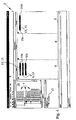
- Fig. 1 shows a partially configured with the configuration device control system, wherein a plurality of I / O access points 3 in a model configuration field 4 several hardware functionalities in a function configuration field 6 and multiple hardware interfaces 7 in an interface configuration field 8 by means of the display device 2 are shown. Due to the configuration of the configuration device according to the invention, I / O access points 3 and hardware functionalities 5 can in principle be assigned to each other, just as hardware functionalities 5 can in turn be assigned to hardware interfaces 7.
- FIG. 1 to 10 illustrated embodiment of the configuration device is characterized in that the I / O access points 3 in the model configuration field 4, the hardware functionalities 5 in the function configuration field 6 and the hardware interfaces 7 in the interface configuration field 8 by blocks 9 with input and / or output ports 10a, 10b are displayed in which the I / O access points 3 and / or the hardware functionalities 5 and / or the hardware interfaces 7 can be assigned to one another by graphic assignment means.
- these graphic allocation means are implemented as signal lines 11.
- I / O access points 3, hardware functionalities 5 and hardware interfaces 7 in the corresponding configuration fields 4, 6, 8 by blocks 9 and the assignment of individual elements of the configuration fields by signal lines 11 between the input and output ports 10a, 10b of the respective blocks 9 greatly simplifies and speeds up the configuration of a control system over known textual techniques.
- the input and output ports 10a, 10b are configured to represent the possible and / or actual signal directions of the I / O access points 3 in the model configuration field 4 and / or the hardware functionalities 5 in the function configuration field 6 and / or the hardware interfaces 7 in the interface configuration field 8 show. This prevents misallocations, which may for example result from input ports 10a being interconnected and output ports 10b being connected together.
- the signal directions are symbolized by input and output ports 10a, 10b, which are configured as arrows pointing either from the respective block 9, away or to the respective block 9.
- the embodiments of the configuration device according to the Fig. 1 to 10 are also distinguished by the fact that the displayed contents 12a, 12b, 12c of the model configuration field 4 and / or the function configuration field 6 and / or the interface configuration field 8 are displaceable relative to one another in such a way that I / O access points 3 assigned to or to be assigned to one another and / or or hardware functionalities 5 and / or hardware interfaces 7 adjacent to each other simultaneously representable and thus can be assigned to each other and / or are configured together.
- hardware functionalities 5 and hardware interfaces 7 are used by the configuration devices according to the Fig. 1 to 10 optionally only the signal lines 11 shown, the visible contents 12 of the configuration fields 4, 6, 8 interconnect, ie that signal lines that start or end outside the configuration fields 4, 6, 8, can be hidden if necessary for the sake of clarity.
- a superordinate unit 13 in an expanded representation 14 (see, for example, all superior units 13 in the Fig. I and 6 ), which may separately represent all of the input and output ports 10a, 10b of the I / O access points 3 or hardware functionalities 5 or hardware interfaces 7 included in the parent unit 13, or alternatively, a parent unit 13 in a reduced representation IS all inputs and output ports 10a, 10b of the I / O access points 3 included in the higher-level unit 13 or hardware functionalities 5 or hardware interfaces 7 by at least one common input port and / or at least one common output port 10c, 10d.
- All in the Fig. 1 to 10 illustrated embodiments of a configuration device are further characterized in that all available I / O access points 3 and / or hardware functionalities 5 and / or hardware interfaces 7 are displayed in a selection box 16 and in a selection box 16 individually or grouped selectable. Selected I / O access points 3 and / or hardware functionalities 5 and / or hardware interfaces 7 can then be transferred from the selection field 16 into the respectively corresponding configuration field 4, 6, 8.
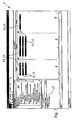
- FIG. 3 illustrates step-by-step how I / O access points 3 or superordinate units 13 with I / O access points 3 are selected from selection field 16 and placed in model configuration field 4.
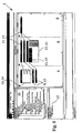
- Fig. 4 is selected from the selection field 16 of the many existing hardware interfaces 7 with the "PS-FPD 2 / I" designated hardware interface 7 and placed in the interface configuration field 8.
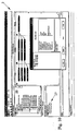
- Fig. 5 such as the hardware functionalities 5 selected with "PVVM out 1,”"ADC mux 1" and "bit out 1" from the selection box 16 and placed in the function configuration field 6.
- the Fig. 1 to 10 This also reflects a variant of the claimed method for generating at least part of an executable control program for controlling a control system, wherein at least one 1 / O access point 3 in a model configuration field 4 and / or at least one hardware functionality 5 in a function configuration field 6 and / or at least one hardware interface 7 is displayed in an interface configuration field 8 and / or at least one displayed I / O access point 3 and at least one displayed hardware functionality 5 are assigned to one another and / or at least one displayed hardware functionality 5 and at least one displayed hardware interface 7 are assigned to one another
- the I / O access points 3 in the model configuration field 4, the hardware functionalities 5 in the function configuration field 6 and the hardware interfaces 7 in the interface configuration field 8 are represented by blocks 9 Input and / or output ports 10a, 10b are shown and subsequently the I / O access points 3 and / or the hardware functionalities 5 and / or the hardware interfaces 7 are assigned to each other by graphic assignment means - in particular by signal lines 11 - and finally using the
Landscapes
- Physics & Mathematics (AREA)
- General Physics & Mathematics (AREA)
- Engineering & Computer Science (AREA)
- Automation & Control Theory (AREA)
- Programmable Controllers (AREA)
- User Interface Of Digital Computer (AREA)
Description
- Die Erfindung betrifft eine Konfigurationseinrichtung zur Konfiguration eines Steuerungssystems mit mindestens einer elektronischen Rechnereinheit und mindestens einem zugeordneten I/O-Gerät, wobei mindestens ein Teil eines mit der Konfiguration korrespondierenden Steuerungsprogramms zur Steuerung des Steuerungssystems erzeugbar ist und wobei die Konfigurationseinrichtung mindestens eine Anzeigevorrichtung aufweist, wobei mindestens ein I/O-Zu-griffspunkt in einem Modellkonfigurationsfeld und mindestens eine Hardwarefunktionalität in einem Funktionskonfigurationsfeld und mindestens eine Hardwareschnittstelle in einem Schnittstellenkonfigurationsfeld mittels der Anzeigevorrichtung darstellbar sind, wobei mindestens ein I/O-Zugriffspunkt und mindestens eine Hardwarefunktionalität einander zuordenbar sind und/oder wobei mindestens eine Hardwarefunktionalität und mindestens eine Hardwareschnittstelle einander zuordenbar sind. Ferner betrifft die Erfindung ein diesbezügliches Computerprogramm.
- Einrichtungen und Verfahren zur Konfiguration von Steuerungssystemen und zur automatischen oder teilautomatisierten Erzeugung von Steuerungsprogrammen für Steuerungssysteme sind aus der Praxis in verschiedener Form bekannt und werden vor allem in der angewandten Forschung und der industriellen Entwicklung in dem weiten Feld der Entwicklung und dem Einsatz elektronischer Steuerungssysteme verwendet, nämlich überall dort, wo im weitesten Sinne Prozeßsteuerungsaufgaben gelöst werden müssen. Der Begriff Steuerungssystem wird im folgenden als umfassende Bezeichnung für eine technische Einrichtung verwendet, die im wesentlichen für die Aufgaben Messen, Steuern, Regeln, Kalibrieren eingesetzt wird; es kann sich dabei im weitesten Sinne um ein elektronisches, programmsteuerbares System handeln. Der Begriff ist nicht auf das beschränkt, was im systemtheoretischen Sinne einengend als Steuerung definiert wird.
- Ein elektronisches Steuerungssystem der hier in Rede stehenden Art besteht aus mindestens einer elektronischen Rechnereinheit, d. h. aus einem Single- bzw. Multiprozessorsystem, das üblicherweise mit einem Echtzeitbetriebssystem betrieben wird. Diese Rechnereinheit ist mit dem zu steuernden Prozeß über entsprechende I/O-Geräte verbunden.
- Unter I/O-Geräten wird im Rahmen der Lehre dieser Erfindung eine große Bandbreite an möglichen technischen Geräten mit einer oder mehreren Außenweltschnittstellen verstanden. Neben den üblichen Geräten mit analogen und digitalen Ein- und Ausgabekanälen zählen dazu unter anderem auch Geräte mit intelligenter Signalverarbeitung zum Pre- und Postprocessing von Daten, Datenbus-Module, Geräte zur Signalkonditionierung, aber zum Beispiel auch Leistungsmodule. Ein I/O-Gerät kann gerätetechnisch eine separate Einheit bilden, die einer Rechnereinheit hinzugefügt werden kann (beispielsweise interner Bussteckplatz in der Rechnereinheit, Ankopplung über eine externe Kommunikationsschnittstelle), es kann aber auch untrennbarer Bestandteil einer Rechnereinheit sein, z. B. wenn in einem Prozessor I/O Gerätefunktionalität integriert umgesetzt wird. Die Lehre der Erfindung ist grundsätzlich auf keine spezielle gerätetechnische Ausführungsform beschränkt oder von einer solchen abhängig.
- Die in einem beliebigen Steuerungssystem hardwaremäßig implementierte und nutzbare Funktionalität wird im folgenden als Hardwarefunktionalität bezeichnet; dies kann beispielsweise ein Digital-Analog- oder ein Analog-Digital-Wandler sein, darunter fallen aber auch komplexe parametrierbare Module, wie z. B. Datenbusse (inklusive der Definition der durch sie übertragbaren Nachrichten und ihres Timingverhaltens), digitale Signalprozessoren (inklusive der Beschreibung zur Generierung / Analyse von Signalverläufen) oder auch Module zur Pulsweiten-Modulation von Signalen.
- Von den beschriebenen Hardwarefunktionalitäten sind im Rahmen der vorliegenden Erfindung zu unterscheiden die Hardwareschnittstellen des Steuerungssystems. Moderne Steuerungssysteme weisen eine flexible Hardwarearchitektur auf, die es gestattet, Signale, die von einem Modul mit einer bestimmten Hardwarefunktionalität stammen, innerhalb des Steuerungssystems über frei wählbare Signalpfade zu leiten (Routen von Signalpfaden). Dies ist insbesondere für Steuerungssysteme interessant, die neben elementaren I/O-Geräten beispielsweise auch I/O-Geräte für die Signalkonditionierung (zum Beispiel Wandlung von Stromsignalen in Spannungssignale, Wandlung von eingangsseitigen Signalen eines bestimmten Bereichs in ausgangsseitige Signale eines anderen Bereichs) und/oder Leistungsmodule (z. B. Ausgabe von hohen elektrischen Strömen oder Spannungen) umfassen. Bei entsprechend flexibler Hardwarearchitektur eines Steuerungssystems läßt sich beispielsweise frei konfigurieren, welcher Kanal eines I/O-Geräts (z. B. eines Digitalen/Analog-Wandlers) auf welchen eingangsseitigen Kanal eines I/O-Geräts zur Ausgabe von Leistungssignalen geführt wird, auf welchen ausgangsseitigen Kanal dieses I/O-Geräts das Leistungssignal ausgegeben wird und über welchen Pin eines Connectors das Signal letztendlich abgegriffen werden kann; sinngemäß wird mit einzulesenden Signalen verfahren. Insbesondere bei der Arbeit mit großen Steuerungssystemen, die z. B. bei Hardware-In-The-Loop-Prüfständen zum Einsatz kommen, bietet diese Eigenschaft erhebliche Vorteile gegenüber einer nicht konfigurierbaren festen Verdrahtung von Steuerungssystemen. Diese Komponenten des Steuerungssystems werden im folgenden als Hardwareschnittstellen des Steuerungssystems bezeichnet.
- Bei der Einrichtung und Konfiguration eines Steuerungssystems sind zwei grundsätzliche Aufgaben zu lösen. In einem ersten Schritt muß im Rahmen der sogenannten Funktionsentwicklung abstrakt, d. h. losgelöst von den Hardware-Eigenschaften des Steuerungssystems, die Funktionalität des Steuerungssystems definiert werden. Darunter ist beispielsweise die mathematische Beschreibung eines auf dem Steuerungssystem zu implementierenden Reglers zu verstehen. Diese Funktionsentwicklung wird üblicherweise durch mathematische Entwurfswerkzeuge unterstützt, die einen blockschaltbild orientierten Entwurf der später auf dem Steuerungssystem zu implementierenden Funktionalität gestattet. Ergebnis der Funktionsentwicklung ist ein mathematisches Modell der geplanten abstrakten Funktionalität des Steuerungssystems, in dem zwar alle notwendigen Eingangs- bzw. Ausgangsgrößen abstrakt bekannt sind, das Modell jedoch keinerlei Bezug zu der Hardwarefunktionalität und den Hardwareschnittsstellen des Steuerungssystems hat. Es ist zwar möglich, mit Hilfe dieses Modells ein Steuerungsprogramm zu erzeugen, das auf dem Steuerungssystem lauffähig ist, jedoch kann ein solches Steuerungsprogramm nicht auf die Hardwarefunktionalität und die Hardwareschnittstellen des Steuerungssystems zugreifen, da in dem abstrakten Modell keine derartigen Informationen zur Konfiguration des Steuerungssystems hinterlegt worden sind.
- In einem zweiten grundsätzlichen Schritt bei der Einrichtung und Konfiguration eines Steuerungssystems muß deshalb ein Zusammenhang hergestellt werden zwischen bestimmten Ein- bzw. Ausgangsgrößen des Modells einerseits und andererseits den Hardwarefunktionalitäten bzw. den Hardwareschnittstellen des Steuerungssystems.
- Zur Bewältigung der aufgezeigten Aufgabe ist aus dem Stand der Technik bekannt, schon in der Modellierungsumgebung zur Modellierung des abstrakten Modells die Schnittstellen zu den I/O-Geräten zu modellieren. Zu diesem Zweck werden dann beispielsweise ergänzende Blockbibliotheken zur Beschreibung der I/O-Geräte bzw. der Hardwarefunktionalitäten des Steuerungssystems benutzt, wobei verschiedene Blöcke unterschiedliche Hardwarefunktionalitäten repräsentieren, deren Eigenschaften in der Modellierungsumgebung bzw. dem Blockdiagramm, z. B. durch Dialogfenster oder ähnliche Mittel einstellbar sind. Durch Hinterlegung von Informationen in dem ursprünglich abstrakten Modell, die die Hardwarefunktionalitäten und Hardwareeigenschaften des Steuerungssystems betreffen, ist es zwar möglich, aus dem ergänzten Modell nunmehr ein Steuerungsprogramm zu generieren, das nicht nur die abstrakte Funktionalität - beispielsweise eines Regelungsalgorithmus - umsetzt, sondern gleichzeitig auch - beispielsweise durch Aufruf geeigneter Treiber - die Hardwarekomponenten des Steuerungssystems in geeigneter Weise aktiviert, jedoch wird dies mit vielerlei Nachteilen bei der Konfigurierbarkeit des Steuerungssystems erkauft.
- Aus der
EP 1 522 910 Al ist ein weiteres Verfahren zur Einrichtung und Konfiguration eines Steuerungssystems bekannt, von dem die vorliegende Erfindung ausgeht. Bei diesem Verfahren wird die Zuordnung von bestimmten Ein- bzw. Ausgangsgrößen des abstrakten Modells zu bestimmten Hardwarefunktionalitäten und Hardwareschnittstellen sowie die Parametrierung und Konfiguration der Hardwarefunktionalitäten und Hardwareschnittstellen nicht mehr in dem abstrakten Modell vorgenommen, sondern geschieht dies separat von dem abstrakten Modell. In dem abstrakten Modell werden lediglich bestimmte Signale als (symbolische) I/O-Zugriffspunkte gekennzeichnet, was lediglich bedeutet, daß es sich hierbei um Signale handelt, die auf dem tatsächlichen Steuerungssystem unter Nutzung einer bestimmten Hardwarefunktionalität als physikalisches Signal ausgegeben bzw. als physikalisches Signal eingelesen werden. Die Zuordnung von den I/O-Zugriffspunkten des Modells zu Hardwarefunktionalitäten und von Hardwarefunktionalitäten zu Hardwareschnittstellen erfolgt hier unabhängig von dem Modell, die Zuordenbarkeit der verschiedenen Komponenten des Steuerungssystems ist aufgrund des textuellen, tabellarischen Verfahrens nur eingeschränkt möglich, gleiches gilt für die Orientierung innerhalb der zur Verfügung stehenden Komponenten des Steuerungssystems bei der Konfigurierung oder auch bei der Erfassung einer existierenden Konfiguration. - Aus der
US 5,168,441 A ist ebenfalls eine textuelle tabellarische Zuordnung bei einer Vorrichtung zur Einrichtung und Programmierung einer Prozeßsteuerung bekannt , wobei hier I/O-Kanäle der Hardware zu Signalnamen aus einem Modell zugeordnet werden; es liegen die gleichen Probleme vor, die vorstehend in Zusammenhang mit tabellarischen Zuordnungsverfahren aufgezeigt worden sind. - Der Erfindung liegt nun die Aufgabe zugrunde, eine Einrichtung und ein Verfahren zur Konfiguration eines Steuerungssystems und zur Erzeugung mindestens eines Teils eines mit der Konfiguration korrespondierenden Steuerungsprogramms anzubieten, bei denen die oben genannten Nachteile - zumindest teilweise - vermieden werden.
- Die zuvor aufgezeigte Aufgabe ist erfindungsgemäß zunächst bei einer Konfigurationseinrichtung der in Rede stehenden Art zur Konfiguration eines Steuerungssystems mit mindestens einer elektronischen Rechnereinheit und wenigstens einem zugeordneten I/O-Gerät gelöst durch die Merkmale des Kennzeichnungsteils von Patentanspruch 1.
- Die erfindungsgemäße Konfigurationseinrichtung ist gegenüber dem Stand der Technik in vielerlei Hinsicht vorteilhaft. Dadurch, daß die Elemente der verschiedenen Konfigurationsfelder durch Blöcke mit Eingangs- und/oder Ausgangsports dargestellt werden, sind technische und funktionale Einheiten innerhalb der Konfigurationsfelder (Modellkonfigurationsfeld, Funktionskonfigurationsfeld und Schnittstellenkonfigurationsfeld) darstellbar, die auch in der Konfigurationsumgebung hardwaremäßige und logische Funktionseinheiten des zu konfigurierenden Steuerungssystems widerspiegeln. Anders als bei einer rein tabellenartigen Repräsentation separater Kanäle einer Hardwareeinheit - wie z. B. die Kanäle eines A/D-Wandlers - ist die blockorientierte Darstellung von Elementen eines Konfigurationsfeldes in sinnfälliger Weise strukturierbar und unterstützt damit mit technischen Mitteln die Konfigurierbarkeit eines Steuerungssystems ganz erheblich. Die erfindungsgemäße Konfigurationseinrichtung weist gegenüber dem Stand der Technik den weiteren Vorteil auf, daß Elemente der verschiedenen Konfigurationsfelder, also I/O-Zugriffspunkte des Modellkonfigurationsfeldes, Hardwarefunktionalitäten des Funktionskonfigurationsfeldes bzw. Hardwareschnittstellen des Schnittstellenkonfigurationsfeldes in der blockorientierten Darstellung durch graphische Zuordnungsmittel zuordenbar sind, wodurch bei der Konfiguration in sinnfälliger Weise sofort erkennbar ist, welche Elemente der Konfigurationsfelder noch nicht im Rahmen der Konfiguration verwendet worden sind und daher noch weiter bei der Einrichtung und Konfiguration des Steuerungssystems frei zur Verfügung stehen. Darüber hinaus ist unmittelbar erkennbar, welche Zuordnungen zwischen den Elementen verschiedener Konfigurationsfelder bereits vorgenommen worden sind, wobei auch mehrere Zuordnungen gleichzeitig in eindeutiger Weise, unmißverständlich darstellbar und erkennbar sind.
- Vorteilhaft, jedoch nicht Gegenstand der Erfindung, sind mit den Eingangs- und Ausgangsports die möglichen und/oder die tatsächlichen Signalrichtungen der I/O-Zugriffspunkte im Modellkonfigurationsfeld und/oder der Hardwarefunktionalitäten im Funktionskonfigurationsfeld und/oder der Hardwareschnittstellen im Schnittstellenkonfigurationsfeld anzeigbar. Diese Ausgestaltung der Konfigurationseinrichtung ermöglicht automatisch eine Verfolgung der Signalflüsse innerhalb des konfigurierten Steuerungssystems mit der Konfigurationseinrichtung, was wiederum mit den aus dem Stand der Technik bekannten tabellenartigen Zuordnungen nicht möglich ist. Gleichzeitig hilft diese Maßnahme, Fehlzuordnungen zwischen I/O-Zugriffspunkten, Hardwarefunktionalitäten und Hardwareschnittstellen zu vermeiden, da der Ein- bzw. Ausgangscharakter der entsprechenden Ports der Blöcke erkennbar ist und so beispielsweise die falsche Zuordnung von Ausgängen zu Ausgängen bzw. von Eingängen zu Eingängen offensichtlich und automatisch durch die Konfigurationseinrichtung erkennbar wird.
- Erfindungsgemäß sind die dargestellten Inhalte des Modellkonfigurationsfeldes und/oder des Funktionskonfigurationsfeldes und/oder des Schnittstellenkonfigurationsfeldes so relativ zueinander verschiebbar, daß einander zugeordnete oder zuzuordnende I/O-Zugriffspunkte und/oder Hardwarefunktionalitäten und/oder Hardwareschnittstellen benachbart zueinander gleichzeitig darstellbar und damit einander zuordenbar sind und/oder gemeinsam konfigurierbar sind.
- Die relative Verschiebbarkeit der Inhalte kann sich beispielsweise in einer Bewegungsrichtung erschöpfen, wenn die Inhalte der Konfigurationsfelder zeilen- oder spaltenartig angeordnet sind. Durch die Verschiebbarkeit der Inhalte zweier Konfigurationsfelder können beliebige Teilinhalte der verschiedenen Konfigurationsfelder in unmittelbare Nachbarschaft zueinander gebracht werden, so daß sie durch graphische Zuordnungsmittel einander zuordenbar sind, vorliegend und erfindungsgemäß also durch Signallinien miteinander verbunden werden können. Dabei können erfindungsgemäß einmal durch Signallinien vorgenommene Zuordnungen zwischen Elementen verschiedener Konfigurationsfelder auch bei der Relativbewegung von Inhalten dieser Felder beibehalten werden, indem die Signallinien der Relativbewegung elastisch folgen. Durch die benachbarte Darstellung der Inhalte von verschiedenen Konfigurationsfeldern wird auch gewährleistet, daß Konfigurationen von I/O-Zugriffspunkten, Hardwarefunktionalitäten und Hardwareschnittstellen aufeinander abstimmbar sind, da diese gleichzeitig eingesehen und miteinander abgeglichen werden können.
- In einem bevorzugten Ausführungsbeispiel ist die erfindungsgemäße Konfigurationseinrichtung derart ausgestaltet, daß zu mindestens einem ausgewählten I/O-Zugriffspunkt im Modellkonfigurationsfeld oder zu mindestens einer Hardwarefunktionalität im Funktionskonfigurationsfeld oder zu mindestens einer Hardwareschnittstelle im Schnittstellenkonfigurationsfeld die zugeordneten und/oder zuordenbaren I/O-Zugriffspunkte und/oder Hardwarefunktionalitäten und/oder Hardwareschnittstellen automatisch erkennbar und mit der Anzeigevorrichtung selektiv darstellbar sind. Das bedeutet, daß die Konfigurationseinrichtung bei Auswahl eines Elements eines Konfigurationsfeldes automatisch in den anderen Konfigurationsfeldern die mit dem ausgewählten Element verbundenen Elemente der anderen Konfigurationsfelder zur Darstellung bringt. Dies kann durch Verschieben der Inhalte der anderen Konfigurationsfelder geschehen oder aber auch durch Umordnung der Elemente innerhalb der anderen Konfigurationsfelder. Mit dieser Funktionalität ist es auch möglich, zu dem ausgewählten Element eines Konfigurationsfeldes innerhalb der anderen Konfigurationsfelder nur die dem ausgewählten Element potentiell zuordenbaren Elemente anzuzeigen, indem beispielsweise zu einem als Ausgang gekennzeichneten I/O-Zugriffspunkt nur solche Hardwarefunktionalitäten und Hardwareschnittstellen angezeigt werden, die ihrerseits eine Ausgangsfunktionalität aufweisen, die also tatsächlich ein Ausgangssignal generieren können.
- Die Konfigurationseinrichtung unterstützt den Konfigurationsvorgang ferner dadurch, daß formale Fehler bei der Konfiguration erkannt und angezeigt werden, beispielsweise dann, wenn Eingangsports bzw. Ausgangsports von - verschiedenen - Blöcken jeweils untereinander verbunden werden, ohne daß das Verbindungsmittel mit einem komplementären Ausgangsport bzw. Eingangsport verbunden ist.
- Erfindungsgemäß sind mehrere I/O-Zugriffspunkte im Modellkonfigurationsfeld und/oder mehrere Hardwarefunktionalitäten im Funktionskonfigurationsfeld und/oder mehrere Hardwareschnittstellen im Schnittstellenkonfigurationsfeld jeweils zu einer übergeordneten Einheit zusammenfaßbar, insbesondere zu einem übergeordneten Block. Dies hat den Vorteil, daß beispielsweise alle zur Umsetzung einer bestimmten Funktionalität - z. B. Lambda-Sonde - notwendigen Hardwarefunktionalitäten gruppierbar sind und damit innerhalb eines Konfigurationsfeldes nicht mehr zergliedert und ihrem Sinnzusammenhang entrissen werden können.
- In einer weiteren bevorzugten Ausgestaltung der Erfindung sind alle verfügbaren I/O-Zugriffspunkte und/oder Hardwarefunktionalitäten und/oder Hardwareschnittstellen in einem Auswahlfeld darstellbar und einzeln aus wählbar, wobei ausgewählte I/O-Zugriffspunkte und/oder Hardwarefünktionalitäten und/oder Hardwareschnittstellen von dem Auswahlfeld in das jeweils korrespondierende Konfigurationsfeld (Modellkonfigurationsfeld, Funktionskonfigurationsfeld, Schnittstellenkonfigurationsfeld) übertragbar sind. Dabei ist es durchaus beabsichtigt, daß nur eine Auswahl i. S. einer Teilmenge der verfügbaren I/O-Zugriffspunkte und/oder Hardwarefünktionalitäten und/oder Hardwareschnittstellen in dem korrespondierenden Konfigurationsfeld angeordnet werden können, um lediglich einen überschaubaren Aspekt des Steuerungssystems zu konfigurieren, um beispielsweise nur diejenigen Resourcen des Steuerungssystems zu konfigurieren, die zur Erledigung der jeweils vorliegenden Aufgabenstellung erforderlich sind.
- Wie auch bei aus dem Stand der Technik bekannten Konfigurationseinrichtungen verfügt auch die erfindungsgemäße Konfigurationseinrichtung zwangsläufig über Schnittstellen, über die die Konfigurationseinrichtung Informationen über die verfügbaren I/O-Zugriffspunkte, Hardwarefunktionalitäten und Hardwareschnittstellen erhält. Dabei kann es sich lediglich um eine Datei- bzw. Datenbankschnittstelle handeln, genauso gut kann es sich aber auch um eine Schnittstelle zu einer vorhandenen Modellierungseinrichtung und/oder zu einem real vorhandenen Steuerungssystem handeln, über die die Konfigurationseinrichtung das mit der Modellierungseinrichtung erstellte Modell mit seinen I/O-Zugriffspunkten bzw. die Hardwarefunktionalitäten und die Hardwareschnittstellen des angeschlossenen Steuerungssystems automatisch erkennt und der Konfiguration zugänglich macht.
- Die Gesamtheit der verfügbaren Informationen ist dann in dem Auswahlfeld darstellbar, wobei eine Auswahl von I/O-Zugriffspunkten, Hardwarefunktionalitäten und Hardwareschnittstellen aus dem Auswahlfeld in das korrespondierende Konfigurationsfeld übertragen werden können. Dies ist beispielsweise dann sinnvoll, wenn mit der Konfigurationsumgebung z. B. nur ein beschränkter Aspekt des Steuerungssystems konfiguriert werden soll und auf die Darstellung aller Elemente innerhalb der Konfigurationsfelder aus Gründen der Übersichtlichkeit bewußt verzichtet wird.
- In diesem Zusammenhang ist eine bevorzugte Ausgestaltung der Konfigurationseinrichtung dadurch gekennzeichnet, daß mindestens eine Auswahl von I/O-Zugriffspunkten und/oder von Hardwarefunktionalitäten und/oder von Hardwareschnittstellen in mindestens einer Arbeitsansicht zusammenfaßbar sind, wobei besonders bevorzugt nicht in der Auswahl enthaltene I/O-Zugriffspunkte, Hardwarefunktionalitäten und Hardwareschnittstellen nicht angezeigt werden und nicht konfigurierbar sind. Es ist demzufolge möglich, verschiedene Ausschnitte bzw. Elemente ein und desselben Steuerungssystems in verschiedenen, voneinander unabhängigen Arbeitsansichten darzustellen und zu konfigurieren; dies unterstützt und vereinfacht die arbeitsteilige Konfiguration eines Steuerungssystems erheblich. Das bedeutet mit anderen Worten, daß die verschiedenen Auswahlen von I/O-Zugriffspunkten und/oder von Hardwarefunktionalitäten und/oder von Hardwareschnittstellen verschiedener Arbeitsansichten Schnittmengen aufweisen können.
- Hinsichtlich des Aspekts der Arbeitsansichten ist eine bevorzugte Konfigurationseinrichtung so ausgestaltet, daß mehrere Arbeitsansichten zu einer einzigen Arbeitsansicht zusammenführbar sind, wobei mehrfach vorhandene identische I/O-Zugriffspunkte und/oder Hardwarefunktionalitäten und/oder Hardwareschnittstellen aus der einzigen Arbeitsansicht eliminiert werden, so daß keinerlei Redundanzen mehr in der einzigen Arbeitsansicht auftreten. Bevorzugt sind die aus verschiedenen Arbeitsansichten stammenden I/O-Zugriffspunkte und/oder Hardwarefunktionalitäten und/oder Hardwareschnittstellen voneinander unterscheidbar darstellbar, beispielsweise indem sie farblich unterschiedlich dargestellt sind.
- Nach einer weiteren Lehre der Erfindung ist die oben aufgezeigte Aufgabe ferner mit einem Verfahren zur Erzeugung mindestens eines Teils eines ausführbaren Steuerungsprogramms zur Steuerung eines Steuerungssystems mit mindestens einer elektronischen Rechnereinheit und mindestens einem zugeordneten I/O-Gerät dadurch gelöst, daß die I/O-Zugriffspunkte im Modellkonfigurationsfeld, die Hardwarefunktionalitäten im Funktionskonfigurationsfeld und die Hardwareschnittstellen im Schnittstellenkonfigurationsfeld durch Blöcke mit Eingangs- und/oder Ausgangsports dargestellt werden, daß I/O-Zugriffspunkte und/oder Hardwarefunktionalitäten und/oder Hardwareschnittstellen einander durch graphische Zuordnungsmittel - insbesondere durch Signallinien - zugeordnet werden und daß unter Verwendung der in den vorherigen Verfahrensschritten gewonnenen Konfigurationsdaten das Steuerungsprogramm oder ein Teil des Steuerungsprogramms zur Steuerung eines Steuerungssystems automatisch generiert wird.
- In einer besonders vorteilhaften Ausgestaltung des erfindungsgemäßen Verfahrens werden die angezeigten Inhalte des Modellkonfigurationsfeldes und/ oder des Funktionskonfigurationsfeldes und/oder des Schnittstellenkonfigurationsfeldes so relativ zueinander verschoben, daß einander zugeordnete oder zuzuordnende I/O-Zugriffspunkte und/oder Hardwarefunktionalitäten und/ oder Hardwareschnittstellen benachbart zueinander gleichzeitig angezeigt werden und nachfolgend einander zugeordnet und/oder gemeinsam konfiguriert werden.
- Im einzelnen gibt es nun eine Vielzahl von Möglichkeiten, die erfindungsgemäße Konfigurationseinrichtung zur Konfiguration eines Steuerungssystems bzw. das erfindungsgemäße Verfahren auszugestalten und weiterzubilden. Dazu wird verwiesen sowohl auf die den Patentansprüchen 1 und 10 nachgeordneten Patentansprüche als auch auf die Beschreibung eines in der Zeichnung dargestellten Ausführungsbeispiels der erfindungsgemäßen Konfigurationseinrichtung bzw. des erfindungsgemäßen Verfahrens zur Konfiguration eines Steuerungssystems. In der Zeichnung zeigen
- Fig. 1
- die Konfiguration eines Steuerungssystems mit einem bevorzugten Ausführungsbeispiel der erfmdungsgemäßen Konfigurationseinrichtung,
- Fig. 2
- das Anfangsstadium der Konfiguration eines Steuerungssystems mit der erfindungsgemäßen Konfigurationseinrichtung,
- Fig. 3
- eine weiter fortgeschrittene Konfiguration eines Steuerungssystems mit dem bevorzugten Ausführungsbeispiel einer erfindungsgemäßen Konfigurationseinrichtung,
- Fig. 4
- eine noch weiter fortgeschrittene Konfiguration eines Steuerungssystems mit dem bevorzugten Ausführungsbeispiel einer erfindungsgemäßen Konfigurationseinrichtung,
- Fig. 5
- eine noch weiter fortgeschrittene Konfiguration eines Steuerungssystems mit dem bevorzugten Ausführungsbeispiel einer erfindungsgemäßen Konfigurationseinrichtung,
- Fig. 6
- die Konfiguration nach
Fig. 5 mit expandierter Blockdarstellung, - Fig. 7
- die Konfiguration nach
Fig. 1 mit reduzierter Blockdarstellung, - Fig. 8
- die Konfiguration nach den
Fig. 1 und7 in gemischt reduzierter und expandierter Blockdarstellung, - Fig. 9
- eine weitere Konfiguration eines Steuerungssystems nach einem bevorzugten Ausführungsbeispiel der erfindungsgemäßen Konfigurationseinrichtung und
- Fig. 10
- ein letztes Beispiel für die Konfiguration eines Steuerungssystems mit der erfindungsgemäßen Konfigurationseinrichtung bzw. mit dem erfindungsgemäßen Verfahren.
- Die
Fig. I bis 10 zeigen jeweils bevorzugte Ausführungsbeispiele eines erfindungsgemäßen Konfigurationssystems 1 bzw. den über eine Anzeigevorrichtung 2 wahrnehmbaren Teil der Konfigurationseinrichtung 1; ebenso ist anhand derFig. I bis 10 die Durchführung des erfindungsgemäßen Verfahrens zur Konfiguration eines Steuerungssystems ersichtlich. - Steuerungssysteme, auf die hier im folgenden Bezug genommen wird, bestehen aus einer elektronischen Rechnereinheit und mindestens einem zugeordneten I/O-Gerät, wobei weder die Rechnereinheit noch das zugeordnete I/0-Gerät im folgenden bildlich dargestellt sind. Abschließendes Ziel der Konfiguration ist es, mit Hilfe der vorgenommenen Konfiguration des Steuerungssystems ein Steuerungsprogramm zu erzeugen, mit dessen Hilfe das Steuerungssystem gesteuert werden kann. Dabei kann es auch sein, daß die Konfigurationseinrichtung nur den Teil des Steuerungsprogramms zur Steuerung des Steuerungssystems erzeugt, der auf der mit der Konfigurationseinrichtung vorgenommenen Konfiguration des Steuerungssystems beruht. Dieser Teil des Steuerungsprogramms muß auf dem Steuerungssystem nicht selbständig lauffähig sein, vielmehr kann es sich hierbei auch nur um eine Bibliothek von Funktionen handeln, die aus einem anderen Programm heraus zur hardwaremäßigen Ansteuerung des Steuerungssystems aufgerufen wird. Die Konfigurationseinrichtung ist grundsätzlich auch nicht beschränkt auf irgendeine spezielle softwaretechnische Umsetzung des erzeugten Steuerungsprogramms bzw. eines Teils eines Steuerungsprogramms. Hierbei kann es sich beispielsweise um einen fertig kompilierten - und damit unmittelbar auf dem eingesetzten Steuerungssystem lauffähigen - Code handeln, es kann sich dabei aber genauso gut um beispielsweise einen Bytecode handeln, der erst über eine virtuelle Maschine, die auf dem Steuerungssystem implementiert ist, interpretiert werden muß, um dann ausgeführt zu werden.
-
Fig. 1 zeigt ein mit der Konfigurationseinrichtung teilweise fertig konfiguriertes Steuerungssystem, wobei mehrere I/O-Zugriffspunkte 3 in einem Modellkonfigurationsfeld 4 mehrere Hardwarefunktionalitäten in einem Funktionskonfigurationsfeld 6 und mehrere Hardwareschnittstellen 7 in einem Schnittstellenkonfigurationsfeld 8 mittels der Anzeigevorrichtung 2 dargestellt werden. Durch die erfindungsgemäße Ausgestaltung der Konfigurationseinrichtung sind I/O-Zugriffspunkte 3 und Hardwarefunktionalitäten 5 grundsätzlich einander zuordenbar, genauso wie Hardwarefunktionalitäten 5 wiederum Hardwareschnittstellen 7 zuordenbar sind. - Das in den
Fig. 1 bis 10 dargestellte Ausführungsbeispiel der erfindungsgemäßen Konfigurationseinrichtung zeichnet sich dadurch aus, daß die I/O-Zugriffspunkte 3 im Modellkonfigurationsfeld 4, die Hardwarefunktionalitäten 5 im Funktionskonfigurationsfeld 6 und die Hardwareschnittstellen 7 im Schnittstellenkonfigurationsfeld 8 durch Blöcke 9 mit Eingangs- und/oder Ausgangsports 10a, 10b darstellbar sind, wobei die I/O-Zugriffspunkte 3 und/oder die Hardwarefunktionalitäten 5 und/ oder die Hardwareschnittstellen 7 einander durch graphische Zuordnungsmittel zuordenbar sind. In allen in denFig. 1 bis 10 dargestellten Ausführungsbeispielen sind diese graphischen Zuordnungsmittel als Signallinien 11 implementiert.
Die Repräsentation von I/O-Zugriffspunkten 3, Hardwarefunktionalitäten 5 und Hardwareschnittstellen 7 in den korrespondierenden Konfigurationsfeldern 4, 6, 8 durch Blöcke 9 und die Zuordnung einzelner Elemente der Konfigurationsfelder durch Signallinien 11 zwischen den Eingangs- bzw. Ausgangsports 10a, 10b der entsprechenden Blöcke 9 vereinfacht und beschleunigt die Konfiguration eines Steuerungssystems gegenüber den bekannten textuellen Techniken erheblich. - Besonders vorteilhaft ist es, wenn, wie in den
Fig. 1 ,6 ,8 und9 dargestellt, die Eingangs- und Ausgangsports 10a, 10b so ausgestaltet sind, daß sie die möglichen und/oder tatsächlichen Signalrichtungen der I/O-Zugriffspunkte 3 im Modellkonfigurationsfeld 4 und/oder der Hardwarefunktionalitäten 5 im Funktionskonfigurationsfeld 6 und/oder der Hardwareschnittstellen 7 im Schnittstellenkonfigurationsfeld 8 anzeigen. Dadurch wird Fehlzuordnungen vorgebeugt, die beispielsweise daraus resultieren können, daß Eingangsports 10a miteinander verbunden werden bzw. Ausgangsports 10b miteinander verbunden werden. Bei den Blöcken 9 in denFig. 1 ,6 ,8 und9 , werden die Signalrichtungen durch Eingangs- und Ausgangsports 10a, 10b symbolisiert, welche als Pfeile ausgestaltet sind, die entweder von dem jeweiligen Block 9, weg- oder zu dem jeweiligen Block 9 hinzeigen. - Die Ausführungsbeispiele der Konfigurationseinrichtung gemäß den
Fig. 1 bis 10 zeichnen sich darüber hinaus dadurch aus, daß die dargestellten Inhalte 12a, 12b, 12c des Modellkonfigurationsfeldes 4 und/oder des Funktionskonfigurationsfeldes 6 und/oder des Schnittstellenkonfigurationsfeldes 8 so relativ zueinander verschiebbar sind, daß einander zugeordnete oder zuzuordnende I/O-Zugriffspunkte 3 und/oder Hardwarefunktionalitäten 5 und/oder Hardwareschnittstellen 7 benachbart zueinander gleichzeitig darstellbar und damit einander zuordenbar sind und/oder gemeinsam konfigurierbar sind. - Anhand der
Fig. 1 bis 10 ist ersichtlich, daß die Inhalte 12a, 12b, 12c sowohl des Modellkonfigurationsfeldes 4 als auch des Funktionskonfigurationsfeldes 6 sowie des Schnittstellenkonfigurationsfeldes 8 spaltenartig nebeneinander angeordnet sind. Da die Konfigurationsfelder 4, 6, 8 nur eine begrenzte Ausdehnung haben, lassen sich naturgemäß nicht alle Inhalte 12a, 12b, 12c dieser Felder gleichzeitig darstellen. Die Übersichtlichkeit bei der Zuordnung von Elementen der Konfigurationsfelder 4, 6, 8 wird dadurch gewährleistet, daß die Inhalte 12a, 12b, 12c der Konfigurationsfelder 4, 6, 8 in vertikaler Richtung so gegeneinander bewegt werden können, daß die einander zuzuordnenden Elemente nebeneinander zu liegen kommen und damit verbindbar bzw. gemeinsam konfigurierbar sind. - Bei einer großen Anzahl von I/O-Zugriffspunkten 3, Hardwarefunktionalitäten 5 und Hardwareschnittstellen 7 werden durch die Konfigurationseinrichtungen gemäß den
Fig. 1 bis 10 wahlweise nur die Signallinien 11 dargestellt, die sichtbare Inhalte 12 der Konfigurationsfelder 4, 6, 8 miteinander verbinden, d. h. daß Signallinien, die außerhalb der Konfigurationsfelder 4, 6, 8 beginnen oder enden, bei Bedarf zur Wahrung der Übersichtlichkeit ausgeblendet werden können. - In den
Fig. 1 ,6 ,7 und8 ist zu erkennen, daß es mit den dargestellten Konfigurationseinrichtungen möglich ist, mehrere I/O-Zugriffspunkte 3 im Modellkonfigurationsfeld 4 oder mehrere Hardwarefunktionalitäten 5 im Funktionskonfigurationsfeld 6 und/oder mehrere Hardwareschnittstellen 7 im Schnittstellenkonfigurationsfeld 8 jeweils zu einer übergeordneten Einheit 13 zusammenzufassen. In allen dargestellten Fällen werden die überordneten Einheiten 13 durch einen übergeordneten Block repräsentiert. Aufgrund dieser Eigenschaft ist es beispielsweise möglich, alle Hardwarefunktionalitäten 5, die hardwaremäßig oder funktional zusammenhängen, in einer übergeordneten Einheit 13 zusammenzufassen. In denFig. 1 ,6 und8 gibt es in dem Modellkonfigurationsfeld 4 beispielsweise die übergeordnete Einheit 13 "Phasenansteuerung" und in dem Funktionskonfigurationsfeld 6 die übergeordneten Einheiten 13 'PWM out 1' und "ADC Mux 1", und das Schnittstellenkonfigurationsfeld 8 weist als übergeordnete Einheit 13 den mit 'PS-FBD 2/1" bezeichneten Block auf. - Es hat sich bei den in den
Fig. 1 bis 10 dargestellten Ausführungsbeispielen einer Konfigurationseinrichtung als besonders vorteilhaft herausgestellt, wenn erfindungsgemäß eine übergeordnete Einheit 13 in einer expandierten Darstellung 14 (siehe z. B. alle überordneten Einheiten 13 in denFig. I und6 ) angezeigt wird, die alle Eingangs- und Ausgangsports 10a, 10b der von der übergeordneten Einheit 13 umfaßten I/O-Zugriffspunkte 3 oder Hardwarefunktionalitäten 5 oder Hardwareschnittstellen 7 separat darstellen kann, oder wenn alternativ eine übergeordnete Einheit 13 in einer reduzierten Darstellung IS alle Eingangs- und Ausgangsports 10a, 10b der von der übergeordneten Einheit 13 umfaßten I/O-Zugriffspunkte 3 oder Hardwarefunktionalitäten 5 oder Hardwareschnittstellen 7 durch wenigstens einen gemeinsamen Eingangs- und/oder wenigstens einen gemeinsamen Ausgangsport 10c, 10d darstellt. - Rein reduzierte Darstellungen 15 von übergeordneten Einheiten 13 zeigen die
Fig. 3 bis 5 und7 und die gemischte Darstellung von übergeordneten Einheiten 13, teilweise in expandierter Darstellung 14, teilweise in reduzierter Darstellung 15, zeigtFig. 8 . AusFig. 8 ist weiterhin ersichtlich, daß übergeordnete Einheiten 13 bei dem dargestellten Ausführungsbeispiel der erfindungsgemäßen Konfigurationseinrichtung auch ineinander schachtelbar sind. Hierzu wird verwiesen auf die übergeordnete Einheit 13, die mit "ADC Mux 1' bezeichnet ist und die die weitere übergeordnete Einheit 13 "signal read" beinhaltet, die unabhängig von der expandierten oder reduzierten Darstellung der übergeordneten Einheit 13 "ADC Mux I" ebenfalls expandiert oder reduziert darstellbar ist. - Alle in den
Fig. 1 bis 10 dargestellten Ausführungsbeispiele einer Konfigurationseinrichtung zeichnen sich ferner dadurch aus, daß alle verfügbaren I/O-Zugriffspunkte 3 und/oder Hardwarefunktionalitäten 5 und/oder Hardwareschnittstellen 7 in einem Auswahlfeld 16 dargestellt werden und in einem Auswahlfeld 16 einzeln oder gruppiert auswählbar sind. Ausgewählte I/O-Zugriffspunkte 3 und/oder Hardwarefunktionalitäten 5 und/oder Hardwareschnittstellen 7 können dann von dem Auswahlfeld 16 in das jeweils korrespondierende Konfigurationsfeld 4, 6, 8 übertragen werden. - In den
Fig. 2 bis 5 ist schrittweise dargestellt, wie aus dem Auswahlfeld 16 zunächst I/O-Zugriffspunkte 3 bzw. übergeordnete Einheiten 13 mit I/O-Zugriffspunkten 3 ausgewählt und in dem Modellkonfigurationsfeld 4 plaziert werden. InFig. 4 wird aus dem Auswahlfeld 16 aus den vielen vorhandenen Hardwareschnittstellen 7 die mit "PS-FPD 2/I" bezeichnete Hardwareschnittstelle 7 ausgewählt und in dem Schnittstellenkonfigurationsfeld 8 plaziert. Entsprechend ist inFig. 5 gezeigt, wie die Hardwarefünktionalitäten 5, die mit "PVVM out 1, "ADC Mux 1' und "Bit out 1" aus dem Auswahlfeld 16 ausgewählt und in dem Funktionskonfigurationsfeld 6 plaziert worden sind. - Bei den in den
Fig. 1 bis 10 dargestellten Ausführungsbeispielen von Konfigurationseinrichtungen ist jeweils eine Auswahl von I/O-Zugriffspunkten 3 und/oder von Hardwarefunktionalitäten 5 und/oder von Hardwareschnittstellen 7 in einer Arbeitsansicht 17 zusammengefaßt worden. Es ist möglich, mehrere, sich teilweise inhaltlich überschneidende Auswahlen von I/O-Zugriffspunkten 3 und/oder Hardwarefunktionalitäten 5 und/oder Hardwareschnittstellen 7 in unterschiedlichen Arbeitsansichten 17 zusammenzufassen, so daß verschiedene Aspekte des zu konfigurierenden Steuerungssystem gezielt bearbeitet werden können, ohne daß nicht relevante I/OZugriffspunkte 3 oder Hardwarefunktionalitäten 5 oder Hardwareschnittstellen 7 von der eigentlichen Aufgabe ablenken. - Die
Fig. 1 bis 10 spiegeln damit auch eine Variante des erfindungsgemäß beanspruchten Verfahrens zur Erzeugung mindestens eines Teils eines ausführbaren Steuerungsprogramms zur Steuerung eines Steuerungssystems wider, wobei mindestens ein 1/O-Zugriffspunkt 3 in einem Modellkonfigurationsfeld 4 und/oder mindestens eine Hardwarefunktionalität 5 in einem Funktionskonfigurationsfeld 6 und/oder mindestens eine Hardwareschnittstelle 7 in einem Schnittstellenkonfigurationsfeld 8 angezeigt wird bzw. werden und/oder mindestens ein angezeigter I/O-Zugriffspunkt 3 und mindestens eine angezeigte Hardwarefunktionalität 5 einander zugeordnet werden und/oder mindestens eine angezeigte Hardwarefunktionalität 5 und mindestens eine angezeigte Hardwareschnittstelle 7 einander zugeordnet werden, wobei ferner die I/O-Zugriffspunkte 3 im Modellkonfigurationsfeld 4, die Hardwarefunktionalitäten 5 im Funktionskonfigurationsfeld 6 und die Hardwareschnittstellen 7 im Schnittstellenkonfigurationsfeld 8 durch Blöcke 9 mit Eingangs- und/oder Ausgangsports 10a, 10b dargestellt werden und nachfolgend die I/O-Zugriffspunkte 3 und/oder die Hardwarefunktionalitäten 5 und/oder die Hardwareschnittstellen 7 einander durch graphische Zuordnungsmittel - insbesondere durch Signallinien 11 - zugeordnet werden und wobei letztlich unter Verwendung der in den vorigen Verfahrensschritten gewonnen Konfigurationsdaten das Steuerungsprogramm oder ein Teil des Steuerungsprogramms zur Steuerung eines Steuerungssystems automatisch generiert wird. Dies ergibt sich insbesondere aus den in denFig. 2 bis 5 dargestellten Verfahrensschritten.
Claims (6)
- Konfigurationseinrichtung (1) zur Konfiguration eines Steuerungssystems mit mindestens einer elektronischen Rechnereinheit und mindestens einem zugeordneten I/O-Gerät, wobei mindestens ein Teil eines mit der Konfiguration korrespondierenden Steuerungsprogramms zur Steuerung des Steuerungssystems erzeugbar ist und wobei die Konfigurationseinrichtung mindestens eine Anzeigevorrichtung (2) aufweist, wobei mindestens ein I/O-Zugriffspunkt (3) in einem Modellkonfigurationsfeld (4) und mindestens eine Hardwarefunktionalität (5) in einem Funktionskonfigurationsfeld (6) und mindestens eine Hardwareschnittstelle (7) in einem Schnittstellenkonfigurationsfeld (8) mittels der Anzeigevorrichtung (2) darstellbar sind, wobei mindestens ein I/O-Zugriffspunkt und mindestens eine Hardwarefunktionalität (5) einander zuordenbar sind und/oder wobei mindestens eine Hardwarefunktionalität (5) und mindestens eine Hardwareschnittstelle (7) einander zuordenbar sind,
dadurch gekennzeichnet,
daß die I/O-Zugriffspunkte (3) im Modellkonfigurationsfeld (4), die Hardwarefunktionalitäten (5) im Funktionskonfigurationsfeld (6) und die Hardwareschnittstellen (7) im Schnittstellenkonfigurationsfeld (8) durch Blöcke (9) mit Eingangs- und/oder Ausgangsports (10a, 10b) darstellbar sind, wobei die I/O-Zugriffspunkte (3) und/oder die Hardwarefunktionalitäten (5) und/oder die Hardwareschnittstellen (7) einander durch Signallinien (11) - zugeordnet werden,
daß mehrere I/O-Zugriffspunkte (3) im Modellkonfigurationsfeld (4) und/oder mehrere Hardwarefunktionalitäten (5) im Funktionskonfigurationsfeld (6) und/oder mehrere Hardwareschnittstellen (7) im Schnittstellenkonfigurationsfeld (8) jeweils zu einer übergeordneten Einheit (13) zusammenfassbar sind und
daß eine übergeordnete Einheit (13) in einer expandierten Darstellung (14) alle Eingangs- und Ausgangsports (10a, 10b) der von der übergeordneten Einheit (13) umfassten I/O-Zugriffspunkte (3) oder Hardwarefunktionalitäten (5) oder Hardwareschnittstellen (7) separat darstellt und/oder daß eine überordnete Einheit (13) in einer reduzierten Darstellung (15) alle Eingangs- und Ausgangsports (10a, 10b) der von der übergeordneten Einheit (13) umfassten I/O-Zugriffspunkte (3) oder Hardwarefunktionalitäten (5) oder Hardwareschnittstellen (7) durch wenigstens einen gemeinsamen Eingangs- und wenigstens einen gemeinsamen Ausgangsport (10c, 10d) darstellt und daß die dargestellten Inhalte (12a, 12b, 12c) des Modellkonfigurationsfeldes (4) und/oder des Funktionskonfigurationsfeldes (6) und/oder des Schnittstellenkonfigurationsfeldes (8) so relativ zueinander verschiebbar sind, daß einander zugeordnete oder zuzuordnende I/O-Zugriffspunkte (3) und/oder Hardwarefunktionalitäten (5) und/oder Hardwareschnittstellen (7) benachbart zueinander gleichzeitig darstellbar und damit einander zuordenbar sind und gemeinsam konfigurierbar sind
und daß einmal durch Signallinien vorgenommene Zuordnungen zwischen Elementen verschiedener Konfigurationsfelder auch bei der Relativbewegung von Inhalten dieser Felder beibehalten werden, indem die Signallinien der Relativbewegung elastisch folgen. - Konfigurationseinrichtung nach Anspruch 1, dadurch kennzeichnet, daß zu mindestens einem ausgewählten I/O-Zugriffspunkt (3) im Modellkonfigurationsfeld (4) oder zu mindestens einer Hardwarefunktionalität (5) im Funktionskonfigurationsfeld (6) oder zu mindestens einer Hardwareschnittstelle (7) im Schnittstellenkonfigurationsfeld (8) die zugeordneten und/oder zuordenbaren I/O-Zugriffspunkte (3) und/oder Hardwarefunktionalitäten (5) und/oder Hardwareschnittstellen (6) automatisch erkennbar und mit der Anzeigevorrichtung (2) selektiv darstellbar sind.
- Konfigurationseinrichtung nach einem der Ansprüche 1 oder 2, dadurch gekennzeichnet, daß alle verfügbaren 1/0-Zugriffspunkte (3) und/oder Hardwarefunktionalitäten (5) und/oder Hardwareschnittstellen (7) in einem Auswahlfeld (16) darstellbar und einzeln auswählbar sind, und ausgewählte 1/0-Zugriffspunkte (3) und/oder Hardwarefunktionalitäten (5) und/oder Hardwareschnittstellen (7) von dem Auswahlfeld (16) in das jeweils korrespondierende Konfigurationsfeld (Modellkonfigurationsfeld (4), Funktionskonfigurationsfeld (6), Schnittstellenkonfigurationsfeld (8)) übertragbar sind.
- Konfigurationseinrichtung nach einem der Ansprüche 1 bis 3, dadurch gekennzeichnet, daß mindestens eine Auswahl von I/O-Zugriffspunkten (3) und/oder von Hardwarefunktionalitäten (5) und/oder von Hardwareschnittstellen (7) in mindestens einer Arbeitsansicht (17) zusammenfaßbar ist, wobei die Auswahlen von I/O-Zugriffspunkten (3) und/oder von Hardwarefunktionalitäten (5) und/oder von Hardwareschnittstellen (7) verschiedener Arbeitsansichten (17) Schnittmengen aufweisen können.
- Konfigurationseinrichtung nach Anspruch 4, dadurch gekennzeichnet, daß mehrere Arbeitsansichten zum einer einzigen Arbeitsansicht zusammenführbar sind, wobei mehrfach vorhandene identische I/O-Zugriffspunkte (3) und/ oder Hardwarefunktionalitäten (5) und/oder Hardwareschnittstellen (7) aus der einzigen Arbeitsansicht eliminiert werden, wobei die aus verschiedenen Arbeitsansichten stammenden I/O-Zugriffspunkte (3) und/oder Hardwarefunktionalitäten (5) und/oder Hardwareschnittstellen (7) voneinander unterscheidbar darstellbar sind.
- Computerprogramm mit Programmcode-Mitteln, das alle Merkmale der Konfigurationseinrichtung gemäß einem der Ansprüche 1 bis 5 aufweist, wenn das Programm auf einer Datenverarbeitungsanlage mit einer Anzeigevorrichtung ausführt wird.
Applications Claiming Priority (2)
| Application Number | Priority Date | Filing Date | Title |
|---|---|---|---|
| DE102006044141A DE102006044141A1 (de) | 2006-09-15 | 2006-09-15 | Einrichtung und Verfahren zur Konfiguration eines Steuerungssystems |
| EP07016974A EP1901146B1 (de) | 2006-09-15 | 2007-08-30 | Einrichtung und Verfahren zur Konfiguration eines Steuerungssystems |
Related Parent Applications (4)
| Application Number | Title | Priority Date | Filing Date |
|---|---|---|---|
| EP07016974 Previously-Filed-Application | 2007-08-30 | ||
| EP07016974.3 Division | 2007-08-30 | ||
| EP07016974A Division EP1901146B1 (de) | 2006-09-15 | 2007-08-30 | Einrichtung und Verfahren zur Konfiguration eines Steuerungssystems |
| EP07016974A Previously-Filed-Application EP1901146B1 (de) | 2006-09-15 | 2007-08-30 | Einrichtung und Verfahren zur Konfiguration eines Steuerungssystems |
Publications (2)
| Publication Number | Publication Date |
|---|---|
| EP2420904A1 EP2420904A1 (de) | 2012-02-22 |
| EP2420904B1 true EP2420904B1 (de) | 2015-05-27 |
Family
ID=38857728
Family Applications (2)
| Application Number | Title | Priority Date | Filing Date |
|---|---|---|---|
| EP07016974A Active EP1901146B1 (de) | 2006-09-15 | 2007-08-30 | Einrichtung und Verfahren zur Konfiguration eines Steuerungssystems |
| EP10012240.7A Active EP2420904B1 (de) | 2006-09-15 | 2007-08-30 | Einrichtung und Verfahren zur Konfiguration eines Steuerungssystems |
Family Applications Before (1)
| Application Number | Title | Priority Date | Filing Date |
|---|---|---|---|
| EP07016974A Active EP1901146B1 (de) | 2006-09-15 | 2007-08-30 | Einrichtung und Verfahren zur Konfiguration eines Steuerungssystems |
Country Status (4)
| Country | Link |
|---|---|
| US (1) | US7877153B2 (de) |
| EP (2) | EP1901146B1 (de) |
| AT (1) | ATE521034T1 (de) |
| DE (1) | DE102006044141A1 (de) |
Families Citing this family (25)
| Publication number | Priority date | Publication date | Assignee | Title |
|---|---|---|---|---|
| US8448076B2 (en) * | 2009-04-27 | 2013-05-21 | Fisher-Rosemount Systems, Inc. | Configuring animations and events for operator interface displays in a process control system |
| DE102009037962B4 (de) * | 2009-08-18 | 2013-07-18 | Netstal-Maschinen Ag | Verfahren und Steuereinrichtung zur Einstellung eines Verfahrensablaufs bei einer Kunststoff verarbeitenden Maschine |
| EP2299341A1 (de) * | 2009-09-18 | 2011-03-23 | Siemens Aktiengesellschaft | Editiergerät und Verfahren zur Konfigurierung von Parametern einer industriellen Automatisierungsanordnung |
| DE102009048746B4 (de) * | 2009-10-08 | 2013-10-24 | Netstal-Maschinen Ag | Verfahren zur Steuerung und Bedienung einer Produktionszelle sowie eine Steuereinrichtung |
| EP2330469B1 (de) * | 2009-12-03 | 2012-10-31 | dspace digital signal processing and control engineering GmbH | Verfahren und Entwicklungsumgebung zur Erzeugung eines ausführbaren Gesamtsteuerungsprogramms |
| EP2343611A1 (de) * | 2010-01-07 | 2011-07-13 | dspace digital signal processing and control engineering GmbH | Verfahren zur rechnergestützten Erzeugung eines ausführbaren Steuerungsprogramms und diesbezügliche Konfigurationseinrichtung |
| DE102010019142A1 (de) * | 2010-05-03 | 2011-11-03 | Siemens Aktiengesellschaft | Makromanagementsystem für ein Engineeringsystem zur Parametrierung von Schaltgeräten |
| US9772617B2 (en) * | 2011-06-30 | 2017-09-26 | General Electric Company | Systems and methods for function block instantiation |
| ITVI20120034A1 (it) * | 2012-02-09 | 2013-08-10 | Bentel Security S R L | Dispositivo e metodo per la gestione di installazioni elettroniche di edifici |
| EP2642359A1 (de) * | 2012-03-20 | 2013-09-25 | dSPACE digital signal processing and control engineering GmbH | Entwicklungseinrichtung und Verfahren zum Erstellen eines Steuergeräteprogramms |
| US20130304448A1 (en) * | 2012-05-08 | 2013-11-14 | Dspace Digital Signal Processing And Control Engineering Gmbh | Configuration device for configuring a model of a technical system |
| WO2014055372A2 (en) | 2012-10-02 | 2014-04-10 | Mordecai Barkan | Secure computer architectures, systems, and applications |
| US9672360B2 (en) | 2012-10-02 | 2017-06-06 | Mordecai Barkan | Secure computer architectures, systems, and applications |
| EP2770389B1 (de) | 2013-02-21 | 2019-05-08 | dSPACE digital signal processing and control engineering GmbH | Verfahren zur Durchführung einer Konfiguration eines Steuergeräte-Testsystems |
| EP2770434B1 (de) | 2013-02-21 | 2016-09-14 | dSPACE digital signal processing and control engineering GmbH | Verfahren zur Durchführung einer Inventarisierung der an ein Steuergeräte-Testsystem angeschlossenen Hardware-Komponenten |
| US10275542B2 (en) * | 2013-08-02 | 2019-04-30 | Dspace Digital Signal Processing And Control Engineering Gmbh | Configuration tool for configuring a model of a technical system |
| EP2876512A1 (de) | 2013-11-25 | 2015-05-27 | dSPACE digital signal processing and control engineering GmbH | Verfahren zur automatischen Verbindung von Komponenten eines Modells eines technischen Systems |
| EP2990892B1 (de) * | 2014-09-01 | 2019-05-22 | dSPACE digital signal processing and control engineering GmbH | Verfahren zum Verbinden einer Eingabe/Ausgabe-Schnittstelle eines für das Testen eines Steuergeräts eingerichteten Testgeräts |
| US9766882B2 (en) * | 2015-07-08 | 2017-09-19 | Dspace Digital Signal Processing And Control Engineering Gmbh | Computer-implemented method for editing data object variants |
| EP3130970A1 (de) | 2015-08-12 | 2017-02-15 | dSPACE digital signal processing and control engineering GmbH | Verfahren zum verbinden einer eingabe/ausgabe-schnittstelle eines für die steuergerätentwicklung eingerichteten testgeräts |
| US20170227944A1 (en) * | 2016-02-10 | 2017-08-10 | General Electric Company | Graphical interface for configuration of industrial automation systems |
| DE102017130842A1 (de) * | 2017-12-21 | 2019-06-27 | Dspace Digital Signal Processing And Control Engineering Gmbh | Konfigurationssystem zur Konfiguration eines zum Testen eines elektronischen Steuergeräts geeigneten Testsystems |
| JP7298210B2 (ja) * | 2019-03-14 | 2023-06-27 | オムロン株式会社 | 設定情報生成装置、設定情報生成方法、及び制御プログラム |
| DE102020119460A1 (de) | 2020-07-23 | 2022-01-27 | Dspace Digital Signal Processing And Control Engineering Gmbh | Anzeigegerät und Verfahren zum Visualisieren |
| CN112612544B (zh) * | 2020-12-24 | 2022-08-02 | 卡斯柯信号有限公司 | 铁路信号监测维护系统的数据生成方法及其运行终端 |
Family Cites Families (9)
| Publication number | Priority date | Publication date | Assignee | Title |
|---|---|---|---|---|
| US4901221A (en) * | 1986-04-14 | 1990-02-13 | National Instruments, Inc. | Graphical system for modelling a process and associated method |
| US5168441A (en) * | 1990-05-30 | 1992-12-01 | Allen-Bradley Company, Inc. | Methods for set up and programming of machine and process controllers |
| US7089530B1 (en) * | 1999-05-17 | 2006-08-08 | Invensys Systems, Inc. | Process control configuration system with connection validation and configuration |
| US6754885B1 (en) * | 1999-05-17 | 2004-06-22 | Invensys Systems, Inc. | Methods and apparatus for controlling object appearance in a process control configuration system |
| US6618630B1 (en) * | 1999-07-08 | 2003-09-09 | Fisher-Rosemount Systems, Inc. | User interface that integrates a process control configuration system and a field device management system |
| JP4122974B2 (ja) * | 2001-03-29 | 2008-07-23 | 三菱電機株式会社 | プログラミングツール |
| DE10347891A1 (de) * | 2003-10-10 | 2005-05-12 | Dspace Gmbh | Verfahren und Einrichtung zur Konfiguration eines Steuerungssystems |
| JP2007536634A (ja) * | 2004-05-04 | 2007-12-13 | フィッシャー−ローズマウント・システムズ・インコーポレーテッド | プロセス制御システムのためのサービス指向型アーキテクチャ |
| US7340680B2 (en) * | 2004-06-14 | 2008-03-04 | Sap Aktiengesellschaft | SAP archivlink load test for content server |
-
2006
- 2006-09-15 DE DE102006044141A patent/DE102006044141A1/de not_active Withdrawn
-
2007
- 2007-08-30 AT AT07016974T patent/ATE521034T1/de active
- 2007-08-30 EP EP07016974A patent/EP1901146B1/de active Active
- 2007-08-30 EP EP10012240.7A patent/EP2420904B1/de active Active
- 2007-09-10 US US11/852,427 patent/US7877153B2/en active Active
Also Published As
| Publication number | Publication date |
|---|---|
| US20080091279A1 (en) | 2008-04-17 |
| ATE521034T1 (de) | 2011-09-15 |
| EP1901146B1 (de) | 2011-08-17 |
| US7877153B2 (en) | 2011-01-25 |
| EP2420904A1 (de) | 2012-02-22 |
| DE102006044141A1 (de) | 2008-04-03 |
| EP1901146A1 (de) | 2008-03-19 |
Similar Documents
| Publication | Publication Date | Title |
|---|---|---|
| EP1901146B1 (de) | Einrichtung und Verfahren zur Konfiguration eines Steuerungssystems | |
| EP2012201B1 (de) | Verfahren zum Programmieren einer Sicherheitssteuerung | |
| EP2098926B1 (de) | Verfahren und Vorrichtung zum Programmieren und/oder Konfigurieren einer Sicherheitssteuerung | |
| EP1522910B1 (de) | Verfahren und Einrichtung zur Konfiguration eines Steuerungssystems | |
| DE19639424A1 (de) | Entwurfsverfahren für die Anlagentechnik und rechnergestütztes Projektierungssystem zur Verwendung bei diesem Verfahren | |
| WO2013004382A1 (de) | Verfahren zur konfigurierung eines kommunikationsschnittstellenmoduls in einem steuerungs- oder automatisierungssystems | |
| EP2990892A1 (de) | Verfahren zum Verbinden einer Eingabe/Ausgabe-Schnittstelle eines für das Testen eines Steuergeräts eingerichteten Testgeräts | |
| EP2330469B1 (de) | Verfahren und Entwicklungsumgebung zur Erzeugung eines ausführbaren Gesamtsteuerungsprogramms | |
| WO2018036708A1 (de) | Gateway und verfahren zur anbindung eines datenquellensystems an ein it-system | |
| DE102017120016A1 (de) | Verfahren zur Konfiguration eines zum Testen eines elektronischen Steuergeräts eingerichteten Testgeräts sowie Konfigurationssystem | |
| EP1658535B1 (de) | Verfahren zur graphischen projektierung der steuerung einer technischen anlage mit integrierter projektierung von bediengeräten | |
| EP1947568A1 (de) | Verfahren zur Beobachtung eines Steuergeräts | |
| EP2226693A1 (de) | Programmiergerät zur Projektierung einer Kommunikationsverbindung zwischen Automatisierungskomponenten in einer industriellen Automatisierungsanordnung | |
| EP2343611A1 (de) | Verfahren zur rechnergestützten Erzeugung eines ausführbaren Steuerungsprogramms und diesbezügliche Konfigurationseinrichtung | |
| DE19710521A1 (de) | Programmierbare Vorrichtung zur Verteilung von elektrischen Steuersignalen an technische Betriebsmittel | |
| EP1217476A2 (de) | Vorrichtung und Verfahren zur Inbetriebnahme und Diagnose von Steuerungssystemen | |
| DE102016123599A1 (de) | Robotersteuerung mit Funktion zur Kommunikation mit einer speicherprogrammierbaren Steuerung und Kommunikationssystem | |
| EP2216696A1 (de) | Verfahren und Kommunikationssystem zum Konfigurieren eines einen Logikbaustein enthaltenden Kommunikationsmoduls | |
| EP2247989B1 (de) | Vorrichtung und verfahren zum projektieren von feldgeräten einer technischen anlage | |
| EP2299341A1 (de) | Editiergerät und Verfahren zur Konfigurierung von Parametern einer industriellen Automatisierungsanordnung | |
| EP1655663A1 (de) | Datenflussmodellierung in Engineering-Systemen | |
| EP2191338B1 (de) | System zur erstellung eines simulationsprogramms | |
| DE102009017816A1 (de) | Verfahren zum Parametrieren von Betriebsmitteln | |
| EP2226694A1 (de) | Programmiergerät und Verfahren zur Parametrisierung einer Kommunikationsverbindung zwischen Automatisierungskomponenten in einer industriellen Automatisierungsanordnung | |
| EP1752896A1 (de) | Grafische Verschaltung von Hardware-Signalen |
Legal Events
| Date | Code | Title | Description |
|---|---|---|---|
| AC | Divisional application: reference to earlier application |
Ref document number: 1901146 Country of ref document: EP Kind code of ref document: P |
|
| AK | Designated contracting states |
Kind code of ref document: A1 Designated state(s): AT BE BG CH CY CZ DE DK EE ES FI FR GB GR HU IE IS IT LI LT LU LV MC MT NL PL PT RO SE SI SK TR |
|
| PUAI | Public reference made under article 153(3) epc to a published international application that has entered the european phase |
Free format text: ORIGINAL CODE: 0009012 |
|
| 17P | Request for examination filed |
Effective date: 20120822 |
|
| 17Q | First examination report despatched |
Effective date: 20121008 |
|
| GRAP | Despatch of communication of intention to grant a patent |
Free format text: ORIGINAL CODE: EPIDOSNIGR1 |
|
| INTG | Intention to grant announced |
Effective date: 20141222 |
|
| GRAS | Grant fee paid |
Free format text: ORIGINAL CODE: EPIDOSNIGR3 |
|
| GRAA | (expected) grant |
Free format text: ORIGINAL CODE: 0009210 |
|
| AC | Divisional application: reference to earlier application |
Ref document number: 1901146 Country of ref document: EP Kind code of ref document: P |
|
| AK | Designated contracting states |
Kind code of ref document: B1 Designated state(s): AT BE BG CH CY CZ DE DK EE ES FI FR GB GR HU IE IS IT LI LT LU LV MC MT NL PL PT RO SE SI SK TR |
|
| REG | Reference to a national code |
Ref country code: GB Ref legal event code: FG4D Free format text: NOT ENGLISH |
|
| REG | Reference to a national code |
Ref country code: CH Ref legal event code: EP |
|
| REG | Reference to a national code |
Ref country code: AT Ref legal event code: REF Ref document number: 729166 Country of ref document: AT Kind code of ref document: T Effective date: 20150615 |
|
| REG | Reference to a national code |
Ref country code: FR Ref legal event code: PLFP Year of fee payment: 9 |
|
| REG | Reference to a national code |
Ref country code: IE Ref legal event code: FG4D Free format text: LANGUAGE OF EP DOCUMENT: GERMAN |
|
| REG | Reference to a national code |
Ref country code: DE Ref legal event code: R096 Ref document number: 502007013951 Country of ref document: DE |
|
| REG | Reference to a national code |
Ref country code: LT Ref legal event code: MG4D |
|
| PG25 | Lapsed in a contracting state [announced via postgrant information from national office to epo] |
Ref country code: PT Free format text: LAPSE BECAUSE OF FAILURE TO SUBMIT A TRANSLATION OF THE DESCRIPTION OR TO PAY THE FEE WITHIN THE PRESCRIBED TIME-LIMIT Effective date: 20150928 Ref country code: ES Free format text: LAPSE BECAUSE OF FAILURE TO SUBMIT A TRANSLATION OF THE DESCRIPTION OR TO PAY THE FEE WITHIN THE PRESCRIBED TIME-LIMIT Effective date: 20150527 Ref country code: LT Free format text: LAPSE BECAUSE OF FAILURE TO SUBMIT A TRANSLATION OF THE DESCRIPTION OR TO PAY THE FEE WITHIN THE PRESCRIBED TIME-LIMIT Effective date: 20150527 Ref country code: FI Free format text: LAPSE BECAUSE OF FAILURE TO SUBMIT A TRANSLATION OF THE DESCRIPTION OR TO PAY THE FEE WITHIN THE PRESCRIBED TIME-LIMIT Effective date: 20150527 |
|
| REG | Reference to a national code |
Ref country code: NL Ref legal event code: MP Effective date: 20150527 |
|
| PG25 | Lapsed in a contracting state [announced via postgrant information from national office to epo] |
Ref country code: GR Free format text: LAPSE BECAUSE OF FAILURE TO SUBMIT A TRANSLATION OF THE DESCRIPTION OR TO PAY THE FEE WITHIN THE PRESCRIBED TIME-LIMIT Effective date: 20150828 Ref country code: BG Free format text: LAPSE BECAUSE OF FAILURE TO SUBMIT A TRANSLATION OF THE DESCRIPTION OR TO PAY THE FEE WITHIN THE PRESCRIBED TIME-LIMIT Effective date: 20150827 Ref country code: LV Free format text: LAPSE BECAUSE OF FAILURE TO SUBMIT A TRANSLATION OF THE DESCRIPTION OR TO PAY THE FEE WITHIN THE PRESCRIBED TIME-LIMIT Effective date: 20150527 Ref country code: IS Free format text: LAPSE BECAUSE OF FAILURE TO SUBMIT A TRANSLATION OF THE DESCRIPTION OR TO PAY THE FEE WITHIN THE PRESCRIBED TIME-LIMIT Effective date: 20150927 |
|
| PG25 | Lapsed in a contracting state [announced via postgrant information from national office to epo] |
Ref country code: EE Free format text: LAPSE BECAUSE OF FAILURE TO SUBMIT A TRANSLATION OF THE DESCRIPTION OR TO PAY THE FEE WITHIN THE PRESCRIBED TIME-LIMIT Effective date: 20150527 Ref country code: DK Free format text: LAPSE BECAUSE OF FAILURE TO SUBMIT A TRANSLATION OF THE DESCRIPTION OR TO PAY THE FEE WITHIN THE PRESCRIBED TIME-LIMIT Effective date: 20150527 |
|
| PG25 | Lapsed in a contracting state [announced via postgrant information from national office to epo] |
Ref country code: CZ Free format text: LAPSE BECAUSE OF FAILURE TO SUBMIT A TRANSLATION OF THE DESCRIPTION OR TO PAY THE FEE WITHIN THE PRESCRIBED TIME-LIMIT Effective date: 20150527 Ref country code: SK Free format text: LAPSE BECAUSE OF FAILURE TO SUBMIT A TRANSLATION OF THE DESCRIPTION OR TO PAY THE FEE WITHIN THE PRESCRIBED TIME-LIMIT Effective date: 20150527 Ref country code: RO Free format text: LAPSE BECAUSE OF NON-PAYMENT OF DUE FEES Effective date: 20150527 Ref country code: PL Free format text: LAPSE BECAUSE OF FAILURE TO SUBMIT A TRANSLATION OF THE DESCRIPTION OR TO PAY THE FEE WITHIN THE PRESCRIBED TIME-LIMIT Effective date: 20150527 |
|
| REG | Reference to a national code |
Ref country code: DE Ref legal event code: R097 Ref document number: 502007013951 Country of ref document: DE |
|
| PG25 | Lapsed in a contracting state [announced via postgrant information from national office to epo] |
Ref country code: MC Free format text: LAPSE BECAUSE OF FAILURE TO SUBMIT A TRANSLATION OF THE DESCRIPTION OR TO PAY THE FEE WITHIN THE PRESCRIBED TIME-LIMIT Effective date: 20150527 Ref country code: LU Free format text: LAPSE BECAUSE OF FAILURE TO SUBMIT A TRANSLATION OF THE DESCRIPTION OR TO PAY THE FEE WITHIN THE PRESCRIBED TIME-LIMIT Effective date: 20150830 |
|
| REG | Reference to a national code |
Ref country code: CH Ref legal event code: PL |
|
| PLBE | No opposition filed within time limit |
Free format text: ORIGINAL CODE: 0009261 |
|
| STAA | Information on the status of an ep patent application or granted ep patent |
Free format text: STATUS: NO OPPOSITION FILED WITHIN TIME LIMIT |
|
| GBPC | Gb: european patent ceased through non-payment of renewal fee |
Effective date: 20150830 |
|
| PG25 | Lapsed in a contracting state [announced via postgrant information from national office to epo] |
Ref country code: LI Free format text: LAPSE BECAUSE OF NON-PAYMENT OF DUE FEES Effective date: 20150831 Ref country code: CH Free format text: LAPSE BECAUSE OF NON-PAYMENT OF DUE FEES Effective date: 20150831 Ref country code: IT Free format text: LAPSE BECAUSE OF FAILURE TO SUBMIT A TRANSLATION OF THE DESCRIPTION OR TO PAY THE FEE WITHIN THE PRESCRIBED TIME-LIMIT Effective date: 20150527 |
|
| 26N | No opposition filed |
Effective date: 20160301 |
|
| PG25 | Lapsed in a contracting state [announced via postgrant information from national office to epo] |
Ref country code: SI Free format text: LAPSE BECAUSE OF FAILURE TO SUBMIT A TRANSLATION OF THE DESCRIPTION OR TO PAY THE FEE WITHIN THE PRESCRIBED TIME-LIMIT Effective date: 20150527 |
|
| REG | Reference to a national code |
Ref country code: IE Ref legal event code: MM4A |
|
| PG25 | Lapsed in a contracting state [announced via postgrant information from national office to epo] |
Ref country code: IE Free format text: LAPSE BECAUSE OF NON-PAYMENT OF DUE FEES Effective date: 20150830 Ref country code: GB Free format text: LAPSE BECAUSE OF NON-PAYMENT OF DUE FEES Effective date: 20150830 |
|
| REG | Reference to a national code |
Ref country code: FR Ref legal event code: PLFP Year of fee payment: 10 |
|
| REG | Reference to a national code |
Ref country code: AT Ref legal event code: MM01 Ref document number: 729166 Country of ref document: AT Kind code of ref document: T Effective date: 20150830 |
|
| PG25 | Lapsed in a contracting state [announced via postgrant information from national office to epo] |
Ref country code: AT Free format text: LAPSE BECAUSE OF NON-PAYMENT OF DUE FEES Effective date: 20150830 |
|
| PG25 | Lapsed in a contracting state [announced via postgrant information from national office to epo] |
Ref country code: MT Free format text: LAPSE BECAUSE OF FAILURE TO SUBMIT A TRANSLATION OF THE DESCRIPTION OR TO PAY THE FEE WITHIN THE PRESCRIBED TIME-LIMIT Effective date: 20150527 |
|
| PG25 | Lapsed in a contracting state [announced via postgrant information from national office to epo] |
Ref country code: HU Free format text: LAPSE BECAUSE OF FAILURE TO SUBMIT A TRANSLATION OF THE DESCRIPTION OR TO PAY THE FEE WITHIN THE PRESCRIBED TIME-LIMIT; INVALID AB INITIO Effective date: 20070830 |
|
| PG25 | Lapsed in a contracting state [announced via postgrant information from national office to epo] |
Ref country code: CY Free format text: LAPSE BECAUSE OF FAILURE TO SUBMIT A TRANSLATION OF THE DESCRIPTION OR TO PAY THE FEE WITHIN THE PRESCRIBED TIME-LIMIT Effective date: 20150527 Ref country code: NL Free format text: LAPSE BECAUSE OF FAILURE TO SUBMIT A TRANSLATION OF THE DESCRIPTION OR TO PAY THE FEE WITHIN THE PRESCRIBED TIME-LIMIT Effective date: 20150527 Ref country code: SE Free format text: LAPSE BECAUSE OF FAILURE TO SUBMIT A TRANSLATION OF THE DESCRIPTION OR TO PAY THE FEE WITHIN THE PRESCRIBED TIME-LIMIT Effective date: 20150527 |
|
| PG25 | Lapsed in a contracting state [announced via postgrant information from national office to epo] |
Ref country code: BE Free format text: LAPSE BECAUSE OF NON-PAYMENT OF DUE FEES Effective date: 20150831 |
|
| REG | Reference to a national code |
Ref country code: FR Ref legal event code: PLFP Year of fee payment: 11 |
|
| PG25 | Lapsed in a contracting state [announced via postgrant information from national office to epo] |
Ref country code: TR Free format text: LAPSE BECAUSE OF FAILURE TO SUBMIT A TRANSLATION OF THE DESCRIPTION OR TO PAY THE FEE WITHIN THE PRESCRIBED TIME-LIMIT Effective date: 20150527 |
|
| REG | Reference to a national code |
Ref country code: FR Ref legal event code: PLFP Year of fee payment: 12 |
|
| REG | Reference to a national code |
Ref country code: DE Ref legal event code: R081 Ref document number: 502007013951 Country of ref document: DE Owner name: DSPACE GMBH, DE Free format text: FORMER OWNER: DSPACE DIGITAL SIGNAL PROCESSING AND CONTROL ENGINEERING GMBH, 33102 PADERBORN, DE Ref country code: DE Ref legal event code: R081 Ref document number: 502007013951 Country of ref document: DE Owner name: DSPACE SE & CO KG, DE Free format text: FORMER OWNER: DSPACE DIGITAL SIGNAL PROCESSING AND CONTROL ENGINEERING GMBH, 33102 PADERBORN, DE |
|
| P01 | Opt-out of the competence of the unified patent court (upc) registered |
Effective date: 20230510 |
|
| PGFP | Annual fee paid to national office [announced via postgrant information from national office to epo] |
Ref country code: DE Payment date: 20250820 Year of fee payment: 19 |
|
| PGFP | Annual fee paid to national office [announced via postgrant information from national office to epo] |
Ref country code: FR Payment date: 20250829 Year of fee payment: 19 |
|
| REG | Reference to a national code |
Ref country code: DE Ref legal event code: R081 Ref document number: 502007013951 Country of ref document: DE Owner name: DSPACE SE & CO KG, DE Free format text: FORMER OWNER: DSPACE GMBH, 33102 PADERBORN, DE |