EP2420900A2 - Schwingkörper, mechanisches Schwingsystem für Armbanduhren mit einem solchen Schwingkörper sowie Uhr mit einem derartigen Schwingsystem - Google Patents
Schwingkörper, mechanisches Schwingsystem für Armbanduhren mit einem solchen Schwingkörper sowie Uhr mit einem derartigen Schwingsystem Download PDFInfo
- Publication number
- EP2420900A2 EP2420900A2 EP11006373A EP11006373A EP2420900A2 EP 2420900 A2 EP2420900 A2 EP 2420900A2 EP 11006373 A EP11006373 A EP 11006373A EP 11006373 A EP11006373 A EP 11006373A EP 2420900 A2 EP2420900 A2 EP 2420900A2
- Authority
- EP
- European Patent Office
- Prior art keywords
- oscillating body
- oscillating
- mass
- axis
- weights
- Prior art date
- Legal status (The legal status is an assumption and is not a legal conclusion. Google has not performed a legal analysis and makes no representation as to the accuracy of the status listed.)
- Granted
Links
Images


Classifications
-
- G—PHYSICS
- G04—HOROLOGY
- G04B—MECHANICALLY-DRIVEN CLOCKS OR WATCHES; MECHANICAL PARTS OF CLOCKS OR WATCHES IN GENERAL; TIME PIECES USING THE POSITION OF THE SUN, MOON OR STARS
- G04B17/00—Mechanisms for stabilising frequency
- G04B17/04—Oscillators acting by spring tension
- G04B17/06—Oscillators with hairsprings, e.g. balance
- G04B17/063—Balance construction
-
- G—PHYSICS
- G04—HOROLOGY
- G04B—MECHANICALLY-DRIVEN CLOCKS OR WATCHES; MECHANICAL PARTS OF CLOCKS OR WATCHES IN GENERAL; TIME PIECES USING THE POSITION OF THE SUN, MOON OR STARS
- G04B17/00—Mechanisms for stabilising frequency
- G04B17/20—Compensation of mechanisms for stabilising frequency
- G04B17/22—Compensation of mechanisms for stabilising frequency for the effect of variations of temperature
- G04B17/222—Compensation of mechanisms for stabilising frequency for the effect of variations of temperature with balances
-
- G—PHYSICS
- G04—HOROLOGY
- G04B—MECHANICALLY-DRIVEN CLOCKS OR WATCHES; MECHANICAL PARTS OF CLOCKS OR WATCHES IN GENERAL; TIME PIECES USING THE POSITION OF THE SUN, MOON OR STARS
- G04B17/00—Mechanisms for stabilising frequency
- G04B17/20—Compensation of mechanisms for stabilising frequency
- G04B17/22—Compensation of mechanisms for stabilising frequency for the effect of variations of temperature
- G04B17/227—Compensation of mechanisms for stabilising frequency for the effect of variations of temperature composition and manufacture of the material used
-
- G—PHYSICS
- G04—HOROLOGY
- G04B—MECHANICALLY-DRIVEN CLOCKS OR WATCHES; MECHANICAL PARTS OF CLOCKS OR WATCHES IN GENERAL; TIME PIECES USING THE POSITION OF THE SUN, MOON OR STARS
- G04B18/00—Mechanisms for setting frequency
- G04B18/006—Mechanisms for setting frequency by adjusting the devices fixed on the balance
Definitions
- the invention relates to a vibrating body according to the preamble of claim 1, to a mechanical vibration system according to the preamble 10 and to a clock according to the preamble of claim 11.
- Oscillating body for mechanical vibration systems of watches in particular wristwatches are known in different designs and generally have a rad- or Speichenradiano shaping.
- the dynamic mass moment of inertia of the oscillating body and thus the frequency of the oscillating system or the accuracy of the clock mass weights are provided in the outer region of the oscillating body whose center of mass is radially or approximately radially adjustable to the axis of the oscillating body.
- the object of the invention is to show a vibrating body for mechanical vibration systems of wristwatches, which enables a simplified manufacturing with a compact design and high stability, especially high temperature stability.
- a vibrating body is designed according to the patent claim 1.
- the invention further relates to a mechanical vibration system according to claim 10 and a clock according to claim 11.
- the vibrating body according to the invention consists of a metallic material which has a density greater than 10 kg / m 3 and a linear expansion coefficient of less than 7 ⁇ 10 -3 and a Mohs hardness greater than 5, while the mass weights each consist of a material with high density, made of gold or brass, for example.
- substantially in the sense of the invention means deviations from the exact value by +/- 10%, preferably by +/- 5%, and / or deviations in the form of changes that are insignificant for the function.
- 1 is a radar vibration body of a mechanical vibration system (balance) for watches.
- the oscillating body 1 is made of a suitable material, for example of a metallic material, preferably of molybdenum in one piece with an outer, the axis AS of the oscillating body 1 concentrically enclosing annular portion 2, with an inner, scar-like portion 3 and four with the inner portion 3 with formed the spoke-like and radially to the axis AS extending webs 4 connecting the outer portion 2.
- the section 3 is formed with an opening 5, which is executed coaxially with the axis AS and serves for fastening the oscillating body 1 to a shaft, not shown.
- mass weights 6 are provided, each as a circular disc-shaped molding 7 with an axis AM of the respective Shaped body 7 on an angular range less than 360 °, ie in the illustrated embodiment over an angular range of 180 ° or substantially of 180 ° surrounding circular arc-shaped groove 8, which extends from the top of the molding 7 to the underside thereof.
- the mass weights 6 each have a center of mass offset radially to the axis AM.
- the mass weights 6 or their shaped bodies 7 are oriented with their axis AM parallel to the axis AS of the oscillating body 1.
- the outer annular portion is formed integrally with inner lug-like sections or tabs 9, extending from the inside of the section 2 radially in the direction of the section 3 and the axis AS extend.
- the tabs 9 are each provided with a closed bore 10 whose axis is oriented parallel to the axis AS.
- the distance that the holes 10 have from the inner surface of the section 2 is approximately equal to or slightly larger than half the diameter of the circular disk-like mass weights 6 or shaped body 7.
- each hole 10 engages on the outer surface of a circular cylindrical, coaxial with the axis AM formed and on the underside of the molding 7 away standing, molded projection 11 whose outer diameter is equal to the inner diameter of the bore 10.
- Each projection is provided with a bore 12 which is open at the end facing away from the shaped body 7 of the projection 11 and extends approximately into the transition region between the molded body 7 and the projection 11.
- the respective mass weight 6 is held with this projection 11 on the associated tab 9, in such a way that the shaped body 7 with its projection 11 having and this projection enclosing end face abuts against the top of the projection 9 and with his the upper end face facing away from the projection 11 does not project, or only slightly, for example, only with 0 to 3% of its total axial height beyond the plane of the upper side of the oscillating body 1.
- each bore 10 is provided on the underside of the tab 9 facing away from the shaped body 7 with a phase or with a frusto-conical widening section towards this underside, into which the projection 11 is deformed so as to remain permanent in relation to the axis AM this deformed portion of the projection 11 is flush with the plane of the underside of the respective tab 9, that does not project beyond this underside.
- a material preferably a metallic material which has a density above 10 kg / m 3 and a thermal expansion coefficient of less than 7 ⁇ 10 -6 and a Mohs hardness greater than 5.
- the thermal expansion coefficient is the coefficient of linear expansion or the extension of a unit length at 1 ° C temperature increase in the temperature range between 0 to 100 ° C.
- the high hardness ensures that the mass weights 6 are reliably held on the vibrating body 1 after caulking and yet adjusting the dynamic mass moment of inertia of the vibrating body 1 by turning or pivoting of the mass weights 6 about its axis AM is possible. Due to the reduced coefficient of thermal expansion, a high thermal accuracy of the vibration system and thus a high accuracy of the wristwatch are achieved even with changing temperatures.
- tungsten, molybdenum, niobium, hafnium or these metals in a high proportion of alloys preferably tungsten / copper alloys with a tungsten / copper ratio of 80/20 or substantially 80/20 are suitable as the material for the vibrating body 1.
- the mass weights 6 are also made of a material of high density, so that the mass weights 6 can be made with relatively small dimensions, for example such that the diameter of the molding 7 about 1.2 units, the axial height of the molding 7 about 0.35 Units, the diameter of the protrusion 11 is about 0.4 units, and the axial length of the protrusion 11 is about 0.2 units, with one unit being, for example, 1 mm.
- the maximum diameter of the mass weights 6 is about 10 to 12% of the total diameter of the vibrating body 1.
- the oscillating body 1 made of copper beryllium and the mass weights 6 made of stainless steel.
- FIGS. 4 and 5 show an embodiment in which the mass weights 6 are each clamped using a slotted clamping ring 13 in the bore 10, that is held such that, although an adjustment of the moment of inertia of the vibrating body 1 by rotating the mass weights 6 is possible, an undesirable rotation of the mass weights. 6 but does not occur during the operation of the corresponding clock.
- the clamping rings 13 are made of a suitable metallic and resilient material, for example in the so-called LIGA process.
- the molded-on projection 11 of the respective mass weight 6 is formed at its free end with a flange or collar 14 engaged behind by the clamping ring 13.
- the bore 10 is in turn designed so that it widens conically to the underside of the oscillating body 1 and the tab 9 and thereby forms a free space for the clamping ring 13, with its outer edge against the underside of the oscillating body 1 in which the bore 10th abuts surrounding edge region, so that by the action of the clamping ring 13, the mass weight 6 is pressed against the upper side of the oscillating body 1 and is thereby held with a clamping fit on the oscillating body 1.
- a significant advantage of the vibration system 1 is that in particular the vibrating body 1 has a relatively simple shape, which allows a simplified production despite the high hardness of the material used. Due to the arrangement of the mass weights 6 within the outer annular portion 2 is due to the mass weights 6 virtually no space for other components of the mechanical Lost oscillating system or the mechanical movement. Since the mass weights 6 are rotatable or pivotable about their axes AM parallel to the axis AS, in particular for setting the dynamic mass moment of inertia of this oscillating body, there is the possibility of a simplified adjustment, in which the grooves 8 at the same time serve as surfaces for applying a tool used during setting can be used.
Landscapes
- Physics & Mathematics (AREA)
- General Physics & Mathematics (AREA)
- Engineering & Computer Science (AREA)
- Metallurgy (AREA)
- Manufacturing & Machinery (AREA)
- Apparatuses For Generation Of Mechanical Vibrations (AREA)
- Electric Clocks (AREA)
Abstract
Description
- Die Erfindung bezieht sich auf einen Schwingkörper gemäß Oberbegriff Patentanspruch 1, auf ein mechanisches Schwingsystem gemäß Oberbegriff 10 sowie auf eine Uhr gemäß Oberbegriff Patentanspruch 11.
- Schwingkörper für mechanische Schwingsysteme von Uhren, insbesondere Armbanduhren sind in unterschiedlichen Ausführungen bekannt und weisen in der Regel eine rad- oder speichenradartige Formgebung auf. Zur Einstellung insbesondere des dynamischen Massenträgheitsmomentes des Schwingkörpers und damit der Frequenz des Schwingsystems bzw. der Ganggenauigkeit der Uhr sind Massengewichte im äußeren Bereich des Schwingkörpers vorgesehen, deren Massenschwerpunkt radial oder in etwa radial zur Achse des Schwingkörpers verstellbar ist.
- Es hat sich auch gezeigt, dass das Temperaturverhalten eines mechanischen Schwingsystems ganz entscheidend dadurch verbessert werden kann, dass bei Verwendung einer Spiralfeder aus Silizium (mono- oder polykristallinem Silizium) mit einer oxidischen Oberflächenbeschichtung, beispielsweise mit einer Beschichtung aus Siliziumoxid, der Schwingkörper aus Molybdän oder einer Molybdän-Legierung gefertigt ist, wobei allerdings ein gewisser Nachteil dieses Materials darin besteht, dass es nur relativ schwer zu be- oder verarbeiten ist.
- Aufgabe der Erfindung ist es, einen Schwingkörper für mechanische Schwingsysteme von Armbanduhren aufzuzeigen, der bei kompakter Bauweise und hoher Stabilität, insbesondere auch hoher Temperaturstabilität eine vereinfachte Fertigung ermöglicht. Zur Lösung dieser Aufgabe ist ein Schwingkörper entsprechend dem Patentanspruch 1 ausgebildet.
- Gegenstand der Erfindung ist weiterhin ein mechanisches Schwingsystem gemäß Patentanspruch 10 sowie eine Uhr gemäß Patentanspruch 11.
- Bevorzugt besteht der erfindungsgemäße Schwingkörper aus einem metallischen Werkstoff, welcher eine Dichte größer als 10 kg/m3 sowie eine Längenausdehnungszahl kleiner 7 × 10.-3 und eine Mohs-Härte größer 5 aufweist, während die Massengewichte jeweils aus einem Werkstoff mit hoher Dichte, beispielsweise aus Gold oder Messing gefertigt sind.
- Der Ausdruck "im Wesentlichen" bedeutet im Sinne der Erfindung Abweichungen von jeweils exakten Wert um +/- 10%, bevorzugt um +/- 5% und/oder Abweichungen in Form von für die Funktion unbedeutenden Änderungen.
- Weiterbildungen, Vorteile und Anwendungsmöglichkeiten der Erfindung ergeben sich auch aus der nachfolgenden Beschreibung von Ausführungsbeispielen und aus den Figuren. Dabei sind alle beschriebenen und/oder bildlich dargestellten Merkmale für sich oder in beliebiger Kombination grundsätzlich Gegenstand der Erfindung, unabhängig von ihrer Zusammenfassung in den Ansprüchen oder deren Rückbeziehung. Auch wird der Inhalt der Ansprüche zu einem Bestandteil der Beschreibung gemacht.
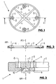
- Die Erfindung wird im Folgenden anhand der Figuren an Ausführungsbeispielen näher erläutert. Es zeigen:
- Fig. 1
- in vereinfachter Darstellung und in Draufsicht den radartigen Schwingkörper eines mechanischen Schwingsystems für Armaturen;
- Fig. 2
- einen Schnitt entsprechend der Linie I - I der
Figur 1 ; - Fig. 3
- in vergrößerter Darstellung eines der am Schwingkörper vorgesehenen Massengewichte zusammen mit einer Teildarstellung des Schwingkörpers;
- Fig. 4
- eine Darstellung wie
Figur 3 bei einer weiteren Ausführungsform der Erfindung; - Fig. 5
- in Teildarstellung eine Draufsicht auf die Unterseite des Schwinkörpers.
- In den Figuren ist 1 ein radartiger Schwingkörper eines mechanischen Schwingsystems (Unruh) für Armbanduhren. Der Schwingkörper 1 ist aus einem geeigneten Werkstoff, beispielsweise aus einem metallischen Werkstoff, bevorzugt aus Molybdän einstückig mit einem äußeren, die Achse AS des Schwingkörpers 1 konzentrisch umschließenden kreisringartigen Abschnitt 2, mit einem inneren, narbenartigen Abschnitt 3 und mit vier den inneren Abschnitt 3 mit dem äußeren Abschnitt 2 verbindenden speichenartigen und radial zur Achse AS sich erstreckenden Stegen 4 ausgebildet. Der Abschnitt 3 ist mit einer Öffnung 5 ausgebildet, die achsgleich mit der Achse AS ausgeführt ist und zum Befestigen des Schwingkörpers 1 an einer nicht dargestellten Welle dient.
- An der Innenseite des äußeren Abschnittes 2 sind in gleichmäßigen Winkelabständen um die Achse des Schwingkörpers verteilt identisch ausgebildete Massengewichte 6 vorgesehen, die jeweils als kreisscheibenförmige Formkörper 7 mit einer eine Achse AM des jeweiligen Formkörpers 7 auf einem Winkelbereich kleiner 360°, d.h. bei der dargestellten Ausführungsform auf einem Winkelbereich von 180° oder im Wesentlichen von 180°umschließenden kreisbogenförmigen Nut 8, die von der Oberseite des Formkörpers 7 bis an dessen Unterseite reicht. Durch die Nut 8 weisen die Massengewichte 6 jeweils einen radial zur Achse AM versetzten Massenschwerpunkt auf.
- Im montierten Zustand sind die Massengewichte 6 bzw. deren Formkörper 7 mit ihrer Achse AM parallel zur Achse AS des Schwingkörpers 1 orientiert. Zur Befestigung der Massengewichte 6, die jeweils in der Mitte zwischen zwei Stegen angeordnet sind, ist der äußere kreisringartige Abschnitt innenliegend einstückig mit laschenartigen Abschnitten oder Laschen 9 ausgebildet, die sich von der Innenseite des Abschnittes 2 radial in Richtung des Abschnittes 3 bzw. der Achse AS erstrecken. Im Bereich des freien Endes sind die Laschen 9 mit jeweils einer geschlossenen Bohrung 10 versehen, deren Achse parallel zur Achse AS orientiert ist. Der Abstand, den die Bohrungen 10 von der Innenfläche des Abschnittes 2 aufweisen ist in etwa gleich bzw. etwas größer als der halbe Durchmesser der kreisscheibenartigen Massengewichte 6 bzw. Formkörper 7. Sämtliche Bohrungen besitzen den selben Abstand von der Achse AS. In jede Bohrung 10 greift ein an der Außenfläche kreiszylinderförmiger, achsgleich mit der Achse AM ausgebildeter und über die Unterseite des Formkörpers 7 weg stehender, angeformter Vorsprung 11 ein, dessen Außendurchmesser gleich dem Innendurchmesser der Bohrung 10 ist. Jeder Vorsprung ist mit einer Bohrung 12 versehen, die an der dem Formkörper 7 abgewandten Stirnseite des Vorsprunges 11 offen ist und bis etwa in den Übergangsbereich zwischen dem Formkörper 7 und den Vorsprung 11 reicht.
- Durch Verstemmen des Vorsprungs 11 ist das jeweilige Massengewicht 6 mit diesem Vorsprung 11 an der zugehörigen Lasche 9 gehalten, und zwar derart, dass der Formkörper 7 mit seiner den Vorsprung 11 aufweisenden und diesen Vorsprung umschließenden Stirnfläche gegen die Oberseite des Vorsprunges 9 anliegt und mit seiner dem Vorsprung 11 abgewandten oberen Stirnseite nicht oder nur geringfügig, beispielsweise nur mit 0 bis 3% seiner gesamten axialen Höhe über die Ebene der Oberseite des Schwingkörpers 1 vorsteht.
- Für das Verstemmen ist jede Bohrung 10 an der dem Formkörper 7 abgewandten Unterseite der Lasche 9 mit einer Phase bzw. mit einem sich zu dieser Unterseite hin kegelstumpfförmig erweiternden Abschnitt versehen, in den hinein der Vorsprung 11 radial zur Achse AM bleibend derart verformt ist, dass dieser verformte Abschnitt des Vorsprungs 11 bündig mit der Ebene der Unterseite der jeweiligen Lasche 9 ist, d.h. über diese Unterseite nicht vorsteht.
- Auch andere Arten eines Verstemmens bzw. Fixierens der Massengewichte 6 an den Laschen 9, beispielsweise durch bleibende Verformung des jeweiligen Vorsprunges 11 unter Ausbildung eines den Rand der Bohrung 10 an der Unterseite der jeweiligen Lasche 9 übergreifenden Wulstes sind möglich. In jedem Fall erfolgt das Verstemmen der Massengewichte 6 derart, dass diese nicht zuverlässig am Schwingkörper 1 gehalten sind, sondern unter Aufwendung eines Drehmomentes für das Justieren des Schwingkörpers 1 bzw. für die Einstellung des Massenträgheitsmomentes dieses schwingkörpers um ihre Achse AM drehbar sind und die jeweilige Einstellung durch die zwischen den Laschen 9 und den Massengewichten 6 wirkenden Reibungskräften zuverlässig gesichert ist. Die Unterseite jeder Lasche 9 liegt in einer gemeinsamen Ebene mit der Unterseite des Schwingkörpers 1 bzw. mit der Unterseite des äußeren kreisringförmigen Abschnittes 2.
- Für den Schwingkörpers 1 wird ein Werkstoff, vorzugsweise ein metallischer Werkstoff verwendet, der einer Dichte über 10 kg/m3 sowie einem thermischen Wärmeausdehnungskoeffizienten kleiner 7×10⁻⁶ sowie eine Mohs-Härte größer 5 aufweist. Der Wärmeausdehnungskoeffizient ist dabei die Längenausdehnungszahl bzw. die Verlängerung einer Längeneinheit bei 1 °C Temperaturerhöhung im Temperaturbereich zwischen 0 bis 100°C.
- Durch die hohe Dichte ergeben sich das erforderliche Massengewicht bzw. das Massenträgheitsmoment für den Schwingkörpers 1. Durch die hohe Härte wird erreicht, dass die Massengewichte 6 nach dem Verstemmen zuverlässig am Schwingkörper 1 gehalten sind und dennoch ein Einstellen des dynamischen Massenträgheitsmomentes des Schwingkörpers 1 durch Drehen bzw. Schwenken der Massengewichte 6 um ihre Achse AM möglich ist. Durch den reduzierten Wärmeausdehnungskoeffizienten werden eine hohe thermische Ganggenauigkeit des Schwingsystems und damit eine hohe Ganggenauigkeit der betreffenden Armbanduhr auch bei wechselnden Temperaturen erreicht.
- Als Material für den Schwingkörpers 1 eignen sich demnach beispielsweise Wolfram, Molybdän, Niob, Hafnium oder diese Metalle in einem hohen Anteil enthaltende Legierungen, bevorzugt Wolfram/Kupfer-Legierungen mit einem Wolfram/Kupfer-Verhältnis 80/20 oder im Wesentlichen 80/20.
- Die Massengewichte 6 bestehen ebenfalls aus einem Material mit hoher Dichte, so dass die Massengewichte 6 mit relativ kleinen Abmessungen gefertigt werden können, beispielsweise derart, dass der Durchmesser des Formkörpers 7 etwa 1,2 Einheiten, die axiale Höhe des Formkörpers 7 etwa 0,35 Einheiten, der Durchmesser des Vorsprungs 11 etwa 0,4 Einheiten und die axiale Länge des Vorsprunges 11 etwa 0,2 Einheiten betragen, wobei eine Einheit beispielsweise 1 mm ist. Bei der dargestellten Ausführungsform beträgt der maximale Durchmesser der Massengewichte 6 etwa 10 bis 12% des Gesamtdurchmessers des Schwingkörpers 1.
- Bei einer Ausführungsform der Erfindung bestehen der Schwingkörper 1 aus Kupfer-Beryllium und die Massengewichte 6 aus Edelstahl.
- Die
Figuren 4 und5 zeigen eine Ausführungsform, bei der die Massengewichte 6 jeweils unter Verwendung eines geschlitzten Klemmrings 13 in der Bohrung 10 klemmend, d.h. derart gehalten sind, dass zwar eine Einstellung des Trägheitsmomentes des Schwingkörpers 1 durch Drehen der Massengewichte 6 möglich ist, ein unerwünschtes Verdrehen der Massengewichte 6 während des Betriebes der entsprechenden Uhr aber nicht eintritt. Die Klemmringe 13 sind aus einem geeigneten metallischen und federnden Werkstoff hergestellt, beispielsweise im sogenannten LIGA-Verfahren. Der angeformte Vorsprung 11 des jeweiligen Massengewichtes 6 ist an seinem freien Ende mit einem von dem Klemmring 13 hintergriffenen Flansch oder Bund 14 ausgebildet. Die Bohrung 10 ist wiederum so ausgeführt, dass sie sich zu der Unterseite des Schwingkörpers 1 bzw. der Lasche 9 konisch erweitert und dadurch einen Freiraum für den Klemmring 13 bildet, der mit seinem äußeren Rand gegen die Unterseite des Schwingkörpers 1 in dem die Bohrung 10 umgebenden Randbereich anliegt, sodass durch die Wirkung des Klemmringes 13 das Massengewicht 6 gegen die Oberseite des Schwingkörpers 1 angepresst wird und dadurch mit Klemmsitz am Schwingkörper 1 gehalten ist. - Ein wesentlicher Vorteil des Schwingsystems 1 besteht darin, dass insbesondere der Schwingkörper 1 eine relativ einfache Formgebung aufweist, die trotz der großen Härte des verwendeten Materials eine vereinfachte Fertigung ermöglicht. Durch die Anordnung der Massengewichte 6 innerhalb des äußeren ringförmigen Abschnittes 2 geht durch die Massengewichte 6 praktisch kein Bauraum für andere Komponenten des mechanischen Schwingsystems bzw. des mechanischen Uhrwerks verloren. Da die Massengewichte 6 insbesondere für das Einstellen des dynamischen Massenträgheitsmomentes dieses Schwingkörpers um ihre Achsen AM parallel zur Achse AS dreh- oder schwenkbar sind, besteht die Möglichkeit einer vereinfachten Einstellung, bei der die Nuten 8 zugleich als Flächen für das Ansetzen eines beim Einstellen verwendeten Werkzeugs benutzt werden können.
- Die Erfindung wurde voranstehend an einem Ausführungsbeispiel beschrieben. Es versteht sich, dass zahlreiche Änderungen sowie Abwandlungen möglich sind, ohne dass der der Erfindung zugrundeliegende Erfindungsgedanke verlassen wird.
-
- 1
- Schwingkörper
- 2
- kreisringförmiger Abschnitt des Schwingkörpers
- 3
- innerer narbenartiger Abschnitt des Schwingkörpers
- 4
- Steg
- 5
- Öffnung
- 6
- Massengewicht
- 7
- Formkörper
- 8
- Schlitz oder Ausnehmung
- 9
- Vorsprung oder Lasche
- 10
- Bohrung
- 11
- Vorsprung
- 12
- Bohrung
- AS
- Mittelachse des Schwingkörper
- AM
- Mittelachse des Massengewichtes 6
Claims (11)
- Schwingkörper für mechanische Schwingsysteme von Armbanduhren, mit mehreren um eine Schwingkörpermittelachse (AS) in gleichmäßigen Winkelabständen angeordneten Massengewichten (6), die einen gegenüber ihrer Achse (AM) radial versetzten Masseschwerpunkt aufweisen und jeweils um ihre Achse (AM) parallel zu der Schwingkörperarchse (AS) dreh- oder schwenkbar am Schwingkörper (1) vorgesehen sind,
dadurch gekennzeichnet,
dass jedes Massegewicht (6) mit wenigstens einem Vorsprung (11) in einer achsgleich mit der Achse (AM) des Massengewichtes (6) ausgebildeten Bohrung (10) des Schwingkörpers (1) klemmend gehalten ist. - Schwingkörper nach Anspruch 1, dadurch gekennzeichnet, dass jedes Massengewicht (6) durch Verstemmen bzw. durch bleibende Verformung eines Teilabschnittes des Vorsprungs (11) und/oder unter Verwendung eines Klemmrings (13) am Schwingkörper (1) gehalten ist.
- Schwingkörper nach Anspruch 1 oder 2, dadurch gekennzeichnet, dass der Schwingkörper (1) aus einem Werkstoff, vorzugsweise aus einem metallischen Werkstoff gefertigt ist, der eine Dichte größer 10 kg/m3, eine Mohs-Härte größer 5 sowie einen Längenausdehnungskoeffizienten kleiner 7 10-6 aufweist.
- Schwingkörper nach Anspruch 3, dadurch gekennzeichnet, dass der Schwingkörper (1) aus Wolfram, Molybdän, Hafnium, Niob oder einer diese Komponenten enthaltenden Legierung, vorzugsweise aus einer Wolfram/Kupferlegierung, oder aus Kupfer-Beryllium gefertigt ist.
- Schwingkörper nach einem der vorhergehenden Ansprüche, dadurch gekennzeichnet, dass die Massengewichte aus Gold oder Messing oder Edelstahl gefertigt sind.
- Schwingkörper nach einem der vorhergehenden Ansprüche, dadurch gekennzeichnet, dass die Massengewichte (6) innerhalb des Schwingkörpers (1) vorgesehen sind und insbesondere nicht, allenfalls nur geringfügig über eine Oberseite und Unterseite des Schwingkörpers (1) vorstehen.
- Schwingkörper nach einem der vorhergehenden Ansprüche, dadurch gekennzeichnet, dass der maximale Durchmesser der Massengewichte (6) etwa 10 bis 12% des Gesamtdurchmessers des Schwingkörpers (1) beträgt.
- Schwingkörper nach einem der vorhergehenden Ansprüche, dadurch gekennzeichnet, dass er mit einem äußeren kreisringartigen Abschnitt (2) mit von der Innenseite dieses Abschnittes in Richtung zur Schwingkörperachse (AS) wegstehenden Haltelaschen (9) ausgebildet ist, und dass die Massengewichte (6) jeweils an eine Haltelasche (9) durch Verstemmen gehalten sind.
- Schwingkörper nach einem der vorhergehenden Ansprüche, dadurch gekennzeichnet, dass die Massengewichte (6) jeweils kreisscheibenartig mit einer Ausnehmung (8) ausgebildet sind, die die Achse (AM) des Massengewichtes (6) auf einem Teilkreis, beispielsweise auf einem Winkelbereich zwischen 90 und 200°, vorzugsweise auf einen Winkelbereich von 180° oder im Wesentlichen von 180° umschließt.
- Mechanisches Schwingsystem für Armbanduhren mit einem Schwingkörper (1), dadurch gekennzeichnet, dass der Schwingkörper nach einem der vorhergehenden Ansprüche ausgebildet ist.
- Uhr, insbesondere Armbanduhr mit einem mechanischen Schwingsystem gemäß Patentanspruch 10.
Applications Claiming Priority (3)
| Application Number | Priority Date | Filing Date | Title |
|---|---|---|---|
| DE102010033668 | 2010-08-06 | ||
| DE102010049210 | 2010-10-21 | ||
| DE102011109220A DE102011109220A1 (de) | 2010-08-06 | 2011-08-03 | Schwingkörper, mechanisches Schwingsystem für Armbanduhren mit einem solchen Schwingkörper sowie Uhr mit einem derartigen Schwingsystem |
Publications (3)
| Publication Number | Publication Date |
|---|---|
| EP2420900A2 true EP2420900A2 (de) | 2012-02-22 |
| EP2420900A3 EP2420900A3 (de) | 2012-02-29 |
| EP2420900B1 EP2420900B1 (de) | 2019-02-27 |
Family
ID=44674034
Family Applications (1)
| Application Number | Title | Priority Date | Filing Date |
|---|---|---|---|
| EP11006373.2A Active EP2420900B1 (de) | 2010-08-06 | 2011-08-03 | Schwingkörper, mechanisches Schwingsystem für Armbanduhren mit einem solchen Schwingkörper sowie Uhr mit einem derartigen Schwingsystem |
Country Status (3)
| Country | Link |
|---|---|
| US (1) | US8662742B2 (de) |
| EP (1) | EP2420900B1 (de) |
| DE (2) | DE102011109220A1 (de) |
Cited By (1)
| Publication number | Priority date | Publication date | Assignee | Title |
|---|---|---|---|---|
| EP3144742A1 (de) * | 2015-09-18 | 2017-03-22 | ETA SA Manufacture Horlogère Suisse | Mikroregulierung der unruhträgheit eines uhrwerks |
Families Citing this family (13)
| Publication number | Priority date | Publication date | Assignee | Title |
|---|---|---|---|---|
| EP2410386B1 (de) * | 2010-07-19 | 2018-10-03 | Nivarox-FAR S.A. | Unruh mit Trägheitsregulierung mit Einsatzteil |
| EP2455825B1 (de) * | 2010-11-18 | 2016-08-17 | Nivarox-FAR S.A. | Verfahren zur Paarung und Angleichung einer Untereinheit einer Uhr |
| EP3376306A1 (de) * | 2011-12-22 | 2018-09-19 | The Swatch Group Research and Development Ltd | Bewegliches element für wissenschaftliches instrument oder zeitmesser |
| USD700535S1 (en) * | 2011-12-28 | 2014-03-04 | Nivarox-Far S.A. | Balance wheel with control knobs |
| JP6007082B2 (ja) * | 2012-03-14 | 2016-10-12 | セイコーインスツル株式会社 | 時計用錘、時計用錘を備える時計用ムーブメント及び時計 |
| JP2013195297A (ja) * | 2012-03-21 | 2013-09-30 | Seiko Instruments Inc | てんぷ構造体及び機械式時計 |
| US10314492B2 (en) | 2013-05-23 | 2019-06-11 | Medibotics Llc | Wearable spectroscopic sensor to measure food consumption based on interaction between light and the human body |
| US9582035B2 (en) | 2014-02-25 | 2017-02-28 | Medibotics Llc | Wearable computing devices and methods for the wrist and/or forearm |
| US10429888B2 (en) | 2014-02-25 | 2019-10-01 | Medibotics Llc | Wearable computer display devices for the forearm, wrist, and/or hand |
| EP2952977A1 (de) * | 2014-06-03 | 2015-12-09 | Nivarox-FAR S.A. | Uhrkomponente aus geschweißten Materialien |
| EP2990883A1 (de) * | 2014-08-29 | 2016-03-02 | Nivarox-FAR S.A. | Spiralunruh-Einheit für Uhrwerk |
| EP3021173B1 (de) * | 2014-11-14 | 2017-05-24 | Blancpain S.A. | Ringförmige Schwungmasse und Uhr, die eine solche Schwungmasse umfasst |
| EP3647883B1 (de) * | 2018-11-05 | 2025-01-01 | CSEM Centre Suisse D'electronique Et De Microtechnique SA | Unruh einer uhr |
Family Cites Families (8)
| Publication number | Priority date | Publication date | Assignee | Title |
|---|---|---|---|---|
| US1350035A (en) * | 1920-03-02 | 1920-08-17 | Povelsen Ingild | Compensating balance-wheel |
| US2880570A (en) * | 1956-11-26 | 1959-04-07 | Elgin Nat Watch Co | Balance with adjustable moment of inertia |
| CH343904A (fr) * | 1959-06-03 | 1959-12-31 | Rolex Montres | Balancier pour pièce d'horlogerie |
| DE60227912D1 (de) * | 2002-03-21 | 2008-09-11 | Chopard Manufacture Sa | Unruh mit Verstellmechanismus |
| EP1705534A1 (de) * | 2005-03-23 | 2006-09-27 | Patek Philippe Sa | Trägheitsunruh |
| ATE433137T1 (de) * | 2006-03-24 | 2009-06-15 | Nivarox Sa | Unruh für uhrwerk |
| WO2008029158A2 (en) * | 2006-09-08 | 2008-03-13 | Gideon Levingston | Thermally compensating balance wheel |
| US8240910B2 (en) * | 2006-12-21 | 2012-08-14 | Complitime S.A. | Mechanical oscillator for timepiece |
-
2011
- 2011-08-03 DE DE102011109220A patent/DE102011109220A1/de not_active Withdrawn
- 2011-08-03 DE DE202011110747.0U patent/DE202011110747U1/de not_active Expired - Lifetime
- 2011-08-03 EP EP11006373.2A patent/EP2420900B1/de active Active
- 2011-08-04 US US13/198,153 patent/US8662742B2/en not_active Expired - Fee Related
Non-Patent Citations (1)
| Title |
|---|
| None |
Cited By (1)
| Publication number | Priority date | Publication date | Assignee | Title |
|---|---|---|---|---|
| EP3144742A1 (de) * | 2015-09-18 | 2017-03-22 | ETA SA Manufacture Horlogère Suisse | Mikroregulierung der unruhträgheit eines uhrwerks |
Also Published As
| Publication number | Publication date |
|---|---|
| EP2420900A3 (de) | 2012-02-29 |
| DE202011110747U1 (de) | 2016-01-14 |
| EP2420900B1 (de) | 2019-02-27 |
| US20120087214A1 (en) | 2012-04-12 |
| DE102011109220A1 (de) | 2012-02-09 |
| US8662742B2 (en) | 2014-03-04 |
Similar Documents
| Publication | Publication Date | Title |
|---|---|---|
| EP2420900B1 (de) | Schwingkörper, mechanisches Schwingsystem für Armbanduhren mit einem solchen Schwingkörper sowie Uhr mit einem derartigen Schwingsystem | |
| EP2318167B1 (de) | Rundlaufendes schaftwerkzeug | |
| DE102007018920B3 (de) | Antriebswelle | |
| DE102004061871B4 (de) | Spannvorrichtung mit Zentriervorrichtung an einem Schleifspindelrotor und Rotationsteil mit einer derartigen Zentriervorrichtung | |
| EP3260716B1 (de) | Kippsegmentlager | |
| EP2894373B1 (de) | Spielfreie Spindelmutter | |
| EP2019214A2 (de) | Einpresselement zum Einpressen in ein nicht gelochtes oder gelochtes Bauteil sowie Verfahren zur Herstellung des Einpresselements | |
| DE102021205788A1 (de) | Loslageranordnung | |
| EP2604368A1 (de) | Bearbeitungswerkzeug | |
| DE102004042478B4 (de) | Verfahren zur verdrehsicheren Befestigung eines Funktionselements in einem Bauteil sowie Verbindung zwischen einem Bauteil und einem Funktionselement | |
| EP1469208B1 (de) | Schraubelement mit einem angeformten Federelement | |
| EP3807012B1 (de) | Zentrifuge | |
| DE10215314A1 (de) | Vorrichtung zum verspannenden Verbinden von mit Abstand zueinander liegenden Bauteilen | |
| DE102013220627B3 (de) | Verfahren zum Befestigen eines Zuganschlags an einer Kolbenstange eines Schwingungsdämpfers | |
| DE2751603A1 (de) | Stossdaempfendes lager fuer uhrwerke | |
| DE202010014253U1 (de) | Schwingsystem für mechanische Uhrwerke | |
| EP3283001B1 (de) | Spannvorrichtung zum einspannen eines zylinderförmigen werkzeugschafts | |
| DE102014219705A1 (de) | Lagerring | |
| EP1905545A2 (de) | Federspanner für Schraubenfedern | |
| EP3477127B1 (de) | Schraube zum einschrauben in ein bohrloch | |
| DE19961709A1 (de) | Befestigungseinrichtung für eine Lagerung einer Spindel | |
| DE102019116238A1 (de) | Drehmomentbegrenzungseinrichtung und Verfahren zu dessen Kalibrierung | |
| DE10333754B4 (de) | Sperrscheibe zum Sichern von Teilen in einem zylindrischen Hohlraum | |
| EP3356618B1 (de) | Baustütze | |
| DE102014112603B4 (de) | Werkzeughalter mit Radialspielausgleich |
Legal Events
| Date | Code | Title | Description |
|---|---|---|---|
| PUAL | Search report despatched |
Free format text: ORIGINAL CODE: 0009013 |
|
| AK | Designated contracting states |
Kind code of ref document: A2 Designated state(s): AL AT BE BG CH CY CZ DE DK EE ES FI FR GB GR HR HU IE IS IT LI LT LU LV MC MK MT NL NO PL PT RO RS SE SI SK SM TR |
|
| AX | Request for extension of the european patent |
Extension state: BA ME |
|
| PUAI | Public reference made under article 153(3) epc to a published international application that has entered the european phase |
Free format text: ORIGINAL CODE: 0009012 |
|
| AK | Designated contracting states |
Kind code of ref document: A3 Designated state(s): AL AT BE BG CH CY CZ DE DK EE ES FI FR GB GR HR HU IE IS IT LI LT LU LV MC MK MT NL NO PL PT RO RS SE SI SK SM TR |
|
| AX | Request for extension of the european patent |
Extension state: BA ME |
|
| RIC1 | Information provided on ipc code assigned before grant |
Ipc: G04B 17/06 20060101AFI20120126BHEP |
|
| 17P | Request for examination filed |
Effective date: 20120827 |
|
| RAP1 | Party data changed (applicant data changed or rights of an application transferred) |
Owner name: DAMASKO GMBH |
|
| RIN1 | Information on inventor provided before grant (corrected) |
Inventor name: DAMASKO, PETRA |
|
| STAA | Information on the status of an ep patent application or granted ep patent |
Free format text: STATUS: EXAMINATION IS IN PROGRESS |
|
| 17Q | First examination report despatched |
Effective date: 20161129 |
|
| GRAP | Despatch of communication of intention to grant a patent |
Free format text: ORIGINAL CODE: EPIDOSNIGR1 |
|
| STAA | Information on the status of an ep patent application or granted ep patent |
Free format text: STATUS: GRANT OF PATENT IS INTENDED |
|
| INTG | Intention to grant announced |
Effective date: 20180911 |
|
| GRAS | Grant fee paid |
Free format text: ORIGINAL CODE: EPIDOSNIGR3 |
|
| GRAA | (expected) grant |
Free format text: ORIGINAL CODE: 0009210 |
|
| STAA | Information on the status of an ep patent application or granted ep patent |
Free format text: STATUS: THE PATENT HAS BEEN GRANTED |
|
| AK | Designated contracting states |
Kind code of ref document: B1 Designated state(s): AL AT BE BG CH CY CZ DE DK EE ES FI FR GB GR HR HU IE IS IT LI LT LU LV MC MK MT NL NO PL PT RO RS SE SI SK SM TR |
|
| REG | Reference to a national code |
Ref country code: GB Ref legal event code: FG4D Free format text: NOT ENGLISH |
|
| REG | Reference to a national code |
Ref country code: CH Ref legal event code: EP |
|
| REG | Reference to a national code |
Ref country code: AT Ref legal event code: REF Ref document number: 1102272 Country of ref document: AT Kind code of ref document: T Effective date: 20190315 |
|
| REG | Reference to a national code |
Ref country code: IE Ref legal event code: FG4D Free format text: LANGUAGE OF EP DOCUMENT: GERMAN |
|
| REG | Reference to a national code |
Ref country code: DE Ref legal event code: R096 Ref document number: 502011015386 Country of ref document: DE |
|
| REG | Reference to a national code |
Ref country code: NL Ref legal event code: MP Effective date: 20190227 |
|
| REG | Reference to a national code |
Ref country code: LT Ref legal event code: MG4D |
|
| PG25 | Lapsed in a contracting state [announced via postgrant information from national office to epo] |
Ref country code: NL Free format text: LAPSE BECAUSE OF FAILURE TO SUBMIT A TRANSLATION OF THE DESCRIPTION OR TO PAY THE FEE WITHIN THE PRESCRIBED TIME-LIMIT Effective date: 20190227 Ref country code: LT Free format text: LAPSE BECAUSE OF FAILURE TO SUBMIT A TRANSLATION OF THE DESCRIPTION OR TO PAY THE FEE WITHIN THE PRESCRIBED TIME-LIMIT Effective date: 20190227 Ref country code: FI Free format text: LAPSE BECAUSE OF FAILURE TO SUBMIT A TRANSLATION OF THE DESCRIPTION OR TO PAY THE FEE WITHIN THE PRESCRIBED TIME-LIMIT Effective date: 20190227 Ref country code: SE Free format text: LAPSE BECAUSE OF FAILURE TO SUBMIT A TRANSLATION OF THE DESCRIPTION OR TO PAY THE FEE WITHIN THE PRESCRIBED TIME-LIMIT Effective date: 20190227 Ref country code: PT Free format text: LAPSE BECAUSE OF FAILURE TO SUBMIT A TRANSLATION OF THE DESCRIPTION OR TO PAY THE FEE WITHIN THE PRESCRIBED TIME-LIMIT Effective date: 20190627 Ref country code: NO Free format text: LAPSE BECAUSE OF FAILURE TO SUBMIT A TRANSLATION OF THE DESCRIPTION OR TO PAY THE FEE WITHIN THE PRESCRIBED TIME-LIMIT Effective date: 20190527 |
|
| PG25 | Lapsed in a contracting state [announced via postgrant information from national office to epo] |
Ref country code: BG Free format text: LAPSE BECAUSE OF FAILURE TO SUBMIT A TRANSLATION OF THE DESCRIPTION OR TO PAY THE FEE WITHIN THE PRESCRIBED TIME-LIMIT Effective date: 20190527 Ref country code: RS Free format text: LAPSE BECAUSE OF FAILURE TO SUBMIT A TRANSLATION OF THE DESCRIPTION OR TO PAY THE FEE WITHIN THE PRESCRIBED TIME-LIMIT Effective date: 20190227 Ref country code: LV Free format text: LAPSE BECAUSE OF FAILURE TO SUBMIT A TRANSLATION OF THE DESCRIPTION OR TO PAY THE FEE WITHIN THE PRESCRIBED TIME-LIMIT Effective date: 20190227 Ref country code: IS Free format text: LAPSE BECAUSE OF FAILURE TO SUBMIT A TRANSLATION OF THE DESCRIPTION OR TO PAY THE FEE WITHIN THE PRESCRIBED TIME-LIMIT Effective date: 20190627 Ref country code: HR Free format text: LAPSE BECAUSE OF FAILURE TO SUBMIT A TRANSLATION OF THE DESCRIPTION OR TO PAY THE FEE WITHIN THE PRESCRIBED TIME-LIMIT Effective date: 20190227 Ref country code: GR Free format text: LAPSE BECAUSE OF FAILURE TO SUBMIT A TRANSLATION OF THE DESCRIPTION OR TO PAY THE FEE WITHIN THE PRESCRIBED TIME-LIMIT Effective date: 20190528 |
|
| PG25 | Lapsed in a contracting state [announced via postgrant information from national office to epo] |
Ref country code: SK Free format text: LAPSE BECAUSE OF FAILURE TO SUBMIT A TRANSLATION OF THE DESCRIPTION OR TO PAY THE FEE WITHIN THE PRESCRIBED TIME-LIMIT Effective date: 20190227 Ref country code: IT Free format text: LAPSE BECAUSE OF FAILURE TO SUBMIT A TRANSLATION OF THE DESCRIPTION OR TO PAY THE FEE WITHIN THE PRESCRIBED TIME-LIMIT Effective date: 20190227 Ref country code: EE Free format text: LAPSE BECAUSE OF FAILURE TO SUBMIT A TRANSLATION OF THE DESCRIPTION OR TO PAY THE FEE WITHIN THE PRESCRIBED TIME-LIMIT Effective date: 20190227 Ref country code: CZ Free format text: LAPSE BECAUSE OF FAILURE TO SUBMIT A TRANSLATION OF THE DESCRIPTION OR TO PAY THE FEE WITHIN THE PRESCRIBED TIME-LIMIT Effective date: 20190227 Ref country code: RO Free format text: LAPSE BECAUSE OF FAILURE TO SUBMIT A TRANSLATION OF THE DESCRIPTION OR TO PAY THE FEE WITHIN THE PRESCRIBED TIME-LIMIT Effective date: 20190227 Ref country code: ES Free format text: LAPSE BECAUSE OF FAILURE TO SUBMIT A TRANSLATION OF THE DESCRIPTION OR TO PAY THE FEE WITHIN THE PRESCRIBED TIME-LIMIT Effective date: 20190227 Ref country code: AL Free format text: LAPSE BECAUSE OF FAILURE TO SUBMIT A TRANSLATION OF THE DESCRIPTION OR TO PAY THE FEE WITHIN THE PRESCRIBED TIME-LIMIT Effective date: 20190227 Ref country code: DK Free format text: LAPSE BECAUSE OF FAILURE TO SUBMIT A TRANSLATION OF THE DESCRIPTION OR TO PAY THE FEE WITHIN THE PRESCRIBED TIME-LIMIT Effective date: 20190227 |
|
| REG | Reference to a national code |
Ref country code: DE Ref legal event code: R097 Ref document number: 502011015386 Country of ref document: DE |
|
| PG25 | Lapsed in a contracting state [announced via postgrant information from national office to epo] |
Ref country code: PL Free format text: LAPSE BECAUSE OF FAILURE TO SUBMIT A TRANSLATION OF THE DESCRIPTION OR TO PAY THE FEE WITHIN THE PRESCRIBED TIME-LIMIT Effective date: 20190227 Ref country code: SM Free format text: LAPSE BECAUSE OF FAILURE TO SUBMIT A TRANSLATION OF THE DESCRIPTION OR TO PAY THE FEE WITHIN THE PRESCRIBED TIME-LIMIT Effective date: 20190227 |
|
| PLBE | No opposition filed within time limit |
Free format text: ORIGINAL CODE: 0009261 |
|
| STAA | Information on the status of an ep patent application or granted ep patent |
Free format text: STATUS: NO OPPOSITION FILED WITHIN TIME LIMIT |
|
| 26N | No opposition filed |
Effective date: 20191128 |
|
| PG25 | Lapsed in a contracting state [announced via postgrant information from national office to epo] |
Ref country code: SI Free format text: LAPSE BECAUSE OF FAILURE TO SUBMIT A TRANSLATION OF THE DESCRIPTION OR TO PAY THE FEE WITHIN THE PRESCRIBED TIME-LIMIT Effective date: 20190227 |
|
| PG25 | Lapsed in a contracting state [announced via postgrant information from national office to epo] |
Ref country code: TR Free format text: LAPSE BECAUSE OF FAILURE TO SUBMIT A TRANSLATION OF THE DESCRIPTION OR TO PAY THE FEE WITHIN THE PRESCRIBED TIME-LIMIT Effective date: 20190227 |
|
| GBPC | Gb: european patent ceased through non-payment of renewal fee |
Effective date: 20190803 |
|
| PG25 | Lapsed in a contracting state [announced via postgrant information from national office to epo] |
Ref country code: LU Free format text: LAPSE BECAUSE OF NON-PAYMENT OF DUE FEES Effective date: 20190803 Ref country code: MC Free format text: LAPSE BECAUSE OF FAILURE TO SUBMIT A TRANSLATION OF THE DESCRIPTION OR TO PAY THE FEE WITHIN THE PRESCRIBED TIME-LIMIT Effective date: 20190227 |
|
| REG | Reference to a national code |
Ref country code: BE Ref legal event code: MM Effective date: 20190831 |
|
| PG25 | Lapsed in a contracting state [announced via postgrant information from national office to epo] |
Ref country code: FR Free format text: LAPSE BECAUSE OF NON-PAYMENT OF DUE FEES Effective date: 20190831 Ref country code: IE Free format text: LAPSE BECAUSE OF NON-PAYMENT OF DUE FEES Effective date: 20190803 |
|
| PG25 | Lapsed in a contracting state [announced via postgrant information from national office to epo] |
Ref country code: GB Free format text: LAPSE BECAUSE OF NON-PAYMENT OF DUE FEES Effective date: 20190803 Ref country code: BE Free format text: LAPSE BECAUSE OF NON-PAYMENT OF DUE FEES Effective date: 20190831 |
|
| REG | Reference to a national code |
Ref country code: AT Ref legal event code: MM01 Ref document number: 1102272 Country of ref document: AT Kind code of ref document: T Effective date: 20190803 |
|
| PG25 | Lapsed in a contracting state [announced via postgrant information from national office to epo] |
Ref country code: AT Free format text: LAPSE BECAUSE OF NON-PAYMENT OF DUE FEES Effective date: 20190803 |
|
| PG25 | Lapsed in a contracting state [announced via postgrant information from national office to epo] |
Ref country code: CY Free format text: LAPSE BECAUSE OF FAILURE TO SUBMIT A TRANSLATION OF THE DESCRIPTION OR TO PAY THE FEE WITHIN THE PRESCRIBED TIME-LIMIT Effective date: 20190227 |
|
| PG25 | Lapsed in a contracting state [announced via postgrant information from national office to epo] |
Ref country code: MT Free format text: LAPSE BECAUSE OF FAILURE TO SUBMIT A TRANSLATION OF THE DESCRIPTION OR TO PAY THE FEE WITHIN THE PRESCRIBED TIME-LIMIT Effective date: 20190227 Ref country code: HU Free format text: LAPSE BECAUSE OF FAILURE TO SUBMIT A TRANSLATION OF THE DESCRIPTION OR TO PAY THE FEE WITHIN THE PRESCRIBED TIME-LIMIT; INVALID AB INITIO Effective date: 20110803 |
|
| PG25 | Lapsed in a contracting state [announced via postgrant information from national office to epo] |
Ref country code: MK Free format text: LAPSE BECAUSE OF FAILURE TO SUBMIT A TRANSLATION OF THE DESCRIPTION OR TO PAY THE FEE WITHIN THE PRESCRIBED TIME-LIMIT Effective date: 20190227 |
|
| PGFP | Annual fee paid to national office [announced via postgrant information from national office to epo] |
Ref country code: CH Payment date: 20250901 Year of fee payment: 15 |
|
| PGFP | Annual fee paid to national office [announced via postgrant information from national office to epo] |
Ref country code: DE Payment date: 20251029 Year of fee payment: 15 |