EP2420458A2 - Behälter mit flexibler Lasche - Google Patents
Behälter mit flexibler Lasche Download PDFInfo
- Publication number
- EP2420458A2 EP2420458A2 EP11177608A EP11177608A EP2420458A2 EP 2420458 A2 EP2420458 A2 EP 2420458A2 EP 11177608 A EP11177608 A EP 11177608A EP 11177608 A EP11177608 A EP 11177608A EP 2420458 A2 EP2420458 A2 EP 2420458A2
- Authority
- EP
- European Patent Office
- Prior art keywords
- container
- moving
- latch
- lid
- lifting arm
- Prior art date
- Legal status (The legal status is an assumption and is not a legal conclusion. Google has not performed a legal analysis and makes no representation as to the accuracy of the status listed.)
- Withdrawn
Links
- 238000000034 method Methods 0.000 claims description 7
- 241001465754 Metazoa Species 0.000 description 4
- 239000010813 municipal solid waste Substances 0.000 description 4
- 230000005484 gravity Effects 0.000 description 3
- 239000000463 material Substances 0.000 description 2
- 239000002184 metal Substances 0.000 description 2
- 239000004033 plastic Substances 0.000 description 2
- 239000002699 waste material Substances 0.000 description 2
- 239000004677 Nylon Substances 0.000 description 1
- 241000282330 Procyon lotor Species 0.000 description 1
- XUIMIQQOPSSXEZ-UHFFFAOYSA-N Silicon Chemical compound [Si] XUIMIQQOPSSXEZ-UHFFFAOYSA-N 0.000 description 1
- 230000009471 action Effects 0.000 description 1
- 230000004913 activation Effects 0.000 description 1
- 238000010276 construction Methods 0.000 description 1
- 239000004519 grease Substances 0.000 description 1
- 238000009434 installation Methods 0.000 description 1
- 210000003141 lower extremity Anatomy 0.000 description 1
- 239000000314 lubricant Substances 0.000 description 1
- 230000007246 mechanism Effects 0.000 description 1
- 229920001778 nylon Polymers 0.000 description 1
- 239000003921 oil Substances 0.000 description 1
- 230000037361 pathway Effects 0.000 description 1
- 239000010703 silicon Substances 0.000 description 1
- 229910052710 silicon Inorganic materials 0.000 description 1
- 239000007921 spray Substances 0.000 description 1
Images


Classifications
-
- B—PERFORMING OPERATIONS; TRANSPORTING
- B65—CONVEYING; PACKING; STORING; HANDLING THIN OR FILAMENTARY MATERIAL
- B65F—GATHERING OR REMOVAL OF DOMESTIC OR LIKE REFUSE
- B65F1/00—Refuse receptacles; Accessories therefor
- B65F1/14—Other constructional features; Accessories
- B65F1/16—Lids or covers
- B65F1/1615—Lids or covers with means for locking, fastening or permanently closing thereof
-
- B—PERFORMING OPERATIONS; TRANSPORTING
- B65—CONVEYING; PACKING; STORING; HANDLING THIN OR FILAMENTARY MATERIAL
- B65F—GATHERING OR REMOVAL OF DOMESTIC OR LIKE REFUSE
- B65F1/00—Refuse receptacles; Accessories therefor
- B65F1/02—Refuse receptacles; Accessories therefor without removable inserts
-
- B—PERFORMING OPERATIONS; TRANSPORTING
- B65—CONVEYING; PACKING; STORING; HANDLING THIN OR FILAMENTARY MATERIAL
- B65F—GATHERING OR REMOVAL OF DOMESTIC OR LIKE REFUSE
- B65F1/00—Refuse receptacles; Accessories therefor
- B65F1/14—Other constructional features; Accessories
- B65F1/1468—Means for facilitating the transport of the receptacle, e.g. wheels, rolls
-
- B—PERFORMING OPERATIONS; TRANSPORTING
- B65—CONVEYING; PACKING; STORING; HANDLING THIN OR FILAMENTARY MATERIAL
- B65F—GATHERING OR REMOVAL OF DOMESTIC OR LIKE REFUSE
- B65F1/00—Refuse receptacles; Accessories therefor
- B65F1/14—Other constructional features; Accessories
- B65F1/16—Lids or covers
-
- B—PERFORMING OPERATIONS; TRANSPORTING
- B65—CONVEYING; PACKING; STORING; HANDLING THIN OR FILAMENTARY MATERIAL
- B65F—GATHERING OR REMOVAL OF DOMESTIC OR LIKE REFUSE
- B65F3/00—Vehicles particularly adapted for collecting refuse
- B65F3/02—Vehicles particularly adapted for collecting refuse with means for discharging refuse receptacles thereinto
- B65F2003/0223—Vehicles particularly adapted for collecting refuse with means for discharging refuse receptacles thereinto the discharging means comprising elements for holding the receptacle
- B65F2003/023—Gripper arms for embracing the receptacle
-
- B—PERFORMING OPERATIONS; TRANSPORTING
- B65—CONVEYING; PACKING; STORING; HANDLING THIN OR FILAMENTARY MATERIAL
- B65F—GATHERING OR REMOVAL OF DOMESTIC OR LIKE REFUSE
- B65F3/00—Vehicles particularly adapted for collecting refuse
- B65F3/02—Vehicles particularly adapted for collecting refuse with means for discharging refuse receptacles thereinto
- B65F2003/0286—Means mounted on the vehicle for opening the lid or cover of the receptacle
- B65F2003/0289—Means mounted on the vehicle for opening the lid or cover of the receptacle the opening means being mounted on the discharging means
Definitions
- the present invention is directed to a latch for closing a container lid to a container, and a system and a method for opening a latched container.
- Containers such as garbage containers for homes are known in the art.
- the containers have a container body.
- wheels may be provided at a lower corner of the container body.
- a lid is rotatably affixed to the container to rotate between a first open position and a second closed position.
- latches are provided. These latches are usually metal pieces.
- a metal piece formed as a rod is pivotally mounted to the lid.
- the rod forms a general U-shape in which a first end of the rod is mounted to the lid and the second opposed end of the wire is also mounted to an opposed position on the lid so that the U-shaped rod is pivotally mounted to the lid.
- the base of the U may be formed as a handle.
- the sections between the handle and the respective rod ends form, at least in part, an engaging portion for engaging a lip of the container body.
- engaging portions of the latch engage a portion of the container body locking the lid against the container body.
- the handle is pulled to rotate the latch from the second position releasing the lid from the container body allowing the lid to be rotated into an open position.
- a container comprising a body and a lid rotatably affixed to the body so as to be selectively rotated between a first open position and a second closed position.
- a latch has a first end adapted to be rotatably affixed to the lid.
- a second end is adapted to engage the body. The first end is connected to the second end by an arched member, the arched member capable of flexure when a force is applied at a concave surface of the arched member.
- a lifting arm for emptying a container into a truck comprising an arm having a proximal end, adapted to be affixed to a truck, and a distal end, a manipulating assembly affixed to the arm at the distal end, the manipulating assembly including a grabber member for engaging the container when disposed within the grabber member; a moving member capable of moving between a first position and a second position, the moving member unlatching the container held by the grabber member by moving from the first position to the second position.
- a method for unlatching a latched container comprising providing a lifting arm for lifting the latched container; moving the latched container from a first position to a second position with the lifting arm; an unlatching the container by moving the container from the first position to the second position.
- a system for unlatching a latched container comprising a container having a body; a lid rotatably affixed to the body and movable between a first position and a second position; and a latch pivotably mounted on the lid for selectively locking the lid in a closed position, the latch having a first member adapted to be pivotably mounted to the lid, a second member adapted to selectively engage a projection on the body; and an arched member connecting the first member to the second member; and a lifting arm comprising an arm having a proximal end adapted to be affixed to a truck and a distal end; a manipulating assembly affixed to the arm at the distal end, the manipulating assembly including a grabber member for engaging the container when disposed within the grabber member; a moving member capable of moving between a first position and a second position, the moving member unlatching the container by moving from the first position to the second position.
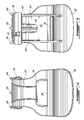
- Figure 1 is a perspective view of a container constructed in accordance with the invention
- Figure 2 is a perspective view of a latch constructed in accordance with the invention.
- Figure 3 is a side elevation view of a latch constructed in accordance with the invention.
- Figure 4 is a front elevation view of a latch constructed in accordance with the invention.
- Figure 5 is a rear elevation view of a latch constructed in accordance with the invention.
- Figure 6 is a top plan view of a latch constructed in accordance with the invention.
- Figure 7 is a bottom plan view of a latch constructed in accordance with the invention.
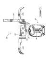
- Figure 8 is a perspective view of the container showing the latch in an open position
- Figure 9 is a side elevation view of the container showing the latch in the closed position in accordance with the invention.
- Figure 10 is a side elevation view of the container showing the latch in an intermediate position in accordance with the invention.
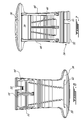
- Figure 11 is a top plan view of a system according to an embodiment of an aspect of the invention, prior to activation;
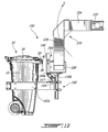
- Figure 12 is a side plan view of a system according to an embodiment of an aspect of the invention, in a first position in which the container is grasped;
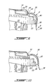
- Figure 13 is a top plan view of a system according to an embodiment of an aspect of the invention, showing the container grasped;
- Figure 14 is a side elevation view of a system according to an embodiment of an aspect of the invention, with the container disposed between the first and second position.
- Container 10 includes a container body 12 having a projection in the form of an upper rim 22 extending about a top, and the opening formed at the top of body 12. Support members 16 extend from the rim 22. A handle 18 is supported by support members 16 spaced away from housing 12.
- Wheels 26 are affixed to housing 12 as in a manner known in the art so that container 10 is mobile.
- rim 22 is provided by way of exemplary, but nonlimiting embodiment. Any projection from body 12 is contemplated by the present invention. Rim 22 may merely be a ridge, a lip, a platform, or a projection capable of being engaged by a latch 30. Support member 16 may also extend from body 12, rather than rim 22.
- a lid 14 sized to cover an opening (not shown) of body 12 is rotatably disposed on body 12.
- Lid 14 is formed with wings 20 for rotatably engaging handle 18 as known in the art. In this manner, lid 14 may be moved from a first closed position, as seen in the figures, about the pivot provided by handle 18 to an open position (not shown) to allow access to the container body 12.
- a pivot 24 is formed within lid 14. In a nonlimiting embodiment, pivot 24 is at an edge of lid 14 opposed to an edge from which lid 14 is rotatably affixed to body 12.
- Latch 30 is pivotally disposed about pivot 24 and is adapted to engage a projection such as that formed by rim 22 to lock lid 14 in the closed position. Accordingly, latch 30 is rotatable between a first open position, as shown in Figure 8 , which allows rotation of lid 14 and a closed position, as shown in Figure 9 , which locks the lid 14 to body 12 in the closed position.
- Latch 30 includes a first member 32 which is a pivot member.
- First member 32 is formed with a receiving portion, in an exemplary but nonlimiting embodiment, an opening 34 therein, adapted to receive pivot 24 of lid 14.
- Latch 30 includes a second member 36 acting as a handle.
- An arch member 40 connects first member 32 with second member 36.
- Handle portion 36 is formed with a catch 38.
- Catch 38 is a projection adapted to engage a projection of housing body 12 such as rim 22.
- Pivot member 32, handle 36, and arch member 40 are formed as a unitary construction; preferably formed of a plastic material.
- Arch member 40 is flexible such that a force applied at a convex surface 48 of latch 30 will deflect arch member 40 flattening arch member 40 to lengthen latch 30.
- Arch 40 has sufficient resiliency that it will substantially return to its original shape upon removal of the force at convex surface 48 of arch portion 40.
- a plurality of support archs 44 extend along convex surface 48 between arch member 40 and pivot member 32.
- a second set of support members 46 comprised of one or more support archs, in a nonlimiting exemplary embodiment, extend along a concave surface of arched member 40, and may extend from the handle portion of second member 36 to the pivot portion of second member 32.
- An opening 42 may be provided in second member 36 adjacent catch 38.
- Catch 38 may be any shape capable of engaging a projection from housing 12, such as rim 22 while also being dimensioned to allow for disengagement by flexure of handle 36 as will be discussed below.
- latch 30 is pivotally mounted to lid 14. Pivot 24 is received within opening 34 of pivot 32 of latch 30. To lock container 10, latch 30 is pivoted from a first open position ( Figure 8 ) in a direction of arrow C to an intermediate position ( Figure 10 ).
- latch 30 is dimensioned so that catch 38 is positioned along latch 30 so that when no force is applied to latch 30, catch 38 is disposed at a position in which it does not engage rim 22, in this instance the position is above a bottom surface 23 of the projection provided by rim 22.
- latch 30 is lengthened so that catch 38 moves below bottom surface 23 of rim 22 to engage rim 22.
- Latch 30 is resilient such that once the force in the direction of arrow A is removed, latch 30 will substantially return to its original position.
- catch 38 engaging rim 22 prevents complete return, and therefore the restorative force of latch 30 keeps latch 30 in the closed position by the force applied by catch 38 against lip 22.
- a force in the direction of arrow A not only extends the length of latch 30, but also continues to move handle 30 in the direction of arrow C so that it is the action of pressing against latch 30 at arch member 40 which closes and locks the container as shown in Figures. 1 and 9 .
- handle portion 36 is slightly curved in that portion of second member 36, which extends from catch 38.
- Handle 36 is curved in a direction opposed to the curve of arch member 40, and in an embodiment, to a lesser extent (more obtuse curve) than the curve of arched member 40. This facilitates applying a force in direction of arrow B to latch 30 at handle portion 36. Applying a force at handle portion 36 pulls catch 38 away from rim 22 releasing latch 30 allowing rotation into the open position shown in Figure 8 .
- the surface of catch 38 may be rounded or cammed to allow catch 38 to slide along rim 22 as it is released rather than requiring movement of handle portion 36 sufficient to rotate catch 38 to clear rim 22 or to flatten catch 40.
- Latch 30 must be sufficiently rigid so as to maintain a grip about pivot 24 and sufficiently rigid along its length to maintain catch 38 in position to prevent opening of lid 14.
- latch 30 must be sufficiently flexible to allow flattening of latch 30 without the need for excessive force, i.e. not beyond a manual force easily applied by an ordinary person and to allow handle 36 sufficient movement to allow catch 38 to either be deflected by rim 22 or disengaged by rim 22.
- Latch 30 also exhibits restorative properties so that once released, latch 30 returns to its original shape.
- latch 30 must maintain these properties across a temperature range from -30°C to 30°C.
- latch 30 is unitary nylon construct.
- a slit 35 is formed within pivot member 32. Slit 35 mates with a projection (not shown) formed on lid 14. Slit 35 is off centered along the axis of second member 32 which prevents mistaken installation of latch 30. Latch 30 will only fit about pivot 24 of lid 14 when slit 35 is aligned with the projection guaranteeing normal orientation.
- System 100 includes a container 10 having a latched lid in which a portion of the latch extends below or beyond the lid, such as latch 30 by way of nonlimiting example and a lifting arm constructed as robotic arm 120, by way of nonlimiting example.
- Robotic lifting arm 120 includes a proximal end 122 adapted to be affixed to a truck (not shown) as known in the art.
- Robotic arm 120 has a first section 124 extending from proximal end 122 and a second section 126 extending from first section 124 at an angle.
- Lifting arm 120 is capable of a range of motion as known in the art to enable lifting and dumping of a full container.
- a manipulating assembly 140 is affixed to a distal end 128 of robotic lifting arm 120.
- Manipulating assembly 140 includes a motor block 141 for housing a motor.
- a grabber assembly which, by way of nonlimiting example, includes grabber members 142a, 142b extending from opposed sides of the motor block 141 and move between a first, open, position and a second, closed or pincing, position under the control of a motor (not shown) typically housed in the motor block 141. It is understood that through gearing the motor may be housed anywhere along system 100.
- Grabber members 142a, 142b when in the closed or second position surround and grab the body 12 of the container 10 (see Figures 12 an 13).
- grabber members 142a, 142b Another structure which grabs to lift the container may be substituted for the grabber members 142a, 142b.
- the container 10 When grasped, in accordance with the invention, the container 10 is captured by the grabber members 142a, 142b such that the latch 30 is substantially in facing relationship with the robot lifting arm 120.
- An unlatching member 144 includes a guide member 146, which is a pathway or chute extending from the grabber members 142a, 142b towards the second arm section 126 for example.
- a moving member 147 is disposed within the guide member 146 and is capable of moving within the guide member 146, under the control of gravity, from a first position away from the latch 30 to a second position towards and/or beyond the latch 30.
- the moving member 147 may include wheels, 148a, 148b as shown, to facilitate movement within the guide member 146 of the moving member 147.
- wheels are used as an exemplary, nonlimiting embodiment and may be omitted by utilizing low friction elements such as TeflonTM or lubricant such as oil, grease or silicon spray, or any combination thereof so long as the moving member 147 is capable of substantially consistent movement at a speed sufficient to dislodge the latch 30 as the moving member 147 moves from the first position to the second position as will be described below.
- a finger member 149 extends from the moving member 147 outside of the path formed by the guide member 146 and is sufficiently sized so that to engage a latch, such as the latch 30 as the moving member 147 moves from the first position to the second position.
- Figures 12 and 14 Operation of the system 100 is illustrated by Figures 12 and 14 for example, which have substantially the same frame of reference, and show the arm 120 as it moves through an arc generally defined by arrow G between a start position to at least a dumping position.
- Gravity, acting on the moving member 147 causes the moving member 147 to move substantially in the direction of arrow H as the lifting arm 120 moves.
- the finger member 149 moves in the direction of arrow H and engages the latch 30.
- the finger member 149 engages the handle portion 36 to flex the handle portion 36 and disengage the latch 30 as described above.
- the system may work with any lid and latch in which contacting a lower extremity of the latch by moving member 147 causes disengagement of the latch.
- a latch sufficiently strong to resist animal break in may be utilized without the need for the operator of the truck to manually open each container prior to dumping.
- a lifting arm which utilizes gravity to move an unlatching mechanism from a first position to a second position; the second position being at least an unlatching position, a simple mechanical structure is provided to consistently unlatch latched containers.
- a plastic latch rotatably affixed to the lid of the container and capable of flexure to engage the body of the container and a disengaging the handle, a simple structure capable of being mass produced at low cost is provided for removably latching the container in a manner that prevents animal break in.
- the present invention provides a container comprising a body; a lid rotatably affixed to the body and moveable between a first position and a second position; and a latch pivotally mounted on the lid for selectively locking the lid in the closed position, the latch having a first member adapted to be pivotally mounted to the lid; a second member adapted to selectively engage a projection on the housing; and an arched member connecting the first member to the second member, the arched member adapted to allow the second member to engage the projection when a force is applied to a convex surface of the arched member.
- the present invention further provides a latch for selectively locking the lid to the container body comprising a first member adapted to be pivotally mounted to the lid; a second member adapted to selectively engage a projection on the container body; and an arched member connecting the first member to the second member, the arched member adapted to allow the second member to engage the housing when a force is applied to a convex surface of the arched member.
- the latch further comprises a catch extending from the second member, the catch being disposed along the second member at a position such that when no force is applied to the convex surface, the catch does not engage the container body and when a sufficient force is applied to the convex surface, the catch engages the container body.
- the latch may further comprise a receiving portion for receiving a pivot therein.
- the latch may further comprise a catch extending from the second member, the catch having a camming surface thereon.
- the first member may pivot about an axis, and the latch may further comprise a slit formed in the first member along the axis off center of the first member.
- the second member may include a handle formed with an arch, the arch extending in a direction opposite to a direction in which the arch member extends.
- the present invention further provides a lifting arm for emptying the container into a truck, comprising an arm having a proximal end, adapted to be affixed to a truck, and a distal end; a manipulating assembly affixed to the arm at the distal end, the manipulating assembly including a grabber member for engaging the container when disposed within the grabber member; a moving member capable of moving between a first position and a second position, the moving member unlatching the container held by the grabber member by moving from the first position to the second position.
- the present invention further provides a method for unlatching the latched container, comprising providing a lifting arm for lifting the latched container; moving the latched container from a first position to a second position with the lifting arm; and unlatching the container by moving the container from the first position to the second position.
- the container is closed in the first position and opened in the second position.
- the method may further comprise providing a moving member along the lifting arm, the moving member moving from a third position to a fourth position as a function of moving the container from the first position to the second position; and engaging a latch on the latched container with the moving member as the moving member moves from the third position to the fourth position.
- the latch may include a first member adapted to be pivotably mounted to a lid, a second member adapted to selectively engage a projection on the body of the container, an arch member connecting the first member to the second member, and a handle extending in a direction opposite to the direction in which the arch member extends; the method further comprising the step of deflecting the handle by movement of the moving member.
- the present invention further provides a system for unlatching a latched container having a body; a lid rotatably affixed to the body and movable between a first position and a second position, comprising a latch pivotably mounted on the lid for selectively locking the lid in a closed position, the latch having a first member adapted to be pivotably mounted to the lid, a second member adapted to selectively engage a projection on the body; and an arched member connecting the first member to the second member, and a lifting arm comprising an arm having a proximal end adapted to be affixed to a truck and a distal end; a manipulating assembly affixed to the arm at the distal end, the manipulating assembly including a grabber member for engaging the container when disposed within the grabber member; a moving member capable of moving between a first position and a second position, the moving member unlatching the container by moving from the first position to the second position.
- the lifting arm may move between a third position and at least a fourth position; the moving member moving from the first position to the second position as the lifting arm moves from the third position to the at least fourth position.
- the second member of the latch may include a handle, the handle formed with an arch, the arch extending in a direction opposite to a direction in which the arch member extends.
- the system may further comprise a projection extending from the body, the latch including a catch extending from the second member of the latch, the catch being disposed along the second member of the latch at a position such that when no force is applied to a convex surface of the latch the catch is disposed so as not to engage the projection when adjacent the body, and when a sufficient force is applied to the convex surface of the latch, the catch is disposed to engage the projection.
- the latch may comprise a handle extending in a direction opposite to the direction in which the arch member extends; and further the moving member engaging the latch as the moving member moves from the first position to the second position.
Landscapes
- Engineering & Computer Science (AREA)
- Mechanical Engineering (AREA)
- Closures For Containers (AREA)
- Details Of Rigid Or Semi-Rigid Containers (AREA)
Applications Claiming Priority (2)
| Application Number | Priority Date | Filing Date | Title |
|---|---|---|---|
| CA2712917A CA2712917C (en) | 2010-08-16 | 2010-08-16 | Cart with flexible latch |
| CA2735386A CA2735386C (fr) | 2011-03-28 | 2011-03-28 | System and method for emptying a latched container |
Publications (2)
| Publication Number | Publication Date |
|---|---|
| EP2420458A2 true EP2420458A2 (de) | 2012-02-22 |
| EP2420458A3 EP2420458A3 (de) | 2012-05-30 |
Family
ID=44533948
Family Applications (1)
| Application Number | Title | Priority Date | Filing Date |
|---|---|---|---|
| EP11177608A Withdrawn EP2420458A3 (de) | 2010-08-16 | 2011-08-15 | Behälter mit flexibler Lasche |
Country Status (1)
| Country | Link |
|---|---|
| EP (1) | EP2420458A3 (de) |
Cited By (4)
| Publication number | Priority date | Publication date | Assignee | Title |
|---|---|---|---|---|
| GB2523627A (en) * | 2014-01-09 | 2015-09-02 | Gerard Anthony Walsh | Wheelie bin clip |
| CN107795715A (zh) * | 2017-12-13 | 2018-03-13 | 丁美娟 | 一种双止动臂止回阀 |
| CN113772296A (zh) * | 2020-06-10 | 2021-12-10 | 瓦利特生活有限责任公司 | 带卡扣式封盖的垃圾容纳器 |
| US11945647B2 (en) | 2016-06-03 | 2024-04-02 | The Heil Co. | Grabber for a front loader refuse vehicle |
Family Cites Families (4)
| Publication number | Priority date | Publication date | Assignee | Title |
|---|---|---|---|---|
| US1888699A (en) * | 1929-10-25 | 1932-11-22 | Crunden Martin Mfg Company | Receptacle |
| US5738390A (en) * | 1997-03-12 | 1998-04-14 | Zag Ltd. | Hingeable latch |
| US7114631B2 (en) * | 2003-05-09 | 2006-10-03 | Rehrig Pacific Company | Waste container |
| CA2585996C (en) * | 2004-10-22 | 2013-12-10 | Phoenix Product Development Limited | A container |
-
2011
- 2011-08-15 EP EP11177608A patent/EP2420458A3/de not_active Withdrawn
Non-Patent Citations (1)
| Title |
|---|
| None |
Cited By (7)
| Publication number | Priority date | Publication date | Assignee | Title |
|---|---|---|---|---|
| GB2523627A (en) * | 2014-01-09 | 2015-09-02 | Gerard Anthony Walsh | Wheelie bin clip |
| US11945647B2 (en) | 2016-06-03 | 2024-04-02 | The Heil Co. | Grabber for a front loader refuse vehicle |
| US12304731B2 (en) | 2016-06-03 | 2025-05-20 | The Heil Co. | Grabber for a front loader refuse vehicle |
| CN107795715A (zh) * | 2017-12-13 | 2018-03-13 | 丁美娟 | 一种双止动臂止回阀 |
| CN107795715B (zh) * | 2017-12-13 | 2023-08-25 | 丁美娟 | 一种双止动臂止回阀 |
| CN113772296A (zh) * | 2020-06-10 | 2021-12-10 | 瓦利特生活有限责任公司 | 带卡扣式封盖的垃圾容纳器 |
| US20210387801A1 (en) * | 2020-06-10 | 2021-12-16 | Valet Living, Llc | Trash receptacle with snap lid closure |
Also Published As
| Publication number | Publication date |
|---|---|
| EP2420458A3 (de) | 2012-05-30 |
Similar Documents
| Publication | Publication Date | Title |
|---|---|---|
| US8870520B2 (en) | System and method for emptying a latched container | |
| US8366156B2 (en) | Cart with flexible latch | |
| US12035686B2 (en) | Method of operating a latching mechanism for pet enclosure | |
| US6666485B1 (en) | Device for locking/unlocking by gravity, the lid of a container and a container equipped therewith | |
| US7370891B1 (en) | Latching mechanism with trigger actuator | |
| US9198410B2 (en) | Animal-resistant system | |
| EP2769933A1 (de) | Müllbehälter mit Schwerkraftverriegelung | |
| US9260891B2 (en) | Container with gravity releasable locking lids | |
| EP2420458A2 (de) | Behälter mit flexibler Lasche | |
| US9856058B1 (en) | Latch and release mechanisms for waste containers | |
| US8931655B2 (en) | Bin lid and bin incorporating same | |
| US20080157546A1 (en) | Load-Floor Latch | |
| CN111980508A (zh) | 闩锁和卡扣组件 | |
| NZ216046A (en) | Gate and hatch operator mechanism for a refuse container | |
| US7748558B2 (en) | Bear-proof latch for a refuse container | |
| CA2735386C (fr) | System and method for emptying a latched container | |
| US20220017300A1 (en) | Roll out cart with bite guard | |
| US20140190982A1 (en) | Container lid latch | |
| US10633179B2 (en) | Garbage can lid locking device for use with truck having a mechanical arm | |
| JP2021137533A (ja) | 掃除具 | |
| CA2712917C (en) | Cart with flexible latch | |
| EP2949603B1 (de) | Hebe- und ladevorrichtung für ein seitenlader-müllfahrzeug | |
| WO2006005050A2 (en) | Load floor latch | |
| US406164A (en) | George focht | |
| AU2003261524A1 (en) | An opening device for a bin with a hinged lid |
Legal Events
| Date | Code | Title | Description |
|---|---|---|---|
| AK | Designated contracting states |
Kind code of ref document: A2 Designated state(s): AL AT BE BG CH CY CZ DE DK EE ES FI FR GB GR HR HU IE IS IT LI LT LU LV MC MK MT NL NO PL PT RO RS SE SI SK SM TR |
|
| AX | Request for extension of the european patent |
Extension state: BA ME |
|
| PUAI | Public reference made under article 153(3) epc to a published international application that has entered the european phase |
Free format text: ORIGINAL CODE: 0009012 |
|
| PUAL | Search report despatched |
Free format text: ORIGINAL CODE: 0009013 |
|
| AK | Designated contracting states |
Kind code of ref document: A3 Designated state(s): AL AT BE BG CH CY CZ DE DK EE ES FI FR GB GR HR HU IE IS IT LI LT LU LV MC MK MT NL NO PL PT RO RS SE SI SK SM TR |
|
| AX | Request for extension of the european patent |
Extension state: BA ME |
|
| RIC1 | Information provided on ipc code assigned before grant |
Ipc: B65F 1/14 20060101ALI20120425BHEP Ipc: B65F 1/02 20060101ALI20120425BHEP Ipc: B65F 1/16 20060101AFI20120425BHEP |
|
| STAA | Information on the status of an ep patent application or granted ep patent |
Free format text: STATUS: THE APPLICATION IS DEEMED TO BE WITHDRAWN |
|
| 18D | Application deemed to be withdrawn |
Effective date: 20121201 |