EP2420427B2 - Verfahren und Vorrichtung zur Überwachung eines Betriebszustands einer Kupplungsvorrichtung - Google Patents
Verfahren und Vorrichtung zur Überwachung eines Betriebszustands einer Kupplungsvorrichtung Download PDFInfo
- Publication number
- EP2420427B2 EP2420427B2 EP11175827.2A EP11175827A EP2420427B2 EP 2420427 B2 EP2420427 B2 EP 2420427B2 EP 11175827 A EP11175827 A EP 11175827A EP 2420427 B2 EP2420427 B2 EP 2420427B2
- Authority
- EP
- European Patent Office
- Prior art keywords
- train
- signal
- coupling
- uncoupling
- state
- Prior art date
- Legal status (The legal status is an assumption and is not a legal conclusion. Google has not performed a legal analysis and makes no representation as to the accuracy of the status listed.)
- Active
Links
Images


Classifications
-
- B—PERFORMING OPERATIONS; TRANSPORTING
- B61—RAILWAYS
- B61L—GUIDING RAILWAY TRAFFIC; ENSURING THE SAFETY OF RAILWAY TRAFFIC
- B61L15/00—Indicators provided on the vehicle or train for signalling purposes
- B61L15/0018—Communication with or on the vehicle or train
- B61L15/0036—Conductor-based, e.g. using CAN-Bus, train-line or optical fibres
-
- B—PERFORMING OPERATIONS; TRANSPORTING
- B61—RAILWAYS
- B61L—GUIDING RAILWAY TRAFFIC; ENSURING THE SAFETY OF RAILWAY TRAFFIC
- B61L15/00—Indicators provided on the vehicle or train for signalling purposes
- B61L15/0054—Train integrity supervision, e.g. end-of-train [EOT] devices
-
- B—PERFORMING OPERATIONS; TRANSPORTING
- B61—RAILWAYS
- B61L—GUIDING RAILWAY TRAFFIC; ENSURING THE SAFETY OF RAILWAY TRAFFIC
- B61L15/00—Indicators provided on the vehicle or train for signalling purposes
- B61L15/0081—On-board diagnosis or maintenance
Definitions
- the DE 10 2008 034 018B3 discloses a method for determining the coupling state of a UIC coupling, a UIC coupling and an arrangement with a UIC coupling.
- the invention relates to a method for monitoring an operating state of at least one coupling device and/or coupling point of a coupling device provided for the mechanical connection of two vehicles to form a train.
- the invention further relates to an automatic coupling device with a control unit for monitoring an operating state of at least one coupling device and/or coupling point provided for the mechanical connection of two vehicles to form a train.
- the object of the present invention is to provide an improved method and an improved automatic coupling device with a control device which enable reliable detection of an undesired uncoupling in all operating states of a train, in particular also during a standstill or when traveling at very low speed. This object is achieved in the method of the type mentioned at the beginning by the features of claim 1.
- the evaluation according to the invention which takes into account the uncoupling release signal in addition to the coupling state signal, advantageously enables universal monitoring of the coupling device by taking the coupling state signal into account, while at the same time the additional consideration of the uncoupling release signal makes it possible to signal an actually desired uncoupling, so that in the case of a desired uncoupling, error reactions are not also triggered, as may be provided for the detection of an undesired uncoupling.
- the principle according to the invention can be applied to all vehicle combinations or trains that can be formed from individual vehicles by means of at least one coupling device, in particular to rail vehicles with automatic coupling devices.
- the use of the invention is particularly advantageous in vehicles that brake indirectly automatically.
- the coupling state signal is generated by means of a corresponding sensor system that is mounted in the area of the coupling device.
- a limit switch is provided that is mounted on the coupling device in such a way that it carries out a switching state change when the coupling device is transferred from a coupled state to an uncoupled state or vice versa. This electrical switching state change can be evaluated according to the invention.
- sensor means for example capacitive or inductive or optical sensor means, can also be used alternatively or additionally to monitor a clutch state or a state transition.
- the uncoupling release signal is advantageously defined in such a way that it cannot or can only be influenced with difficulty by unauthorized persons, thereby significantly increasing the security of the monitoring method against sabotage.
- a particular advantage of the invention is also that the uncoupling release signal is formed from a combination of several signals or logical links, which in turn are formed from further signals or operating variables, thereby obtaining an even more reliable arrangement.
- the uncoupling release signal is not formed solely as a function of a standstill signal characterizing a speed of the train and/or at least one of the vehicles.
- the uncoupling release signal is generated using the standstill signal, but at least one other signal from the train or vehicle is also evaluated in order to provide increased safety, which also satisfies, among other things, more stringent legal requirements or criteria catalogues from the relevant approval authorities.
- This offers increased evaluation precision compared to known systems in which only the standstill signal is used to decide whether a possible uncoupling process is to be considered permissible or impermissible.
- the invention stands out from such known methods in which it is concluded that any possible uncoupling processes are permissible based solely on the presence of the standstill signal.
- One of the disadvantages of these methods is that, for example, an unauthorized or unwanted uncoupling of vehicles from a train that is ready to depart on the track cannot be detected, since the higher-level evaluation of the standstill signal alone means that any uncoupling is considered permissible when the standstill signal is present.
- the unauthorized operation of a clutch emergency release device on vehicles prepared for departure can also be detected by the method according to the invention, because an effective decoupling release is only indicated by the decoupling release signal according to the invention, which is not only formed as a function of the standstill signal but also of at least one other variable.
- the decoupling release signal according to the invention is not also generated in addition to the detected decoupling (clutch state signal) is present, according to the invention it can advantageously always be concluded that there is undesirable decoupling, in particular while the standstill signal already has a value of logical one, which indicates a standstill condition.
- the uncoupling release signal must be present "simultaneously" with the clutch state signal or a clutch state signal change that indicates uncoupling is understood to mean that the uncoupling release signal must be directly related in time to a change in the state of the clutch state signal that indicates uncoupling.
- the uncoupling release signal must be present first, i.e. before a state of the state clutch signal changes from "coupled” to "uncoupled”, in order not to rule out a vehicle reaction due to undesired uncoupling.
- the uncoupling release signal is essentially the same as the clutch state signal.
- the decoupling release signal can also be activated only shortly after the clutch state signal indicating a decoupling state in order to signal the release, including a desired decoupling.
- the standstill signal which is known per se.
- these signals can be processed or generated in a known manner by logic circuits, e.g. discrete logic circuits made of semiconductor components or relay circuits.
- the uncoupling release signal is generated depending on the standstill signal and a pressure in a main air line of the train. This makes it particularly advantageous to display and distinguish between regular uncoupling and undesired uncoupling. Since the uncoupling release signal in this embodiment depends on the standstill signal, among other things, it is ensured that a desired coupling can only be signaled or recognized when the standstill signal is present, i.e. the train is traveling at a very low speed or is at a standstill.
- the additional criterion of the pressure of the main air line for generating the uncoupling release signal advantageously represents a particularly secure criterion against manipulation, because unauthorized persons generally do not have the option of regulating the pressure in the main air line to a specific value.
- the criterion describing the pressure of the main air line can be designed in such a way that the pressure of the main air line must be reduced from a control pressure (for example 5 bar) to a defined, lower value (for example below 3 bar, e.g. between 2.5 bar and 2.8 bar) so that - with the simultaneous presence of the standstill signal - the uncoupling release signal according to the invention assumes a state of logic 1 (true), thus indicating that a decoupling process that may take place is a desired uncoupling process.
- a control pressure for example 5 bar
- a defined, lower value for example below 3 bar, e.g. between 2.5 bar and 2.8 bar
- the uncoupling release signal is formed as a function of the standstill signal and at least one further signal that characterizes an operating variable of the train and/or at least one vehicle.
- a low-voltage line - analogous to the main air line - also present throughout the train for supplying electrical consumers of the individual vehicles is influenced in a defined manner, for example by modulation with a high-frequency signal which spreads over the entire electrical supply line and can thus be detected in every vehicle of the train by a simple detector circuit. Only when the standstill signal is selected by the control device according to the invention and the modulation signal defined according to the invention is additionally detected on the electrical supply line is it then assumed that a desired uncoupling process is initiated.
- the criterion of the uncoupling release signal according to the invention can also include other signals which can also be implemented, for example, by means of RFID identification transmitters and corresponding receivers in the area of the train.
- the control device can, for example, check whether the standstill signal is present and whether a specific, authorized RFID identification transmitter has been connected to the train's reading electronics at the same time in order to indicate authorized uncoupling. In all other cases, a vehicle reaction can be triggered because it has been concluded that uncoupling has occurred undesirably.
- the uncoupling release signal is formed as a function of at least two operating variables of the train and/or at least one vehicle, in particular as a function of a) a signal from an input device that can be operated by an operator and b) a pressure in a main air line of the train.
- the standstill signal is therefore not used to form the uncoupling release signal according to the invention.
- the signal from an input device that can be operated by an operator can be, for example, an output signal from a key switch, which can also be integrated into an existing system of the vehicle, such as a driver's console or a control cabinet.
- the input device can also be designed as a conventional switch (without a key) or as another input system, e.g. as an RFID input system or the like.
- the second criterion used is again the air pressure in a main air line of the train or vehicle, which can be evaluated, for example, by means of a pressure switch in a manner known to those skilled in the art and can be linked to the signal of the switch in order to form the uncoupling release signal according to the invention.
- the coupling state signals of several coupling devices are evaluated by the control device.
- the control device In a train composed of several, for example three, vehicles, it is particularly advantageous for all three coupling devices of the corresponding vehicles to be monitored according to the invention, but at least the two coupling devices that connect the first and second vehicles and the second and third vehicles to one another.
- a clutch state signal of a single clutch point of a clutch device is evaluated by the control device.
- an automatic coupling device with a control device according to claim 8 is provided.
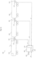
- Figure 1 shows a train 200, which is composed of a total of three rail vehicles 210, 220, 230.
- the first vehicle 210 is a traction vehicle, e.g. a locomotive.
- two coupling devices 247, 242 are provided, which connect the vehicles 210, 220, 230 to one another in a manner known per se.
- the coupling device 243 on the in Figure 1 right end of the vehicle 230 is not coupled with another counterpart of another vehicle, since the vehicle 230 is the last car (end car) of the train 200 according to Figure 1 forms.
- the coupling devices 241, 242, 243 3 can be automatic couplings which, in a manner known per se, also realize an electrical and/or pneumatic connection of the individual train parts 210, 220, 230 to one another in addition to a purely mechanical connection.
- sensor means 121, 122, 123 are provided which detect a coupling state of the respective coupling device 241, 242, 243.
- the sensor means 121, 122, 123 are designed as limit switches, i.e. as electromechanical sensor means, which experience an electrical state change when the operating state of the respective coupling device 241, 242, 243 changes from "uncoupled” to “coupled” or vice versa.
- the limit switches 121, 122, 123 can also be integrated directly into the coupling devices 241, 242, 243, for example.
- a control device 100 which has an input interface 110 for receiving the coupling state signals S1, S2, S3, as supplied by the limit switches 121, 122, 123.
- the coupling state signals S1, S2, S3 are evaluated by the control device 100 in order to conclude that decoupling is desired or that decoupling is undesirable.
- control device 100 has a control unit 130 which is at least partially designed in one of the following technologies: discrete logic circuit using semiconductor components (e.g. CMOS circuits), relay circuit, microcontroller, digital signal processor, programmable logic component, application-specific integrated circuit.
- semiconductor components e.g. CMOS circuits
- relay circuit e.g., relay circuit
- microcontroller e.g., microcontroller
- digital signal processor e.g., digital signal processor, programmable logic component, application-specific integrated circuit.
- the control device 100 concludes that a vehicle 220 is being uncoupled if the coupling state signal S2 of the relevant coupling device 242 indicates an uncoupled state or a transition to this state and a decoupling release signal EF does not simultaneously indicate the presence of an actually desired decoupling process.
- the decoupling release signal EF provided according to the invention must indicate the presence of an actually desired decoupling process.
- a desired decoupling process must be signaled by means of a separate decoupling release signal EF.
- the decoupling release signal EF is preferably also fed to the control device 100 and also evaluated by this or its control unit 130.
- the uncoupling release signal EF is formed as a function of at least two different variables, in particular of different operating variables of the train 200 or individual vehicles 210, 220, 230.
- the uncoupling release signal EF is thus not only formed as a function of, for example, a standstill signal STS ( Figure 2a ) is formed.
- a standstill signal STS Figure 2a
- conventional methods in which only the standstill signal STS is evaluated, and in which, when the standstill signal STS indicates that the train 200 is at a standstill, no consideration is given to any signals that may be present that indicate a coupling state, there is a disadvantage in that there is no possibility of monitoring an undesired uncoupling when the train is at a standstill.
- the decoupling release signal EF is dependent on the standstill signal STS ( Figure 2a ) and the pressure PHLL in the main air line (not shown) of train 200 ( Figure 1 ).
- the main air line is a pneumatic system that runs through the entire train 200.
- a standard operating pressure for the main air line is usually 5 bar.
- the main air line is usually used to operate a safety braking system of the train 200.
- the brakes of the train 200 are released.
- the pressure PHLL is reduced - starting from the standard operating pressure - until the desired braking effect is achieved.
- the brakes are released again by increasing the pressure PHLL in the main air line up to the standard operating pressure.
- the inventive formation of the decoupling release signal EF depending on the standstill signal STS and the pressure PHLL in the main air line of the train 200 advantageously enables the creation of a particularly reliable criterion for displaying an actually desired uncoupling process.
- the uncoupling release signal EF according to the above definition is only present or only has a value of "logical one" (true) if, firstly, the standstill signal STS is also "logical one", i.e. the train 200 is either moving very slowly or is standing still, and secondly, if the defined pressure PHLL is present in the main air line of the train 200.
- This defined pressure is a specially predeterminable pressure or pressure range of or around, for example, 2.8 bar, which thus means a code to display the information that a desired uncoupling process is to take place.
- the targeted setting of this special pressure value or pressure range in the main air line is generally impossible for unauthorized persons and can usually only be initiated from a driver's console on train 200. This ensures that no unwanted manipulation by unauthorized persons or malfunctions lead to an uncoupling release signal EF being incorrectly signaled with the value "logical one".
- a valid uncoupling release signal EF can only be generated if the standstill signal STS is actually present or has a value of logical one, and if the predetermined pressure PHLL of the main air line has been initiated by deliberate action by the train driver or another authorized person. This means that in order to indicate an actually desired coupling process, the train 200 must first be transferred to an operating state in which the standstill signal STS has a value of logical 1, and furthermore the pressure PHLL in the main air line must be reduced or set to the predefined value.
- the initiation of the vehicle reaction by the control unit 100 can, for example, take place via an interface 140 to a driver's console and/or a vehicle bus and/or a control center.
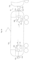
- Figure 1b shows a traction vehicle 210a according to a further, particularly preferred, embodiment of the invention.
- the traction vehicle 210a has on its Figure 1b left front side has a first coupling point 240a, which is currently not connected to a suitable coupling point of another vehicle (not shown).
- the traction vehicle 210a has on its Figure 1b right front side has a second coupling point 241a, which is connected to the matching coupling point 241b of another vehicle 220a.
- the second coupling point 241a forms with the coupling point 241b of the other vehicle 220a a coupling device 241 comparable to the system according to Figure 1a .
- the traction vehicle 210a has a total of two control units 100a, 100b, the functionality and structure of which essentially correspond to that of the control unit 100 from Figure 1a
- the first control unit 100a is assigned to the first coupling point 240a
- the second control unit 100b is assigned to the second coupling point 241a.
- the first coupling point 240a is also assigned the sensor means 120a (again, e.g. limit switches), which generate a coupling state signal or coupling point state signal characterizing the operating state of the coupling point 240a and feed it to the control unit 100a.
- the control unit 100b receives a comparable coupling state signal or coupling point state signal characterizing the operating state of the coupling point 241a from the sensor means 121a, which are also arranged in the area of their assigned coupling point 241a or are integrated therein.
- Each control unit 100a, 100b operates autonomously, i.e. independently of other similar control units 100b, 100a of the traction vehicle and is designed to execute of the method according to the invention.
- the control unit 100a, 100b according to Figure 1b a "single-channel" system compared to the variant according to Figure 1a , because the control unit 100a, 100b only monitors one coupling point 240a, 241a assigned to it.
- This "single-channel" variant is particularly preferred because it does not require any vehicle-wide signal connections, as may be the case with the system according to Figure 1a is the case.
- Figure 1b shows a traction vehicle 210a which has two independent monitoring systems according to the invention for a coupling state, wherein the components 100a, 120a form the first system, and wherein the components 100b, 121a form the second system.
- the coupling device 241 comprising both interacting coupling points 241a, 241b would advantageously be monitored simultaneously by two systems according to the invention, namely one for each coupling point 241a, 241b.
- train 200 would be Figure 1a - instead of the "three-channel" system shown - have a maximum of six monitoring systems in total, namely five for the Figure 1a illustrated coupling points of the coupling devices 241, 242, 243 and a sixth system for the Figure 1a second coupling point of traction vehicle 210 (not shown).
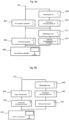
- Figure 2a shows a first logic diagram for forming the decoupling release signal EF according to the invention in accordance with a first embodiment.
- a first input variable is formed by the standstill signal STS, which is present in the train 200 in a manner known per se only when the train 200 has a speed that is less than or equal to a predeterminable threshold of, for example, approximately 1 or 2 km/h.
- the second input signal represents a pressure PHLL in a main air line of the train 200.
- the evaluation block 180 it is checked whether the standstill signal STS has a value of logical one, and whether at the same time the pressure PHLL in the main air line is in a predeterminable pressure range (for example between approximately 2.5 bar and approximately 2.8 bar) or pressure value.
- the evaluation block 180 outputs the decoupling release signal EF according to the invention with a value of logical one at its output 181 in order to inform the control device 100 ( Figure 1 ) to indicate that a desired uncoupling process is imminent. If one of the two criteria for the input variables STS, PHLL is not met, the output variable EF has a value of logical zero, so that the control device 100 triggers a corresponding vehicle reaction when uncoupling in the area of the coupling devices 241, 242 is detected by the signals S1, S2.
- the functionality of the evaluation block 180 is preferably implemented in the control unit 130 of the control device 100. The same applies to the evaluation block 182 described below.
- Figure 2b shows a further embodiment for determining the decoupling release signal EF according to the invention.
- the standstill signal STS is again fed to the input of the evaluation device 182.
- a modulation signal Mod is provided as a second input variable for the evaluation block 182.
- the modulation signal Mod is a signal that can be triggered, for example, by an authorized person in the area of one of the vehicles 210, 220, 230 and/or the corresponding coupling device 241, 242, 243, for example by modulating a corresponding supply voltage of an electrical supply line running through the entire train 200 (not shown). Similar signaling can also be carried out by means of a known RFID transponder system or the like.
- Wireless signaling of the modulation signal Mod directly to the control device 100 is also conceivable, for example by means of a short-range radio connection (WLAN, Bluetooth, ZigBee) or the like.
- WLAN wireless local area network
- Bluetooth ZigBee
- Cellular communication networks GSM, UMTS, LTE
- GSM Global System for Mobile communications
- a decoupling release signal EF with a truth value of logical one is only output at an output 183 of the evaluation block 182 if the standstill signal STS has a value of logical one, thus the standstill condition is fulfilled, and if at the same time the modulation signal Mod indicates that an authorized person is signaling a desired impending decoupling process.
- This can be done, for example, using a predefinable modulation scheme.
- the control device 100 concludes, by evaluating the signal EF of the evaluation unit 182, that a desired decoupling process is taking place and does not trigger any vehicle reactions as are provided for in the event of an undesired decoupling process.
- the uncoupling release signal EF depends on at least two operating variables of the train 200 ( Figure 1a ) and/or at least one vehicle 210, in particular depending on a) a signal from an input device operable by an operator and b) a pressure PHLL in a main air line of the train 200.
- the standstill signal STS is therefore not necessarily used to form the decoupling release signal EF according to the invention.
- the signal from an input device that can be operated by an operator can be, for example, an output signal from a key switch 502a ( Figure 5 ) which can also be integrated into an existing system of the vehicle 210, such as a driver's console or a control cabinet.
- the input device can also be designed as a conventional switch (without a key) or as another input system 502a, e.g. as an RFID input system or the like.
- the second criterion used is again the air pressure PHLL in a main air line of the train 200 or vehicle 210, which is shown in the flow chart according to Figure 5 for example, by means of the pressure switch 502b in a manner known to those skilled in the art, it is determined and evaluated and can be linked to the signal of the switch 502a in order to form the decoupling release signal EF according to the invention, which is present at the output of the evaluation block 502 for forwarding to the evaluation block 504, which in turn is implemented, for example, in the control device 100, e.g. as a logic circuit in the control unit 130.
- the function block 506 which is subordinate to the evaluation block 504, serves to control the decoupling valves 506b, for example in those operating cases in which the previous evaluation of the relevant clutch status signal s1 and the decoupling release signal EF has shown that a desired decoupling should be carried out. Then, according to Figure 5 Block 506a checks whether the standstill signal STS is present, and if this is the case, two control branches 506b for redundant decoupling valves 1, 2 are activated to carry out the decoupling.
- the standstill signal STS is therefore not used to form the uncoupling release signal EF, but the standstill condition is only checked by block 506a when the uncoupling is to take place.
- the standstill condition STS could also be checked directly in the evaluation block 502, ie in addition to the two other criteria 502a, 502b.
- Figure 3 shows a flow chart of an embodiment of a method according to the invention.
- a first step 300 the clutch state signals S1, S2, S3 ( Figure 1 ) is evaluated.
- the second step 310 the presence of the decoupling release signal EF according to the invention is checked, for example by means of the method described above with reference to the Figures 2a, 2b described logic circuits.
- step 320 an evaluation is carried out as to whether, when a clutch state change is detected, at least one of the clutch state signals S1, S2, S3 simultaneously has the decoupling release signal EF present, and if necessary, a corresponding vehicle reaction is initiated.
- the procedure according to Figure 3 can preferably run permanently during operation of the train 200 or only in predeterminable operating situations or times.
- An appropriate supply of electrical energy to the control device 100 and the supply of the signals S1, S2, S3, STS, PHLL, Mod must be ensured for the desired operating cases.
- the supply of the signals S1, S2, S3, STS, PHLL, Mod can either take place via separate channels or lines, or at least partially via the interface 140 to other on-board systems of the train 200.
- the control device 100a is accordingly to be supplied with the sensor signal indicating a coupling point state, e.g. from the sensor 120a, as well as with the signal EF, which is formed, e.g., by an external logic integrated into an existing control cabinet of the vehicle 210.
- a logic like the control device 100a, can also be integrated directly into a driver's console or a control panel supplementing the driver's console.
- the logic 502 forming the signal EF ( Figure 5 ) must be connected to the required input signals 502a, 502b and if necessary 506a or STS ( Figure 2a ) are supplied.
- FIG 4a shows a logic diagram of a further embodiment of the invention, which explains the monitoring of a coupling device 241 according to the invention.
- the connection 401 corresponds to a vehicle voltage connection of the train 200.
- the subordinate function block 408 it is checked whether the standstill signal STS ( Figure 2a, 2b ) is active, thus indicating that the train 200 is at a standstill. If this is the case, the system branches to the subordinate block 410, where it is checked whether a driver's console of the train 200 or the railcar 210 ( Figure 1 ) has been activated for a defined time interval. If this is the case, a branch is made to function block 404, which checks whether the coupling device 241 is mechanically coupled.
- function block 404 corresponds to a check or evaluation of the coupling state signal S1 by the control unit 100. If the criterion of function block 404 is also met, a branch is made to function block 406, in which a "no train break" flag is signaled or set for the coupling device 241.
- the function blocks 408, 410, 404 explained above correspond to an initialization path as it is run through during initialization after the control device 100 according to the invention is switched on. The "no train break" flag indicates that no undesired uncoupling has been detected since then within the scope of the inventive monitoring of the operating state of the coupling device 241.
- function block 402 checks whether there is no break in the coupling device 241. If this is the case, the system branches to function block 404 and finally to 406.
- the other function blocks 412, 414 check whether the standstill signal is active and then whether a defined main line pressure for uncoupling is present (block 414).
- the function blocks 412, 414 correspond to a function branch that is run through when an authorized person takes all measures to prepare for a desired uncoupling, namely to signal the uncoupling release signal EF.
- the function blocks 412, 414 check the criteria (STS, PHLL) required for the output of the uncoupling release signal EF with a value of logical one and then branch again to the function block 406, which sets the status flag "no train break" of the coupling device 241.
- a comparable logic structure can be provided for the further coupling devices 242, 243 of the train 200 and the control device 100.
- Figure 4b gives a block diagram that describes a detection of the end car 230.
- An initialization branch is given by the function blocks 422, 424, whereby the function block 422, which checks whether the car 230 is not coupled, is in turn connected to a vehicle voltage or a vehicle voltage connection 421. If the car 230 is not coupled, i.e. its coupling device 243 is not connected to a corresponding coupling device of another, following car (not shown), a check is made in the function block 424 as to whether the driver's console has been activated for a defined time interval. If this is not the case, a branch is made to block 426, in which it is concluded that the car 230 is not coupled, and therefore represents an end car 230.
- the branch formed by the function blocks 428, 430, 432 successively checks whether the standstill signal STS ( Figure 2a, 2b ) is active (block 428), whether the driver's console is activated for a defined time interval (block 430), and whether the car 230 is mechanically coupled (block 432). Only when these criteria are met does the system branch to block 426.
- the two branches according to Figure 4b are equally used to determine whether the car 230 is an end car, compare block 426.
- Figure 4c shows a logic diagram which illustrates the signal flow as it is used in a further embodiment to set the "no train break" flag.
- this flag is preferably always set after an initialization of the control device 100 when all limit switches of the sensor means 121, 122, 123 have been checked and no uncoupled state has been detected.
- the flag is preferably stored over the entire operating period of the control device 100.
- connection 441 is in turn connected to a vehicle voltage connection of the train 200.
- block 442 it is determined whether a carriage is not coupled, which corresponds, for example, to the evaluation of the limit switch 121 by the control device 100.
- the flag "no train break" is set.
- a safety loop is closed in blocks 448 or no emergency brake is set, so that no safety braking is triggered.
- the train end signals are controlled in a predefined manner.
- the block 450 is in turn connected to a vehicle voltage connection 441'.
- function block 442 it is also possible to branch to block 444 via the function block 446, which checks whether there is no train break at a coupling point, in which the flag "no train break" is set.
- Function block 442 is successfully completed if the logic structure defined by Figure 4c The checked car is an end car 230, while the function block 446 according to Figure 4c is successfully completed if the checked car is not the end car 230 and at the same time there is no train break at the coupling device 241.
- the logic structures according to the above with reference to the Figures 4a, 4b , 4c are advantageously also implemented in the control device 100, in particular in the control unit 130. They can preferably be implemented as relay circuits or in the form of a program for a microcontroller and/or a digital signal processor (DSP).
- DSP digital signal processor
- EPGA programmable logic components
- CPLD CPLD
- ASIC application-specific integrated circuits
- the embodiments described above advantageously make it possible to detect an unwanted train separation, which is also possible regardless of speed, especially when the train is at a standstill. Reliable detection can also be carried out for different configurations of the train 200.
- the following operating states are covered: normal operation (with existing control technology), restricted operation (control via train control lines without control technology), towing operation with active vehicle parts.
- the coupling states "mechanically coupled” or “mechanically not coupled” are automatically detected by means of the coupling state signals S1, S2, S3 and the sensor means 121, 122, 123 (for example limit switches), and a Flag "no train break" is set or initialized.
- the flag can be implemented, for example, in a hard-wired circuit by a relay. If a coupling state changes at the uncoupled coupling point 243 of the end car 230, this has no influence on the train break detection according to the invention according to a preferred embodiment.
- the signalling of an intentional train separation is advantageously carried out using the dedicated uncoupling release signal EF, which in turn can depend on various criteria (STS, PHLL, MOD).
- the following technical implementation is achieved in detail: if a driver's console is activated in the train 200/train formation, for example in a power car 210, then the status of each coupling device 241, 242, 243 in the train formation 200 is queried over a short time interval and stored in the control device 100, for example using the "no train break" flag. The monitoring according to the invention remains active until a driver's console is activated again.
- the state of a coupling device 241, 242 changes from “coupled” to "uncoupled” due to an unintentional train separation/unintentional uncoupling
- the "no train break" flag is deleted via the control device 100 and one or more of the vehicle reactions described several times above are triggered.
- the vehicle reactions can, for example, be the interruption of a safety/emergency braking loop in the still leading train part 210 and in the separated train part 220, 230.
- the other vehicle reactions, which are preferably also carried out, are described above.
- the current requirements for the vehicle reaction of train 200 can also be met, particularly in the event of an unintentional train separation, as set out in the supplementary regulations no. B015 "Protection goals derived from Section 4 AEG and EBO for coupling vehicles with automatic coupling when stationary" (Internet: WWW.EBA.BUND.DE Home page > Infothek > Vehicles > Brakes).
- the decoupling release signal EF is generated as follows: in order to signal a regular decoupling by means of the decoupling release signal EF according to the invention, the main air line is lowered from a control pressure to a defined value of, for example, 2.8 bar, and with the additional presence of the standstill signal STS, a decoupling process (for example with a key switch or decoupling cable) can be carried out without this being detected as a train break, because the control device 100 has been successfully informed via the decoupling release signal EF according to the invention that a desired decoupling process will be carried out.
- a decoupling process for example with a key switch or decoupling cable
- the circuit or control device 100 can only be reset by deactivating and reactivating a driver's console (if necessary combined with a renewed confirmation of the now changed train configuration) in the train 200/train section.
- the control device 100 is preferably equipped with the communication interface 140 for communication with the driver's console of the railcar 210 or another vehicle, but can also have further or several interfaces to other systems.
- the darkening of the end-of-train signals can only be cancelled by the train driver/conductor operating a special control element, but the "train break" event must first be acknowledged by the train driver, for example by making a corresponding entry in a human-machine interface provided for this purpose on the control device 100, such as a key switch or a graphical user interface.
- a human-machine interface provided for this purpose on the control device 100, such as a key switch or a graphical user interface.
Landscapes
- Engineering & Computer Science (AREA)
- Mechanical Engineering (AREA)
- Health & Medical Sciences (AREA)
- Biomedical Technology (AREA)
- General Health & Medical Sciences (AREA)
- Electric Propulsion And Braking For Vehicles (AREA)
- Arrangement And Mounting Of Devices That Control Transmission Of Motive Force (AREA)
- Train Traffic Observation, Control, And Security (AREA)
Description
- Die
DE 10 2008 034 018B3 offenbart ein Verfahren zum Ermitteln des Kupplungszustands einer UIC-Kupplung, eine UIC-Kupplung sowie eine Anordnung mit einer UIC-Kupplung. Die Erfindung betrifft ein Verfahren zur Überwachung eines Betriebszustands mindestens einer zur mechanischen Verbindung zweier Fahrzeuge zu einem Zug vorgesehenen Kupplungsvorrichtung und/oder Kupplungsstelle einer Kupplungsvorrichtung. - Die Erfindung betrifft ferner eine automatische Kupplungsvorrichtung mit einer Steuereinheit zur Überwachung eines Betriebszustands mindestens einer zur mechanischen Verbindung zweier Fahrzeuge zu einem Zug vorgesehenen Kupplungsvorrichtung und/oder Kupplungsstelle.
- Es ist Aufgabe der vorliegenden Erfindung, ein verbessertes Verfahren und eine verbesserte automatische Kupplungseinrichtung mit einer Steuereinrichtung anzugeben, die eine zuverlässig Erkennung eines unerwünschten Entkuppeln in allen Betriebszuständen eines Zugs, insbesondere auch während eines Stillstands bzw. einer Fahrt mit sehr niedriger Geschwindigkeit, ermöglichen. Diese Aufgabe wird bei dem Verfahren der eingangs genannten Art durch die Merkmale des Anspruches 1 gelöst. Die erfindungsgemäße Auswertung, die neben dem Kupplungszustandssignal auch noch das Entkupplungs-Freigabesignal berücksichtigt, ermöglicht vorteilhaft, eine universelle Überwachung der Kupplungsvorrichtung mittels Berücksichtigung des Kupplungszustandssignals vorzunehmen, während gleichzeitig durch die zusätzliche Berücksichtigung des Entkupplungs-Freigabesignals die Möglichkeit gegeben ist, ein tatsächlich gewünschtes Entkuppeln zu signalisieren, so dass in dem Falle eines gewünschten Entkuppelns nicht ebenfalls Fehlerreaktionen ausgelöst werden, wie sie möglicherweise für die Erkennung eines ungewünschten Entkuppelns vorgesehen sind.
- Das erfindungsgemäße Prinzip ist auf alle Fahrzeugverbände bzw. Züge anwendbar, die mittels mindestens einer Kupplungsvorrichtung aus einzelnen Fahrzeugen gebildet werden können, insbesondere auf Schienenfahrzeuge mit automatischen Kupplungsvorrichtungen. Besonders vorteilhaft ist der Einsatz der Erfindung bei selbsttätig indirekt bremsenden Fahrzeugen.
- Das Kupplungszustandssignal wird mittels einer entsprechenden Sensorik, die im Bereich der Kupplungsvorrichtung angebracht ist, gebildet. Erfindungsgemäß ist ein Endlagenschalter vorgesehen, der so an der Kupplungsvorrichtung angebracht ist, dass er eine Schaltzustandsänderung ausführt, wenn die Kupplungsvorrichtung von einem gekuppelten Zustand in einen entkuppelten Zustand überführt wird oder umgekehrt. Diese elektrische Schaltzustandsänderung kann erfindungsgemäß ausgewertet werden.
- Andere Sensormittel, beispielsweise kapazitive oder induktive oder optisch arbeitende Sensormittel sind alternativ oder ergänzend ebenfalls einsetzbar, um einen Kupplungszustand bzw. einen Zustandsübergang zu überwachen.
- Das Entkupplungs-Freigabesignal wird bei einer bevorzugten Ausführungsform der Erfindung, insbesondere bei Schienenfahrzeugen, vorteilhaft so definiert, dass es nicht oder nur schwer durch unberechtigte Personen beeinflusst werden kann, wodurch die Sabotagesicherheit des Überwachungsverfahrens bedeutend gesteigert wird. Beispielsweise ist es vorteilhaft, als Entkupplungs-Freigabesignal ein solches Signal zu wählen, welches nur unter erheblichem Aufwand von einem Außenbereich des Zugs bzw. sogar nur unter Verwendung eines Führerpults des Zugs bzw. eines Triebkopfes des Zugs beeinflussbar ist. Ein besonderer Vorteil der Erfindung ist es weiterhin, dass das Entkupplungs-Freigabesignal aus einer Kombination mehrerer Signale bzw. logischer Verknüpfungen gebildet wird, die ihrerseits aus weiteren Signalen oder Betriebsgrößen gebildet sind, wodurch eine noch zuverlässiger arbeitende Anordnung erhalten wird. Erfindungsgemäß ist vorgesehen, dass das Entkupplungs-Freigabesignal nicht allein in Abhängigkeit von einem eine Geschwindigkeit des Zugs und/oder mindestens eines der Fahrzeuge charakterisierenden Stillstandssignal gebildet wird. Das bedeutet, hierbei wird das Entkupplungs-Freigabesignal zwar unter Verwendung des Stillstandssignals gebildet, zusätzlich wird jedoch mindestens ein weiteres Signal des Zugs bzw. eines Fahrzeugs ausgewertet, um eine erhöhte Sicherheit zu bieten, die u.a. auch verschärften gesetzlichen Anforderungen bzw. Kriterienkatalogen von entsprechenden Zulassungsbehörden genügt. Dadurch ist eine gesteigerte Auswertungspräzision gegenüber bekannten Systemen geboten, bei denen lediglich das Stillstandssignal herangezogen wird, um zu entscheiden, ob ein ggf. auftretender Entkupplungsvorgang als zulässig oder unzulässig zu werten ist. Insbesondere hebt sich die Erfindung damit von solchen bekannten Verfahren ab, bei denen allein aufgrund des Vorliegens des Stillstandssignals bereits darauf geschlossen wird, dass möglicherweise auftretende Entkupplungsvorgänge zulässig sind. Diese Verfahren weisen nämlich u.a. den Nachteil auf, dass zum Beispiel ein unberechtigtes bzw. unerwünschtes Entkuppeln von Fahrzeugen aus einem Zug, der abfahrbereit auf dem Gleis steht, nicht erkannt werden kann, da die übergeordnete alleinige Auswertung des Stillstandssignals bewirkt, dass bei Vorliegen des Stillstandssignals jegliches Entkuppeln als zulässig gewertet wird.
- Auch das unberechtigte Bedienen einer Kupplungs-Notlöseeinrichtung an zur Abfahrt vorbereiteten Fahrzeugen kann durch das erfindungsgemäße Verfahren erkannt werden, weil eine wirksame Entkupplungs-Freigabe erst durch das erfindungsgemäße Entkupplungs-Freigabesignal angezeigt wird, das nicht allein in Abhangigkeit des Stillstandssignals sondern mindestens einer weiteren Größe gebildet wird. Solange zu dem erkannten Entkuppeln (Kupplungszustandssignal) nicht auch das erfindungsgemäße Entkupplungs-Freigabesignal vorliegt, kann erfindungsgemäß vorteilhaft stets auf ein unerwünschtes Entkuppeln geschlossen werden, insbesondere auch während das Stillstandssignal bereits einen Wert von logisch eins aufweist, der eine Stillstandsbedingung anzeigt.
- Daher sind unter Anwendung der erfindungsgemäßen Ausführungsformen vielfältige Fehlerzustände aufgrund unerwünschten Entkuppelns von Zugteilen erkennbar, insbesondere auch solche, bei denen ein unerwünschtes Entkuppeln während des Stillstands des Zugs stattfindet.
- Unter der Forderung, dass das Entkupplungs-Freigabesignal "gleichzeitig" zu dem Kupplungszustandssignal bzw. einer Kupplungszustandssignaländerung, die ein Entkuppeln anzeigt, vorliegen muss, wird vorliegend verstanden, dass das Entkupplungs-Freigabesignal in einem unmittelbaren zeitlichen Zusammenhang stehen muss zu einer eine Entkupplung anzeigenden Zustandsänderung des Kupplungszustandssignals. Besonders bevorzugt sind solche Ausführungsformen der Erfindung, bei denen das Entkupplungs-Freigabesignal als erstes vorliegen muss, d.h. noch bevor ein Zustand des Zustandkupplungssignals sich von "gekuppelt" nach "entkuppelt" ändert, um nicht eine Fahrzeugreaktion aufgrund unerwünschten Entkuppelns auszuschließen. Es ist jedoch auch denkbar, dass das Entkupplungsfreigabesignal i.w. gleichzeitig zu der Zustandsänderung des Kupplungszustandssignals (gegebenenfalls mit einer vorgebbaren Toleranzzeit, die von der Ausgestaltung einer das Verfahren ausführenden Steuereinheit abhängt) vorliegen muss, oder dass das Entkupplungs-Freigabesignal auch erst kurz nach dem einen entkuppelten Zustand anzeigenden Kupplungszustandssignal aktiviert sein kann um die Freigabe, mit in ein erwünschtes Entkuppeln, zu signalisieren.
- Bei dem Entkupplungs-Freigabesignal kann es sich beispielsweise um ein zweiwertiges (=binäres) Signal handeln, welches die Signalzustände "logisch null" und "logisch eins" aufweisen kann, wobei z.B. dem Signal zustand "logisch eins" das Vorliegen der erfindungsgemäßen Freigabebedingung für ein gewünschtes Entkuppeln zugeordnet wird. Dasselbe gilt für das an sich bekannte Stillstandssignal. Insoweit sind diese Signale in an sich bekannter Weise durch Logikschaltungen, z.B. diskrete Logikschaltungen aus Halbleiterbausteinen oder Relaisschaltungen, verarbeitbar bzw. erzeugbar.
- Bei einer vorteilhaften Ausführungsform ist vorgesehen, dass das Entkupplungs-Freigabesignal in Abhängigkeit des Stillstandssignals und eines Drucks in einer Hauptluftleitung des Zugs gebildet wird. Dadurch kann besonders vorteilhaft ein reguläres Entkuppeln von einem unerwünschten Entkuppeln angezeigt und unterschieden werden. Da das Entkupplungs-Freigabesignal bei dieser Ausführungsform unter anderem von dem Stillstandssignal abhängt, ist sichergestellt, dass ein erwünschtes Kuppeln stets nur dann signalisierbar ist bzw. erkannt wird, wenn das Stillstandssignal vorliegt, mithin der Zug eine sehr geringe Geschwindigkeit hat oder sich im Stillstand befindet. Das zusätzliche Kriterium des Drucks der Hauptluftleitung zur Bildung des Entkupplungsfreigabesignals stellt vorteilhaft ein besonders sicheres Kriterium gegenüber Manipulationen dar, weil unberechtigte Personen in der Regel nicht die Möglichkeit haben, den Druck in der Hauptluftleitung auf einen bestimmten Wert zu regulieren. Dies kann üblicherweise nur von dem Führerpult eines Fahrzeugs aus erfolgen. Beispielsweise kann das den Druck der Hauptluftleitung beschreibende Kriterium so ausgebildet sein, dass der Druck der Hauptluftleitung von einem Regeldruck (beispielsweise 5 bar) aus auf einen definierten, niedrigeren Wert (beispielsweise unter 3 bar z.B. zwischen 2,5 bar und 2,8 bar) abgesenkt werden muss, damit - unter gleichzeitigem Vorliegen des Stillstandssignals - das erfindungsgemäße Entkupplungsfreigabesignal einen Zustand von logisch 1 (wahr) annimmt, mithin anzeigt, dass ein gegebenenfalls erfolgender Entkupplungsvorgang ein gewünschter Entkupplungsvorgang ist. Durch die Vorgabe eines solch engen Druckbereichs zur Anzeige eines gewünschten Entkuppeln ist - neben der Manipulationssicherheit gleichzeitig auch sicher ausgeschlossen, dass das Entkupplungs-Freigabesignal sich zufällig (z.B. aufgrund von Störungen) auf den einen gewünschten Entkuppelvorgang anzeigenden Wert ändert. Erfindungsgemäß ist vorgesehen, dass das Entkupplungs-Freigabesignal in Abhängigkeit des Stillstandssignals und mindestens eines weiteren Signals gebildet wird, das eine Betriebsgröße des Zugs und/oder mindestens eines Fahrzeugs charakterisiert. Alternativ zu der Verwendung des Drucks der Hauptluftleitung kann beispielsweise definiert sein, dass eine - analog zu der Hauptluftleitung - ebenfalls im gesamten Zug vorliegende Niederspannungsleitung zur Versorgung von elektrischen Verbrauchern der einzelnen Fahrzeuge in einer definierten Weise beeinflusst wird, beispielsweise durch eine Modulation mit einem hochfrequenten Signal, welches sich auf der gesamten elektrischen Versorgungsleitung ausbreitet und somit in jedem Fahrzeug des Zugs durch eine einfache Detektorschaltung nachweisbar ist. Erst wenn das Stillstandssignal von der erfindungsgemäßen Steuereinrichtung selektiert wird und zusätzlich das erfindungsgemäß definierte Modulationssignal auf der elektrischen Versorgungsleitung detektiert wird, wird dann davon ausgegangen, dass ein gewünschter Entkupplungsvorgang eingeleitet wird. Alternativ oder ergänzend kann das erfindungsgemäße Kriterium des Entkupplungs-Freigabesignals auch weitere Signale umfassen, die beispielsweise auch mittel RFID-Identifikationsgebern und entsprechenden Empfängern im Bereich des Zugs realisiert sein können. In diesem Fall kann die Steuereinrichtung beispielsweise prüfen, ob das Stillstandssignal vorliegt und ob gleichzeitig ein bestimmter, berechtigter RFID-Identifikationsgeber mit der Leseelektronik des Zugs verbunden worden ist, um ein berechtigtes Entkuppeln anzuzeigen. In allen anderen Fällen kann wiederum eine Fahrzeugreaktion ausgelöst werden, weil auf ein unerwünschtes Entkuppeln geschlossen worden ist.
- Alternativ oder ergänzend kann einer weiteren Ausführungsform zufolge vorgesehen sein, dass das Entkupplungs-Freigabesignal in Abhängigkeit von mindestens zwei Betriebsgrößen des Zugs und/oder mindestens eines Fahrzeugs gebildet wird, insbesondere in Abhängigkeit von a) einem Signal einer durch eine Bedienperson betätigbaren Eingabeeinrichtung und b) einem Druck in einer Hauptluftleitung des Zugs. Bei dieser Variante wird demnach nicht das Stillstandssignal herangezogen, um das erfindungsgemäße Entkupplungs-Freigabesignal zu bilden. Vielmehr kann es sich bei dem Signal einer durch eine Bedienperson betätigbaren Eingabeeinrichtung beispielsweise um ein Ausgangssignal eines Schlüsselschalters handeln, der z.B. auch in ein bestehendes System des Fahrzeugs wie z.B. in ein Führerpult oder einen Schaltschrank integrierbar ist. Die Eingabeeinrichtung kann auch als herkömnlicher Schalter (ohne Schlüssel) oder als sonstiges Eingabesystem ausgebildet sein, z.B. als RFID-Eingabesystem oder dergleichen. Als zweites Kriterium wird wiederum der Luftdruck in einer Hauptluftleitung des Zugs bzw. Fahrzeugs verwendet, der beispielsweise mittels eines Druckschalters in dem Fachmann bekannter Weise auswertbar und mit dem Signal des Schalters verknüpfbar ist, um das erfindungsgemäße Entkupplungs-Freigabesignal zu bilden.
- Bei einer weiteren besonders vorteilhaften Ausführungsform kann auch vorgesehen sein, im Zusammenhang mit der Erzeugung des Entkupplungs-Freigabesignals eine Information über die betreffende Kupplungsstelle bzw. Kupplungsvorrichtung, die entkuppelt werden soll, an die Steuereinrichtung abzugeben, um eine noch präzisere Überwachung des Betriebszustands zu ermöglichen.
- Bei einer weiteren vorteilhaften Ausführungsform ist vorgesehen, dass die Fahrzeugreaktion bei unerwünschtem Entkuppeln mindestens einen der folgenden Schritte aufweist:
- Unterbrechung einer Sicherheits-/Schnellbremsschleife in einem noch führenden und/oder in dem abgetrennten Zugteil,
- Deaktivierung eines Zugschlusslichtsignals an der ehemaligen Kuppelstelle (insbesondere gemäß Ril 408 DB Netz AG),
- Anstoßen entsprechender Leittechnikmeldungen, insbesondere in einem Normalbetrieb,
- Aufhebung der bestätigten Zugkonfiguration, insbesondere in allen Betriebsmodi,
- Setzen einer Hardwaretraktionssperre aufgrund des nun differierenden Kupplungszustands in jedem Zugteil.
- Bei einer weiteren besonders vorteilhaften Ausführungsform des erfindungsgemäßen Verfahrens ist vorgesehen, dass die Kupplungszustandssignale mehrerer Kupplungsvorrichtungen durch die Steuereinrichtung ausgewertet werden. Besonders vorteilhaft werden bei einem aus mehreren, beispielsweise drei, Fahrzeugen zusammengestellten Zug alle drei Kupplungsvorrichtungen der entsprechenden Fahrzeuge erfindungsgemäß überwacht, wenigstens jedoch die beiden Kupplungsvorrichtungen, die das erste und das zweite Fahrzeug und das zweite und das dritte Fahrzeug miteinander verbinden.
- Bei einer weiteren bevorzugten Ausführungsform wird ein Kupplungszustandssignal einer einzigen Kupplungsstelle einer Kupplungsvorrichtung durch die Steuereinrichtung ausgewertet.
- Als eine weitere Lösung der Aufgabe der vorliegenden Erfindung ist eine automatische Kupplungsvorrichtung mit einer Steuereinrichtung gemäß Patentanspruch 8 angegeben.
- Vorteilhafte Ausführungsformen sind Gegenstand der Unteransprüche.
- Weitere Vorteile, Merkmale und Einzelheiten der Erfindung sind in der nachfolgenden Figurenbeschreibung unter Bezugnahme auf die Zeichnung angegeben. In der Zeichnung zeigt:
- Figur 1a
- ein Szenario zur Anwendung des erfindungsgemäßen Verfahrens gemäß einer ersten Ausführungsform,
- Figur 1b
- ein Szenario zur Anwendung des erfindungsgemäßen Verfahrens gemäß einer zweiten Ausführungsform,
- Figur 2a, 2b
- Logikdiagramme zweier Ausführungsformen des erfindungsgemäßen Verfahrens,
- Figur 3 ein
- Flussdiagramm einer Ausführungsform des erfindungsgemäßen Verfahrens,
- Figur 4a, 4b, 4c
- Ablaufdiagramme weiterer Ausführungsformen, und
- Figur 5
- ein Flussdiagramm einer weiteren Ausführungsform.
-
Figur 1 zeigt einen Zug 200, der aus insgesamt drei Schienenfahrzeugen 210, 220, 230 zusammengestellt ist. Bei dem ersten Fahrzeug 210 handelt es sich um ein Triebfahrzeug, z.B. um eine Lokomotive. Zwischen den Fahrzeugen 210, 220, 230 sind zwei Kupplungseinrichtungen 247, 242 vorgesehen, die die Fahrzeuge 210, 220, 230 in an sich bekannter Weise miteinander verbinden. Die Kupplungseinrichtung 243 an dem inFigur 1 rechts abgebildeten Ende des Fahrzeugs 230 ist nicht mit einem weiteren Gegenstück eines anderen Fahrzeugs gekuppelt, da das Fahrzeug 230 den letzten Wagen (Endwagen) des Zugs 200 gemäßFigur 1 bildet. - Bei den Kupplungseinrichtungen 241, 242, 243 3 kann es sich um automatische Kupplungen handeln, die ferner in an sich bekannter Weise neben einer rein mechanischen Verbindung ggf. auch noch eine elektrische und/oder pneumatische Verbindung der einzelnen Zugteile 210, 220, 230 untereinander realisiert.
- Erfindungsgemäß sind Sensormittel 121, 122, 123 vorgesehen, die einen Kupplungszustand der jeweiligen Kupplungsvorrichtung 241, 242, 243 erkennen. Vorliegend sind die Sensormittel 121, 122, 123 als Endlagenschalter, also als elektromechanische Sensormittel, ausgebildet, die eine elektrische Zustandsänderung erfahren, wenn sich der Betriebszustand der betreffenden Kupplungsvorrichtung 241, 242, 243 von "entkuppelt" nach "eingekuppelt" oder umgekehrt ändert. Die Endlagenschalter 121, 122, 123 können z.B. auch direkt in die Kupplungsvorrichtungen 241, 242, 243 integriert sein.
- Erfindungsgemäß ist eine Steuereinrichtung 100 vorgesehen, die eine Eingangsschnittstelle 110 zum Empfang der Kupplungszustandssignale S1, S2, S3, wie sie durch die Endlagenschalter 121, 122, 123 geliefert werden, aufweist. Erfindungsgemäß wenn die Kupplungszustandssignale S1, S2, S3 durch die Steuereinrichtung 100 ausgewertet, um auf ein erwünschtes Entkuppeln bzw. ein unerwünschtes Entkuppeln zu schließen.
- Hierzu verfügt die Steuereinrichtung 100 über eine Steuereinheit 130, die zumindest teilweise in einer der folgenden Technologien ausgebildet ist: diskrete hogikschaltung unter Verwendung von Halbleiterbausteinen (z.B. CMOS-Schaltungen), Relaisschaltung, Mikrokontroller, digitaler Signalprozessor, programmierbarer Logikbaustein, anwendungsspezifische integrierte Schaltung.
- Erfindungsgemäß ist vorgesehen, dass die Steuereinrichtung 100 dann auf ein unerwünschtes Entkuppeln eines Fahrzeugs 220 schließt, wenn das Kupplungszustandssignal S2 der betreffenden Kupplungsvorrichtung 242 einen entkuppelten Zustand bzw. einen Übergang in diesen Zustand anzeigt und nicht gleichzeitig ein Entkupplungs-Freigabesignal EF das Vorliegen eines tatsächlich gewünschten Entkupplungsvorgangs anzeigt. D.h., um nicht auf ein unerwünschtes Entkuppeln zu schließen, wie es z.B. durch Manipulation durch unberechtigte Dritte oder Störungen auftreten kann, muss das erfindungsgemäß vorgesehene Entkupplungs-Freigabesignal EF das Vorliegen eines tatsächlich gewünschten Entkupplungsvorgangs anzeigen.
- Dadurch ist vorteilhaft sichergestellt, dass jede denkbare Manipulation an den Kupplungsvorrichtungen 241, 242, 243, die eine Änderung des Schaltzustands der Endlagenschalter 121, 122, 123 auslöst, durch die Steuereinrichtung 100 erkennbar ist. Um dennoch ein erwünschtes Entkuppeln durchführen zu können, ohne dabei Fehlerreaktionen auszulösen, wie sie für den Fall eines unerwünschten Entkuppelns vorgesehen und später näher beschrieben sind, ist erfindungsgemäß vorteilhaft vorgesehen, dass ein gewünschter Entkupplungsvorgang mittels eines gesonderten Entkupplungs-Freigabesignals EF signalisiert werden muss. Das Entkupplungs-Freigabesignal EF wird vorzugsweise ebenfalls der Steuereinrichtung 100 zugeführt und ebenfalls durch diese bzw. ihre Steuereinheit 130 ausgewertet.
- Wenn also ein gewünschter Entkupplungsvorgang bei den Kupplungsvorrichtungen 241 oder 242 des Zugs 200 durchgeführt werden soll, ist dafür Sorge zu tragen, dass das Entkupplungs-Freigabesignal EF der Steuereinheit 100 zugeführt wird. Erst dann führt eine Zustandsänderung eines Kupplungszustandssignals S1, S2 von einem gekuppelten Zustand zu einem entkuppelten Zustand nicht bereits zu dem Auslösen einer Fehlerreaktion bzw. einer Fahrzeugreaktion, die ein unerwünschtes Entkuppeln anzeigt.
- Bei einer besonders vorteilhaften Ausführungsform der Erfindung ist vorgesehen, dass das Entkupplungs-Freigabesignal EF in Abhängigkeit von mindestens zwei verschiedenen Größen, gebildet wird, insbesondere von unterschiedlichen Betriebsgrößen des Zugs 200 bzw. einzelner Fahrzeuge 210, 220, 230. Besonders vorteilhaft wird das Entkupplungs-Freigabesignal EF also nicht allein z.B. in Abhängigkeit von einem eine Geschwindigkeit des Zugs 200 und/oder mindestens eines der Fahrzeuge 210, 220, 230 charakterisierenden Stillstandssignal STS (
Figur 2a ) gebildet. Bei herkömmlichen Verfahren nämlich, bei denen allein das Stillstandsignal STS ausgewertet wird, und wobei dann, wenn das Stillstandssignal STS einen Stillstand des Zugs 200 anzeigt, keine Berücksichtigung von ggf. vorhandenen einen Kupplungszustand anzeigenden Signalen stattfindet, ist nämlich nachteilig keine Möglichkeit zur Überwachung einer unerwünschten Entkupplung in dem Stillstand des Zugs gegeben. - Dieser Nachteil wird erfindungsgemäß dadurch vermieden, dass bei einer besonders bevorzugten Variante das Entkupplungs-Freigabesignal EF in Abhängigkeit des Stillstandssignals STS (
Figur 2a ) und des Drucks PHLL in der Hauptluftleitung (nicht gezeigt) des Zugs 200 (Figur 1 ) gebildet wird. Bei der Hauptluftleitung handelt es sich um ein pneumatisches System, das durch den gesamten Zug 200 geführt ist. Ein Regelbetriebsdruck für die Hauptluftleitung liegt üblicherweise bei 5 bar. Die Hauptluftleitung wird üblicherweise dazu verwendet, ein Sicherheitsbremssystem des Zugs 200 zu betätigen. Bei dem Regelbetriebsdruck von 5,0 bar, der in dem Normalbetrieb des Zugs 200 aufrecht erhalten wird, sind die Bremsen des Zugs 200 gelöst. Zum Bremsen wird der Druck PHLL - ausgehend von dem Regelbetriebsdruck - verringert, bis die jeweils gewünschte Bremswirkung erreicht ist. Ein erneutes Lösen der Bremsen erfolgt wiederum durch eine Erhöhung des Drucks PHLL in der Hauptluftleitung bis zu dem Regelbetriebsdruck. - Die erfindungsgemäße Bildung des Entkupplungs-Freigabesignals EF in Abhängigkeit des Stillstandssignals STS und des Drucks PHLL in der Hauptluftleitung des Zugs 200 ermöglicht vorteilhaft die Schaffung eines besonders sicheren Kriteriums zur Anzeige eines tatsächlich gewünschten Entkupplungsvorgangs. Das Entkupplungs-Freigabesignal EF gemäß der vorstehenden Definition liegt nämlich nur dann vor, bzw. weist nur dann einen Wert von "logisch eins" (wahr) auf, wenn erstens das Stillstandssignal STS ebenfalls "logisch eins" ist, der Zug 200 also entweder nur sehr langsam fährt oder stillsteht, und wenn zweitens der definierte Druck PHLL in der Hauptluftleitung des Zugs 200 vorliegt. Bei diesem definieren Druck handelt es sich um einen speziell vorgebbaren Druck bzw. Druckbereich von bzw. um beispielsweise 2,8 bar, der mithin gleichsam eine Codierung zur Anzeige der Information bedeutet, dass ein gewünschter Entkupplungsvorgang stattfinden soll. Das gezielte Einstellen dieses besonderen Druckwerts bzw. Druckbereichs in der Hauptluftleitung ist in der Regel für unberechtigte Personen unmöglich und üblicherweise nur aus einem Führerpult des Zugs 200 heraus veranlassbar. Dadurch ist sichergestellt, dass keine unerwünschten Manipulationen durch Unberechtigte oder Störungen dazu führen, dass fälschlicherweise ein Entkupplungs-Freigabesignal EF mit dem Wert logisch eins" signalisiert wird.
- Vielmehr kann ein gültiges Entkupplungs-Freigabesignal EF nur dann erzeugt werden, wenn tatsächlich das Stillstandsignal STS vorliegt bzw. einen Wert von logisch eins aufweist, und wenn der vorbestimmte Druck PHLL der Hauptluftleitung durch bewusstes Handeln des Triebfahrzeugführers oder einer sonstigen autorisierten Person eingeleitet worden ist. Das bedeutet, um einen tatsächlich erwünschten Kupplungsvorgang anzuzeigen, muss der Zug 200 zunächst in einen Betriebszustand überführt werden, in dem das Stillstandsignal STS einen Wert von logisch 1 aufweist, und ferner muss der Druck PHLL in der Hauptluftleitung auf den vordefinierten Wert abgesenkt bzw. eingestellt werden. Dann liegt auch ein entsprechender Wert logisch eins des Entkupplungs-Freigabesignals EF vor, und es kann ein Entkupplungsvorgang bei einer der Kupplungsvorrichtungen 241, 242 eingeleitet werden, ohne dass die Steuereinrichtung 100 gleichzeitig auf einen unerwünschten Entkupplungsvorgang schließt.
- Sofern jedoch mindestens ein Kupplungszustandssignal S1, S2 eine Zustandsänderung von "gekuppelt" nach "entkuppelt" signalisiert und nicht gleichzeitig oder in direktem zeitlichen Zusammenhang auch das Entkupplungs-Freigabesignal EF einen tatsächlich gewünschten Entkupplungsvorgang anzeigt, wird einer weiteren vorteilhaften Ausführungsform zufolge eine Fahrzeugreaktion eingeleitet, die mindestens einen der folgenden Schritte aufweist:
- Unterbrechung einer Sicherheits-/Schnellbremsschleife in einem noch führenden Zugteil 210 und/oder in dem abgetrennten Zugteil 220, 230,
- Deaktivierung eines Zugschlusslichtsignals an der ehemaligen Kuppelstelle, insbesondere gemäß Ril 408 DB Netz AG,
- Anstoßen entsprechender Leittechnikmeldungen, insbesondere in einem Normalbetrieb,
- Aufhebung der bestätigten Zugkonfiguration, insbesondere in allen Betriebsmodi,
- Setzen einer Hardwaretraktionssperre aufgrund des nun differierenden Kupplungszustands in jedem Zugteil.
- Die Einleitung der Fahrzeugreaktion durch die Steuereinheit 100 kann beispielsweise über eine Schnittstelle 140 zu einem Führerpult und/oder einem Fahrzeugbus und/oder einer Leitstelle erfolgen.
-
Figur 1b zeigt ein Triebfahrzeug 210a gemäß einer weiteren, besonders bevorzugten, Ausführungsform der Erfindung. Das Triebfahrzeug 210a weist an seiner inFigur 1b linken Stirnseite eine erste Kupplungsstelle 240a auf, die gegenwärtig nicht mit einer passenden Kupplungsstelle eines weiteren Fahrzeugs (nicht gezeigt) verbunden ist. Ferner weist das Triebfahrzeug 210a an seiner inFigur 1b rechten Stirnseite eine zweite Kupplungsstelle 241a auf, die mit der passenden Kupplungsstelle 241b eines weiteren Fahrzeugs 220a verbunden ist. Die zweite Kupplungsstelle 241a bildet mit der Kupplungsstelle 241b des weiteren Fahrzeugs 220a eine Kupplungsvorrichtung 241 vergleichbar zu dem System nachFigur 1a . - Im Unterschied zu der Ausführungsform nach
Figur 1a weist das Triebfahrzeug 210a insgesamt zwei Steuereinheiten 100a, 100b auf, deren Funktionalität und Struktur im wesentlichen derjenigen der Steuereinheit 100 ausFigur 1a entspricht. Die erste Steuereinheit 100a ist der ersten Kupplungsstelle 240a zugeordnet, und die zweite Steuereinheit 100b ist der zweiten Kupplungsstelle 241a zugeordnet. Dadurch ist vorteilhaft die Möglichkeit gegeben, beide Kupplungsstellen 240a, 241a unabhängig voneinander, nämlich jeweils durch eine autarke Steuereinheit 100a, 100b zu überwachen. - Der ersten Kupplungsstelle 240a sind ferner die Sensormittel 120a (wiederum z.B. Endlagenschalter) zugeordnet, die ein den Betriebszustand der Kupplungsstelle 240a charakterisierendes Kupplungszustandssignal bzw. Kupplungsstellenzustandssignal erzeugen und der Steuereinheit 100a zuführen. Die Steuereinheit 100b erhält ein vergleichbares den Betriebszustand der Kupplungsstelle 241a charakterisierendes Kupplungszustandssignal bzw. Kupplungsstellenzustandssignal von den Sensormittel 121a, die ebenfalls im Bereich ihrer zugeordneten Kupplungsstelle 241a angeordnet bzw. darin integriert sind.
- Jede Steuereinheit 100a, 100b arbeitet autark, d.h. unabhängig von anderen gleichartigen Steuereinheiten 100b, 100a des Triebfahrzeugs und ist zur Ausführung des erfindungsgemäßen Verfahrens ausgebildet. Insoweit bildet z.B. die Steuereinheit 100a, 100b gemäß
Figur 1b jeweils ein "einkanaliges" System gegenüber der Variante nachFigur 1a , weil die Steuereinheit 100a, 100b jeweils nur eine ihr zugeordnete Kupplungsstelle 240a, 241a überwacht. Diese "einkanalige" Variante ist besonders bevorzugt, da sie keinerlei fahrzeugübergreifende Signalverbindungen erfordert, wie es ggf. bei dem System nachFigur 1a der Fall ist.Figur 1b zeigt demnach vielmehr ein Triebfahrzeug 210a, das zwei voneinander unabhängige erfindungsgemäße Überwachungssysteme für einen Kupplungszustand aufweist, wobei die Komponenten 100a, 120a das erste System bilden, und wobei die Komponenten 100b, 121a das zweite System bilden. - Sofern beispielsweise das in
Figur 1b teilweise gezeigte weitere Fahrzeug 220a ebenfalls über ein erfindungsgemäßes Überwachungssystem (nicht gezeigt) verfügt, das den Kupplungszustand der dem Fahrzeug 220a zugeordneten Kupplungsstelle 241b überwacht, würde die beide miteinander zusammenwirkende Kupplungsstellen 241a, 241b umfassende Kupplungsvorrichtung 241 vorteilhaft gleichzeitig durch zwei erfindungsgemäße Systeme, nämlich für jede Kupplungsstelle 241a, 241b eines, überwacht. - Unter Verwendung solcher "einkanaliger" Überwachungssysteme würde der Zug 200 gemäß
Figur 1a - anstelle des abgebildeten "dreikanaligen" Systems - maximal insgesamt sechs Überwachungssysteme aufweisen, nämlich fünf Stück für die inFigur 1a abgebildeten Kupplungsstellen der Kupplungsvorrichtungen 241, 242, 243 und ein sechstes System für die inFigur 1a nicht abgebildete zweite Kupplungsstelle des Triebfahrzeugs 210. -
Figur 2a zeigt ein erstes Logikdiagramm zur Bildung des erfindungsgemäßen Entkupplungs-Freigabesignals EF gemäß einer ersten Ausführungsform. Eine erste Eingangsgröße ist durch das Stillstandssignal STS gebildet, das bei dem Zug 200 in an sich bekannter Weise nur dann vorliegt, wenn der Zug 200 eine Geschwindigkeit aufweist, die kleiner/gleich einer vorgebbaren Schwelle von z.B. etwa 1 oder 2 km/h ist. Das zweite Eingangssignal repräsentiert einen Druck PHLL in einer Hauptluftleitung des Zugs 200. In dem Auswertungsblock 180 wird geprüft, ob das Stillstandssignal STS einen Wert von logisch eins aufweist, und ob gleichzeitig der Druck PHLL in der Hauptluftleitung in einem vorgebbaren Druckbereich (beispielsweise zwischen etwa 2,5 bar und etwa 2,8 bar) bzw. Druckwert aufweist. Wenn dies der Fall ist, gibt der Auswertungsblock 180 an seinem Ausgang 181 das erfindungsgemäße Entkupplungs-Freigabesignal EF mit einem Wert von logisch eins aus, um der Steuereinrichtung 100 (Figur 1 ) anzuzeigen, dass ein gewünschter Entkupplungsvorgang bevorsteht. Sofern eines der beiden Kriterien für die Eingangsgrößen STS, PHLL nicht erfüllt ist, weist die Ausgangsgröße EF einen Wert von logisch null auf, so dass die Steuereinrichtung 100 bei der Erkennung eines Entkuppelns im Bereich der Kupplungseinrichtungen 241, 242 durch die Signale S1, S2 eine entsprechende Fahrzeugreaktion auslöst. - Die Funktionalität des Auswertungsblocks 180 ist bevorzugt in der Steuereinheit 130 der Steuereinrichtung 100 realisiert. Das gleiche gilt für den nachstehend beschriebenen Auswertungsblock 182.
-
Figur 2b zeigt eine weitere Ausführungsform zur Ermittlung des erfindungsgemäßen Entkupplungs-Freigabesignals EF. Der Auswerteeinrichtung 182 ist eingangsseitig wiederum das Stillstandssignal STS zugeführt. Anstelle des Drucksignals PHLL (Figur 2a ) ist gemäß der Ausführungsform nachFigur 2b jedoch ein Modulationssignal Mod als zweite Eingangsgröße für den Auswertungsblock 182 vorgesehen. Bei dem Modulationssignal Mod handelt es sich um ein Signal, das beispielsweise durch eine berechtigte Person im Bereich eines der Fahrzeuge 210, 220, 230 und/oder der entsprechenden Kupplungsvorrichtung 241, 242, 243 ausgelöst werden kann, beispielsweise durch Modulieren einer entsprechenden Versorgungsspannung einer durch den gesamten Zug 200 verlaufenden elektrischen Versorgungsleitung (nicht gezeigt). Eine ähnliche Signalisierung kann auch mittels eines an sich bekannten RFID-Transpondersystems oder dergleichen erfolgen. Ebenso ist eine drahtlose Signalisierung des Modulationssignals Mod direkt an die Steuereinrichtung 100 denkbar, beispielsweise mittels einer Kurzstrecken-Funkverbindung (WLAN, Bluetooth, ZigBee) oder dergleichen. Selbstverständlich können auch zellulare Kommunikationsnetzwerke (GSM, UMTS, LTE) zur Signalisierung des Modulationssignals Mod verwendet werden. - Bei der Ausführungsform gemäß
Figur 2b wird ein Entkupplungs-Freigabesignal EF mit einem Wahrheitswert von logisch eins einem Ausgang 183 des Auswertungsblocks 182 nur dann ausgegeben, wenn das Stillstandssignal STS einen Wert von logisch eins aufweist, mithin die Stillstandsbedingung erfüllt ist, und wenn gleichzeitig das Modulationssignal Mod anzeigt, das eine berechtigte Person einen gewünschten bevorstehenden Entkupplungsvorgang signalisiert. Dies kann beispielsweise durch ein vorgebbares Modulationsschema erfolgen. In diesem Fall schließt die Steuereinrichtung 100 unter Auswertung des Signals EF der Auswerteeinheit 182 darauf, dass ein gewünschter Entkupplungsvorgang vorliegt und löst keine Fahrzeugreaktionen aus, wie sie für den Fall eines unerwünschten Entkupplungsvorgangs vorgesehen sind. - Alternativ oder ergänzend zu der Berücksichtigung des Stillstandssignals STS nach
Figur 2a, 2b kann einer weiteren Ausführungsform zufolge vorgesehen sein, dass das Entkupplungs-Freigabesignal EF in Abhängigkeit von mindestens zwei Betriebsgrößen des Zugs 200 (Figur 1a ) und/oder mindestens eines Fahrzeugs 210 gebildet wird, insbesondere in Abhängigkeit von a) einem Signal einer durch eine Bedienperson betätigbaren Eingabeeinrichtung und b) einem Druck PHLL in einer Hauptluftleitung des Zugs 200. Bei dieser Variante wird demnach nicht notwendig das Stillstandssignal STS herangezogen, um das erfindungsgemäße Entkupplungs-Freigabesignal EF zu bilden. Vielmehr kann es sich bei dem Signal einer durch eine Bedienperson betätigbaren Eingabeeinrichtung beispielsweise um ein Ausgangssignal eines Schlüsselschalters 502a (Figur 5 ) handeln, der z.B. auch in ein bestehendes System des Fahrzeugs 210 wie z.B. in ein Führerpult oder einen Schaltschrank integrierbar ist. Die Eingabeeinrichtung kann auch als herkömmlicher Schalter (ohne Schlüssel) oder als sonstiges Eingabesystem 502a ausgebildet sein, z.B. als RFID-Eingabesystem oder dergleichen. Als zweites Kriterium wird wiederum der Luftdruck PHLL in einer Hauptluftleitung des Zugs 200 bzw. Fahrzeugs 210 verwendet, der in dem Ablaufdiagramm gemäßFigur 5 beispielsweise mittels des Druckschalter 502b in dem Fachmann bekannter Weise ermittelt und ausgewertet und mit dem Signal des Schalters 502a verknüpfbar ist, um das erfindungsgemäße Entkupplungs-Freigabesignal EF zu bilden, das an dem Ausgang des Auswertungsblocks 502 zur Weiterleitung an den Auswertungsblock 504 anliegt, der seinerseits beispielsweise in der Steuereinrichtung 100, z.B. als Logikschaltung in der Steuereinheit 130, realisiert ist. - Der dem Auswertungsblock 504 nachgeordnete Funktionsblock 506 dient der Ansteuerung von Entkupplungsventilen 506b z.B. in solchen Betriebsfällen, in denen die vorangehende Auswertung des betreffenden Kuppltzngszustandssignals s1 und des Entkupplungs-Freigabesignals EF ergeben hat, dass ein gewünschtes Entkuppeln vorgenommen werden soll. Dann wird gemäß
Figur 5 durch Block 506a überprüft, ob das Stillstandssignal STS vorliegt, und wenn dies der Fall ist, werden zwei Ansteuerzweige 506b für redundante Entkuppelventile 1, 2 aktiv geschaltet, um das Entkuppeln durchzuführen. - Bei der vorstehend beschriebenen Ausführungsform nach
Figur 5 wird demnach das Stillstandssignal STS nicht zur Bildung des Entkupplungs-Freigabesignals EF verwendet, sondern die Stillstandsbedingung wird erst dann durch Block 506a überprüft, wenn das Entkuppeln erfolgen soll. Alternativ oder ergänzend könnte die Stillstandsbedingung STS auch direkt in dem Auswertungsblock 502, d.h. zusätzlich zu den zwei anderen Kriterien 502a, 502b, abgeprüft werden. -
Figur 3 zeigt ein Flussdiagramm einer Ausführungsform eines erfindungsgemäßen Verfahrens. - In einem ersten Schritt 300 werden die Kupplungszustandssignale S1, S2, S3 (
Figur 1 ) ausgewertet. In dem zweiten Schritt 310 wird das Vorliegen des erfindungsgemäßen Entkupplungs-Freigabesignals EF geprüft, beispielsweise mittels der vorstehend unter Bezugnahme auf dieFiguren 2a, 2b beschriebenen Logikschaltungen. - In Schritt 320 wird schließlich eine Auswertung dahingehend vorgenommen, ob bei einer erkannten Kupplungszustandsänderung mindestens eines der Kupplungszustandsignale S1, S2, S3 gleichzeitig das Entkupplungs-Freigabesignal EF vorliegt, und es wird gegebenenfalls eine entsprechende Fahrzeugreaktion eingeleitet.
- Das Verfahren gemäß
Figur 3 kann bevorzugt permanent während des Betriebs des Zugs 200 ablaufen oder auch nur in vorgebbaren Betriebssituationen oder -zeiten. Eine entsprechende Versorgung der Steuereinrichtung 100 mit elektrischer Energie sowie die Zuleitung der Signale S1, S2, S3, STS, PHLL, Mod ist für die gewünschten Betriebsfälle sicherzustellen. Die Zuleitung der Signale S1, S2, S3, STS, PHLL, Mod kann entweder über separate Kanäle bzw. Leitungen erfolgen, oder zumindest teilweise auch über die Schnittstelle 140 zu weiteren Bordsystemen des Zugs 200. - Bei der "einkanaligen" Ausbildung der Steuereinrichtung 100a (
Figur 1b ) ist die Steuereinrichtung 100a dementsprechend mit dem einen Kupplungsstellenzustand angebenden Sensorsignal z.B. von dem Sensor 120a zu versorgen sowie mit dem Signal EF, das z.B. durch eine externe, in einen vorhandenen Schaltschrank des Fahrzeugs 210 integrierte Logik, gebildet wird. Solch eine Logik kann, ebenso wie die Steuereinrichtung 100a, auch direkt in ein Führerpult oder eine das Führerpult ergänzende Kontrolltafel integriert werden. Die das Signal EF bildende Logik 502 (Figur 5 ) muss mit den erforderlichen Eingangssignalen 502a, 502b und ggf. 506a bzw. STS (Figur 2a ) versorgt werden. -
Figur 4a zeigt ein Logikdiagramm einer weiteren Ausführungsform der Erfindung, das die erfindungsgemäße Überwachung einer Kupplungsvorrichtung 241 erläutert. Der Anschluss 401 entspricht einem Fahrzeugspannungsanschluss des Zugs 200. In dem nachgeordneten Funktionsblock 408 wird überprüft, ob das Stillstandssignal STS (Figur 2a, 2b ) aktiv ist, mithin der Stillstand des Zugs 200 angezeigt wird. Wenn dies der Fall ist, wird zu dem nachgeordneten Block 410 verzweigt, in dem geprüft wird, ob ein Führerpult des Zugs 200 bzw. des Triebwagens 210 (Figur 1 ) für ein definiertes Zeitintervall hinweg aktiviert gewesen ist. Wenn dies der Fall ist, wird zu dem Funktionsblock 404 verzweigt, der überprüft, ob die Kupplungsvorrichtung 241 mechanisch gekuppelt ist. Insoweit entspricht der Funktionsblock 404 einer Überprüfung bzw. Auswertung des Kupplungszustandssignals S1 durch die Steuereinheit 100. Sofern auch das Kriterium des Funktionsblocks 404 erfüllt ist, wird in den Funktionsblock 406 verzweigt, bei dem ein Flag "kein Zugabriss" für die Kupplungsvorrichtung 241 signalisiert bzw. gesetzt wird. Die vorstehend erläuterten Funktionsblöcke 408, 410, 404 entsprechen insoweit einem Initialisierungspfad, wie er bei einer Initialisierung nach einem Einschalten der erfindungsgemäßen Steuereinrichtung 100 durchlaufen wird. Das Flag "kein Zugabriss" gibt an, dass im Rahmen der erfindungsgemäßen Überwachung des Betriebszustands der Kupplungsvorrichtung 241 seither kein unerwünschtes Entkuppeln erkannt worden ist. - Parallel zu dem durch die Blöcke 408, 410 gebildeten Pfad wird durch den Funktionsblock 402 überprüft, ob kein Abriss an der Kupplungsvorrichtung 241 vorliegt. Wenn dies der Fall ist, wird wiederum zu Funktionsblock 404 und schließlich zu 406 verzweigt.
- Die weiteren Funktionsblöcke 412, 414 gemäß des Diagramms nach
Figur 4a überprüfen, ob das Stillstandssignal aktiv ist, und ob anschließend ein definierter Hauptleitungsdruck zum Entkuppeln vorliegt (Block 414). Insoweit entsprechen die Funktionsblöcke 412, 414 einem Funktionszweig, der dann durchlaufen wird, wenn durch eine berechtigte Person alle Maßnahmen getroffen werden, um ein gewünschtes Entkuppeln vorzubereiten, nämlich um das Entkupplungs-Freigabesignal EF zu signalisieren. Das bedeutet, die Funktionsblöcke 412, 414 überprüfen die für die Ausgabe des Entkupplungs-Freigabesignals EF mit einem Wert von logisch eins nötigen Kriterien (STS, PHLL) und verzweigen anschließend wiederum zu dem Funktionsblock 406, der das Zustandsflag "kein Zugabriss" der Kupplungsvorrichtung 241 setzt. - Eine vergleichbare Logikstruktur kann für die weiteren Kupplungsvorrichtungen 242, 243 des Zugs 200 und der Steuereinrichtung 100 vorgesehen sein.
-
Figur 4b gibt ein Blockdiagramm an, das eine Erkennung des Endwagens 230 beschreibt. Ein Initialisierungszweig ist durch die Funktionsblöcke 422, 424 gegeben, wobei der Funktionsblock 422, der überprüft, ob der Wagen 230 nicht gekuppelt ist, wiederum mit einer Fahrzeugspannung bzw. einem Fahrzeugspannungsanschluss 421 verbunden ist. Sofern der Wagen 230 nicht gekuppelt ist, also seine Kupplungsvorrichtung 243 nicht mit einer entsprechenden Kupplungsvorrichtung eines weiteren, nachfolgenden Wagens (nicht gezeigt) verbunden ist, wird in dem Funktionsblock 424 überprüft, ob das Führerpult für ein definiertes Zeitintervall aktiviert gewesen ist. Wenn dies nicht der Fall ist, so wird in den Block 426 verzweigt, in dem darauf geschlossen wird, dass der Wagen 230 nicht gekuppelt ist, mithin einen Endwagen 230 darstellt. - Der durch die Funktionsblöcke 428, 430, 432 gebildete Zweig überprüft sukzessive, ob das Stillstandssignal STS (
Figur 2a, 2b ) aktiv ist (Block 428), ob das Führerpult aktiviert ist für ein definiertes Zeitintervall (Block 430), und ob der Wagen 230 mechanisch gekuppelt ist (Block 432). Erst wenn diese Kriterien erfüllt sind, wird ebenfalls in den Block 426 verzweigt. - Die beiden Zweige gemäß
Figur 4b , von denen der erste die Blöcke 422, 424, und von denen der zweite die Blöcke 428, 430, 432 aufweist, dienen also gleichberechtigt der Feststellung, ob der Wagen 230 ein Endwagen ist, vergleiche Block 426. -
Figur 4c zeigt ein Logikdiagramm, welches den Signalfluss veranschaulicht, wie er bei einer weiteren Ausführungsform dazu verwendet wird, das Flag "kein Zugabriss" zu setzen. Dieses Flag wird der weiteren Ausführungsform des erfindungsgemäßen Verfahrens zufolge bevorzugt immer nach einer Initialisierung der Steuereinrichtung 100 gesetzt, wenn alle Endlagenschalter der Sensormittel 121, 122, 123 überprüft worden sind und kein entkuppelter Zustand festgestellt worden ist. Das Flag wird vorzugsweise über den gesamten Betriebszeitraum der Steuereinrichtung 100 gespeichert. - Der Anschluss 441 ist wiederum mit einem Fahrzeugspannungsanschluss des Zugs 200 verbunden. In Block 442 wird festgestellt, ob ein Wagen nicht gekuppelt ist, was beispielsweise der Auswertung des Endlagenschalters 121 durch die Steuereinrichtung 100 entspricht. In dem nachgeordneten Block 444 wird schließlich das Flag "kein Zugabriss" gesetzt. In Folge dieses Schritts wird in den Blöcken 448 eine Sicherheitsschleife geschlossen bzw. keine Schnellbremse gesetzt, so dass keine Sicherheitsbremsung ausgelöst wird. In dem Funktionsblock 450 werden die Zugschlusssignale in einer vordefinierten Weise angesteuert. Der Block 450 ist seinerseits mit einem Fahrzeugsspannungsanschluss 441' verbunden. Alternativ zu dem Funktionsblock 442 kann auch über den Funktionsblock 446, mit dem geprüft wird, ob kein Zugabriss an einer Kuppelstelle erfolgt, in den Block 444 verzweigt werden, in dem das Flag "kein Zugabriss" gesetzt wird. Der Funktionsblock 442 wird dann erfolgreich durchlaufen, wenn es sich bei dem durch die Logikstruktur gemäß
Figur 4c überprüften Wagen um einen Endwagen 230 handelt, während der Funktionsblock 446 gemäßFigur 4c dann erfolgreich durchlaufen wird, wenn es sich bei dem überprüften Wagen nicht um den Endwagen 230 handelt und gleichzeitig kein Zugabriss an der Kupplungsvorrichtung 241 vorliegt. - Die Logikstrukturen gemäß den vorstehend unter Bezugnahme auf die
Figuren 4a, 4b ,4c erläuterten Diagrammen sind vorteilhaft ebenfalls in der Steuereinrichtung 100 implementiert, insbesondere in der Steuereinheit 130. Sie können vorzugsweise als Relaisschaltungen oder aber in Form eines Programms für einen Mikrocontroller und/oder einen digitalen Signalprozessor (DSP) implementiert sein. Die Verwendung von programmierbaren Logikbausteinen (EPGA, CPLD), anwendungsspezifischen integrierten Schaltungen (ASIC) oder dergleichen ist ebenfalls denkbar. - Die vorstehend beschriebenen Ausführungsformen ermöglichen vorteilhaft, eine ungewollte Zugtrennung zu detektierten, was insbesondere auch geschwindigkeitsunabhängig, speziell auch im Stillstand, ermöglicht ist. Ebenso kann für unterschiedliche Konfigurationen des Zugs 200 eine zuverlässige Erkennung erfolgen. Die vorliegenden Betriebszustände werden abgedeckt: Normalbetrieb (mit vorhandener Leittechnik), eingeschränkter Betrieb (Steuerung über Zugsteuerleitungen ohne Leittechnik), Abschleppbetrieb mit aktiven Fahrzeugteilen.
- Bei einer weiteren bevorzugten Ausführungsform werden nach dem Einschalten des Fahrzeugs 210 bzw. des Fahrzeugverbandes 200 die Kupplungszustände "mechanisch gekuppelt" bzw. "mechanisch nicht gekuppelt" automatisch delektiert mittels der Kupplungszustandssignale S1, S2, S3 und der Sensormittel 121, 122, 123 (zum Beispiel Endlagenschalter), und es wird ein Flag "kein Zugabriss" gesetzt bzw. initialisiert. Das Flag kann beispielsweise in einer fest verdrahteten Schaltung durch ein Relais realisiert werden. Ändert sich ein Kupplungszustand an der nicht gekuppelten Kuppelstelle 243 des Endwagens 230, so hat dies einer bevorzugten Ausführungsform zufolge keinen Einfluss auf die erfindungsgemäße Zugabrisserkennung. Ändert sich jedoch der Zustand an einer gekuppelten Kuppelstelle, vergleiche die Kupplungsvorrichtungen 241, 242, so fällt das Relais "kein Zugabriss" ab, sofern nicht vorher oder gleichzeitig eine gewollte Zugtrennung signalisiert bzw. eingeleitet worden ist. In diesem Fall wird ein Zugabriss gemeldet oder sonstige Fahrzeugreaktionen ausgelöst.
- Die Signalisierung einer gewollten Zugtrennung erfolgt wie bereits vorstehend beschrieben vorteilhaft unter Verwendung des dedizierten Entkupplungs-Freigabesignals EF, das seinerseits von verschiedenen Kriterien (STS, PHLL, MOD) abhängen kann.
- Bei einer weiteren besonders bevorzugten Ausführungsform der Erfindung ergibt sich die folgende technische Umsetzung im Detail: wird ein Führerpult im Zug 200 /Zugverband aktiviert, beispielsweise in einem Triebkopf 210, dann wird über ein kurzes Zeitintervall der Zustand jeder Kupplungsvorrichtung 241, 242, 243 im Zugverband 200 abgefragt und in der Steuereinrichtung 100 abgespeichert, beispielsweise unter Verwendung des Flags "kein Zugabriss". Bis zu einer erneuten Aktivierung eines Führerpults bleibt die erfindungsgemäße Überwachung aktiv. Ändert sich nun - unabhängig von der Auslöseursache (zum Beispiel Ansteuerung Entkuppelventil/Notlösezeug etc.) - durch eine ungewollte Zugtrennung/ungewolltes Entkuppeln der Zustand einer Kupplungsvorrichtung 241, 242 von "gekuppelt" in "nicht gekuppelt", so wird über die Steuereinrichtung 100 das Flag "kein Zugabriss"" gelöscht und eine oder mehrere der vorstehend mehrfach beschriebenen Fahrzeugreaktionen ausgelöst. Bei den Fahrzeugreaktionen kann es sich beispielsweise um die Unterbrechung einer Sicherheits-/Schnellbremsschleife im noch führenden Zugteil 210 und im abgetrennten Zugteil 220, 230 handeln. Die weiteren Fahrzeugreaktionen, die bevorzugt ebenfalls ausgeführt werden, sind vorstehend beschrieben.
- Unter Anwendung des erfindungsgemäßen Prinzips ist es vorteilhaft möglich, geschwindigkeitsunabhängig für die verschiedenen Betriebsmodi des Zugs 200 eine ungewollte Zugtrennung/ungewolltes Entkuppeln der Kupplungsvorrichtung 241, 242 sicher zu delektieren und die geforderten Fahrzeugreaktionen hervorzurufen.
- Insbesondere können durch Anwendung des erfindungsgemäßen Prinzips auch die aktuellen Anforderungen an die Fahrzeugreaktion des Zugs 200 insbesondere für den Fall einer ungewollten Zugtrennung eingehalten werden, wie sie in den Ergänzungsregelungen Nr. B015 "aus § 4 AEG und EBO abgeleitete Schutzziele zum Kuppeln von Fahrzeugen mit automatischer Kupplung im Stand" (Internet: WWW.EBA.BUND.DE Startseite > Infothek > Fahrzeuge > Bremsen) dargelegt sind.
- Besonders vorteilhaft werden - im Unterschied zu herkömmlichen Systemen - nun auch im Stillstand des Zugs 200 ungewünschte Entkupplungsereignisse sicher erkannt.
- Bei einer weiteren besonders vorteilhaften Ausführungsform wird zur Erzeugung des Entkupplungs-Freigabesignals EF wie folgt vorgegangen: um ein reguläres Entkuppeln mittels des erfindungsgemäßen Entkupplungs-Freigabesignals EF zu signalisieren, wird die Hauptluftleitung von einem Regeldruck aus auf einen definierten Wert von beispielsweise 2,8 bar abgesenkt, und mit einem zusätzlichen Vorliegen des Stillstandssignals STS kann ein Entkupplungsvorgang (zum Beispiel mit Schlüsselschalter oder Entkupplungsseil) durchgeführt werden, ohne dass dieser als Zugabriss detektiert wird, weil die Steuereinrichtung 100 über das erfindungsgemäße Entkupplungs-Freigabesignal EF erfolgreich darüber informiert worden ist, dass ein erwünschter Entkupplungsvorgang durchgeführt werden wird.
- Umgekehrt wird bei den erfindungsgemäßen Ausführungsformen auch eine Manipulation an Kupplungsvorrichtungen (zum Beispiel ungewolltes Ansteuern der Entkuppelventile / unberechtigtes Bedienen der Kupplungs-Notlöseeinrichtung) an zur Abfahrt vorbereiteten Fahrzeugen 200 durch die Schaltung erkannt.
- Einer weiteren besonders bevorzugten Variante zufolge kann nach der Auslösung eines Zugabrisses, das heißt nach der Erkennung eines unerwünschten Entkuppelns, nur durch eine Deaktivierung und erneute Aktivierung eines Führerpults (ggf. verbunden mit einer erneuten Bestätigung der nun geänderten Zugkonfiguration) im Zug 200/Zugteil die Schaltung bzw. Steuereinrichtung 100 zurückgesetzt werden.
- Die Steuereinrichtung 100 ist zur Kommunikation mit dem Führerpult des Triebwagens 210 oder eines sonstigen Fahrzeugs vorzugsweise mit der Kommunikationsschnittstelle 140 ausgestattet, kann aber auch über weitere bzw. mehrere Schnittstellen zu anderen Systemen verfügen.
- Einer weiteren besonders bevorzugten Ausführungsform zufolge kann die Dunkelschaltung der Zugschlusssignale (Zg 2 gemäß Ril 301) nur durch Betätigung eines speziellen Bedienelements durch den Triebfahrzeugfahrer/Zugführer aufgehoben werden, zuvor muss allerdings das Ereignis "Zugabriss" durch den Triebfahrzeugführer quittiert werden, beispielsweise durch eine entsprechende Eingabe bei einer hierfür vorgesehenen Mensch-Maschine-Schnittstelle der Steuereinrichtung 100 wie z.B. einem Schlüsselschalter oder auch einer grafischen Benutzeroberfläche. Damit können die Regelungen zum Fahren gemäß Ril 408.0571 (Zug hält aus unvorhergesehenem Anlass, von der Fahrzeugseite her unterstützt) umgesetzt werden.
Claims (12)
- Verfahren zur Überwachung eines Betriebszustands mindestens einer zur mechanischen Verbindung zweier Fahrzeuge (210, 220) zu einem Zug (200) vorgesehenen automatischen Kupplungsvorrichtung (241, 242, 243) an der ein Endlagenschalter angebracht ist, wobei der Endlagenschalter so an der Kupplungsvorrichtung (241, 242, 243) angebracht ist, dass er eine elektrische Schaltzustandsänderung ausführt, wenn die Kupplungsvorrichtung (241, 242, 243) von einem gekuppelten Zustand in einen entkuppelten Zustand überführt wird oder umgekehrt,wobei bei dem Verfahren ein einen Betriebszustand der Kupplungsvorrichtung (241, 242, 243) charakterisierendes Kupplungszustandssignal (s1, s2, s3) mittels des Endlagenschalters gebildet und durch eine Steuereinrichtung (100) ausgewertet wird, wobei dann auf ein unerwünschtes Entkuppeln eines Fahrzeugs (220) geschlossen wird, wenn das Kupplungszustandssignal (s1, s2, s3) einen entkuppelten Zustand anzeigt und nicht gleichzeitig ein Entkupplungs-Freigabesignal (EF) das Vorliegen eines gewünschten Entkupplungsvorgangs anzeigt, wobei das Entkupplungs-Freigabesignal (EF) nicht allein in Abhängigkeit von einem eine Geschwindigkeit des Zugs (200) und/oder mindestens eines der Fahrzeuge (210, 220) charakterisierenden Stillstandssignal (STS) gebildet wird, sondern auch in Abhängigkeit mindestens eines weiteren Signals, das eine Betriebsgröße des Zugs (200) und/oder mindestens eines Fahrzeugs (210, 220, 230) charakterisiert,wobei das weitere Signal ein Druck (PHLL) in einer Hauptluftleitung des Zugs (200) oder ein Modulationssignal, welches durch Modulieren einer Versorgungsspannung in einer durch den gesamten Zug verlaufenden elektrischen Versorgungsleitung erzeugt wird, ist.
- Verfahren gemäß Anspruch 1, dadurch gekennzeichnet, dass das Entkupplungs-Freigabesignal (EF) in Abhängigkeit von mindestens zwei Betriebsgrößen des Zugs (200) und/oder mindestens eines Fahrzeugs (210, 220, 230) gebildet wird, insbesondere in Abhängigkeit von a) einem Signal einer durch eine Bedienperson betätigbaren Eingabeeinrichtung und b) einem Druck (PHLL) in einer Hauptluftleitung des Zugs (200).
- Verfahren nach einem der vorstehenden Ansprüche, dadurch gekennzeichnet, dass eine Fahrzeugreaktion ausgelöst wird, wenn ein unerwünschtes Entkuppeln erkannt worden ist.
- Verfahren nach Anspruch 3, dadurch gekennzeichnet, dass die Fahrzeugreaktion mindestens einen der folgenden Schritte aufweist:- Unterbrechung einer Sicherheits-/Schnellbremsschleife in einem noch führenden und/oder in dem abgetrennten Zugteil,- Deaktivierung eines Zugschlusslichtsignals an der ehemaligen Kuppelstelle, insbesondere gemäß Ril 408 DB Netz AG,- Anstoßen entsprechender Leittechnikmeldungen, insbesondere in einem Normalbetrieb,- Aufhebung der bestätigten Zugkonfiguration, insbesondere in allen Betriebsmodi,- Setzen einer Hardwaretraktionssperre aufgrund des nun differierenden Kupplungszustands in jedem Zugteil.
- Verfahren nach einem der vorstehenden Ansprüche, dadurch gekennzeichnet, dass die Kupplungszustandssignale (s1, s2, s3) mehrerer Kupplungsvorrichtungen (241, 242, 243) durch die Steuereinrichtung (100) ausgewertet werden.
- Verfahren nach einem der Ansprüche 1 bis 4, dadurch gekennzeichnet, dass ein Kupplungszustandssignal einer einzigen Kupplungsstelle (241a) einer Kupplungsvorrichtung (241) durch die Steuereinrichtung (100b) ausgewertet wird.
- Automatische Kupplungsvorrichtung (241) für ein Fahrzeug (210, 220, 230; 210a, 220a), insbesondere ein Schienenfahrzeug, an der ein Endlagenschalter angebracht ist, mit einer Steuereinrichtung (100a, 100b, 100) zur Überwachung eines Betriebszustands der zur mechanischen Verbindung zweier Fahrzeuge (210, 220) zu einem Zug (200) vorgesehenen Kupplungsvorrichtung (241, 242, 243), bei der ein einen Betriebszustand der Kupplungsvorrichtung (241, 242, 2, 43) charakterisierendes Kupplungszustandssignal (s1, s2, s3) mittels des Endlagenschalters bildbar und durch die Steuereinrichtung (100) auswertbar ist, wobei der Endlagenschalter so an der Kupplungsvorrichtung (241, 242, 243) angebracht ist, dass er eine elektrische Schaltzustandsänderung ausführt, wenn die Kupplungsvorrichtung (241, 242, 243) von einem gekuppelten Zustand in einen entkuppelten Zustand überführt wird oder umgekehrt, und wobei die Steuereinrichtung (100) dazu ausgebildet ist, dann auf ein unerwünschtes Entkuppeln eines Fahrzeugs (220) zu schließen, wenn das Kupplungszustandssignal (s1, s2, s3) einen entkuppelten Zustand anzeigt und nicht gleichzeitig ein Entkupplungs-Freigabesignal (EF) das Vorliegen eines gewünschten Entkupplungsvorgangs anzeigt, und wobei die Steuereinrichtung (100a, 100b, 100) einen Auswertungsblock (180, 182) aufweist, der dazu ausgebildet ist, das Entkupplungs-Freigabesignal (EF) nicht allein in Abhängigkeit eines eine Geschwindigkeit des Zugs (200) und/oder mindestens eines der Fahrzeuge (210, 220) charakterisierenden Stillstandsignals (STS) zu bilden, sondern auch in Abhängigkeit mindestens eines weiteren Signals, das eine Betriebsgröße des Zugs (200) und/oder mindestens eines Fahrzeugs (210, 220, 230) charakterisiert,
wobei das weitere Signal ein Druck (PHLL) in einer Hauptluftleitung des Zugs (200) oder ein Modulationssignal, welches durch Modulieren einer Versorgungsspannung in einer durch den gesamten Zug verlaufenden elektrischen Versorgungsleitung erzeugt wird, ist. - Kupplungsvorrichtung nach Anspruch 7, wobei die Steuereinrichtung gekennzeichnet ist durch eine Steuereinheit (130), die zumindest teilweise in einer der folgenden Technologien ausgebildet ist: Relaisschaltung, Mikrocontroller, digitaler Signalprozessor, programmierbarer Logikbaustein, anwendungsspezifische integrierte Schaltung.
- Kupplungsvorrichtung nach einem der Ansprüche 7 bis 8, wobei die Steuereinrichtung gekennzeichnet ist durch mindestens eine Schnittstelle (140) zur Kommunikation mit einem weiteren System des Zugs (200) und/oder mindestens eines Fahrzeugs (210, 220, 230).
- Kupplungsvorrichtung nach einem der Ansprüche 7 bis 9, wobei die Steuereinrichtung (100) zur Ausführung des Verfahrens nach einem der Ansprüche 1 bis 6 ausgebildet ist.
- Kupplungsvorrichtung nach einem der Ansprüche 7 bis 10, wobei die Steuereinrichtung (100) dazu ausgebildet ist, eine Fahrzeugreaktion mit mindestens einem der folgenden Schritte auszuführen und/oder anzustoßen:- Unterbrechung einer Sicherheits-/Schnellbremsschleife in einem noch führenden und/oder in dem abgetrennten Zugteil,- Deaktivierung eines Zugschlusslichtsignals an der ehemaligen Kuppelstelle, insbesondere gemäß Ril 408 DB Netz AG,- Anstoßen entsprechender Leittechnikmeldungen, insbesondere in einem Normalbetrieb,- Aufhebung der bestätigten Zugkonfiguration, insbesondere in allen Betriebsmodi,- Setzen einer Hardwaretraktionssperre aufgrund des nun differierenden Kupplungszustands in jedem Zugteil.
- Fahrzeug (210, 210a), insbesondere Schienenfahrzeug, mit mindestens einer Kupplungsvorrichtung (241) nach einem der Ansprüche 7 bis 11.
Priority Applications (1)
| Application Number | Priority Date | Filing Date | Title |
|---|---|---|---|
| PL11175827T PL2420427T3 (pl) | 2010-08-16 | 2011-07-28 | Sposób i urządzenie do kontroli stanu roboczego urządzenia sprzęgowego |
Applications Claiming Priority (1)
| Application Number | Priority Date | Filing Date | Title |
|---|---|---|---|
| DE201010035302 DE102010035302C5 (de) | 2010-08-16 | 2010-08-16 | Verfahren und Vorrichtung zur Überwachung eines Betriebszustands einer Kupplungsvorrichtung |
Publications (4)
| Publication Number | Publication Date |
|---|---|
| EP2420427A2 EP2420427A2 (de) | 2012-02-22 |
| EP2420427A3 EP2420427A3 (de) | 2015-04-15 |
| EP2420427B1 EP2420427B1 (de) | 2017-08-30 |
| EP2420427B2 true EP2420427B2 (de) | 2025-01-08 |
Family
ID=44543068
Family Applications (1)
| Application Number | Title | Priority Date | Filing Date |
|---|---|---|---|
| EP11175827.2A Active EP2420427B2 (de) | 2010-08-16 | 2011-07-28 | Verfahren und Vorrichtung zur Überwachung eines Betriebszustands einer Kupplungsvorrichtung |
Country Status (4)
| Country | Link |
|---|---|
| EP (1) | EP2420427B2 (de) |
| DE (1) | DE102010035302C5 (de) |
| PL (1) | PL2420427T3 (de) |
| RU (1) | RU2563095C2 (de) |
Families Citing this family (20)
| Publication number | Priority date | Publication date | Assignee | Title |
|---|---|---|---|---|
| DE102012009114B4 (de) * | 2012-05-09 | 2014-03-13 | Db Fernverkehr Ag | Verfahren zum Kuppeln von Schienenfahrzeugen |
| FR2996705B1 (fr) * | 2012-10-10 | 2014-12-12 | Ms Relais | Panneau a relais configurable |
| US8942868B2 (en) * | 2012-12-31 | 2015-01-27 | Thales Canada Inc | Train end and train integrity circuit for train control system |
| EP3000688A1 (de) * | 2014-09-26 | 2016-03-30 | Siemens Rail Automation S.A.U. | System und Verfahren zur Überprüfung der Vollständigkeit eines mehrteiligen Fahrzeuges |
| CN105059310B (zh) * | 2015-08-10 | 2017-10-03 | 中车青岛四方机车车辆股份有限公司 | 一种实现头尾车任意重联的控制系统及控制方法 |
| NL2018143B1 (en) * | 2017-01-09 | 2018-07-25 | Jtag Tech B V | A system and method of testing correct mechanical coupling of vehicles forming a train. |
| RU2679850C2 (ru) * | 2017-01-30 | 2019-02-13 | Общество с ограниченной ответственностью (ООО) "ПРЕМИКС" | Способ обучения эвакуации машин |
| CN107097809B (zh) * | 2017-03-31 | 2019-02-01 | 中车青岛四方机车车辆股份有限公司 | 司机室监控的控制方法以及司机室监控的控制装置 |
| CN109808617B (zh) * | 2017-11-21 | 2022-03-18 | 中车唐山机车车辆有限公司 | 一种列车和列车供电控制方法 |
| CN108163012B (zh) * | 2017-12-27 | 2019-12-03 | 卡斯柯信号有限公司 | 一种支持列车动态连挂和解编的控制方法 |
| RU2689089C1 (ru) * | 2018-07-09 | 2019-05-23 | Федеральное государственное бюджетное образовательное учреждение высшего образования Иркутский государственный университет путей сообщения (ФГБОУ ВО ИрГУПС) | Способ контроля технического состояния автосцепки вагона при текущем осмотре |
| CN111824184B (zh) * | 2020-06-30 | 2021-12-17 | 通号城市轨道交通技术有限公司 | 连挂列车的解编方法及系统 |
| CN111994097B (zh) * | 2020-08-19 | 2021-11-12 | 交控科技股份有限公司 | 一种基于协同编队的y字型线路动态解编方法及系统 |
| DE102021132991A1 (de) | 2020-12-15 | 2022-06-15 | Voith Patent Gmbh | Automatische Zugkupplung und Verfahren zum Entkuppeln einer automatischen Zugkupplung |
| EP4504573B1 (de) * | 2022-04-06 | 2026-01-21 | Voith Patent GmbH | Entkuppelsystem, automatische zugkupplung und schienenfahrzeug mit einer automatischen zugkupplung mit einem derartigen entkuppelsystem und verfahren zum entkuppeln einer mechanisch mit einer gegen-zugkupplung gekoppelten automatischen kupplung |
| DE102022204795A1 (de) * | 2022-05-16 | 2023-11-16 | Siemens Mobility GmbH | Verfahren und System zur automatisierten Ermittlung der Zugintegrität eines Zugverbands |
| DE102022212063A1 (de) * | 2022-11-14 | 2024-05-16 | Knorr-Bremse Systeme für Schienenfahrzeuge GmbH | Sichere Entkupplung von Schienenfahrzeugen |
| DE102023119384A1 (de) * | 2023-07-21 | 2025-01-23 | Voith Patent Gmbh | Kupplungssteuerungssystem zur Steuerung von Kupplungen zwischen spurgebundenen Fahrzeugen sowie Verfahren zum Betreiben eines solchen Systems |
| DE102023126615A1 (de) * | 2023-09-29 | 2025-04-03 | Voith Patent Gmbh | Entkuppelsystem, automatische Zugkupplung und Schienenfahrzeug mit einer automatischen Zugkupplung mit einem derartigen Entkuppelsystem und Verfahren zum Entkuppeln einer mechanisch mit einer Gegen-Zugkupplung gekoppelten automatischen Kupplung |
| DE102024123760A1 (de) * | 2024-08-20 | 2026-02-26 | Kb Intellectual Property Gmbh & Co. Kg | Schaltvorrichtung für eine Schienenfahrzeugeinheit zur Ansteuerung eines Kupplungsvorgangs sowie Schienenfahrzeugeinheit und Schienenfahrzeugverband |
Citations (1)
| Publication number | Priority date | Publication date | Assignee | Title |
|---|---|---|---|---|
| US20100148013A1 (en) † | 2005-12-23 | 2010-06-17 | General Electric Company | System and method for optical locomotive decoupling detection |
Family Cites Families (6)
| Publication number | Priority date | Publication date | Assignee | Title |
|---|---|---|---|---|
| RU2272249C2 (ru) * | 2004-02-24 | 2006-03-20 | Общество с ограниченной ответственностью "Научно-производственное предприятие "СПЕКТР" | Устройство автоматического контроля механизма автосцепных устройств грузовых вагонов от саморасцепа на ходу поезда |
| US7845504B2 (en) * | 2005-12-23 | 2010-12-07 | General Electric Company | System and method for determining whether a locomotive or rail engine is coupled to a rail car or other engine |
| DE102006005207B4 (de) * | 2006-02-02 | 2007-10-18 | Deutsches Zentrum für Luft- und Raumfahrt e.V. | Vorrichtung zur fahrzeugseitigen Überwachung der Zugvollständigkeit |
| DE202006015627U1 (de) * | 2006-10-10 | 2007-02-01 | Aait Anlagen- Und Industrietechnik Gmbh | Drucküberwachungseinrichtung (PMU) für eine Hauptluftleitung eines Zuges |
| DE102008061411A1 (de) * | 2008-01-08 | 2010-07-01 | Krittian, Franz, Dr.-Ing. | Verfahren zur Vermeidung von Zugtrennungen durch fahrzeuginterne Überwachung der Hauptluftleitung und der Achsenzahl |
| DE102008034018B3 (de) * | 2008-07-16 | 2009-07-30 | Siemens Aktiengesellschaft | Verfahren zum Ermitteln des Kupplungszustands einer Eisenbahnkupplung, Eisenbahnkupplung sowie Anordnung mit einer Eisenbahnkupplung |
-
2010
- 2010-08-16 DE DE201010035302 patent/DE102010035302C5/de active Active
-
2011
- 2011-07-28 EP EP11175827.2A patent/EP2420427B2/de active Active
- 2011-07-28 PL PL11175827T patent/PL2420427T3/pl unknown
- 2011-08-15 RU RU2011133928/11A patent/RU2563095C2/ru active
Patent Citations (1)
| Publication number | Priority date | Publication date | Assignee | Title |
|---|---|---|---|---|
| US20100148013A1 (en) † | 2005-12-23 | 2010-06-17 | General Electric Company | System and method for optical locomotive decoupling detection |
Also Published As
| Publication number | Publication date |
|---|---|
| EP2420427A2 (de) | 2012-02-22 |
| RU2011133928A (ru) | 2013-02-20 |
| PL2420427T3 (pl) | 2018-02-28 |
| EP2420427A3 (de) | 2015-04-15 |
| DE102010035302A1 (de) | 2012-02-16 |
| EP2420427B1 (de) | 2017-08-30 |
| DE102010035302C5 (de) | 2015-04-23 |
| RU2563095C2 (ru) | 2015-09-20 |
| DE102010035302B4 (de) | 2012-05-10 |
Similar Documents
| Publication | Publication Date | Title |
|---|---|---|
| EP2420427B2 (de) | Verfahren und Vorrichtung zur Überwachung eines Betriebszustands einer Kupplungsvorrichtung | |
| EP3600994B1 (de) | Elektronisch steuerbares bremssystem sowie verfahren zum steuern des elektronisch steuerbaren bremssystems mit rein elektrischem bremswertgeber | |
| EP2176106B1 (de) | Bremssystem für ein fahrzeug und verfahren zum betreiben eines bremssystems für ein fahrzeug | |
| EP2750930B1 (de) | Verfahren zum signalisieren eines bremsvorgangs an einem anhängefahrzeug, steuereinrichtung und anhängefahrzeug | |
| DE102013020177A1 (de) | Kraftfahrzeug | |
| DE102014214228B4 (de) | Schienenfahrzeug | |
| WO2008135470A1 (de) | Elektromechanisches bremssystem mit einer ausfallsicheren energieversorgung und verfahren zur ausfallsicheren energieversorgung in einem elektromechanischen bremssystem für fahrzeuge | |
| DE102008029311A1 (de) | Bremsanlage und Verfahren zum Steuern einer Fahrzeugbremse | |
| EP2183133A1 (de) | Feststellbremsanlage und verfahren zum betreiben einer solchen | |
| EP2874857B1 (de) | Betrieb eines schienenfahrzeugs mittels etcs-einrichtung, schienenfahrzeug und vorrichtung | |
| DE102019207794A1 (de) | Bremsabsperranordnung und Verfahren zum Betrieb einer Bremsabsperranordnung | |
| DE102024107260A1 (de) | Steuerungssystem zur Steuerung einer Absperreinrichtung einer Luftleitung, ein spurgebundenes Fahrzeug und ein Verfahren zum Betreiben des Steuerungssystems | |
| DE102018220605A1 (de) | Kraftfahrzeugnetzwerk und Verfahren zum Betreiben eines Kraftfahrzeugnetzwerks | |
| EP0830998A1 (de) | Elektrische Bremsanlage und Verfahren zum Betreiben einer elektrischen Bremsanlage | |
| DE102004041672B4 (de) | Notbremseinrichtung und Bremssystem für ein Schienenfahrzeug sowie Verfahren zum Sicherstellen einer Notbremsfunktion bei Schienenfahrzeugen | |
| DE102012219533A1 (de) | Bremsanlage für Kraftfahrzeuge | |
| DE102017208888A1 (de) | Verfahren zur sicheren Durchführung einer Zugtaufe | |
| EP2617615B1 (de) | Pneumatische Anhängerbremsanlage | |
| DE102017101803B4 (de) | Vorrichtung zum wenigstens teilweisen Unterbrechen einer Kommunikationsleitung eines Fahrzeugs | |
| EP3038868B2 (de) | Verfahren zum bremsen eines schienenfahrzeugs und steuer- und/oder regeleinrichtung für ein bremssystem | |
| EP4368473A1 (de) | Sichere entkupplung von schienenfahrzeugen | |
| EP4051547B1 (de) | Verfahren zur schnellbremsung eines schienenfahrzeugs mit definierten bremsvorgaben | |
| WO2022263098A1 (de) | Verfahren zum bremsen eines autonom fahrenden kraftfahrzeugs | |
| EP1447830B1 (de) | Schaltvorrichtung zur codierung unterschiedlicher Schaltzustände | |
| EP2423060A1 (de) | Verfahren zum Steuern eines Bremsassistenzsystems und Bremsassistenzsystem für ein Fahrzeug |
Legal Events
| Date | Code | Title | Description |
|---|---|---|---|
| AK | Designated contracting states |
Kind code of ref document: A2 Designated state(s): AL AT BE BG CH CY CZ DE DK EE ES FI FR GB GR HR HU IE IS IT LI LT LU LV MC MK MT NL NO PL PT RO RS SE SI SK SM TR |
|
| AX | Request for extension of the european patent |
Extension state: BA ME |
|
| PUAI | Public reference made under article 153(3) epc to a published international application that has entered the european phase |
Free format text: ORIGINAL CODE: 0009012 |
|
| TPAC | Observations filed by third parties |
Free format text: ORIGINAL CODE: EPIDOSNTIPA |
|
| RAP1 | Party data changed (applicant data changed or rights of an application transferred) |
Owner name: ALSTOM TRANSPORT TECHNOLOGIES |
|
| RAP1 | Party data changed (applicant data changed or rights of an application transferred) |
Owner name: ALSTOM TRANSPORT TECHNOLOGIES SAS |
|
| RAP1 | Party data changed (applicant data changed or rights of an application transferred) |
Owner name: ALSTOM TRANSPORT TECHNOLOGIES |
|
| PUAL | Search report despatched |
Free format text: ORIGINAL CODE: 0009013 |
|
| AK | Designated contracting states |
Kind code of ref document: A3 Designated state(s): AL AT BE BG CH CY CZ DE DK EE ES FI FR GB GR HR HU IE IS IT LI LT LU LV MC MK MT NL NO PL PT RO RS SE SI SK SM TR |
|
| AX | Request for extension of the european patent |
Extension state: BA ME |
|
| RIC1 | Information provided on ipc code assigned before grant |
Ipc: B61L 15/00 20060101AFI20150310BHEP |
|
| 17P | Request for examination filed |
Effective date: 20151015 |
|
| RBV | Designated contracting states (corrected) |
Designated state(s): AL AT BE BG CH CY CZ DE DK EE ES FI FR GB GR HR HU IE IS IT LI LT LU LV MC MK MT NL NO PL PT RO RS SE SI SK SM TR |
|
| RAP1 | Party data changed (applicant data changed or rights of an application transferred) |
Owner name: ALSTOM TRANSPORT TECHNOLOGIES |
|
| GRAP | Despatch of communication of intention to grant a patent |
Free format text: ORIGINAL CODE: EPIDOSNIGR1 |
|
| STAA | Information on the status of an ep patent application or granted ep patent |
Free format text: STATUS: GRANT OF PATENT IS INTENDED |
|
| INTG | Intention to grant announced |
Effective date: 20170228 |
|
| GRAS | Grant fee paid |
Free format text: ORIGINAL CODE: EPIDOSNIGR3 |
|
| GRAA | (expected) grant |
Free format text: ORIGINAL CODE: 0009210 |
|
| STAA | Information on the status of an ep patent application or granted ep patent |
Free format text: STATUS: THE PATENT HAS BEEN GRANTED |
|
| AK | Designated contracting states |
Kind code of ref document: B1 Designated state(s): AL AT BE BG CH CY CZ DE DK EE ES FI FR GB GR HR HU IE IS IT LI LT LU LV MC MK MT NL NO PL PT RO RS SE SI SK SM TR |
|
| REG | Reference to a national code |
Ref country code: GB Ref legal event code: FG4D Free format text: NOT ENGLISH |
|
| REG | Reference to a national code |
Ref country code: CH Ref legal event code: EP |
|
| REG | Reference to a national code |
Ref country code: AT Ref legal event code: REF Ref document number: 923220 Country of ref document: AT Kind code of ref document: T Effective date: 20170915 |
|
| REG | Reference to a national code |
Ref country code: IE Ref legal event code: FG4D Free format text: LANGUAGE OF EP DOCUMENT: GERMAN |
|
| REG | Reference to a national code |
Ref country code: NL Ref legal event code: FP |
|
| REG | Reference to a national code |
Ref country code: DE Ref legal event code: R096 Ref document number: 502011012891 Country of ref document: DE |
|
| REG | Reference to a national code |
Ref country code: LT Ref legal event code: MG4D |
|
| PG25 | Lapsed in a contracting state [announced via postgrant information from national office to epo] |
Ref country code: LT Free format text: LAPSE BECAUSE OF FAILURE TO SUBMIT A TRANSLATION OF THE DESCRIPTION OR TO PAY THE FEE WITHIN THE PRESCRIBED TIME-LIMIT Effective date: 20170830 Ref country code: SE Free format text: LAPSE BECAUSE OF FAILURE TO SUBMIT A TRANSLATION OF THE DESCRIPTION OR TO PAY THE FEE WITHIN THE PRESCRIBED TIME-LIMIT Effective date: 20170830 Ref country code: NO Free format text: LAPSE BECAUSE OF FAILURE TO SUBMIT A TRANSLATION OF THE DESCRIPTION OR TO PAY THE FEE WITHIN THE PRESCRIBED TIME-LIMIT Effective date: 20171130 Ref country code: HR Free format text: LAPSE BECAUSE OF FAILURE TO SUBMIT A TRANSLATION OF THE DESCRIPTION OR TO PAY THE FEE WITHIN THE PRESCRIBED TIME-LIMIT Effective date: 20170830 Ref country code: FI Free format text: LAPSE BECAUSE OF FAILURE TO SUBMIT A TRANSLATION OF THE DESCRIPTION OR TO PAY THE FEE WITHIN THE PRESCRIBED TIME-LIMIT Effective date: 20170830 |
|
| PG25 | Lapsed in a contracting state [announced via postgrant information from national office to epo] |
Ref country code: IS Free format text: LAPSE BECAUSE OF FAILURE TO SUBMIT A TRANSLATION OF THE DESCRIPTION OR TO PAY THE FEE WITHIN THE PRESCRIBED TIME-LIMIT Effective date: 20171230 Ref country code: LV Free format text: LAPSE BECAUSE OF FAILURE TO SUBMIT A TRANSLATION OF THE DESCRIPTION OR TO PAY THE FEE WITHIN THE PRESCRIBED TIME-LIMIT Effective date: 20170830 Ref country code: RS Free format text: LAPSE BECAUSE OF FAILURE TO SUBMIT A TRANSLATION OF THE DESCRIPTION OR TO PAY THE FEE WITHIN THE PRESCRIBED TIME-LIMIT Effective date: 20170830 Ref country code: GR Free format text: LAPSE BECAUSE OF FAILURE TO SUBMIT A TRANSLATION OF THE DESCRIPTION OR TO PAY THE FEE WITHIN THE PRESCRIBED TIME-LIMIT Effective date: 20171201 Ref country code: ES Free format text: LAPSE BECAUSE OF FAILURE TO SUBMIT A TRANSLATION OF THE DESCRIPTION OR TO PAY THE FEE WITHIN THE PRESCRIBED TIME-LIMIT Effective date: 20170830 Ref country code: BG Free format text: LAPSE BECAUSE OF FAILURE TO SUBMIT A TRANSLATION OF THE DESCRIPTION OR TO PAY THE FEE WITHIN THE PRESCRIBED TIME-LIMIT Effective date: 20171130 |
|
| PG25 | Lapsed in a contracting state [announced via postgrant information from national office to epo] |
Ref country code: DK Free format text: LAPSE BECAUSE OF FAILURE TO SUBMIT A TRANSLATION OF THE DESCRIPTION OR TO PAY THE FEE WITHIN THE PRESCRIBED TIME-LIMIT Effective date: 20170830 Ref country code: RO Free format text: LAPSE BECAUSE OF FAILURE TO SUBMIT A TRANSLATION OF THE DESCRIPTION OR TO PAY THE FEE WITHIN THE PRESCRIBED TIME-LIMIT Effective date: 20170830 |
|
| REG | Reference to a national code |
Ref country code: DE Ref legal event code: R026 Ref document number: 502011012891 Country of ref document: DE |
|
| PG25 | Lapsed in a contracting state [announced via postgrant information from national office to epo] |
Ref country code: SK Free format text: LAPSE BECAUSE OF FAILURE TO SUBMIT A TRANSLATION OF THE DESCRIPTION OR TO PAY THE FEE WITHIN THE PRESCRIBED TIME-LIMIT Effective date: 20170830 Ref country code: EE Free format text: LAPSE BECAUSE OF FAILURE TO SUBMIT A TRANSLATION OF THE DESCRIPTION OR TO PAY THE FEE WITHIN THE PRESCRIBED TIME-LIMIT Effective date: 20170830 Ref country code: SM Free format text: LAPSE BECAUSE OF FAILURE TO SUBMIT A TRANSLATION OF THE DESCRIPTION OR TO PAY THE FEE WITHIN THE PRESCRIBED TIME-LIMIT Effective date: 20170830 |
|
| PLBI | Opposition filed |
Free format text: ORIGINAL CODE: 0009260 |
|
| PLAX | Notice of opposition and request to file observation + time limit sent |
Free format text: ORIGINAL CODE: EPIDOSNOBS2 |
|
| 26 | Opposition filed |
Opponent name: SIEMENS AKTIENGESELLSCHAFT Effective date: 20180528 |
|
| REG | Reference to a national code |
Ref country code: FR Ref legal event code: PLFP Year of fee payment: 8 |
|
| PG25 | Lapsed in a contracting state [announced via postgrant information from national office to epo] |
Ref country code: SI Free format text: LAPSE BECAUSE OF FAILURE TO SUBMIT A TRANSLATION OF THE DESCRIPTION OR TO PAY THE FEE WITHIN THE PRESCRIBED TIME-LIMIT Effective date: 20170830 |
|
| PG25 | Lapsed in a contracting state [announced via postgrant information from national office to epo] |
Ref country code: MT Free format text: LAPSE BECAUSE OF FAILURE TO SUBMIT A TRANSLATION OF THE DESCRIPTION OR TO PAY THE FEE WITHIN THE PRESCRIBED TIME-LIMIT Effective date: 20170830 |
|
| PLBB | Reply of patent proprietor to notice(s) of opposition received |
Free format text: ORIGINAL CODE: EPIDOSNOBS3 |
|
| REG | Reference to a national code |
Ref country code: CH Ref legal event code: PL |
|
| PG25 | Lapsed in a contracting state [announced via postgrant information from national office to epo] |
Ref country code: LU Free format text: LAPSE BECAUSE OF NON-PAYMENT OF DUE FEES Effective date: 20180728 Ref country code: MC Free format text: LAPSE BECAUSE OF FAILURE TO SUBMIT A TRANSLATION OF THE DESCRIPTION OR TO PAY THE FEE WITHIN THE PRESCRIBED TIME-LIMIT Effective date: 20170830 |
|
| REG | Reference to a national code |
Ref country code: BE Ref legal event code: MM Effective date: 20180731 |
|
| PG25 | Lapsed in a contracting state [announced via postgrant information from national office to epo] |
Ref country code: CH Free format text: LAPSE BECAUSE OF NON-PAYMENT OF DUE FEES Effective date: 20180731 Ref country code: LI Free format text: LAPSE BECAUSE OF NON-PAYMENT OF DUE FEES Effective date: 20180731 |
|
| REG | Reference to a national code |
Ref country code: IE Ref legal event code: MM4A |
|
| PG25 | Lapsed in a contracting state [announced via postgrant information from national office to epo] |
Ref country code: BE Free format text: LAPSE BECAUSE OF NON-PAYMENT OF DUE FEES Effective date: 20180731 |
|
| PG25 | Lapsed in a contracting state [announced via postgrant information from national office to epo] |
Ref country code: IE Free format text: LAPSE BECAUSE OF NON-PAYMENT OF DUE FEES Effective date: 20180728 |
|
| PLAB | Opposition data, opponent's data or that of the opponent's representative modified |
Free format text: ORIGINAL CODE: 0009299OPPO |
|
| R26 | Opposition filed (corrected) |
Opponent name: SIEMENS AKTIENGESELLSCHAFT Effective date: 20180528 |
|
| PG25 | Lapsed in a contracting state [announced via postgrant information from national office to epo] |
Ref country code: TR Free format text: LAPSE BECAUSE OF FAILURE TO SUBMIT A TRANSLATION OF THE DESCRIPTION OR TO PAY THE FEE WITHIN THE PRESCRIBED TIME-LIMIT Effective date: 20170830 |
|
| PG25 | Lapsed in a contracting state [announced via postgrant information from national office to epo] |
Ref country code: PT Free format text: LAPSE BECAUSE OF FAILURE TO SUBMIT A TRANSLATION OF THE DESCRIPTION OR TO PAY THE FEE WITHIN THE PRESCRIBED TIME-LIMIT Effective date: 20170830 Ref country code: HU Free format text: LAPSE BECAUSE OF FAILURE TO SUBMIT A TRANSLATION OF THE DESCRIPTION OR TO PAY THE FEE WITHIN THE PRESCRIBED TIME-LIMIT; INVALID AB INITIO Effective date: 20110728 |
|
| PG25 | Lapsed in a contracting state [announced via postgrant information from national office to epo] |
Ref country code: CY Free format text: LAPSE BECAUSE OF FAILURE TO SUBMIT A TRANSLATION OF THE DESCRIPTION OR TO PAY THE FEE WITHIN THE PRESCRIBED TIME-LIMIT Effective date: 20170830 Ref country code: MK Free format text: LAPSE BECAUSE OF NON-PAYMENT OF DUE FEES Effective date: 20170830 |
|
| PG25 | Lapsed in a contracting state [announced via postgrant information from national office to epo] |
Ref country code: AL Free format text: LAPSE BECAUSE OF FAILURE TO SUBMIT A TRANSLATION OF THE DESCRIPTION OR TO PAY THE FEE WITHIN THE PRESCRIBED TIME-LIMIT Effective date: 20170830 |
|
| APBM | Appeal reference recorded |
Free format text: ORIGINAL CODE: EPIDOSNREFNO |
|
| APBP | Date of receipt of notice of appeal recorded |
Free format text: ORIGINAL CODE: EPIDOSNNOA2O |
|
| APAH | Appeal reference modified |
Free format text: ORIGINAL CODE: EPIDOSCREFNO |
|
| APBQ | Date of receipt of statement of grounds of appeal recorded |
Free format text: ORIGINAL CODE: EPIDOSNNOA3O |
|
| PLAB | Opposition data, opponent's data or that of the opponent's representative modified |
Free format text: ORIGINAL CODE: 0009299OPPO |
|
| R26 | Opposition filed (corrected) |
Opponent name: SIEMENS AKTIENGESELLSCHAFT Effective date: 20180528 |
|
| APBU | Appeal procedure closed |
Free format text: ORIGINAL CODE: EPIDOSNNOA9O |
|
| P01 | Opt-out of the competence of the unified patent court (upc) registered |
Effective date: 20230823 |
|
| APBP | Date of receipt of notice of appeal recorded |
Free format text: ORIGINAL CODE: EPIDOSNNOA2O |
|
| APAH | Appeal reference modified |
Free format text: ORIGINAL CODE: EPIDOSCREFNO |
|
| APAW | Appeal reference deleted |
Free format text: ORIGINAL CODE: EPIDOSDREFNO |
|
| APBU | Appeal procedure closed |
Free format text: ORIGINAL CODE: EPIDOSNNOA9O |
|
| PGFP | Annual fee paid to national office [announced via postgrant information from national office to epo] |
Ref country code: NL Payment date: 20240719 Year of fee payment: 14 |
|
| PGFP | Annual fee paid to national office [announced via postgrant information from national office to epo] |
Ref country code: GB Payment date: 20240723 Year of fee payment: 14 |
|
| PGFP | Annual fee paid to national office [announced via postgrant information from national office to epo] |
Ref country code: FR Payment date: 20240730 Year of fee payment: 14 |
|
| PGFP | Annual fee paid to national office [announced via postgrant information from national office to epo] |
Ref country code: CZ Payment date: 20240724 Year of fee payment: 14 |
|
| PGFP | Annual fee paid to national office [announced via postgrant information from national office to epo] |
Ref country code: AT Payment date: 20240722 Year of fee payment: 14 |
|
| PGFP | Annual fee paid to national office [announced via postgrant information from national office to epo] |
Ref country code: PL Payment date: 20240723 Year of fee payment: 14 |
|
| PGFP | Annual fee paid to national office [announced via postgrant information from national office to epo] |
Ref country code: IT Payment date: 20240725 Year of fee payment: 14 |
|
| PUAH | Patent maintained in amended form |
Free format text: ORIGINAL CODE: 0009272 |
|
| STAA | Information on the status of an ep patent application or granted ep patent |
Free format text: STATUS: PATENT MAINTAINED AS AMENDED |
|
| 27A | Patent maintained in amended form |
Effective date: 20250108 |
|
| AK | Designated contracting states |
Kind code of ref document: B2 Designated state(s): AL AT BE BG CH CY CZ DE DK EE ES FI FR GB GR HR HU IE IS IT LI LT LU LV MC MK MT NL NO PL PT RO RS SE SI SK SM TR |
|
| REG | Reference to a national code |
Ref country code: DE Ref legal event code: R102 Ref document number: 502011012891 Country of ref document: DE |
|
| REG | Reference to a national code |
Ref country code: GB Ref legal event code: 732E Free format text: REGISTERED BETWEEN 20250213 AND 20250219 |
|
| PG25 | Lapsed in a contracting state [announced via postgrant information from national office to epo] |
Ref country code: NL Free format text: LAPSE BECAUSE OF FAILURE TO SUBMIT A TRANSLATION OF THE DESCRIPTION OR TO PAY THE FEE WITHIN THE PRESCRIBED TIME-LIMIT Effective date: 20170830 |
|
| PG25 | Lapsed in a contracting state [announced via postgrant information from national office to epo] |
Ref country code: CZ Free format text: LAPSE BECAUSE OF FAILURE TO SUBMIT A TRANSLATION OF THE DESCRIPTION OR TO PAY THE FEE WITHIN THE PRESCRIBED TIME-LIMIT Effective date: 20170830 |
|
| PGFP | Annual fee paid to national office [announced via postgrant information from national office to epo] |
Ref country code: DE Payment date: 20250722 Year of fee payment: 15 |
|
| REG | Reference to a national code |
Ref country code: AT Ref legal event code: MM01 Ref document number: 923220 Country of ref document: AT Kind code of ref document: T Effective date: 20250728 |
|
| GBPC | Gb: european patent ceased through non-payment of renewal fee |
Effective date: 20250728 |
|
| PG25 | Lapsed in a contracting state [announced via postgrant information from national office to epo] |
Ref country code: GB Free format text: LAPSE BECAUSE OF NON-PAYMENT OF DUE FEES Effective date: 20250728 |
|
| PG25 | Lapsed in a contracting state [announced via postgrant information from national office to epo] |
Ref country code: AT Free format text: LAPSE BECAUSE OF NON-PAYMENT OF DUE FEES Effective date: 20250728 |
|
| PG25 | Lapsed in a contracting state [announced via postgrant information from national office to epo] |
Ref country code: FR Free format text: LAPSE BECAUSE OF NON-PAYMENT OF DUE FEES Effective date: 20250731 |