EP2420176A2 - A dishwasher - Google Patents
A dishwasher Download PDFInfo
- Publication number
- EP2420176A2 EP2420176A2 EP11175539A EP11175539A EP2420176A2 EP 2420176 A2 EP2420176 A2 EP 2420176A2 EP 11175539 A EP11175539 A EP 11175539A EP 11175539 A EP11175539 A EP 11175539A EP 2420176 A2 EP2420176 A2 EP 2420176A2
- Authority
- EP
- European Patent Office
- Prior art keywords
- front door
- illuminator
- dishwasher
- horizontal surface
- decorative panel
- Prior art date
- Legal status (The legal status is an assumption and is not a legal conclusion. Google has not performed a legal analysis and makes no representation as to the accuracy of the status listed.)
- Withdrawn
Links
Images


Classifications
-
- A—HUMAN NECESSITIES
- A47—FURNITURE; DOMESTIC ARTICLES OR APPLIANCES; COFFEE MILLS; SPICE MILLS; SUCTION CLEANERS IN GENERAL
- A47L—DOMESTIC WASHING OR CLEANING; SUCTION CLEANERS IN GENERAL
- A47L15/00—Washing or rinsing machines for crockery or tableware
- A47L15/42—Details
- A47L15/4293—Arrangements for programme selection, e.g. control panels; Indication of the selected programme, programme progress or other parameters of the programme, e.g. by using display panels
-
- A—HUMAN NECESSITIES
- A47—FURNITURE; DOMESTIC ARTICLES OR APPLIANCES; COFFEE MILLS; SPICE MILLS; SUCTION CLEANERS IN GENERAL
- A47L—DOMESTIC WASHING OR CLEANING; SUCTION CLEANERS IN GENERAL
- A47L15/00—Washing or rinsing machines for crockery or tableware
- A47L15/42—Details
- A47L15/4251—Details of the casing
- A47L15/4257—Details of the loading door
Definitions
- the present invention relates to a dishwasher comprising an apparatus which directs the light of an illuminator provided at the lateral surface of the front door.
- a decorative panel can be mounted on the front door of the machine.
- Decorative panel can be in different colors, patterns and sizes according to the preferences of the user.
- the control panel which is situated on the front face of the front door in the said conventional dishwashers, which controls the functions of the device and which shows information about working modes of the device, cannot be situated on a front face of the front door in the built-in dishwashers.
- control panel in the built-in dishwashers is situated on a lateral surface of the front door. Control panel situated on the lateral surface is become inaccessible during the operation of the dishwasher. Therefore, the user cannot see the information about the working mode during the washing.
- a refraction element is located on a control panel on the lateral surface of the front door. Refraction element extends forwardly from the upper lateral surface of the front door and enables, by refracting the light of the illuminators on the control panel, the illuminators to become visible from the front face while the front door is closed.
- illuminators on the control panel are located on the front face of the front door.
- an opening is formed on the decorative panel and a control front panel of the invention is situated in the opening.
- illuminators are moved to the top of the decorative panel.
- the decorative panel needs to be treated. Therefore, the embodiment is not applicable by a user.
- the dishwasher of the present invention comprises at least one front door and at least one illuminator positioned on at least one lateral surface of the front door; at least one horizontal surface positioned on the front door so as to be placed on the said illuminator, at least one vertical surface which is connected to the horizontal surface and provided on at least one decorative panel on the front door when horizontal surface is placed on the illuminator; at least one illuminating apparatus at least one end of which is provided on the horizontal surface, at least one another end of which is positioned on the vertical surface and comprising at least one light path.
- Said apparatus is provided on the illuminator and conveys the light of the illuminator to the end on the vertical surface of the light path by directing the light along the light path.
- Apparatus has a movable structure and can be positioned on a decorative panel, where the vertical surface is mounted to the front door. Therefore, illuminator is moved onto the panel.
- the dishwasher of the present invention solves the problem that the illuminators, which show the working information, cannot be seen during the operation of the device in the built-in type dishwashers. Moreover, the apparatus used in the invention enables ease of application since the apparatus can easily be mounted to the device by the user.
- the aim of the present invention is to develop a dishwasher comprising an illuminating apparatus.
- the other aim of the present invention is to develop a dishwasher comprising an illuminating apparatus which can easily be mounted on the decorative panel, where a decorative panel can be mounted to the front door of the dishwasher.
- FIG. 1 a view of the front door of the dishwasher is illustrated in Figure 1 .
- the dishwasher of the present invention comprises at least one front door (1) on which at least one decorative panel (not illustrated) is placed. At the at least one lateral surface (1a) of the front door (1), preferably at least one control panel (2) and at least one illuminator (3) which shows working mode of the machine are situated.
- the machine comprises at least one illuminating apparatus (4) to enable the visibility of the illuminator (3) on the front door (1) while the machine is operating.
- Illuminating apparatus (4) comprises at least one horizontal surface (4a) and at least one vertical surface (4b) which is connected to the horizontal surface (4a).
- the apparatus (4) is situated on the front door (1) such that the said horizontal surface (4a) is placed on the illuminator (3).
- the lateral surface (4a) is positioned on the front door (1), it entirely covers preferably the illuminator (3).
- Vertical surface (4b), connected to the horizontal surface (4a) is situated on the decorative panel on the front door (1) when the horizontal surface (4a) is positioned on the illuminator (3).
- At least one light path (not illustrated) is located on the illuminating apparatus (4).
- Light path directs the light of the illuminator on the apparatus (4).
- Light path can be formed by passing at least one fiber optical cable (not illustrated) through the apparatus (4) or by making the apparatus of transparent material and building at least one area in the apparatus (4),having refractive index different from the one of the apparatus (4) .
- One end of the light path opens preferably to the face of the horizontal surface (4a) of the apparatus (4) which contacts with the illuminator (3).
- Light path goes through in the horizontal surface (4a) and vertical surface (4b) and preferably opens to the end of the light path at the face of the vertical surface (4b) which users can see.
- the light of the illuminator (3) becomes visible at the vertical surface by being directed.
- different light paths are used for different illuminators (3). These light paths reach to different light path ends on the vertical surface (4b) without crossing. Therefore, different ends are illuminated for different signals.
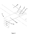
- FIG 2 an exemplary embodiment of the invention is illustrated.
- three different illuminators (3) are positioned on the door (1).
- Three light paths on the apparatus (4) convey the light of the illuminators (3) to the Three light path exits which are on the vertical surface (4b).
- the ends of the light paths are shaped as typeface and symbol characters.
- the apparatus (4) of the invention in the exemplary embodiment in the figures is positioned on the door (1) by at least one connector (5) on the door (1).
- This connector (5) enables the apparatus (4) to be hinged slidingly to the front door (1). Therefore, the apparatus (4) can be dismounted for the assembly of the decorative door and its location can be adjusted by remount after assembly.
- the connector (5) enables the apparatus (4) to move to the outside of the machine (in -X direction) as shown in Figure 2 and to move towards the inside of the machine (in +X direction) as shown in Figure 3 .
- the ends of the light paths on the horizontal surface (4) have such a size that the ends remain on the illuminator (3) when the apparatus (4) move in +X and -X direction; thus ensuring the light of the illuminator (3) to be conveyed to the vertical surface (4b) in different horizontal positions.
Landscapes
- Washing And Drying Of Tableware (AREA)
Abstract
Description
- The present invention relates to a dishwasher comprising an apparatus which directs the light of an illuminator provided at the lateral surface of the front door.
- In dishwashers which are known as built-in dishwashers in prior art, a decorative panel can be mounted on the front door of the machine. Decorative panel can be in different colors, patterns and sizes according to the preferences of the user. Due to the decorative panel mounted on the front door of said dishwashers, the control panel which is situated on the front face of the front door in the said conventional dishwashers, which controls the functions of the device and which shows information about working modes of the device, cannot be situated on a front face of the front door in the built-in dishwashers. Preferably, control panel in the built-in dishwashers is situated on a lateral surface of the front door. Control panel situated on the lateral surface is become inaccessible during the operation of the dishwasher. Therefore, the user cannot see the information about the working mode during the washing.
- In the patent document no
EP1151717 B1 which discloses one of the embodiments concerning the solution of the said problem; a refraction element is located on a control panel on the lateral surface of the front door. Refraction element extends forwardly from the upper lateral surface of the front door and enables, by refracting the light of the illuminators on the control panel, the illuminators to become visible from the front face while the front door is closed. - In the patent document no
EP1702551A1 which discloses another embodiment of prior art, illuminators on the control panel are located on the front face of the front door. In order to make the illuminators visible from the decorative panel, an opening is formed on the decorative panel and a control front panel of the invention is situated in the opening. - Therefore, illuminators are moved to the top of the decorative panel. However, in the said embodiment the decorative panel needs to be treated. Therefore, the embodiment is not applicable by a user.
- The dishwasher of the present invention comprises at least one front door and at least one illuminator positioned on at least one lateral surface of the front door; at least one horizontal surface positioned on the front door so as to be placed on the said illuminator, at least one vertical surface which is connected to the horizontal surface and provided on at least one decorative panel on the front door when horizontal surface is placed on the illuminator; at least one illuminating apparatus at least one end of which is provided on the horizontal surface, at least one another end of which is positioned on the vertical surface and comprising at least one light path.
- Said apparatus is provided on the illuminator and conveys the light of the illuminator to the end on the vertical surface of the light path by directing the light along the light path. Apparatus has a movable structure and can be positioned on a decorative panel, where the vertical surface is mounted to the front door. Therefore, illuminator is moved onto the panel.
- The dishwasher of the present invention solves the problem that the illuminators, which show the working information, cannot be seen during the operation of the device in the built-in type dishwashers. Moreover, the apparatus used in the invention enables ease of application since the apparatus can easily be mounted to the device by the user.
- The aim of the present invention is to develop a dishwasher comprising an illuminating apparatus.
- The other aim of the present invention is to develop a dishwasher comprising an illuminating apparatus which can easily be mounted on the decorative panel, where a decorative panel can be mounted to the front door of the dishwasher.
-
-
Figure 1 is a perspective view of the front door of the dishwasher in an embodiment of the dishwasher of the present invention. -
Figure 2 is a detailed view of the illuminating apparatus in an embodiment of the dishwasher of the present invention. -
Figure 3 is another view of the illuminating apparatus in an embodiment of the dishwasher of the present invention. - The parts in the figures are individually enumerated and the corresponding terms of reference numbers are as follows:
Front door (1) Lateral surface (1a) Control panel (2) Illuminator (3) Illuminating apparatus (4) Horizontal surface (4a) Vertical surface (4b) Connector (5) - In an embodiment of the dishwasher of the present invention, a view of the front door of the dishwasher is illustrated in
Figure 1 . The dishwasher of the present invention comprises at least one front door (1) on which at least one decorative panel (not illustrated) is placed. At the at least one lateral surface (1a) of the front door (1), preferably at least one control panel (2) and at least one illuminator (3) which shows working mode of the machine are situated. - The machine comprises at least one illuminating apparatus (4) to enable the visibility of the illuminator (3) on the front door (1) while the machine is operating. Illuminating apparatus (4) comprises at least one horizontal surface (4a) and at least one vertical surface (4b) which is connected to the horizontal surface (4a). The apparatus (4) is situated on the front door (1) such that the said horizontal surface (4a) is placed on the illuminator (3). When the lateral surface (4a) is positioned on the front door (1), it entirely covers preferably the illuminator (3). Vertical surface (4b), connected to the horizontal surface (4a), is situated on the decorative panel on the front door (1) when the horizontal surface (4a) is positioned on the illuminator (3).
- At least one light path (not illustrated) is located on the illuminating apparatus (4). Light path directs the light of the illuminator on the apparatus (4). Light path can be formed by passing at least one fiber optical cable (not illustrated) through the apparatus (4) or by making the apparatus of transparent material and building at least one area in the apparatus (4),having refractive index different from the one of the apparatus (4) . One end of the light path opens preferably to the face of the horizontal surface (4a) of the apparatus (4) which contacts with the illuminator (3). Light path goes through in the horizontal surface (4a) and vertical surface (4b) and preferably opens to the end of the light path at the face of the vertical surface (4b) which users can see. Thus; the light of the illuminator (3) becomes visible at the vertical surface by being directed. Preferably, different light paths are used for different illuminators (3). These light paths reach to different light path ends on the vertical surface (4b) without crossing. Therefore, different ends are illuminated for different signals.
- In
figure 2 , an exemplary embodiment of the invention is illustrated. In the said embodiment, three different illuminators (3) are positioned on the door (1). Three light paths on the apparatus (4) convey the light of the illuminators (3) to the Three light path exits which are on the vertical surface (4b). The ends of the light paths are shaped as typeface and symbol characters. - The apparatus (4) of the invention in the exemplary embodiment in the figures is positioned on the door (1) by at least one connector (5) on the door (1). This connector (5) enables the apparatus (4) to be hinged slidingly to the front door (1). Therefore, the apparatus (4) can be dismounted for the assembly of the decorative door and its location can be adjusted by remount after assembly. The connector (5) enables the apparatus (4) to move to the outside of the machine (in -X direction) as shown in
Figure 2 and to move towards the inside of the machine (in +X direction) as shown inFigure 3 . The ends of the light paths on the horizontal surface (4) have such a size that the ends remain on the illuminator (3) when the apparatus (4) move in +X and -X direction; thus ensuring the light of the illuminator (3) to be conveyed to the vertical surface (4b) in different horizontal positions.
Claims (3)
- A dishwasher comprising at least one front door (1) and at least one illuminator (3) positioned on at least one lateral surface (1a) of the front door (1) characterized by comprising at least one horizontal surface (4a) positioned on the front door (1) so as to be placed on the said illuminator (3), at least one vertical surface (4b) which is connected to the horizontal surface (4a) and provided on at least one decorative panel on the front door (1) when horizontal surface (4a) is placed on the illuminator (3); at least one illuminating apparatus (4) at least one end of which is positioned on the horizontal surface (4a), at least one another end of which is positioned on the vertical surface (4b) and comprising at least one light path.
- A dishwasher according to the claim 1 characterized by comprising at least one connector (5) which enables the apparatus (4) to be mounted as sliding hinge to the front door (1) and which is positioned on the front door (1).
- A dishwasher according to the claim 2 characterized in that the connector (5) is such a connector (5) that it enables the apparatus (4) to move towards the inside of the machine (+X) and/or to move to the outside of the machine (- X).
Applications Claiming Priority (1)
| Application Number | Priority Date | Filing Date | Title |
|---|---|---|---|
| TR2010/06830A TR201006830A2 (en) | 2010-08-17 | 2010-08-17 | A dishwasher |
Publications (2)
| Publication Number | Publication Date |
|---|---|
| EP2420176A2 true EP2420176A2 (en) | 2012-02-22 |
| EP2420176A3 EP2420176A3 (en) | 2014-03-05 |
Family
ID=44512687
Family Applications (1)
| Application Number | Title | Priority Date | Filing Date |
|---|---|---|---|
| EP11175539.3A Withdrawn EP2420176A3 (en) | 2010-08-17 | 2011-07-27 | A dishwasher |
Country Status (2)
| Country | Link |
|---|---|
| EP (1) | EP2420176A3 (en) |
| TR (1) | TR201006830A2 (en) |
Cited By (3)
| Publication number | Priority date | Publication date | Assignee | Title |
|---|---|---|---|---|
| WO2015039774A1 (en) * | 2013-09-18 | 2015-03-26 | BSH Bosch und Siemens Hausgeräte GmbH | Display unit for a household appliance |
| EP2896344A1 (en) * | 2014-01-21 | 2015-07-22 | Miele & Cie. KG | Dishwasher |
| EP3050482A1 (en) * | 2015-01-21 | 2016-08-03 | BSH Hausgeräte GmbH | Domestic appliance |
Citations (2)
| Publication number | Priority date | Publication date | Assignee | Title |
|---|---|---|---|---|
| EP1151717B1 (en) | 2000-05-06 | 2003-12-17 | Miele & Cie. KG | Dishwasher, in particular built in dishwasher with an optical operating status display |
| EP1702551A1 (en) | 2006-03-31 | 2006-09-20 | V-Zug AG | Domestic appliance with decorative panel and optical display integrated therein |
Family Cites Families (5)
| Publication number | Priority date | Publication date | Assignee | Title |
|---|---|---|---|---|
| DE102004062751A1 (en) * | 2004-12-27 | 2006-07-06 | BSH Bosch und Siemens Hausgeräte GmbH | household appliance |
| DE102005047915A1 (en) * | 2005-10-06 | 2007-04-12 | BSH Bosch und Siemens Hausgeräte GmbH | Indicator light arrangement for built-in domestic appliance, e.g. dishwasher, involves a reflecting sealing strip in gap between unit fronts |
| DE102008043270A1 (en) * | 2008-10-29 | 2010-05-06 | BSH Bosch und Siemens Hausgeräte GmbH | Light-guiding element for built-in furniture for e.g. laundry dryer, has fastening unit for fastening at door of furniture, where element guides light emitted from rear of door to front side of door |
| US8007597B2 (en) * | 2008-12-09 | 2011-08-30 | Whirlpool Corporation | Dishwasher providing usage guidance |
| ITRN20100005A1 (en) * | 2010-03-02 | 2011-09-03 | Indesit Co Spa | APPLIANCE |
-
2010
- 2010-08-17 TR TR2010/06830A patent/TR201006830A2/en unknown
-
2011
- 2011-07-27 EP EP11175539.3A patent/EP2420176A3/en not_active Withdrawn
Patent Citations (2)
| Publication number | Priority date | Publication date | Assignee | Title |
|---|---|---|---|---|
| EP1151717B1 (en) | 2000-05-06 | 2003-12-17 | Miele & Cie. KG | Dishwasher, in particular built in dishwasher with an optical operating status display |
| EP1702551A1 (en) | 2006-03-31 | 2006-09-20 | V-Zug AG | Domestic appliance with decorative panel and optical display integrated therein |
Cited By (4)
| Publication number | Priority date | Publication date | Assignee | Title |
|---|---|---|---|---|
| WO2015039774A1 (en) * | 2013-09-18 | 2015-03-26 | BSH Bosch und Siemens Hausgeräte GmbH | Display unit for a household appliance |
| EP2896344A1 (en) * | 2014-01-21 | 2015-07-22 | Miele & Cie. KG | Dishwasher |
| DE102014100629A1 (en) * | 2014-01-21 | 2015-07-23 | Miele & Cie. Kg | dishwasher |
| EP3050482A1 (en) * | 2015-01-21 | 2016-08-03 | BSH Hausgeräte GmbH | Domestic appliance |
Also Published As
| Publication number | Publication date |
|---|---|
| TR201006830A2 (en) | 2010-12-21 |
| EP2420176A3 (en) | 2014-03-05 |
Similar Documents
| Publication | Publication Date | Title |
|---|---|---|
| CN101325902B (en) | Domestic appliance, in particular fitted domestic appliance with a controllable operating display | |
| EP1883338B1 (en) | Apparatus and method for vision testing | |
| EP1838201B1 (en) | Integrated operation display device | |
| EP2420176A2 (en) | A dishwasher | |
| EP3538702B1 (en) | Domestic appliance having a projection device, and method for the operation thereof | |
| DE10255006A1 (en) | Household appliance with a display device that can be integrated in a row of furniture | |
| EP2937456B1 (en) | Laundry treatment apparatus | |
| DE102004038418A1 (en) | System of a household appliance | |
| ATE256418T1 (en) | DISHWASHER, IN PARTICULAR A BUILT-IN DISHWASHER WITH AN OPTICAL OPERATION INDICATOR | |
| CN103126571A (en) | Washing dresser | |
| JP7084534B2 (en) | Photoelectric switch | |
| CN101349575B (en) | Photoelectric sensor | |
| ITRN20100005A1 (en) | APPLIANCE | |
| DE102016210171A1 (en) | Household appliance with illuminated rotary selector and method for operating the household appliance | |
| EP2552292B1 (en) | Dishwasher | |
| CN105780390B (en) | Household electrical appliance with guiding device | |
| DE10051299A1 (en) | Information system has signal-detection arrangement, output device with scanning projection device and scanning detection arrangement. | |
| US20110192551A1 (en) | Window blind assembly | |
| DE10349675A1 (en) | Vapor extraction device with a screen made of transparent material | |
| DE102013208374A1 (en) | Cleaning device with illuminated door handle | |
| DE102019209364A1 (en) | Laundry processing device | |
| KR101382736B1 (en) | Display apparatus | |
| JP6252522B2 (en) | Remote panel | |
| EP2896344A1 (en) | Dishwasher | |
| DE102017102888A1 (en) | Built-in household appliance, in particular dishwasher |
Legal Events
| Date | Code | Title | Description |
|---|---|---|---|
| AK | Designated contracting states |
Kind code of ref document: A2 Designated state(s): AL AT BE BG CH CY CZ DE DK EE ES FI FR GB GR HR HU IE IS IT LI LT LU LV MC MK MT NL NO PL PT RO RS SE SI SK SM TR |
|
| AX | Request for extension of the european patent |
Extension state: BA ME |
|
| PUAI | Public reference made under article 153(3) epc to a published international application that has entered the european phase |
Free format text: ORIGINAL CODE: 0009012 |
|
| PUAL | Search report despatched |
Free format text: ORIGINAL CODE: 0009013 |
|
| AK | Designated contracting states |
Kind code of ref document: A3 Designated state(s): AL AT BE BG CH CY CZ DE DK EE ES FI FR GB GR HR HU IE IS IT LI LT LU LV MC MK MT NL NO PL PT RO RS SE SI SK SM TR |
|
| AX | Request for extension of the european patent |
Extension state: BA ME |
|
| RIC1 | Information provided on ipc code assigned before grant |
Ipc: A47L 15/42 20060101AFI20140130BHEP |
|
| STAA | Information on the status of an ep patent application or granted ep patent |
Free format text: STATUS: THE APPLICATION IS DEEMED TO BE WITHDRAWN |
|
| 18D | Application deemed to be withdrawn |
Effective date: 20140906 |