EP2418977B1 - Garment measurer - Google Patents
Garment measurer Download PDFInfo
- Publication number
- EP2418977B1 EP2418977B1 EP09787706.2A EP09787706A EP2418977B1 EP 2418977 B1 EP2418977 B1 EP 2418977B1 EP 09787706 A EP09787706 A EP 09787706A EP 2418977 B1 EP2418977 B1 EP 2418977B1
- Authority
- EP
- European Patent Office
- Prior art keywords
- arm
- correspondence
- way
- supporting element
- length
- Prior art date
- Legal status (The legal status is an assumption and is not a legal conclusion. Google has not performed a legal analysis and makes no representation as to the accuracy of the status listed.)
- Not-in-force
Links
- 238000005259 measurement Methods 0.000 claims description 41
- 238000000605 extraction Methods 0.000 claims description 10
- 210000001624 hip Anatomy 0.000 description 11
- 125000006850 spacer group Chemical group 0.000 description 10
- 239000002184 metal Substances 0.000 description 7
- 230000000903 blocking effect Effects 0.000 description 6
- 230000008878 coupling Effects 0.000 description 4
- 238000010168 coupling process Methods 0.000 description 4
- 238000005859 coupling reaction Methods 0.000 description 4
- 239000004744 fabric Substances 0.000 description 2
- 210000004197 pelvis Anatomy 0.000 description 2
- 230000006978 adaptation Effects 0.000 description 1
- 230000009189 diving Effects 0.000 description 1
- 238000003780 insertion Methods 0.000 description 1
- 230000037431 insertion Effects 0.000 description 1
- 238000012423 maintenance Methods 0.000 description 1
- 238000000034 method Methods 0.000 description 1
- 238000011160 research Methods 0.000 description 1
- 230000000284 resting effect Effects 0.000 description 1
- 238000004904 shortening Methods 0.000 description 1
- 230000002459 sustained effect Effects 0.000 description 1
Images


Classifications
-
- A—HUMAN NECESSITIES
- A41—WEARING APPAREL
- A41H—APPLIANCES OR METHODS FOR MAKING CLOTHES, e.g. FOR DRESS-MAKING OR FOR TAILORING, NOT OTHERWISE PROVIDED FOR
- A41H1/00—Measuring aids or methods
- A41H1/02—Devices for taking measurements on the human body
- A41H1/04—Stands for taking measurements
Definitions
- the present invention refers to the tailor's technical field. In particular it refers to a device for the acquisition of measures for the realization or adjustment of clothing in general.
- the manual operation for measuring the waist is commonly made by turning around the waist of the person with the metre and reading the corresponding measure.
- the operation is not easy and often the operator cannot surround with the metre the body of the person in a precise way, especially if he's of small bulk. It is then frequent the case where the metre does not perfectly surround the waist of the client but result to be raised or dropped from it, maybe because it is not sufficiently tight. If the operator does not have much experience it is then frequent the case where the measure is not correct, causing a not good final result and a clothing that have not much precise measures.
- the measurement in the inner part of the leg for example for the realization or adjustment of a trousers, can create discomfort to both the operator and the client.
- the proposed solution comprises a bar 3 projecting a graduated scale and supported by a supporting base 1.
- Different measuring arms (7, 8, 9) are assembled in a sliding manner on the bar thanks to the help of couplings 4. In such manner, by making the arms sliding along the bar until the desired height is reached, the relative height can be read and found.
- a measurement strip 22 can be assembled on one of such sleeves in such a way to bring it to the desired height and read the circumference measure.
- the patent GB 365,836 in the name of Caraceni describes a simple device for measuring a body, comprising a height adjustable stand with a graduated scale, a projecting reference arm and an attached tape measure.
- the prefixed aims are obtained through the realization of a telescopic arm 2, or rather in a way to result selectively stretchable or retractible in order to take a measurement on the body.
- the arm can lengthen and get retracted into therefore a chosen length to allow to read a measurement. In such way it results to be not much cumbersome when put back into the closing position at the end of the measurement and thus also easily transportable.
- the arm comprises fixing means (6) to fix it at a chosen extraction length in such a way to allow to operate, in correspondence of such length, a reading of the measurement of the body.
- the arm (2) comprises a portion with a fixed base (4) and at least an upper portion (5) selectively extractable or retractable from/to the inside of said fixed portion.
- the arm comprises a sole upper portion (5) selectively extractable or retractable from the portion with fixed base (4).
- the portion with fixed base (4) comprises always a supporting base (3) in such a way that the arm (2) can, in its complex, be placed on the ground in a way to be emerging upward.
- the mentioned means (11, 13, 15, 18) to take the measures of the clothes comprise at least a supporting element (15) comprising at least a device (13, 14, 18, 19) that allows to read at least a length and/or a width of the body.
- the supporting element (15) is placed in correspondence or closed to the upper end of the upper portion (5).
- a possible constructive solution can comprise a sole supporting element 15 placed in correspondence of the portion 5 placed above.
- the supporting element is place at the top of such portion.
- the above mentioned devices comprise at least a reference lever (13) or a bracket suitable to indicate the reaching of the chosen measuring point of the length of the cloth in correspondence of the lengthening or of the retracting of the arm.
- the reference lever can be, for example, integrated to the supporting element (15).
- the head can comprise a hook (14) to receive the reference lever.
- the hook (14) can then be of magnetic type while the lever (13) of metallic type in such a way to remain into the position on the hook.
- the supporting element is placed on the top of the portion 5 and comprises in an integrated or detached manner the bracket 13, it is also comprised a graduated scale (11) placed along said portion (5) and made in such a way to indicate the reached length in correspondence of the extraction or retraction of the upper portion (5) respect to the fixed base portion (4).
- the graduated scale works thus in combination with the reference bar 13 in a way to indicate the length measure of the body.
- the bar indicates the length where the extraction of the arm 2 must be stopped while the graduated scale indicates such length.
- a particularly advantageous solution comprises the graduated scale (11) engraved directly on the upper portion (5).
- the supporting element (15) comprises also a site (17) suitable to comprise a metre (18) configured to allow to take a measure of a circumference in correspondence of the chosen length of the arm.
- the site 17 for the metre can be placed at a height corresponding to 6. 5 centimetres from the bracket 13 when placed on the supporting element 15. In such manner, during the specific measurement of the crotch of a trouser, it is automatically obtained also the pelvis measurement independently from who takes these measures, even if the person has no experience.
- the site is closed at the top by an upper lid (16) in such a way to bind the metre within the site.
- the means (6) to fix the arm at the chosen length comprise a knob (7) and a carved spacer (8) and are configures with such a diameter to surround the upper portion (5).
- knob is made to get screwed at the upper end of the fixed portion (4) in such a way to close the spacer around the upper portion fixing it into the position or to get unscrewed to allow to the spacer to release the upper portion.
- This mechanism particularly simple constructively, allows to fix into the position the eventual movable portion/s 5 respect to the fixed one 4.
- Figure 1 shows, according to the invention, a complex view of the device for taking the measures on a body in general, particularly bodies of a person, for making clothing.
- the invention comprises an arm or bar 2 and means (11, 13, 15, 18) to allow to a user to take the measures that are specified further on in more detail.
- the arm 2 is sustained through a supporting base 3 in such a way to be placed on the ground and emerge upwards.
- the arm 2 is of telescopic type, or rather comprises some singular portions (indicated in the figure with the number 4 and 5) configured one inside the other in such a way to result selectively extractable and retractable.
- the arm result selectively stretchable and retractable and, according to such solution, the encumbrances in the retracted position are reduced as much as possible.
- the fixed base portion 4 comprising the above mentioned supporting base 3 is configured to receive at least an upper portion 5 sliding in its inside.
- the portion 4 is obviously hollowed, in such a way to be able to assemble in a sliding manner in its inside the different upper portions 5 (for such aim look also at the details of figure 2 and 3 ).
- the figure 1 described the preferred solution of the invention constituted by a sole portion 5 sliding within said base 4.
- a blocking element 6 that can be selectively screwed and unscrewed (look at figure 1 and figure 2 ), is fixed in correspondence of the upper free end of the portion 4 by means of a common thread 9. By screwing the element 6 it is possible to fix into the position the portion 5 in correspondence of the chosen position. At the same manner, by unscrewing the blocking element, it is possible to make the portion 5 sliding respect to the fixed portion 4, be able this way to lift it or re-enter it respect to the mentioned portion 4 exactly as indicated by the double arrow of figure 1 .
- the fixed portion 4 comprises the thread 9 in correspondence of its upper end in a way to be able to couple the blocking element 6 to it.
- the blocking element comprises in combination a knob or metal ring 7 and a carved spacer 10 in such a way to lean around the circular perimeter of the portion 4 without falling into it.
- figure 4 indicates the coupling between the spacer and the upper portion 5 destined to enter in the site of the base portion 4.
- the knob and the spacer have thus a passing coaxial hole to allow the passage of the portion 5 which results sliding respect to the fixed portion as described in figure 1 .
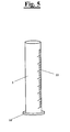
- the preferred solution of the invention comprises also a graduated scale 11 of length measurement directly obtained on the upper portion 5. Its functionality will be better explained later on.
- the upper end or the top of the portion 5 assembles a supporting element 15 for at least a device (13, 18) that allows the reading of the measures respect to the body, in particular the reading of a length and/or circumference.
- the supporting element can indifferently be in a sole piece with the mentioned portion 5 or separately connected to it.
- a reference bar 13 or bracket can be directly connected, for example welded, in a point of the perimeter of the supporting element 15.
- the supporting element comprises, according to the preferred solution, a shaped hook 14 to bind, by snap or through for example a magnet, the reference bar 13 (for such aim look at figure 1 and 6 ) of which the functionality will be better explained further on.
- the bar is then realized in two portions that result to be respectively pivoted. In such manner the bar can be configured according to a substantially I shape in a closed condition and an L configuration in a using condition.
- the supporting element 15 comprises an internal site 17 limited at the top by an upper closing lid 16.
- the lid can be fixed through simple screws or similar devices and result thus easily removable.
- the site 17 receives in its inside a traditional metre 18 with an internal spring of automatic wrap type suitable for measuring the circumference.
- the frontal and lateral view shown in figure 6 both show the head 15 and the metre 18 assembled in its inside. In such manner the user can selectively extract the strip 19 to make the measurement and retract it by simply pushing the releasing button typical of such metres while the container of the same 18 is maintained fixed within the site.
- the same upper closing lid 16 of the site can realize an interference such to maintain the metre within the site 17. In such case its removal is possible further to the disassembling of the lid.
- Other equivalent blocking solution of the metre within the site can anyway be used without having for this reason to move apart from the present inventive concept.
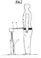
- Figure 7 and 8 show a body of a person in order to detail the using phases of the present device.
- the operator that has to take the measures places the device close to the body.
- By simply extracting or retracting the movable portion respect to the fixed one it is possible to place the supporting element 15 at the desired height.
- Particularly figure 8 shows a height signed by the reference bar 13.
- the graduated scale indicates the length.
- Figure 7 shows, only for convenience, the bar 13 placed back to the resting position in correspondence of the hook obtained on the base 4.
- the instrument is initially placed at the side of the person, or at the left or at the right.
- the bracket is thus removed by the specific magnetic hold support and inserted on top of said element 15.
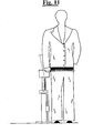
- the metre is wrapped around the pelvis of the person (look at figure 10 ).
- electronic saving devices as for example a computer, can allow to save directly the taken data on a CD in a way to store them until the cloth is made.
Description
- The present invention refers to the tailor's technical field. In particular it refers to a device for the acquisition of measures for the realization or adjustment of clothing in general.
- It is known how, after clothes are bought, it is often required the help of a tailor or an operator to realize adjustments and adaptations of the same respect to the body of the buyer. For example it is frequent and common the purchase of clothes in clothing shops. In such cases the client can anyway ask to adjust some measures of the acquired clothes in order to adapt it to his own body. For example it could be asked to tighten the shoulders of a jacket, or the waist of a shirt. These are some of the examples of changes that can be asked to the shopkeeper.
- Moreover, it is very frequent also the case where the people result to be absolutely out of the ordinary standard measures of the industrial type clothing. In such case, it is really needed to buy cut-made clothes which, even if they sometimes have a higher cost respect to the common industrially made clothes, the comfort that they offer when are put on is anyway substantial. Moreover, adapting perfectly to the specific measures of the person, guarantee a precious aesthetic result. Such need is required also in the realization of specific sport clothing. This is for example the case of diving suits which are always more frequently realized custom made.
- In such situation, especially in the case of cut-made clothing, it is necessary that a person with experience, or rather a tailor, takes all the necessary measures of the person in order to be able to make the clothes. It is thus a common procedure to take directly on the body of the person the measures as for example the crotch of the trousers, the circumference of the waist and of the trunk , the height of the shoulders and other interested specific measures. All these measures allow then to the tailor to make trousers, jackets and clothes in general with specific wearability for the person who will wear them. Also in the case of a simple adjustment of the purchased clothes it is necessary that the tailor takes such measures on the person.
- In both the above mentioned cases it is thus clear how the operation of measuring is fundamental and how the final success of the clothes depends on it. Any wrong measurement can cause a final wrong realization and consequently unnecessary cost for the purchaser, other than his dissatisfaction. Moreover, in the case of custom-made clothes, it is necessary to take at least some fundamental measures of the body of the person, or it will possible to fail with the realization of the clothes.
- It is thus clear how such operation, if made by not much expert or not much careful people, can cause economic damages to the purchaser of the clothes who will have custom-made clothes different from his size, or even not made within the pre-established time limits because of some missing measures.
- Nowadays, not all the shopping centres have specialized persons and this would cause measuring result that are completely wrong. For example the manual operation for measuring the waist is commonly made by turning around the waist of the person with the metre and reading the corresponding measure. However, in the case for example of large size persons, the operation is not easy and often the operator cannot surround with the metre the body of the person in a precise way, especially if he's of small bulk. It is then frequent the case where the metre does not perfectly surround the waist of the client but result to be raised or dropped from it, maybe because it is not sufficiently tight. If the operator does not have much experience it is then frequent the case where the measure is not correct, causing a not good final result and a clothing that have not much precise measures.
- Moreover, also in the case of experienced operators, nowadays such operation requires some time in order to be made precisely. This implies a sacrifice to the client that has to pose for a long time in order to allow to finish the measurement.
- At last, the measurement in the inner part of the leg, for example for the realization or adjustment of a trousers, can create discomfort to both the operator and the client.
- In order to resolve different inconvenient between the ones mentioned above are proposed different solutions. For example, the patent
US 2,052,099 in the name of W. Litton of which are available only the drawings, clearly represents an old device that allows to take different measurements directly on the person in order to realize a clothing. The proposed solution comprises abar 3 projecting a graduated scale and supported by a supportingbase 1. Different measuring arms (7, 8, 9) are assembled in a sliding manner on the bar thanks to the help ofcouplings 4. In such manner, by making the arms sliding along the bar until the desired height is reached, the relative height can be read and found. In addition a measurement strip 22 can be assembled on one of such sleeves in such a way to bring it to the desired height and read the circumference measure. - However such device is very complex and has a bulky structure with a height that equals to at least a man with an average height. This makes it non transportable and thus not much easy to handle. This means that, in case of domicile works, the user will be forced to not use it. Moreover the device is perfectly destined to highly specialized persons and its structural complexity is such to make the operation even more complex than a normal measurement made manually, as in the tradition. Given its dimension and its structural complications, it can just be destined to a specialized group of people and not to a large distribution where are found also dealers of clothing made industrially.
- Moreover such structural complexity makes the same extreamely expensive. It is thus clear how such technical solution does not simplify the work but, in the contrary, makes it more complex requiring therefore a high competence for the use of the same.
- Other patents, as for example
US3,753,293 in the name of Branda et Al ., describe extremely complex and bulky devices where the extraction/retraction mechanism and raising/lowering movement allow to activate the measurement systems. However such devices imply the use of electronic and mechanical parts that are complex and expensive. Are also very hard to use, hardly transportable and do not allow fast measurements. Moreover they require a continuous maintenance of the mechanical parts that is extremely demanding. - The patent
GB 365,836 - The patent
US 2,645,015 in the name of Zielaskowski describes a simple device for taking the inseam measurement of trousers, comprising a height adjustable stand with a graduated scale and a projecting reference arm, but does not include any means for taking waist measurements. - It is therefore the aim of the present invention to give a device for the measurement of a body in order to make clothing that resolves the above inconvenience.
- In particular it is the aim of the present invention to give a device that allows to take the measures for making a clothing that is easy to use, allowing this way to take in a fast and precise manner all the required measurements.
- It is also the aim of the present invention to give a device that allows to take with accuracy the relative measurements for the realization of a clothing even by persons with not much experience in the field.
- It is also the aim of the present invention to give a device that is easily transportable and at the same time constructively simple, reducing in this way considerably both the productive and maintaining costs of the same.
- These and other aims are thus reached with the present devices for the reading of measures on a body of a person for the realization of a trouser according to
claims - In particular, the prefixed aims are obtained through the realization of a
telescopic arm 2, or rather in a way to result selectively stretchable or retractible in order to take a measurement on the body. - According to such solution the arm can lengthen and get retracted into therefore a chosen length to allow to read a measurement. In such way it results to be not much cumbersome when put back into the closing position at the end of the measurement and thus also easily transportable.
- In order to take the measurement through the mentioned means (11, 13, 15, 18) it is necessary to block the arm into the chosen position. For such aim the arm comprises fixing means (6) to fix it at a chosen extraction length in such a way to allow to operate, in correspondence of such length, a reading of the measurement of the body.
- It is clear how such solution is easy to use even for non expert people. By simply fixing the desired position, it is possible to read easily at least a corresponding measure on the body avoiding mistakes for example given by the lack of experience of the operator.
- Advantageously the arm (2) comprises a portion with a fixed base (4) and at least an upper portion (5) selectively extractable or retractable from/to the inside of said fixed portion.
- According then to a possible solution of the invention constructively simple, the arm comprises a sole upper portion (5) selectively extractable or retractable from the portion with fixed base (4).
- Both in the case of a constructive solution comprising different upper portions (5) and in the case of a sole upper portion (5), the portion with fixed base (4) comprises always a supporting base (3) in such a way that the arm (2) can, in its complex, be placed on the ground in a way to be emerging upward.
- Such solution is important because it gives a noteworthy efficiency to the present invention which can this way be placed on the ground close to the body and allow to the operator to comfortably take all the required measurements by simply lengthening or shortening the arm and fixing it then at the required position.
- For such aim, thus, the mentioned means (11, 13, 15, 18) to take the measures of the clothes comprise at least a supporting element (15) comprising at least a device (13, 14, 18, 19) that allows to read at least a length and/or a width of the body.
- In particular the supporting element (15) is placed in correspondence or closed to the upper end of the upper portion (5).
- In such manner the extraction and the retraction of the arm places the supporting element into the desired height and, at the same time, the operator can take the measures of the body by using in particular the devices (13, 18, 19).
- In much more detail, a possible constructive solution, can comprise a sole supporting
element 15 placed in correspondence of theportion 5 placed above. In particular, then, in the case of the solution with asole portion 5 it is clear that the supporting element is place at the top of such portion. - In particular, the above mentioned devices (13, 14, 18, 19) comprise at least a reference lever (13) or a bracket suitable to indicate the reaching of the chosen measuring point of the length of the cloth in correspondence of the lengthening or of the retracting of the arm.
- Between the different chosen solutions, the reference lever can be, for example, integrated to the supporting element (15).
- It is thus clear how such solution with the use of the bracket (13), other than having the advantage of a simple and fast measurement, resolves the problem of an embarrassing measurement for the client and the operator in the case where the crotch is measured.
- Alternatively the head can comprise a hook (14) to receive the reference lever.
- According to such last solution, the hook (14) can then be of magnetic type while the lever (13) of metallic type in such a way to remain into the position on the hook.
- In such case, thus, there is the advantage of a device that is more less cumbersome and constructively simple. Indeed, instead of realizing a head that brings integrated a
lever 13 projecting outward, it is realized a fast unhooking element. When it is removed the lever from the head after the use it can be placed apart, reducing much more this way the encumbrances and making the transportation of the same easier. - According then to the mentioned solutions, where the supporting element is placed on the top of the
portion 5 and comprises in an integrated or detached manner thebracket 13, it is also comprised a graduated scale (11) placed along said portion (5) and made in such a way to indicate the reached length in correspondence of the extraction or retraction of the upper portion (5) respect to the fixed base portion (4). - The graduated scale works thus in combination with the
reference bar 13 in a way to indicate the length measure of the body. - In particular the bar indicates the length where the extraction of the
arm 2 must be stopped while the graduated scale indicates such length. - A particularly advantageous solution comprises the graduated scale (11) engraved directly on the upper portion (5).
- In such case then, further to the extraction or retraction of the
portion 5 until when thereference bar 13 indicates the desired point on the body, it will be possible to read the length measure directly on the graduatedscale 11, taking as reference for example the upper edge of the fixedportion 4 within which themovable portion 5 enters. - Moreover it is also possible to integrate a digital display in correspondence of the supporting
element 15 which visualizes directly the measurement, avoiding this way to the user to bend down in order to check the graduatedbar 11. The display is thus connected to some common means for electric reading which visibly show on the reader the extraction measure of the telescopic arm and thus the measure of the height. - The supporting element (15) comprises also a site (17) suitable to comprise a metre (18) configured to allow to take a measure of a circumference in correspondence of the chosen length of the arm.
- In such manner, when the desired height is reached, it is possible to take other than a length also a measurement of the width or circumference of the body. Advantageously the
site 17 for the metre can be placed at a height corresponding to 6. 5 centimetres from thebracket 13 when placed on the supportingelement 15. In such manner, during the specific measurement of the crotch of a trouser, it is automatically obtained also the pelvis measurement independently from who takes these measures, even if the person has no experience. - Alternatively, equivalent solutions that comprise the sole site (17) for the reading of the circumference can be realized.
- Advantageously the site is closed at the top by an upper lid (16) in such a way to bind the metre within the site.
- Advantageously the means (6) to fix the arm at the chosen length comprise a knob (7) and a carved spacer (8) and are configures with such a diameter to surround the upper portion (5).
- Moreover the knob is made to get screwed at the upper end of the fixed portion (4) in such a way to close the spacer around the upper portion fixing it into the position or to get unscrewed to allow to the spacer to release the upper portion.
- This mechanism, particularly simple constructively, allows to fix into the position the eventual movable portion/
s 5 respect to thefixed one 4. - Further features and advantages according to the present invention will be clearer with the description of one of its pattern realization that follows, made to illustrate but not limit, with reference to the annexed drawings, in which:
-
Figure 1 represents a complex view of the present device according to the invention; -
Figure 2 represents a section that shows the coupling of theknob 7 with the carvedspacer 8 and the fixedbase portion 4; -
Figure 3 shows, for clearance, a view of the coupling shown infigure 2 ; -
Figure 4 represents the insertion of theknob 7 on top of theupper portion 5 of thearm 2. -
Figure 5 shows a view in detail of anupper portion 5 on graduated scale of measurement for the length; -
Figure 6 shoes a complex view of thehead 15 and two respectively lateral and frontal view of the head that assembles the meter for the circumference measurement; -
Figure 7 and8 show two phases of the circumference and height measurement according to the invention. - Figures from 9 to 11 show realization phases of a trouser, according to the use of the present invention.
-
Figure 1 shows, according to the invention, a complex view of the device for taking the measures on a body in general, particularly bodies of a person, for making clothing. In its most essential aspects, the invention comprises an arm orbar 2 and means (11, 13, 15, 18) to allow to a user to take the measures that are specified further on in more detail. - The
arm 2 is sustained through a supportingbase 3 in such a way to be placed on the ground and emerge upwards. - Still as described in
figure 1 , thearm 2 is of telescopic type, or rather comprises some singular portions (indicated in the figure with thenumber 4 and 5) configured one inside the other in such a way to result selectively extractable and retractable. In such manner the arm result selectively stretchable and retractable and, according to such solution, the encumbrances in the retracted position are reduced as much as possible. - Still as described in
figure 1 , the fixedbase portion 4 comprising the above mentioned supportingbase 3 is configured to receive at least anupper portion 5 sliding in its inside. For such aim, theportion 4 is obviously hollowed, in such a way to be able to assemble in a sliding manner in its inside the different upper portions 5 (for such aim look also at the details offigure 2 and3 ). In particular thefigure 1 described the preferred solution of the invention constituted by asole portion 5 sliding within saidbase 4. - Still with reference to
figure 1 , a blockingelement 6 that can be selectively screwed and unscrewed (look atfigure 1 andfigure 2 ), is fixed in correspondence of the upper free end of theportion 4 by means of acommon thread 9. By screwing theelement 6 it is possible to fix into the position theportion 5 in correspondence of the chosen position. At the same manner, by unscrewing the blocking element, it is possible to make theportion 5 sliding respect to the fixedportion 4, be able this way to lift it or re-enter it respect to the mentionedportion 4 exactly as indicated by the double arrow offigure 1 . - As better described in the constructive detail of
figure 2 and3 , the fixedportion 4 comprises thethread 9 in correspondence of its upper end in a way to be able to couple the blockingelement 6 to it. The blocking element comprises in combination a knob ormetal ring 7 and a carvedspacer 10 in such a way to lean around the circular perimeter of theportion 4 without falling into it. In order to make it clear,figure 4 indicates the coupling between the spacer and theupper portion 5 destined to enter in the site of thebase portion 4. The knob and the spacer have thus a passing coaxial hole to allow the passage of theportion 5 which results sliding respect to the fixed portion as described infigure 1 . - In such manner, when used, by screwing the metal ring it is created a fixing action on the spacer that surrounds the
portion 5. Such action determinates the closing of the thread of the spacer on theportion 5 realizing a grip and thus a blocking bind of theportion 5 respect to theportion 4. The opposite operation, or rather by unscrewing theknob 7, implies a release of the spacer and this the possibility of theportion 5 to slide respect to theportion 4. - As shown in
figure 5 , the preferred solution of the invention comprises also a graduatedscale 11 of length measurement directly obtained on theupper portion 5. Its functionality will be better explained later on. - By turning back to
figure 1 , the upper end or the top of theportion 5 assembles a supportingelement 15 for at least a device (13, 18) that allows the reading of the measures respect to the body, in particular the reading of a length and/or circumference. The supporting element can indifferently be in a sole piece with the mentionedportion 5 or separately connected to it. - With reference to the above mentioned devices (13, 18) a
reference bar 13 or bracket can be directly connected, for example welded, in a point of the perimeter of the supportingelement 15. Alternatively, the supporting element comprises, according to the preferred solution, a shapedhook 14 to bind, by snap or through for example a magnet, the reference bar 13 (for such aim look atfigure 1 and6 ) of which the functionality will be better explained further on. The bar is then realized in two portions that result to be respectively pivoted. In such manner the bar can be configured according to a substantially I shape in a closed condition and an L configuration in a using condition. - According to the solution of the
magnet bar 13, it is then also comprised along the fixed portion 4 afurther hook 12. In such manner, once the bar is used, it is possible to remove it by themagnetic hook 4 of the head and place it in correspondence of thehook 12. Such solution is extremely convenient for saving encumbrances. - By looking at
figure 6 , the supportingelement 15 comprises aninternal site 17 limited at the top by anupper closing lid 16. The lid can be fixed through simple screws or similar devices and result thus easily removable. Thesite 17 receives in its inside atraditional metre 18 with an internal spring of automatic wrap type suitable for measuring the circumference. The frontal and lateral view shown infigure 6 both show thehead 15 and themetre 18 assembled in its inside. In such manner the user can selectively extract thestrip 19 to make the measurement and retract it by simply pushing the releasing button typical of such metres while the container of the same 18 is maintained fixed within the site. For such aim, for example, the sameupper closing lid 16 of the site can realize an interference such to maintain the metre within thesite 17. In such case its removal is possible further to the disassembling of the lid. Other equivalent blocking solution of the metre within the site can anyway be used without having for this reason to move apart from the present inventive concept. - Having thus substantially described the device in its essential technical aspects, it is now explained the functional aspect of this last one.
-
Figure 7 and8 show a body of a person in order to detail the using phases of the present device. The operator that has to take the measures places the device close to the body. By simply extracting or retracting the movable portion respect to the fixed one it is possible to place the supportingelement 15 at the desired height. Particularlyfigure 8 shows a height signed by thereference bar 13. In this manner, in correspondence of the extraction of the arm, the graduated scale indicates the length. At the same time, it is also possible to take a circumference measure by extracting thestrip 19 that constitutes themetre 18.Figure 7 shows, only for convenience, thebar 13 placed back to the resting position in correspondence of the hook obtained on thebase 4. - The following
figures 9 ,10 and11 show three further measurement phases for the realization of a trouser. - The instrument is initially placed at the side of the person, or at the left or at the right. The bracket is thus removed by the specific magnetic hold support and inserted on top of said
element 15. Follows the lifting of the millimetric telescopic arm in such a way that thebracket 13 touches the upper part of where the leg cross, fixing it with thespecific metal ring 7. It is then noted down the height resulting at the edge of the metal ring, obtaining this way the measurement of the inner part of the legs with a non excessive result. With the arm that is blocked as above, the metre is wrapped around the pelvis of the person (look atfigure 10 ). Being the metre placed at a prefixed position of the head, or rather at the exact height of 6.5cm from the crossing of the crotch (or rather from the bracket 13), at this point it is obtained the measurement of the waist in an automatic manner independently from who takes these measures, even if is a person with no experience. As shown infigure 11 , by unblocking the metal ring, it is raised the millimetric bar until the head of the meter is brought to the waist point desired of the person (generally above the hip) and then the metal ring is blocked again. The measure found at the height of the metal ring is read and noted down, and by wrapping the metre around the waist, as if it was a belt, it is unwrapped with the button and forced into the right tension desired by the client. In this manner it is obtained the height of the mast (obtainable with a simple calculation) and the circumference of the waist. - Thus it result clear from such description not only how simple and fast results the measurement, but also how it is possible to take in a precise manner the length and circumference placed at different heights. In such manner, the measures result accurate even if they have been taken by non expert operators.
- At last it is clear how such solution can be modified comprising a supporting
element 15 with nosite 17 and supplied with only areference bar 13 for the measurement of the length or, in the contrary, supplied exclusively with asite 17 for the measurement of the sole circumference, but these do not form part of the claimed invention. - Moreover electronic saving devices, as for example a computer, can allow to save directly the taken data on a CD in a way to store them until the cloth is made.
- Definitively, the above mentioned description of a specific realization pattern is able to show the invention from the conceptual point of view in a way that others, by using the prior art, can modify and/or adapt in different application such specific realization pattern without further researches and without moving apart from the present invention as defined by the claims.
Claims (10)
- Device for the reading of measures on a body of a person for the realization of a trouser comprising an arm (2) and means (11, 13, 15, 18) to take measurements of the trouser, said arm (2) being telescopic in such a way to result selectively stretchable or retractable and comprising also means (6) to fix said arm (2) at a chosen length in a way to allow to make in correspondence of said length through said means (11, 13, 15, 18) a reading of at least a measure on the body, wherein said arm (2) comprises a fixed base portion (4) and at least an upper portion (5) selectively extractable or retractable from/to the inside of said fixed portion, wherein it is also comprised a graduated scale (11) placed along said portion (5) and configured in such a way to indicate the reached length in correspondence of the extraction or retraction of said upper portion (5) respect to said fixed base portion (4) and wherein said means (11, 13, 15, 18) to take measures of the trouser comprise a supporting element (15), placed in correspondence or closed to the upper end of the upper portion (5), said supporting element (15) comprising a device (13, 14, 18, 19) that allows to read at least a length and/or a width of the body, said device (13, 14, 18, 19) comprising a reference lever (13) that indicates in use where the legs of the body cross in correspondence of said stretching or retraction of the arm (2), characterized by said supporting element (15) comprising a shaped hook (14) for engaging in a removable manner the reference lever (13), and wherein said supporting element (15) comprises also a site (17) into which a metre (18) is assembled, the metre (18) being provided with a strip (19) with an internal spring of automatic wrap and configured to allow to take a measurement of a circumference in correspondence of the chosen length of the arm (2), said site (17) being positioned at a distance above the shaped hook (14).
- Device, according to claim 1, where said fixed base portion (4) comprises a supporting base (3) in such a way that said arm (2) can be placed on the ground in a way to be emerging upward.
- Device, according to claim 1, where said hook (14) is of magnetic type and the lever (13) is metallic in a way to remain into the hooking position.
- Device, according to claim 1, where said graduated scale (11) is carved on said upper portion (5).
- Device, according to one or more of the previous claims, where said head (15) comprises also a display to visualize the length measurement reached and electronic reading means connected to said display to send to the reader said measure.
- Device, according to one or more of the previous claims, where said metre (18) is placed at a height of 6.5 cm respect to the positioning of said reference lever (13) when placed on said supporting element (15).
- Device, according to claim 1, where said site is closed at the top by an upper lid (16) in a way to bind the metre within the site.
- Device, according to claim 1 and 3, wherein the fixed portion (4) comprises a further hook (12) in such a manner that, once the bar is used, it is possible to remove it by the magnetic hook (14) on the supporting element (15) and place it in correspondence of the hook (12).
- Device, according to any previous claim, wherein the reference lever (13) is realized in two portions that result to be respectively pivoted in a such a manner that the reference lever can be configured according to a substantially I shape in a closed position and an L configuration in a using position when inserted in the shaped hook.
- Device for the reading of measures on a body of a person for the realization of a trouser comprising an arm (2) and means (11, 13, 15, 18) to take measurements of the trouser, said arm (2) being telescopic in such a way to result selectively stretchable or retractable and comprising also means (6) to fix said arm (2) at a chosen length in a way to allow to make in correspondence of said length through said means (11, 13, 15, 18) a reading of at least a measure on the body, wherein said arm (2) comprises a fixed base portion (4) and at least an upper portion (5) selectively extractable or retractable from/to the inside of said fixed portion, wherein it is also comprised a graduated scale (11) placed along said portion (5) and configured in such a way to indicate the reached length in correspondence of the extraction or retraction of said upper portion (5) respect to said fixed base portion (4) and said means (11, 13, 15, 18) to take measures of the trouser comprise a supporting element (15), placed in correspondence or closed to the upper end of the upper portion (5), said supporting element (15) comprising a device (13, 14, 18, 19) that allows to read at least a length and/or a width of the body, said device (13, 14, 18, 19) comprising a reference lever (13) that indicate in use where the legs of the body cross in correspondence of said stretching or retraction of the arm, said reference lever (13) being integrated in the supporting element (15) and characterized by the fact that said supporting element (15) comprises also a site (17) into which a metre (18) is assembled, the metre (18) being provided with a strip (19) with an internal spring of automatic wrap and configured to allow to take a measurement of a circumference in correspondence of the chosen length of the arm (2), said site (17) being positioned at a distance above the reference lever (13).
Applications Claiming Priority (1)
| Application Number | Priority Date | Filing Date | Title |
|---|---|---|---|
| PCT/IT2009/000172 WO2010119463A1 (en) | 2009-04-16 | 2009-04-16 | Garment measurer |
Publications (2)
| Publication Number | Publication Date |
|---|---|
| EP2418977A1 EP2418977A1 (en) | 2012-02-22 |
| EP2418977B1 true EP2418977B1 (en) | 2014-11-05 |
Family
ID=41404083
Family Applications (1)
| Application Number | Title | Priority Date | Filing Date |
|---|---|---|---|
| EP09787706.2A Not-in-force EP2418977B1 (en) | 2009-04-16 | 2009-04-16 | Garment measurer |
Country Status (3)
| Country | Link |
|---|---|
| US (1) | US8756820B2 (en) |
| EP (1) | EP2418977B1 (en) |
| WO (1) | WO2010119463A1 (en) |
Families Citing this family (4)
| Publication number | Priority date | Publication date | Assignee | Title |
|---|---|---|---|---|
| US8464391B2 (en) | 2007-04-03 | 2013-06-18 | Diversey, Inc. | Mop head fixation device and method |
| USD719712S1 (en) | 2012-09-07 | 2014-12-16 | Diversey, Inc. | Floor maintenance tool |
| US9696128B2 (en) * | 2013-11-01 | 2017-07-04 | Kurt Ott | Measuring accessory for tools |
| CN112515267A (en) * | 2020-11-25 | 2021-03-19 | 广东元一科技实业有限公司 | Device for measuring human body size |
Citations (2)
| Publication number | Priority date | Publication date | Assignee | Title |
|---|---|---|---|---|
| GB365836A (en) * | 1931-02-17 | 1932-01-28 | Domenico Caraceni | Improvements in or relating to measuring devices for wearing apparel |
| US3816925A (en) * | 1973-03-26 | 1974-06-18 | Rabone Chesterman Ltd | Tape measures |
Family Cites Families (17)
| Publication number | Priority date | Publication date | Assignee | Title |
|---|---|---|---|---|
| US177702A (en) * | 1876-05-23 | Improvement in tailors measures | ||
| US1168431A (en) * | 1912-10-31 | 1916-01-18 | Julius Schuman | Measuring instrument. |
| GB191510201A (en) * | 1915-07-13 | 1916-05-11 | Peter Falkivitch | A New or Improved Apparatus for Measuring and Facilitating the Measurement of the Human Form. |
| US2196145A (en) * | 1939-03-15 | 1940-04-02 | Stanziale Enrico | Marking device |
| US2246744A (en) * | 1940-08-03 | 1941-06-24 | George K Manus | Tailor's measuring apparatus |
| US2645015A (en) * | 1952-02-18 | 1953-07-14 | Orville W Zielaskowski | Device for taking inseam measurement of trousers |
| US2763062A (en) * | 1953-05-21 | 1956-09-18 | Daniel Eisenberg | Skirt marker |
| US2795852A (en) * | 1955-11-17 | 1957-06-18 | John B Ermilio | Tailor's measuring device |
| US2818648A (en) * | 1956-04-06 | 1958-01-07 | Jochheim Hans Rudolf August | Posture measuring device |
| US3031215A (en) * | 1958-12-11 | 1962-04-24 | Edward G Vance | Portable light |
| FR1404501A (en) * | 1964-04-28 | 1965-07-02 | Apparatus for justifying complex measurements of the human body for cutting clothing | |
| US3418717A (en) * | 1966-11-15 | 1968-12-31 | Irving L Wilson Company | Measuring apparatus |
| US3439424A (en) * | 1967-06-12 | 1969-04-22 | Irving L Wilson Co | Measuring apparatus |
| US5094418A (en) * | 1990-09-07 | 1992-03-10 | Stryker Corporation | IV pole |
| JPH08243089A (en) * | 1995-03-13 | 1996-09-24 | Isamu Minami | Dislocation quantity-measuring equipment |
| US6754974B2 (en) * | 2002-09-13 | 2004-06-29 | Antonio Bassolino | Distance-comparison device |
| WO2004049848A1 (en) * | 2002-12-02 | 2004-06-17 | Fernando Rego | Tailoring guide system |
-
2009
- 2009-04-16 EP EP09787706.2A patent/EP2418977B1/en not_active Not-in-force
- 2009-04-16 US US13/262,641 patent/US8756820B2/en not_active Expired - Fee Related
- 2009-04-16 WO PCT/IT2009/000172 patent/WO2010119463A1/en active Application Filing
Patent Citations (2)
| Publication number | Priority date | Publication date | Assignee | Title |
|---|---|---|---|---|
| GB365836A (en) * | 1931-02-17 | 1932-01-28 | Domenico Caraceni | Improvements in or relating to measuring devices for wearing apparel |
| US3816925A (en) * | 1973-03-26 | 1974-06-18 | Rabone Chesterman Ltd | Tape measures |
Also Published As
| Publication number | Publication date |
|---|---|
| US20120023764A1 (en) | 2012-02-02 |
| WO2010119463A1 (en) | 2010-10-21 |
| EP2418977A1 (en) | 2012-02-22 |
| US8756820B2 (en) | 2014-06-24 |
Similar Documents
| Publication | Publication Date | Title |
|---|---|---|
| EP2418977B1 (en) | Garment measurer | |
| JP4579476B2 (en) | Display stand | |
| US7685727B2 (en) | Measuring device for garment tailoring, and related methods | |
| US6813838B2 (en) | Garment fitting system | |
| US2053810A (en) | Measuring apparatus | |
| US20040107593A1 (en) | Tailoring guide system | |
| US7832569B1 (en) | Adjustable clothing display rack | |
| US2016967A (en) | Golf bag support | |
| AU2011346886C1 (en) | Portable luggage scale | |
| CN107518482A (en) | A kind of amount body device of dress designing | |
| CN108577318B (en) | Exoskeleton working chair and using method thereof | |
| KR101812902B1 (en) | Apparatus for three-dimensional measurement of Breast shape | |
| CN112515267A (en) | Device for measuring human body size | |
| US2112928A (en) | Inseam measuring device | |
| US4674189A (en) | Tailor's marker and method | |
| CN213431120U (en) | Auxiliary dressing wheelchair | |
| CN111264952B (en) | A auxiliary device that is used for suit dress designing's quick measurement | |
| US869169A (en) | Tape-measure. | |
| US2509723A (en) | Girdle drier | |
| CN216601791U (en) | Clothing design volume body device | |
| KR200481680Y1 (en) | Umbrella Having Rotary Type Handle | |
| US2534757A (en) | Dress form | |
| KR20230079316A (en) | A tapeline | |
| WO2006040681A1 (en) | Device for transporting coffins | |
| EP2702883B1 (en) | Removable all-in-one kit device for a bow-tie |
Legal Events
| Date | Code | Title | Description |
|---|---|---|---|
| PUAI | Public reference made under article 153(3) epc to a published international application that has entered the european phase |
Free format text: ORIGINAL CODE: 0009012 |
|
| 17P | Request for examination filed |
Effective date: 20111024 |
|
| AK | Designated contracting states |
Kind code of ref document: A1 Designated state(s): AT BE BG CH CY CZ DE DK EE ES FI FR GB GR HR HU IE IS IT LI LT LU LV MC MK MT NL NO PL PT RO SE SI SK TR |
|
| DAX | Request for extension of the european patent (deleted) | ||
| 17Q | First examination report despatched |
Effective date: 20120802 |
|
| GRAP | Despatch of communication of intention to grant a patent |
Free format text: ORIGINAL CODE: EPIDOSNIGR1 |
|
| INTG | Intention to grant announced |
Effective date: 20131112 |
|
| GRAS | Grant fee paid |
Free format text: ORIGINAL CODE: EPIDOSNIGR3 |
|
| GRAA | (expected) grant |
Free format text: ORIGINAL CODE: 0009210 |
|
| AK | Designated contracting states |
Kind code of ref document: B1 Designated state(s): AT BE BG CH CY CZ DE DK EE ES FI FR GB GR HR HU IE IS IT LI LT LU LV MC MK MT NL NO PL PT RO SE SI SK TR |
|
| REG | Reference to a national code |
Ref country code: GB Ref legal event code: FG4D |
|
| REG | Reference to a national code |
Ref country code: CH Ref legal event code: EP |
|
| REG | Reference to a national code |
Ref country code: AT Ref legal event code: REF Ref document number: 694111 Country of ref document: AT Kind code of ref document: T Effective date: 20141115 |
|
| REG | Reference to a national code |
Ref country code: IE Ref legal event code: FG4D |
|
| REG | Reference to a national code |
Ref country code: DE Ref legal event code: R096 Ref document number: 602009027607 Country of ref document: DE Effective date: 20141218 |
|
| REG | Reference to a national code |
Ref country code: AT Ref legal event code: MK05 Ref document number: 694111 Country of ref document: AT Kind code of ref document: T Effective date: 20141105 |
|
| REG | Reference to a national code |
Ref country code: NL Ref legal event code: VDEP Effective date: 20141105 |
|
| REG | Reference to a national code |
Ref country code: LT Ref legal event code: MG4D |
|
| PG25 | Lapsed in a contracting state [announced via postgrant information from national office to epo] |
Ref country code: ES Free format text: LAPSE BECAUSE OF FAILURE TO SUBMIT A TRANSLATION OF THE DESCRIPTION OR TO PAY THE FEE WITHIN THE PRESCRIBED TIME-LIMIT Effective date: 20141105 Ref country code: NO Free format text: LAPSE BECAUSE OF FAILURE TO SUBMIT A TRANSLATION OF THE DESCRIPTION OR TO PAY THE FEE WITHIN THE PRESCRIBED TIME-LIMIT Effective date: 20150205 Ref country code: NL Free format text: LAPSE BECAUSE OF FAILURE TO SUBMIT A TRANSLATION OF THE DESCRIPTION OR TO PAY THE FEE WITHIN THE PRESCRIBED TIME-LIMIT Effective date: 20141105 Ref country code: FI Free format text: LAPSE BECAUSE OF FAILURE TO SUBMIT A TRANSLATION OF THE DESCRIPTION OR TO PAY THE FEE WITHIN THE PRESCRIBED TIME-LIMIT Effective date: 20141105 Ref country code: IS Free format text: LAPSE BECAUSE OF FAILURE TO SUBMIT A TRANSLATION OF THE DESCRIPTION OR TO PAY THE FEE WITHIN THE PRESCRIBED TIME-LIMIT Effective date: 20150305 Ref country code: LT Free format text: LAPSE BECAUSE OF FAILURE TO SUBMIT A TRANSLATION OF THE DESCRIPTION OR TO PAY THE FEE WITHIN THE PRESCRIBED TIME-LIMIT Effective date: 20141105 Ref country code: PT Free format text: LAPSE BECAUSE OF FAILURE TO SUBMIT A TRANSLATION OF THE DESCRIPTION OR TO PAY THE FEE WITHIN THE PRESCRIBED TIME-LIMIT Effective date: 20150305 |
|
| PG25 | Lapsed in a contracting state [announced via postgrant information from national office to epo] |
Ref country code: SE Free format text: LAPSE BECAUSE OF FAILURE TO SUBMIT A TRANSLATION OF THE DESCRIPTION OR TO PAY THE FEE WITHIN THE PRESCRIBED TIME-LIMIT Effective date: 20141105 Ref country code: GR Free format text: LAPSE BECAUSE OF FAILURE TO SUBMIT A TRANSLATION OF THE DESCRIPTION OR TO PAY THE FEE WITHIN THE PRESCRIBED TIME-LIMIT Effective date: 20150206 Ref country code: AT Free format text: LAPSE BECAUSE OF FAILURE TO SUBMIT A TRANSLATION OF THE DESCRIPTION OR TO PAY THE FEE WITHIN THE PRESCRIBED TIME-LIMIT Effective date: 20141105 Ref country code: LV Free format text: LAPSE BECAUSE OF FAILURE TO SUBMIT A TRANSLATION OF THE DESCRIPTION OR TO PAY THE FEE WITHIN THE PRESCRIBED TIME-LIMIT Effective date: 20141105 Ref country code: HR Free format text: LAPSE BECAUSE OF FAILURE TO SUBMIT A TRANSLATION OF THE DESCRIPTION OR TO PAY THE FEE WITHIN THE PRESCRIBED TIME-LIMIT Effective date: 20141105 Ref country code: PL Free format text: LAPSE BECAUSE OF FAILURE TO SUBMIT A TRANSLATION OF THE DESCRIPTION OR TO PAY THE FEE WITHIN THE PRESCRIBED TIME-LIMIT Effective date: 20141105 Ref country code: CY Free format text: LAPSE BECAUSE OF FAILURE TO SUBMIT A TRANSLATION OF THE DESCRIPTION OR TO PAY THE FEE WITHIN THE PRESCRIBED TIME-LIMIT Effective date: 20141105 |
|
| PG25 | Lapsed in a contracting state [announced via postgrant information from national office to epo] |
Ref country code: CZ Free format text: LAPSE BECAUSE OF FAILURE TO SUBMIT A TRANSLATION OF THE DESCRIPTION OR TO PAY THE FEE WITHIN THE PRESCRIBED TIME-LIMIT Effective date: 20141105 Ref country code: RO Free format text: LAPSE BECAUSE OF FAILURE TO SUBMIT A TRANSLATION OF THE DESCRIPTION OR TO PAY THE FEE WITHIN THE PRESCRIBED TIME-LIMIT Effective date: 20141105 Ref country code: SK Free format text: LAPSE BECAUSE OF FAILURE TO SUBMIT A TRANSLATION OF THE DESCRIPTION OR TO PAY THE FEE WITHIN THE PRESCRIBED TIME-LIMIT Effective date: 20141105 Ref country code: EE Free format text: LAPSE BECAUSE OF FAILURE TO SUBMIT A TRANSLATION OF THE DESCRIPTION OR TO PAY THE FEE WITHIN THE PRESCRIBED TIME-LIMIT Effective date: 20141105 Ref country code: DK Free format text: LAPSE BECAUSE OF FAILURE TO SUBMIT A TRANSLATION OF THE DESCRIPTION OR TO PAY THE FEE WITHIN THE PRESCRIBED TIME-LIMIT Effective date: 20141105 |
|
| REG | Reference to a national code |
Ref country code: DE Ref legal event code: R097 Ref document number: 602009027607 Country of ref document: DE |
|
| PLBE | No opposition filed within time limit |
Free format text: ORIGINAL CODE: 0009261 |
|
| STAA | Information on the status of an ep patent application or granted ep patent |
Free format text: STATUS: NO OPPOSITION FILED WITHIN TIME LIMIT |
|
| 26N | No opposition filed |
Effective date: 20150806 |
|
| PG25 | Lapsed in a contracting state [announced via postgrant information from national office to epo] |
Ref country code: LU Free format text: LAPSE BECAUSE OF FAILURE TO SUBMIT A TRANSLATION OF THE DESCRIPTION OR TO PAY THE FEE WITHIN THE PRESCRIBED TIME-LIMIT Effective date: 20150416 Ref country code: MC Free format text: LAPSE BECAUSE OF FAILURE TO SUBMIT A TRANSLATION OF THE DESCRIPTION OR TO PAY THE FEE WITHIN THE PRESCRIBED TIME-LIMIT Effective date: 20141105 |
|
| REG | Reference to a national code |
Ref country code: CH Ref legal event code: PL |
|
| REG | Reference to a national code |
Ref country code: IE Ref legal event code: MM4A |
|
| PG25 | Lapsed in a contracting state [announced via postgrant information from national office to epo] |
Ref country code: CH Free format text: LAPSE BECAUSE OF NON-PAYMENT OF DUE FEES Effective date: 20150430 Ref country code: LI Free format text: LAPSE BECAUSE OF NON-PAYMENT OF DUE FEES Effective date: 20150430 |
|
| PG25 | Lapsed in a contracting state [announced via postgrant information from national office to epo] |
Ref country code: SI Free format text: LAPSE BECAUSE OF FAILURE TO SUBMIT A TRANSLATION OF THE DESCRIPTION OR TO PAY THE FEE WITHIN THE PRESCRIBED TIME-LIMIT Effective date: 20141105 |
|
| REG | Reference to a national code |
Ref country code: FR Ref legal event code: PLFP Year of fee payment: 8 |
|
| PG25 | Lapsed in a contracting state [announced via postgrant information from national office to epo] |
Ref country code: IE Free format text: LAPSE BECAUSE OF NON-PAYMENT OF DUE FEES Effective date: 20150416 |
|
| PG25 | Lapsed in a contracting state [announced via postgrant information from national office to epo] |
Ref country code: MT Free format text: LAPSE BECAUSE OF FAILURE TO SUBMIT A TRANSLATION OF THE DESCRIPTION OR TO PAY THE FEE WITHIN THE PRESCRIBED TIME-LIMIT Effective date: 20141105 |
|
| REG | Reference to a national code |
Ref country code: FR Ref legal event code: PLFP Year of fee payment: 9 |
|
| PG25 | Lapsed in a contracting state [announced via postgrant information from national office to epo] |
Ref country code: BG Free format text: LAPSE BECAUSE OF FAILURE TO SUBMIT A TRANSLATION OF THE DESCRIPTION OR TO PAY THE FEE WITHIN THE PRESCRIBED TIME-LIMIT Effective date: 20141105 Ref country code: HU Free format text: LAPSE BECAUSE OF FAILURE TO SUBMIT A TRANSLATION OF THE DESCRIPTION OR TO PAY THE FEE WITHIN THE PRESCRIBED TIME-LIMIT; INVALID AB INITIO Effective date: 20090416 |
|
| PGFP | Annual fee paid to national office [announced via postgrant information from national office to epo] |
Ref country code: GB Payment date: 20170406 Year of fee payment: 9 |
|
| PG25 | Lapsed in a contracting state [announced via postgrant information from national office to epo] |
Ref country code: TR Free format text: LAPSE BECAUSE OF FAILURE TO SUBMIT A TRANSLATION OF THE DESCRIPTION OR TO PAY THE FEE WITHIN THE PRESCRIBED TIME-LIMIT Effective date: 20141105 |
|
| PG25 | Lapsed in a contracting state [announced via postgrant information from national office to epo] |
Ref country code: BE Free format text: LAPSE BECAUSE OF FAILURE TO SUBMIT A TRANSLATION OF THE DESCRIPTION OR TO PAY THE FEE WITHIN THE PRESCRIBED TIME-LIMIT Effective date: 20141105 |
|
| PG25 | Lapsed in a contracting state [announced via postgrant information from national office to epo] |
Ref country code: MK Free format text: LAPSE BECAUSE OF FAILURE TO SUBMIT A TRANSLATION OF THE DESCRIPTION OR TO PAY THE FEE WITHIN THE PRESCRIBED TIME-LIMIT Effective date: 20141105 |
|
| REG | Reference to a national code |
Ref country code: FR Ref legal event code: PLFP Year of fee payment: 10 |
|
| GBPC | Gb: european patent ceased through non-payment of renewal fee |
Effective date: 20180416 |
|
| PG25 | Lapsed in a contracting state [announced via postgrant information from national office to epo] |
Ref country code: GB Free format text: LAPSE BECAUSE OF NON-PAYMENT OF DUE FEES Effective date: 20180416 |
|
| PGFP | Annual fee paid to national office [announced via postgrant information from national office to epo] |
Ref country code: IT Payment date: 20210319 Year of fee payment: 13 |
|
| PGFP | Annual fee paid to national office [announced via postgrant information from national office to epo] |
Ref country code: FR Payment date: 20210419 Year of fee payment: 13 Ref country code: DE Payment date: 20210416 Year of fee payment: 13 |
|
| REG | Reference to a national code |
Ref country code: DE Ref legal event code: R119 Ref document number: 602009027607 Country of ref document: DE |
|
| PG25 | Lapsed in a contracting state [announced via postgrant information from national office to epo] |
Ref country code: FR Free format text: LAPSE BECAUSE OF NON-PAYMENT OF DUE FEES Effective date: 20220430 Ref country code: DE Free format text: LAPSE BECAUSE OF NON-PAYMENT OF DUE FEES Effective date: 20221103 |
|
| PG25 | Lapsed in a contracting state [announced via postgrant information from national office to epo] |
Ref country code: IT Free format text: LAPSE BECAUSE OF NON-PAYMENT OF DUE FEES Effective date: 20220416 |