EP2418472B1 - Device for assembling at least one sample container in an optical measuring device, optical measuring device with such a device and use of such an optical measuring device - Google Patents
Device for assembling at least one sample container in an optical measuring device, optical measuring device with such a device and use of such an optical measuring device Download PDFInfo
- Publication number
- EP2418472B1 EP2418472B1 EP10008445.8A EP10008445A EP2418472B1 EP 2418472 B1 EP2418472 B1 EP 2418472B1 EP 10008445 A EP10008445 A EP 10008445A EP 2418472 B1 EP2418472 B1 EP 2418472B1
- Authority
- EP
- European Patent Office
- Prior art keywords
- temperature
- carrier
- air
- sample container
- optical measuring
- Prior art date
- Legal status (The legal status is an assumption and is not a legal conclusion. Google has not performed a legal analysis and makes no representation as to the accuracy of the status listed.)
- Active
Links
- 230000003287 optical effect Effects 0.000 title claims description 20
- 238000009423 ventilation Methods 0.000 claims description 36
- 238000010438 heat treatment Methods 0.000 claims description 16
- 238000005496 tempering Methods 0.000 claims description 7
- 238000001816 cooling Methods 0.000 claims description 2
- 239000000523 sample Substances 0.000 description 67
- 239000003570 air Substances 0.000 description 47
- 230000005494 condensation Effects 0.000 description 16
- 238000009833 condensation Methods 0.000 description 16
- 238000005259 measurement Methods 0.000 description 13
- 230000005284 excitation Effects 0.000 description 9
- 238000004020 luminiscence type Methods 0.000 description 9
- XLYOFNOQVPJJNP-UHFFFAOYSA-N water Substances O XLYOFNOQVPJJNP-UHFFFAOYSA-N 0.000 description 8
- 108090000623 proteins and genes Proteins 0.000 description 6
- 239000007788 liquid Substances 0.000 description 5
- 241001465754 Metazoa Species 0.000 description 4
- 239000012080 ambient air Substances 0.000 description 4
- 230000000694 effects Effects 0.000 description 4
- 239000002609 medium Substances 0.000 description 4
- 239000007787 solid Substances 0.000 description 4
- 238000010586 diagram Methods 0.000 description 3
- 235000015097 nutrients Nutrition 0.000 description 3
- 238000010521 absorption reaction Methods 0.000 description 2
- 230000027288 circadian rhythm Effects 0.000 description 2
- 230000007423 decrease Effects 0.000 description 2
- 230000014509 gene expression Effects 0.000 description 2
- 238000012544 monitoring process Methods 0.000 description 2
- 102000004169 proteins and genes Human genes 0.000 description 2
- 241000894006 Bacteria Species 0.000 description 1
- 229910052782 aluminium Inorganic materials 0.000 description 1
- XAGFODPZIPBFFR-UHFFFAOYSA-N aluminium Chemical compound [Al] XAGFODPZIPBFFR-UHFFFAOYSA-N 0.000 description 1
- 230000003698 anagen phase Effects 0.000 description 1
- 238000013459 approach Methods 0.000 description 1
- 230000015572 biosynthetic process Effects 0.000 description 1
- 239000000969 carrier Substances 0.000 description 1
- 238000004113 cell culture Methods 0.000 description 1
- 238000011109 contamination Methods 0.000 description 1
- 238000005485 electric heating Methods 0.000 description 1
- 210000002257 embryonic structure Anatomy 0.000 description 1
- 230000007613 environmental effect Effects 0.000 description 1
- 238000001704 evaporation Methods 0.000 description 1
- 238000002474 experimental method Methods 0.000 description 1
- 230000002349 favourable effect Effects 0.000 description 1
- 239000012530 fluid Substances 0.000 description 1
- 238000002073 fluorescence micrograph Methods 0.000 description 1
- 239000011521 glass Substances 0.000 description 1
- 239000001963 growth medium Substances 0.000 description 1
- 230000007774 longterm Effects 0.000 description 1
- 239000000463 material Substances 0.000 description 1
- 229910052751 metal Inorganic materials 0.000 description 1
- 239000002184 metal Substances 0.000 description 1
- 238000000034 method Methods 0.000 description 1
- 230000008635 plant growth Effects 0.000 description 1
- 239000002244 precipitate Substances 0.000 description 1
- 238000011160 research Methods 0.000 description 1
- 229920006395 saturated elastomer Polymers 0.000 description 1
- 210000002023 somite Anatomy 0.000 description 1
- 239000000126 substance Substances 0.000 description 1
- 230000009261 transgenic effect Effects 0.000 description 1
- 230000007306 turnover Effects 0.000 description 1
Images

Classifications
-
- G—PHYSICS
- G01—MEASURING; TESTING
- G01N—INVESTIGATING OR ANALYSING MATERIALS BY DETERMINING THEIR CHEMICAL OR PHYSICAL PROPERTIES
- G01N21/00—Investigating or analysing materials by the use of optical means, i.e. using sub-millimetre waves, infrared, visible or ultraviolet light
- G01N21/62—Systems in which the material investigated is excited whereby it emits light or causes a change in wavelength of the incident light
- G01N21/63—Systems in which the material investigated is excited whereby it emits light or causes a change in wavelength of the incident light optically excited
- G01N21/64—Fluorescence; Phosphorescence
- G01N21/645—Specially adapted constructive features of fluorimeters
-
- G—PHYSICS
- G01—MEASURING; TESTING
- G01N—INVESTIGATING OR ANALYSING MATERIALS BY DETERMINING THEIR CHEMICAL OR PHYSICAL PROPERTIES
- G01N21/00—Investigating or analysing materials by the use of optical means, i.e. using sub-millimetre waves, infrared, visible or ultraviolet light
- G01N21/01—Arrangements or apparatus for facilitating the optical investigation
- G01N21/03—Cuvette constructions
- G01N21/0332—Cuvette constructions with temperature control
Definitions
- the invention relates to a device for arranging at least one sample vessel in an optical measuring device according to claim 1, an optical measuring device having such a device according to claim 11 and the use of such an optical measuring device according to claim 14.
- the generic FR 2 806 583 A1 shows an apparatus for monitoring plant growth.
- This device has a chamber in which the plants to be observed can be arranged.
- a ventilation device with a heating element, so that the air supplied to the chamber can be heated.
- Fluorescence and luminescence measuring methods have been used successfully in biological and pharmaceutical research for many years.
- transfected or transgenic animals or plants are used, wherein at least one gene of the plant or animal in question can encode a protein showing luminescence or fluorescence. If this gene is active, this protein is formed and, by monitoring its luminescence or fluorescence, one can draw conclusions about the activity of the gene in question and thus, for example, further conclude the efficacy of certain substances on the animal / plant.
- the measurement of the luminescence or fluorescence activity can be carried out integrally or spatially resolved.
- the sample containers for example Petri dishes
- the sample containers are at least closed, sometimes sterilized and sealed. This is usually done with transparent covers, which are additionally attached with tape or parafilm.
- the samples are usually located in the sample vessel in or on an aqueous liquid or solid medium.
- the at least one sample vessel is located on a carrier, which may be a simple plate.
- a carrier which may be a simple plate.
- such a carrier has depressions or the like, so that the carrier determines the geometric arrangement of the sample vessels.
- it is always referred to as multiple sample vessels, but it is clear that only one sample vessel can be present.
- an optical sensor unit - usually a photomultipier or a sensitive CCD camera - which is located above the at least one sample vessel.
- the present invention seeks to improve upon the prior art by improving the reproducibility of the luminescence or fluorescence measurements.
- This ventilation means is arranged to produce a heated air flow directed towards or over the covers and thus to heat the covers, thereby preventing condensation on the outside or inside of the tops of the sample vessels.
- a control circuit for controlling the ventilation device is provided. This is preferably set so that the heating of the lid by the ventilation device is just just so great that the temperature of the lid is always greater than the dew point of the air in the sample vessels and always greater than the dew point of the air outside the sample vessels.
- the support is temperature-controlled, so that the sample vessels and thus the plants / seedlings can be controlled in a controlled manner via the support and thus environmental conditions can be simulated.
- the dew point or dew point temperature is the temperature at which on a subject (for a given humidity) sets a Gieich.sschreib of condensing and evaporating water, in other words, the condensation is just beginning.
- the relative humidity in the air at a given pressure depends on the temperature. Air that is not completely saturated with water vapor has a relative humidity of less than 100% and can absorb further water vapor at the same temperature. If the temperature decreases, the absorption capacity of the air for water vapor also decreases, ie for a given humidity the relative humidity increases. At the dew point a relative humidity of 100% is reached, condensation occurs. In this case, a precipitate forms on solid or liquid interfaces, the effect is stronger, the lower the temperature of the interfaces or the higher the humidity.
- the dependence of the dew point on temperature and relative humidity can be taken from the known dew point curves.
- the lids are surrounded by tempered air, which is selected such that, given the relative humidity of the surrounding air inside or outside, the temperature of the lid is always sufficiently above the dew point.
- tempered air which is selected such that, given the relative humidity of the surrounding air inside or outside, the temperature of the lid is always sufficiently above the dew point.
- the plants themselves are introduced into an aqueous liquid or solid medium and possibly up to 100% relative humidity could be present, while it is generally much lower in the outer space in a housing of the meter.
- the higher dew point determines the minimum temperature of the lid, which must be sufficiently above this dew point, so that neither inside nor outside condensation can occur.
- the relative humidity of the air is 50%
- the temperature of the carrier on which the Petri dishes are located is 10 ° C
- the temperature of the air in the Petri dish above the plants is 12 ° C
- the relative humidity 90% is 90%.
- the dew point in the outer space of the Petri dish is 18 ° C
- the dew point in the interior is 11 ° C. If the cover of the Petri dish always open a temperature greater than 18 ° C, there can be no condensation from the outside and certainly not from the inside.
- the temperature of the air flow generated by the ventilation device is controlled so as to comply with the above dew point condition.
- the temperature of the lid is detected with a temperature sensor attached to a representative point and used in a first control loop as an actual value and constantly compared with the target value. In case of deviations, the temperature is readjusted accordingly by means of the ventilation device.
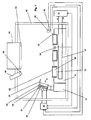
- the FIG. 1 shows an optical measuring device for measuring luminescence and / or fluorescence of plants or seedlings, which are in Petri dishes formed as sample vessels 50.
- sample vessels 50 As a rule, several such sample vessels 50 are present, for example, 9 pieces, only three can be seen due to the sectional view ,
- the sample containers 50 are closed with a lid 52 during the measurement.
- the sample containers 50 are arranged on a carrier 10 which has a recess 12 for each sample container.
- the carrier 10 is in the illustrated embodiment made of metal, in particular aluminum, and has a correspondingly high thermal conductivity.
- an optical measuring instrument here in the form of a camera, in particular a CCD camera 42 is arranged, which looks down in front of the entrance window of this camera 42, an emission filter 44 is arranged, which passes only light of a certain wavelength to the camera 42.
- an excitation light source 46 which points in the direction of the carrier 10 and in whose beam path an excitation filter 48 is present.
- the operation of such a fluorometer is basically known and need not be explained in detail here.
- the camera 42 can simultaneously see all the sample vessels 50 or for a relative movability between the carrier 10 and the camera 42 in the horizontal direction, so that the camera can only measure one sample vessel 50 (not shown).
- the excitation light source 46 this can either be designed so that it illuminates all the sample vessels 50 at the same time or it can be designed such that it illuminates only one sample vessel currently to be measured, in which case also a relative mobility between the excitation light source 46 and carrier 10 and / or a pivotability of the excitation light source 46 must be given.
- Carrier 10, entrance window of the camera 42 and exit window of the excitation light source 46 are located in a light-tight housing 40.
- the carrier 10 is tempered so that one can observe the plants / seedlings, which are located in the sample vessels 50, at different and defined temperatures.
- the temperature of the carrier takes place in the embodiment shown via a fluid circuit. This has within the carrier 10, a heat exchanger 14 and outside of the carrier 10, a temperature control unit 16, by means of which the circulated liquid (usually water) tempered, that is usually both heated and cooled, can be. Due to the recesses 12 (which in diameter substantially the diameters correspond to the sample vessels 50) take the sample vessels 50 substantially to the temperature of the carrier after a certain period of operation.
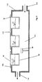
- the FIG. 2 shows an alternative embodiment of a support with which the sample vessels 50 can be tempered.
- the carrier is designed as a housing-like carrier 110 which encloses a cavity 114.
- tempered air by means of the air supply 116 can be fed.
- the tempered air flows through the cavity and leaves it through the air outlet 118.
- the associated temperature control unit for the air is not shown.
- the upper side 112 of the housing-like support 110 has openings through which the sample vessels 50 protrude into the cavity 114, so that the temperature control of the sample vessels 50 takes place directly through the air flowing through the cavity 114 of the housing-like support 110.
- the sample vessels here preferably each have a collar, which rest on the upper side 112 of the housing-like carrier 110.
- the at least one sample vessel (which in this case can also be quite large) is placed directly on the bottom of the housing, which then serves as a carrier.
- the temperature of the sample vessel is then via the ambient air within the housing, the temperature is adjusted by means of a temperature control device. This can be done by means of an external tempering device (similar to the embodiment of the FIG. 2 ) or by means of heating, cooling or heat exchanger elements inside the housing.
- a temperature sensor namely the second temperature sensor 34, whose output is connected to the temperature control device, so that a control loop - here called second control loop - results.
- the air of the measuring chamber - i. the air within the light-tight housing 40 above the carrier 10, 110 - generally has a temperature different from that of the carrier 10, 110 (except in the second alternative embodiment mentioned above) and generally between the temperature of the carrier 10 and 10 the ambient air of the laboratory is located.
- This air temperature within the housing 22 may be higher or lower than the temperature of the wearer.
- it is important to know this temperature which is why a temperature sensor - here called the third temperature sensor - is present, which measures this air temperature.
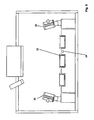
- This third temperature sensor 36 is preferably arranged relatively close to the carrier 10, 110 and above the carrier 10, 110. It is also important to know the humidity inside the housing, which is why an air humidity sensor 38, preferably in the vicinity of the third temperature sensor 36, is provided.
- the temperature of the sample vessels closing lid 52 including at least one other temperature sensor - here called the first temperature sensor 32 - is present.
- This first temperature sensor 32 is in contact with a lid 52. If only the temperature of a lid 52 is measured, make sure that is measured on a lid with a suitable position. This will be discussed in more detail later.
- the lid 52 are usually made of a very thin material such as glass or plastic, so that it is generally assumed that the temperature of the lid is almost homogeneous. Unless this is ensured, in individual applications it may be necessary to measure the temperature of a cover 52 both from the outside (as shown) and from the inside (not shown).
- the aim of the present invention is to create a possibility that the camera 42 (ie in general the optical sensor unit) always sees the plants or seedlings in the sample vessels 50 under the same conditions. These desired same conditions can be affected by condensation on the covers 52. Depending on the given conditions, this can happen both from the outside and from the inside.
- the ventilation device 20 (see FIGS. 1 and 3 ) intended.
- This ventilation device 20 has a housing 22, preferably with a plurality of passage openings 24. In each of these passage openings 24, a fan 26 and a heating coil 28 is provided.
- the ventilation device 28 has substantially the width of the carrier 10, 110, so that an air flow generated by the ventilation device 20 substantially meets or overflows all the covers 52.
- an air guide 23 may be provided.
- the passage openings 24 - and thus also the Air outlets of the ventilation device - lie above the support 10.
- the air flow generated by the ventilation device is directed obliquely from above on the tops of the lid. All other sides of the sample containers are not touched.
- the ventilation device 20 must not be in the field of vision of the camera 42 and not in the light path of the excitation light source 46 and is therefore arranged next to the carrier 10. It can be arranged directly on the carrier 10, on a separate holding block 21 (as shown) or on the inside of the light-tight housing 40. In general, it is preferable that the ventilation device 20 is pointing downwards and it is more preferable in that the angle of inclination is adjustable.
- the ventilation device 20 has the task to ensure that the temperature of the cover 52 is always above the dew point of both the ambient air (ie the air, which is located directly above the lids), as well as above the dew point of the air in the sample vessels.
- the temperature of the air flowing around the lid, coming from the ventilation device above the temperature of the sample vessel must be selected, otherwise at 100% relative humidity in the sample vessel, the moisture condenses on the lid from the inside.
- the temperature control it is sufficient to choose the temperature control so that the lid temperature does not drop below the ambient temperature in order to prevent condensation inside and outside.
- the sample vessel in a housing of the meter whose temperature is 23 ° C and in which there is a relative humidity of 50%.
- the carrier on which the sample containers, e.g. Petri dishes was set to 30 ° C and the temperature of the air in the Petri dishes above the plants had set to 29 ° C with a relative humidity of 100%.
- the inside temperature of the lid must be raised to> 30 ° C to prevent condensation.
- the dew point is 12 ° C, which is far from the assumed temperature of 23 ° C in the housing of the meter.
- sample containers can also be designed differently than the mentioned Petri dishes.
- micro-plates that is of plates with a plurality of wells, possible. In this case, each well forms a sample vessel.
Description
Die Erfindung betrifft eine Vorrichtung zur Anordnung wenigstens eines Probengefäßes in einem optischen Messgerät nach Anspruch 1, ein optisches Messgerät mit einer solchen Vorrichtung nach Anspruch 11 und die Verwendung eines solchen optischen Messgerätes nach Anspruch 14.The invention relates to a device for arranging at least one sample vessel in an optical measuring device according to claim 1, an optical measuring device having such a device according to claim 11 and the use of such an optical measuring device according to
Die gattungsbildende
In der biologischen und pharmazeutischen Forschung werden Fluoreszenz- und Lumineszenzmessverfahren seit vielen Jahren erfolgreich eingesetzt. Hierbei werden transfizierte oder transgene Tiere oder Pflanzen verwendet, wobei wenigstens ein Gen der betreffenden Pflanze oder des betreffenden Tieres ein Protein kodieren kann, das Lumineszenz oder Fluoreszenz zeigt. Ist dieses Gen aktiv, so wird dieses Protein gebildet und durch Beobachtung dessen Lumineszenz oder Fluoreszenz kann man Rückschlüsse auf die Aktivität des betreffenden Gens ziehen und somit weiterhin beispielsweise auf die Wirksamkeit bestimmter Substanzen auf das Tier/die Pflanze schließen. Die Messung der Lumineszenz- bzw. Fluoreszenzaktivität kann integral oder ortsaufgelöst durchgeführt werden.Fluorescence and luminescence measuring methods have been used successfully in biological and pharmaceutical research for many years. In this case, transfected or transgenic animals or plants are used, wherein at least one gene of the plant or animal in question can encode a protein showing luminescence or fluorescence. If this gene is active, this protein is formed and, by monitoring its luminescence or fluorescence, one can draw conclusions about the activity of the gene in question and thus, for example, further conclude the efficacy of certain substances on the animal / plant. The measurement of the luminescence or fluorescence activity can be carried out integrally or spatially resolved.
Insbesondere bei Pflanzen unterliegt die Expression vieler dieser zu untersuchenden Gene einem tageszeitlichen Rhythmus (circadianer Rhythmus) oder einer Abhängigkeit von Wachstumsphasen. Beides kann wiederum durch äußere Einflüsse natürlicher oder künstlicher Herkunft beeinflusst werden. Die Genexpressionen werden daher über längere Zeiträume (von Stunden bis zu mehreren Wochen) verfolgt.Particularly in the case of plants, the expression of many of these genes to be examined is subject to a circadian rhythm (circadian rhythm) or a dependence on growth phases. Both can in turn by external Influences of natural or artificial origin are influenced. Gene expression is therefore monitored over extended periods of time (from hours to several weeks).
Um das Probenmaterial, das heißt Pflanzen oder Keimlinge, vor ungewollten Kontaminationen frei zu halten, werden die Probengefäße, beispielsweise Petrischalen, zumindest verschlossen, manchmal auch sterilisiert und verschlossen. Dies geschieht üblicherweise mit transparenten Deckeln, die zusätzlich mit Klebeband oder Parafilm befestigt werden. Die Proben befinden sich im Probengefäß üblicherweise in beziehungsweise auf einem wässrigen Flüssig- oder Festmedium.In order to keep the sample material, ie plants or seedlings, free from unwanted contamination, the sample containers, for example Petri dishes, are at least closed, sometimes sterilized and sealed. This is usually done with transparent covers, which are additionally attached with tape or parafilm. The samples are usually located in the sample vessel in or on an aqueous liquid or solid medium.
Das wenigstens eine Probengefäß befindet sich auf einem Träger, welcher eine einfache Platte sein kann. Um, insbesondere bei mehreren Probengefäßen, immer dieselben Messpositionen zu haben, weist ein solcher Träger Vertiefungen oder ähnliches auf, so dass der Träger die geometrische Anordnung der Probengefäße bestimmt. Im folgenden wird der Einfachheit halber immer von mehreren Probengefäßen gesprochen, es ist jedoch klar, dass auch nur ein Probengefäß vorhanden sein kann.The at least one sample vessel is located on a carrier, which may be a simple plate. In order to always have the same measuring positions, in particular in the case of a plurality of sample vessels, such a carrier has depressions or the like, so that the carrier determines the geometric arrangement of the sample vessels. In the following, for the sake of simplicity, it is always referred to as multiple sample vessels, but it is clear that only one sample vessel can be present.
Die Messung der Lumineszenz oder Fluoreszenz erfolgt mittels einer optischen Sensoreinheit - zumeist ein Photomultipier oder eine empfindliche CCD-Kamera -, welche sich oberhalb des wenigstens einen Probengefäßes befindet.The measurement of the luminescence or fluorescence by means of an optical sensor unit - usually a photomultipier or a sensitive CCD camera - which is located above the at least one sample vessel.
Die vorliegende Erfindung stellt sich die Ausgabe, den Stand der Technik dahingehend zu verbessern, dass die Reproduzierbarkeit der Lumineszenz- oder Fluoreszenzmessungen verbessert wird.The present invention seeks to improve upon the prior art by improving the reproducibility of the luminescence or fluorescence measurements.
Es hat sich herausgestellt, dass es beim Betrieb des optischen Messgerätes zu einer Kondensatbildung an den Deckeln der Probengefäße kommen kann. Kondensation zu größeren Tröpfchen verfälscht durch Streuung und/oder Absorption die durchgeführt Messung (zumeist eine Fluoreszenz- oder Lumineszenzmessung; es kann sich aber auch um eine photographische Aufnahme handeln). Dies ist insbesondere bei Langzeitexperimenten, bei welchen ein Probengefäß oder ein Satz von Probengefäßen über mehrere Tage oder Wochen im optischen Messgerät verbleibt, aus mehreren Gründen sehr problematisch: Werden Lumineszenz- oder Fluoreszenzaufnahmen gemacht, so "sieht" die optische Sensoreinheit - insbesondere wenn sie ohne Ortsauflösung arbeitet - die entstandenen Kondensattröpfchen nicht. Von außen können diese auch nicht bemerkt werden, da bei Fluoreszenz- und Lumineszenzmessungen ein lichtdichtes Gehäuse vorhanden sein muss. Das heißt, dass die gesamte Messreihe wertlos sein kann und die Messzeit verloren ist. Noch schlimmer ist es, wenn das gebildete Kondensat durch Änderung der Bedingungnen, insbesondere der Temperatur, vor Beendigung der Messreihe wieder verdunstet. In diesem Fall kann dies unbemerkt bleiben und das verfälscht Messergebnis wird weiterverwendet.It has been found that, during operation of the optical measuring device, condensation may form on the lids of the sample vessels. Condensation into larger droplets is falsified by scattering and / or absorption of the measurement carried out (usually a fluorescence or luminescence measurement, but it can also be a photographic image). This is especially in long-term experiments in which a sample vessel or a set of sample vessels over several days or weeks in the optical measuring device remains very problematic for several reasons: If luminescence or fluorescence images are taken, the optical sensor unit "sees" - especially if it works without spatial resolution - the resulting condensate droplets not. From the outside, these can not be noticed because in fluorescence and Lumineszenzmessungen a light-tight housing must be present. This means that the entire measurement series can be worthless and the measurement time is lost. It is even worse if the formed condensate evaporates again by changing the conditions, in particular the temperature, before the end of the measurement series. In this case, this may go unnoticed and the corrupted measurement result will continue to be used.
Es ist deshalb eine Ventilatianseinrichtung mit einem Heizelement vorgesehen. Diese Ventilationseinrichtung ist so angeordnet, dass sie einen auf die Deckel gerichteten oder diese überstreichenden, erwärmten Luftstrom erzeugen und somit die Deckel erwärmen kann, wodurch eine Kondensatbildung auf den Außenseiten oder den Innenseiten der Deckel der Probengefäße verhindert wird.It is therefore a Ventilatianseinrichtung provided with a heating element. This ventilation means is arranged to produce a heated air flow directed towards or over the covers and thus to heat the covers, thereby preventing condensation on the outside or inside of the tops of the sample vessels.
Erfindungsgemäß ist ein Regelkreis zur Ansteuerung der Ventilationseinrichtung vorgesehen. Dieser ist vorzugsweise so eingestellt, dass die Erwärmung der Dekkel durch die Ventilationseinrichtung nur gerade so groß ist, dass die Temperatur der Deckel immer größer als der Taupunkt der Luft in den Probegefäßen und immer größer als der Taupunkt der Luft außerhalb der Probengefäße ist.According to the invention, a control circuit for controlling the ventilation device is provided. This is preferably set so that the heating of the lid by the ventilation device is just just so great that the temperature of the lid is always greater than the dew point of the air in the sample vessels and always greater than the dew point of the air outside the sample vessels.
Vorzugsweise ist der Träger temperierbar, so dass über den Träger die Probengefäße und somit die Pflanzen/Keimlinge kontrolliert temperiert und somit Umweltbedingungen simuliert werden können.Preferably, the support is temperature-controlled, so that the sample vessels and thus the plants / seedlings can be controlled in a controlled manner via the support and thus environmental conditions can be simulated.
Unter welchen Bedingungen eine Kondensation an einem Körper bei umgebender Luft stattfindet, kann den bekannten Taupunktkurven entnommen werden. Als Taupunkt oder Taupunkttemperatur bezeichnet man die Temperatur, bei der sich auf einen Gegenstand (bei gegebener Feuchte) ein Gieichgewichtszustand von kondensierendem und verdunstendem Wasser einstellt, mit anderen Worten, die Kondensatbildung gerade einsetzt. Die relative Feuchte in der Luft ist bei gegebenem Druck von der Temperatur abhängig. Luft, die nicht vollständig mit Wasserdampf gesättigt ist, hat eine relative Feuchte kleiner als 100% und kann bei unveränderter Temperatur weiteren Wasserdampf aufnehmen. Nimmt die Temperatur ab, nimmt auch die Aufnahmefähigkeit der Luft für Wasserdampf ab, das heißt, bei gegebener Feuchte steigt die relative Feuchte an. Beim Taupunkt ist eine relative Feuchte von 100% erreicht, es kommt zur Kondensation. Dabei bildet sich auf festen oder flüssigen Grenzflächen ein Niederschlag, der Effekt ist stärker, je geringer die Temperatur der Grenzflächen beziehungsweise je höher die Luftfeuchte ist. Die Abhängigkeit des Taupunktes von Temperatur und relativer Luftfeuchte kann den bekannten Taupunktkurven entnommen werden.Under what conditions a condensation takes place on a body in ambient air, the known dew point curves can be taken. The dew point or dew point temperature is the temperature at which on a subject (for a given humidity) sets a Gieichgewichtszustand of condensing and evaporating water, in other words, the condensation is just beginning. The relative humidity in the air at a given pressure depends on the temperature. Air that is not completely saturated with water vapor has a relative humidity of less than 100% and can absorb further water vapor at the same temperature. If the temperature decreases, the absorption capacity of the air for water vapor also decreases, ie for a given humidity the relative humidity increases. At the dew point a relative humidity of 100% is reached, condensation occurs. In this case, a precipitate forms on solid or liquid interfaces, the effect is stronger, the lower the temperature of the interfaces or the higher the humidity. The dependence of the dew point on temperature and relative humidity can be taken from the known dew point curves.
Um die Kondensation an den Deckeln der Probenträger zu verhindern, werden die Deckel mit temperierter Luft umströmt, die so gewählt wird, dass bei gegebener relativer Feuchte der umgebenden Luft innen oder außen die Temperatur des Deckels immer ausreichend oberhalb des Taupunktes liegt. Allerdings liegen innerhalb und außerhalb der Petrischale unterschiedliche Bedingungen vor. Man muss beachten, dass die Pflanzen selbst in einem wässrigen Flüssig- oder Festmedium eingebracht sind und hier möglicherweise eine bis zu 100% relative Luftfeuchte vorhanden sein könnte, während diese im Außenraum in einem Gehäuse des Messgerätes im allgemeinen viel niedriger ist. Der höhere Taupunkt legt die minimale Temperatur des Deckels fest, die ausreichend oberhalb dieses Taupunktes liegen muß, damit weder innen noch aussen eine Kondensation entstehen kann.In order to prevent the condensation on the lids of the sample carrier, the lids are surrounded by tempered air, which is selected such that, given the relative humidity of the surrounding air inside or outside, the temperature of the lid is always sufficiently above the dew point. However, there are different conditions inside and outside the Petri dish. It should be noted that the plants themselves are introduced into an aqueous liquid or solid medium and possibly up to 100% relative humidity could be present, while it is generally much lower in the outer space in a housing of the meter. The higher dew point determines the minimum temperature of the lid, which must be sufficiently above this dew point, so that neither inside nor outside condensation can occur.
Als Beispiel nehmen wir an, die Temperatur im einem Gehäuse des Messgerätes sei 30°C, die relative Feuchte der Luft 50%, die Temperatur des Trägers, auf welcher sich die Petrischalen befinden, sei 10°C, die Temperatur der Luft in der Petrischale oberhalb der Pflanzen sei 12°C und die relative Feuchte 90%. Nach der obigen Grafik beträgt der Taupunkt im Außenraum der Petrischale 18°C und der Taupunkt im Innenraum 11°C. Wenn die Abdeckung der Petrischale immer auf einer Temperatur größer als 18°C gehalten wird, kann es von außen keine Kondensation geben und von innen erst recht nicht.As an example, suppose that the temperature in a housing of the measuring instrument is 30 ° C, the relative humidity of the air is 50%, the temperature of the carrier on which the Petri dishes are located is 10 ° C, the temperature of the air in the Petri dish above the plants is 12 ° C and the
Die Temperatur des von der Ventilationseinrichtung erzeugten Luftstroms wird so geregelt, dass die obige Bedingung bezüglich der Taupunkte eingehalten wird.The temperature of the air flow generated by the ventilation device is controlled so as to comply with the above dew point condition.
Die Temperatur der Deckel wird mit einem an repräsentativer Stelle angebrachten Temperaturfühler erfasst und in einem ersten Regelkreis als Istwert verwendet und ständig mit dem Sollwert verglichen. Bei Abweichungen wird die Temperatur mittels der Ventilationseinrichtung entsprechend nachgeregelt.The temperature of the lid is detected with a temperature sensor attached to a representative point and used in a first control loop as an actual value and constantly compared with the target value. In case of deviations, the temperature is readjusted accordingly by means of the ventilation device.
Die Erfindung wird nun anhand eines Ausführungsbeispiels mit Bezug auf die Figuren näher erläutert. Hierbei zeigen:
- Figur 1
- einen schematisierten Querschnitt durch ein optisches Messgerät mit einer erfindungsgemäßen Vorrichtung zur Anordnung von Probengefäßen,
- Figur 2
- einen alternativen Träger mit Temperierungseinrichtung,
- Figur 3
- eine Draufsicht auf die Ventilationseinrichtung in
Figur 1 aus Richtung R, - Figur 4
- ein Diagramm, in welchem Taupunktlinien bei unterschiedlichen Temperaturen und Luftfeuchtigkeiten eingezeigt sind,
- Figur 5
- ein zweites Ausführungsbeispiel der Erfindung in einer der
Figur 1 entsprechenden Darstellung und - Figur 6
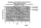
- ein Diagramm, welches die Abhängigkeit der relativen Luftfeuchte von der Temperatur zeigt.
- FIG. 1
- a schematic cross section through an optical measuring device with a device according to the invention for the arrangement of sample vessels,
- FIG. 2
- an alternative carrier with tempering device,
- FIG. 3
- a plan view of the ventilation device in
FIG. 1 from direction R, - FIG. 4
- a diagram in which dew point lines are shown at different temperatures and humidities,
- FIG. 5
- A second embodiment of the invention in one of
FIG. 1 corresponding representation and - FIG. 6
- a diagram showing the dependence of the relative humidity of the temperature.
Die
Die Probengefäße 50 sind auf einem Träger 10 angeordnet, welcher für jedes Probengefäß eine Vertiefung 12 aufweist. Der Träger 10 besteht im gezeigten Ausführungsbeispiel aus Metall, insbesondere aus Aluminium, und hat eine entsprechend hohe Wärmeleitfähigkeit. Oberhalb des Trägers 10 ist ein optisches Messinstrument, hier in Form einer Kamera, insbesondere einer CCD-Kamera 42 angeordnet, welche nach unten blickt Vor dem Eintrittsfenster dieser Kamera 42 ist ein Emissionsfilter 44 angeordnet, welches nur Licht einer bestimmten Wellenlänge zur Kamera 42 durchlässt. Es ist weiterhin eine Anregungslichtquelle 46 vorhanden, welche in Richtung des Trägers 10 zeigt und in deren Strahlengang ein Anregungsfilter 48 vorhanden ist. Die Funktionsweise eines solchen Fluorometers ist grundsätzlich bekannt und muss hier nicht im Detail erläutert werden. Je nach gegebener Geometrie ist es zum einen möglich, dass die Kamera 42 alle Probengefäße 50 gleichzeitig sieht oder es kann eine relative Verschieblichkeit zwischen Träger 10 und Kamera 42 in horizontaler Richtung vorgesehen sein, so dass die Kamera jeweils nur ein Probengefäß 50 messen kann (nicht dargestellt). Dasselbe gilt für die Anregungslichtquelle 46: Diese kann entweder so ausgebildet sein, dass sie alle Probengefäße 50 gleichzeitig beleuchtet oder sie kann so ausgebildet sein, dass sie jeweils nur ein aktuell zu messendes Probengefäß beleuchtet, wobei in diesem Fall ebenfalls eine relative Beweglichkeit zwischen Anregungslichtquelle 46 und Träger 10 und/oder eine Verschwenkbarkeit der Anregungslichtquelle 46 gegeben sein muss. Träger 10, Eintrittsfenster der Kamera 42 und Austrittsfienster der Anregungslichtquelle 46 befinden sich in einem lichtdichten Gehäuse 40.The
Der Träger 10 ist temperierbar, damit man die Pflanzen/Keimlinge, welche sich in den Probengefäßen 50 befinden, bei unterschiedlichen und definierten Temperaturen beobachten kann. Die Temperierung des Trägers erfolgt im gezeigten Ausführungsbeispiel über einen Flüssigkeitskreislauf. Dieser weist innerhalb des Trägers 10 einen Wärmetauscher 14 und außerhalb des Trägers 10 ein Temperierungsgerät 16, mittels er die umgepumpte Flüssigkeit (zumeist Wasser) temperiert, das heißt in der Regel sowohl erwärmt als auch gekühlt, werden kann. Aufgrund der Vertiefungen 12 (welche im Durchmesser im Wesentlichen den Durchmessern der Probengefäße 50 entsprechen) nehmen nach einer gewissen Betriebsdauer die Probengefäße 50 im Wesentlichen die Temperatur des Trägers an. Hier zu beachten, dass in der schematischen Darstellung aufgrund besserer Übersichtlichkeit ein gewisser Abstand zwischen diesen Probengefäßen 50 und den Wandungen und der Vertiefungen 12 eingezeichnet ist, tatsächlich besteht natürlich unmittelbarer Kontakt zwischen dem Träger 10 und den Probengefäßen 50 zumindest über den Boden der Probengefäße 50. Auch der seitliche Freiraum ist vorzugsweise so klein wie möglich gehalten, um eine möglichst guten Wärmekontakt herzustellen. Dieser kann noch dadurch verbessert werden, dass ein flüssiges Medium in den Vertiefungen 12 vorgesehen ist, so dass sich keine Luftspalte ergeben. Anstatt einen Wärmetauscher vorzusehen, wäre es auch möglich eine direkte elektrische Temperierung des Trägers 10 vorzusehen, nämlich mittels wenigstens eines elektrischen Heizelements und wenigstens eines Peltierkühlers.The
Die
In einer weiteren alternativen Ausführungsform ist überhaupt kein separater Träger vorhanden, sondern das wenigstens eine Probengefäß (welches in diesem Fall auch recht groß sein kann), wird unmittelbar auf den Boden des Gehäuses gestellt, welcher dann als Träger dient. Die Temperierung des Probengefäßes erfolgt dann über die Umgebungsluft innerhalb des Gehäuses, deren Temperatur mittels einer Temperierungseinrichtung eingestellt wird. Dies kann mittels eines externen Temperierungsgerätes (ähnlich zur Ausführungsform der
Für das Weitere ist es ohne Bedeutung, wie der Träger konkret ausgebildet ist, ob also die Temperierung der Probengefäß 50 über direkten Kontakt mit einem massiven Träger oder über Luft erfolgt. Im folgenden wird deshalb allgemein immer von der Temperatur des Trägers oder von der Temperatur der Probengefäße gesprochen.For the rest, it is irrelevant how the carrier is concretely formed, ie whether the temperature control of the
Um die Temperatur des Trägers 10- und somit die der Probengefäße 50 - regeln zu können, ist ein Temperatursensor, nämlich der zweite Temperatursensor 34 vorgesehen, dessen Ausgang mit dem Temperierungsgerät verbunden ist, so dass sich ein Regelkreis - hier zweiter Regelkreis genannt - ergibt.In order to be able to regulate the temperature of the
Die Luft der Messkammer - d.h. die Luft innerhalb des lichtdichten Gehäuses 40 oberhalb des Trägers 10, 110 - hat im Allgemeinen eine Temperatur, welche von der des Trägers 10, 110 verschieden ist (außer bei der oben genannten zweiten alternativen Ausführungsform) und im Allgemeinen zwischen der Temperatur des Trägers 10 und der Umgebungsluft des Labors liegt. Diese Lufttemperatur innerhalb des Gehäuses 22 kann höher oder niedriger als die Temperatur des Trägers sein. Für die hier gezeigte bevorzugte Ausführungsform ist es wichtig diese Temperatur zu kennen, weshalb ein Temperatursensor - hier dritter Temperatursensor genannt - vorhanden ist, welcher diese Lufttemperatur mißt. Dieser dritte Temperatursensor 36 ist vorzugsweise relativ nahe zum Träger 10, 110 und oberhalb des Trägers 10, 110 angeordnet. Es ist ebenfalls wichtig die Luftfeuchtigkeit innerhalb des Gehäuses zu kennen, weshalb ein Luftfeuchtesensor 38, vorzugsweise in der Nähe des dritten Temperatursensors 36, vorgesehen ist.The air of the measuring chamber - i. the air within the light-
Schließlich benötigt man noch die Temperatur der die Probengefäße verschließende Deckel 52, wozu wenigstens ein weiterer Temperatursensor - hier erster Temperatursensor 32 genannt - vorhanden ist. Dieser erste Temperatursensor 32 befindet sich in Kontakt zu einem Deckel 52. Sofern nur die Temperatur eines Deckels 52 gemessen wird, ist darauf zu achten, dass an einem Deckel mit geeigneter Position gemessen wird. Hierauf wird später noch genauer eingegangen werden. Die Deckel 52 bestehen in der Regel aus einem sehr dünnen Material wie Glas oder Kunststoff, so dass in der Regel davon auszugehen ist, dass die Temperatur des Deckels nahezu homogen ist. Sofern dies nicht sicher gestellt ist, kann es in einzelnen Anwendungsfällen notwendig sein, die Temperatur eines Deckels 52 sowohl von der Außenseite (wie dargestellt) als auch von der Innenseite (nicht dargestellt) zu messen.Finally, it still requires the temperature of the sample
Wie bereits erwähnt wurde, befinden sich in den Probengefäßen 50 Pflanzen oder Keimlinge (in
Ziel der vorliegenden Erfindung ist es, eine Möglichkeit zu schaffen, dass die Kamera 42 (also allgemein die optische Sensoreinheit) die Pflanzen oder Keimlinge in den Probengefäßen 50 immer zu gleichen Bedingungen sieht. Diese gewünschten gleichen Bedingungen können dadurch beeinträchtigt werden, dass sich an den Deckeln 52 Kondenswasser niederschlägt. Je nach gegebenen Bedingungen kann dies sowohl von Außen als auch von Innen her geschehen. Um eine solche Kondensatbildung zu verhindern, ist die Ventilationseinrichtung 20 (siehe
Die Ventilationseinrichtung 20 darf sich natürlich nicht im Blickfeld der Kamera 42 und nicht im Lichtpfad der Anregungslichtquelle 46 befinden und ist deshalb neben dem Träger 10 angeordnet. Sie kann direkt am Träger 10 angeordnet sein, an einem seperaten Halteblock 21 (wie dargestellt) oder auch an der Innenseite des lichtdichten Gehäuses 40. In der Regel ist es zu bevorzugen, dass die Ventilationseinrichtung 20 schräg nach unten zeigt und es ist weiter zu bevorzugen, dass der Neigungswinkel einstellbar ist.Of course, the
Die Ventilationseinrichtung 20 hat die Aufgabe dafür zu sorgen, dass die Temperatur der Deckel 52 stets über dem Taupunkt sowohl der Umgebungsluft (also der Luft, welche sich direkt über den Deckeln befindet), als auch über dem Taupunkt der Luft in den Probengefäßen liegt.The
Die entsprechenden Taupunkttemperaturen sind bekannt und anhand von Beispielen in
- Der erste Regelkreis besteht aus dem ersten Temperatursensor 32,
dem zweiten Temperatursensor 34,dem dritten Temperatursensor 36,dem Luftfeuchtesensor 38 und der Steuereinheit 30 für die Ventilationseinrichtung.Der erste Temperatursensor 32 mißt, wie oben bereits dargestellt, dieTemperatur der Deckel 52, in der Regel die Temperatur eines repräsentativen Deckels. Es sollte die Temperatur des Deckels gemessen werden, welcher tendenziell am kältesten ist, sich also beispielsweise - wie inFigur 1 dargestellt - am weitesten von der Ventilationseinrichtung weg befindet. Erfüllt dieser das notwendige Temperaturkriterium, so ist davon auszugehen, dass die übrigen Deckel dies auch tun. Es wird ständig die Lufttemperatur im Gehäuse mittels des dritten Temperatursensors 36 und die Luftfeuchte innerhalb des Gehäusesmit dem Luftfeuchtesensor 38 gemessen und daraus der Taupunkt der gemessenen Luft automatisch berechnet. Weiterhin wird permanent die Temperatur des Trägers 10 gemessen, von welcher auch angenommen wird, dass sie im Wesentlichen auch die Temperatur der Probengefäße ist, und mit der Annahme, dass die Luftfeuchtigkeit der Luft innerhalb derProbengefäße 100 % beträgt, wird der Taupunkt dieser Luft automatisch berechnet beziehungsweise geschätzt. Um eine höhere Genauigkeit erzielen zu können, wäre es (mit entsprechendem Mehraufwand) natürlich auch möglich, die Temperatur eines Probengefäßes oder direkt die Temperatur der Luft in einem Probengefäß zu messen. Meist reichen wie oben beschrieben geschätzte Werte für Lufttemperatur und Luftfeuchtigkeit im Probengefäß aus. Die Messungen werden permanent durchgeführt und die entsprechenden Berechnungen werden beispielsweise von einem Mikroprozessor oder der Software eines angeschlossenen Computers erledigt. Nähert sich die Temperatur des Deckels der höheren der beiden bestimmtenbeziehungsweise geschätzten Taupunktstemperaturen auf weniger als einen vorbestimmten Wert, beispielsweise 1°C, so steuert dieSteuereinheit 30, welcher die genannten Werte direkt oder indirekt zugeführt werden, die Ventilationseinrichtung an, beziehungsweise erhöht deren aktuelle Leistung durch eine größere Heizleistung und/oder einen größeren Luftdurchsatz. Übersteigt daraufhin die Temperatur des Deckels wieder einen bestimmten Wert, beispielsweise 2°C mehr als die höhere der beiden Taupunktstemperaturen, so schaltet die Steuereinheit die Ventilationseinrichtung wieder ab oder reduziert deren Leistung. Somit kann die Temperatur der Deckel in einem sehr schmalen Band gehalten werden, wodurch einerseits zuverlässig eine Kondensatbildung verhindert wird und andererseits die Heizleistung und der Temperaturunterschied zwischen Deckel und Probengefäß so gering wie möglich gehalten werden.
- The first control circuit consists of the
first temperature sensor 32, thesecond temperature sensor 34, thethird temperature sensor 36, thehumidity sensor 38 and thecontrol unit 30 for the ventilation device. As already indicated above, thefirst temperature sensor 32 measures the temperature of thecover 52, as a rule the temperature of a representative cover. It should be the temperature of the lid to be measured, which tends to be the coldest, so for example - as inFIG. 1 shown - furthest away from the ventilation device. If this fulfills the necessary temperature criterion, then it can be assumed that the other lids do so. It is constantly the air temperature in the housing by means of thethird temperature sensor 36 and the humidity measured within the housing with thehumidity sensor 38 and calculated from the dew point of the measured air automatically. Furthermore, the temperature of thecarrier 10, which is also believed to be substantially the temperature of the sample vessels, is constantly measured, and assuming that the humidity of the air within the sample vessels is 100%, the dew point of this air becomes automatic calculated or estimated. In order to achieve a higher accuracy, it would of course also be possible (with corresponding additional effort) to measure the temperature of a sample vessel or directly the temperature of the air in a sample vessel. Usually estimated values for air temperature and humidity in the sample vessel are sufficient as described above. The measurements are performed permanently and the corresponding calculations are done, for example, by a microprocessor or the software of a connected computer. When the temperature of the lid of the higher of the two specific dew point temperatures approaches less than a predetermined value, for example 1 ° C, thecontrol unit 30, to which the above values are directly or indirectly supplied, controls the ventilator or increases its actual output by a larger heating power and / or a larger air flow. Then the temperature of the lid again exceeds a certain value, for example 2 ° C more than the higher of the two dew point temperatures, the control unit shuts off the ventilation device or reduces its power. Thus, the temperature of the lid can be kept in a very narrow band, which on the one hand reliable condensate formation is prevented and on the other hand, the heating power and the temperature difference between the lid and sample vessel are kept as low as possible.
Es kann vorteilhaft sein, die Ventilatoren permanent laufen zu lassen und über den beschriebenen Regelkreis nur die Heizwendel anzusteuern.It may be advantageous to run the fans permanently and to control only the heating coil via the described control loop.
Der physikalische Hintergrund der Erfindung wird besser verständlich, wenn man sich mit Hilfe der Gleichung eines idealen Gases die Abhängigkeit der relativen Luftfeuchte von der Temperatur veranschaulicht. Man erkennt, dass im Bereich der Wasserdampfsättigung, d.h. einer relativen Luftfeucht von 100%, bereits kleinste Temperaturänderungen die relative Feuchte um mehrere Prozent ändern. Im Beispiel der
Es sind nun 2 Fälle zu unterscheiden:
- a) Die Temperatur des Probengefäßes wird relativ zu der Umgebungstemperatur angehoben.
- b) Die Temperatur des Probengefäßes wird relativ zu der Umgebungstemperatur abgesenkt.
- a) The temperature of the sample vessel is raised relative to the ambient temperature.
- b) The temperature of the sample vessel is lowered relative to the ambient temperature.
Im ersten Fall muss die Temperierung der den Deckel umströmenden, von der Ventilationseinrichtung kommenden Luft oberhalb der Temperatur des Probengefäßes gewählt werden, da sonst bei 100%-iger relativer Luftfeuchte im Probengefäß die Feuchtigkeit am Deckel von innen kondensiert.In the first case, the temperature of the air flowing around the lid, coming from the ventilation device above the temperature of the sample vessel must be selected, otherwise at 100% relative humidity in the sample vessel, the moisture condenses on the lid from the inside.
Im zweiten Fall reicht es aus, die Temperierung so zu wählen, dass die Deckeltemperatur nicht unter die Umgebungstemperatur absinkt, um innen und außen Kondensation zu verhindern.In the second case, it is sufficient to choose the temperature control so that the lid temperature does not drop below the ambient temperature in order to prevent condensation inside and outside.
Als Beispiel für den ersten Fall befinde sich das Probengefäß in einem Gehäuse des Messgerätes, dessen Temperatur bei 23°C liege und in dem eine relative Luftfeuchte von 50% herrsche. Der Träger, auf welchem sich die Probengefäße, z.B. Petrischalen befinden, sei auf 30°C gesetzt und die Temperatur der Luft in den Petrischalen oberhalb der Pflanzen habe sich auf 29°C eingestellt mit einer relativen Feuchte von 100%. Nach zuvor Gesagtem muss nun die Deckelinnentemperatur auf >30°C gehoben werden, um Kondensation zu vermeiden.As an example of the first case is the sample vessel in a housing of the meter, whose temperature is 23 ° C and in which there is a relative humidity of 50%. The carrier on which the sample containers, e.g. Petri dishes was set to 30 ° C and the temperature of the air in the Petri dishes above the plants had set to 29 ° C with a relative humidity of 100%. After what has been said before, the inside temperature of the lid must be raised to> 30 ° C to prevent condensation.
Im Außenraum liegt der Taupunkt bei 12°C, was weit weg ist von der angenommenen Temperatur von 23°C im Gehäuse des Messgerätes.In the outdoor area, the dew point is 12 ° C, which is far from the assumed temperature of 23 ° C in the housing of the meter.
Wie in
Die Erfindung wurde mit Bezug auf die Messung von Pflanzen und Keimlingen erläutert, jedoch können auch Messungen an anderen Organismen, wie insbesondere Bakterien, Kleintieren oder Embryonen und Zellkulturen durchgeführt werden. Weiterhin können die Probengefäße auch anders als die erwähnten Petrischalen ausgebildet sein. Insbesondere ist auch der Einsatz von sogenannten Mikroplatten, das heißt von Platten mit einer Vielzahl von Vertiefungen, möglich. In diesem Fall bildet jede Vertiefung ein Probengefäß.The invention has been explained with reference to the measurement of plants and seedlings, but measurements on other organisms, in particular bacteria, small animals or embryos and cell cultures can also be carried out. Furthermore, the sample containers can also be designed differently than the mentioned Petri dishes. In particular, the use of so-called micro-plates, that is of plates with a plurality of wells, possible. In this case, each well forms a sample vessel.
- 1010
- Trägercarrier
- 1212
- Vertiefungdeepening
- 1414
- Wärmetauscherheat exchangers
- 1818
- TemperierungsgerätTemperierungsgerät
- 2020
- Ventilationseinrichtungventilation device
- 2121
- Halteblockholding block
- 2323
- Luftleitelementair guide
- 2424
- DurchgangsöffnungThrough opening
- 2626
- Ventilatorfan
- 2828
- Heizwendelheating coil
- 3030
- Steuereinheit der VentilationseinrichtungControl unit of the ventilation device
- 3232
- erster Temperatursensorfirst temperature sensor
- 3434
- zweiter Temperatursensorsecond temperature sensor
- 3636
- dritter Temperatursensorthird temperature sensor
- 3838
- LuftfeuchtesensorHumidity Sensor
- 4040
- lichtdichtes Gehäuselight-tight housing
- 4242
- Kameracamera
- 4444
- Emissionsfilteremission filter
- 4646
- AnregungslichtquelleExcitation light source
- 4848
- Anregungsfilterexcitation filter
- 5050
- Probengefäßsample vessel
- 50a50a
- Kragencollar
- 5252
- Deckelcover
- 110110
- gehäuseartiger Trägerboxy carrier
- 112112
- Oberseitetop
- 114114
- Hohlraumcavity
- 116116
- Luftzufuhrair supply
- 118118
- Luftauslassair outlet
Claims (14)
- Device for assembling at least one sample container (50) in an optical measuring device, with
a carrier (10, 110) for arranging the at least one sample container (50),
wherein at least one ventilation device (20) is provided on the carrier (10, 110) or next to the carrier (10, 110) with at least one air outlet arranged above the carrier (10, 110), wherein the ventilation device (20) has a heating element (28) for heating the air flow which it can generate,
characterised in that at least one first temperature sensor (32) is provided for measuring the temperature of a transparent cover (52) closing a sample container (50), wherein this first temperature sensor (32) is part of a first control circuit which controls at least the heating element of the ventilation device (20). - Device according to claim 1, characterised in that in addition to the ventilation device (20), a tempering device is provided for tempering the at least one sample container (50).
- Device according to claim 2, characterised in that the carrier (10, 110) is equipped with or thermally connected with the tempering device.
- Device according to claim 2 or claim 3, characterised in that the tempering device allows both a heating and a cooling of the sample container in relation to the ambient temperature.
- Device according to any one of claims 2 to 4, characterised in that a second temperature sensor (34) is provided for measuring the temperature inside the sample container, that of the sample container or the carrier, wherein this second temperature sensor (34) is part of a first control circuit which controls at least the heating element of the ventilation device.
- Device according to claim 1 and/or claim 5, characterised in that the first control circuit is configured such that, because of the air flow which can be supplied by the ventilation device, the temperature of the cover (52) always lies above the dew point of the air present inside the sample container.
- Device according to claim 5 or claim 6, characterised in that the second temperature sensor (34) is also part of a second circuit which controls the tempering device.
- Device according to claim 6 or claim 7, characterised in that a third temperature sensor is arranged above the carrier (10, 110) and is part of the first control circuit, wherein the first control circuit is configured such that, because of the air flow which can be supplied by the ventilation device, the temperature of the cover (52) always lies above the dew point of the air measured by the third temperature sensor (36).
- Device according to claim 8, characterised in that an air humidity sensor (38) is provided above the carrier (10, 110) for measuring the relative humidity, wherein this air humidity sensor is part of the first control circuit.
- Device according to any one of the preceding claims, characterised in that at least two ventilation devices (20, 20) according to claim 1 are provided.
- Optical measuring device with a device according to any one of claims 1 to 10 and an optical sensor unit, the inlet window of which lies above the carrier.
- Optical measuring device according to claim 11, characterised in that the carrier and ventilation device are arranged inside a light-impermeable housing (40).
- Optical measuring device according to any one of claims 11 or 12, characterised in that it is a luminometer and/or fluorometer.
- Use of an optical measuring device according to any one of claims 11 to 13 for observing at least one organism in at least one sample container.
Priority Applications (2)
| Application Number | Priority Date | Filing Date | Title |
|---|---|---|---|
| EP10008445.8A EP2418472B1 (en) | 2010-08-13 | 2010-08-13 | Device for assembling at least one sample container in an optical measuring device, optical measuring device with such a device and use of such an optical measuring device |
| US13/025,574 US8393234B2 (en) | 2010-08-13 | 2011-02-11 | Apparatus, device and method for arranging at least one sample container |
Applications Claiming Priority (1)
| Application Number | Priority Date | Filing Date | Title |
|---|---|---|---|
| EP10008445.8A EP2418472B1 (en) | 2010-08-13 | 2010-08-13 | Device for assembling at least one sample container in an optical measuring device, optical measuring device with such a device and use of such an optical measuring device |
Publications (2)
| Publication Number | Publication Date |
|---|---|
| EP2418472A1 EP2418472A1 (en) | 2012-02-15 |
| EP2418472B1 true EP2418472B1 (en) | 2013-08-07 |
Family
ID=43397511
Family Applications (1)
| Application Number | Title | Priority Date | Filing Date |
|---|---|---|---|
| EP10008445.8A Active EP2418472B1 (en) | 2010-08-13 | 2010-08-13 | Device for assembling at least one sample container in an optical measuring device, optical measuring device with such a device and use of such an optical measuring device |
Country Status (2)
| Country | Link |
|---|---|
| US (1) | US8393234B2 (en) |
| EP (1) | EP2418472B1 (en) |
Families Citing this family (8)
| Publication number | Priority date | Publication date | Assignee | Title |
|---|---|---|---|---|
| CN102252955A (en) * | 2010-05-21 | 2011-11-23 | 鸿富锦精密工业(深圳)有限公司 | Constant temperature and constant humidity cabinet |
| US10054558B2 (en) * | 2013-12-27 | 2018-08-21 | Owens-Brockway Glass Container Inc. | System and method for testing thermal properties of a container |
| AT516382B1 (en) * | 2015-03-13 | 2016-05-15 | Anton Paar Gmbh | Conditioning a sample container by means of conditioning fluid for promoting heat coupling and suppressing fogging |
| DE102015214414B4 (en) * | 2015-07-29 | 2020-10-22 | Berthold Technologies Gmbh & Co. Kg | Method and system for determining biological properties of samples |
| WO2019060375A1 (en) | 2017-09-19 | 2019-03-28 | Beckman Coulter, Inc. | System for analog light measuring and photon counting in chemiluminescence measurements |
| US11655992B2 (en) * | 2018-02-13 | 2023-05-23 | Advanced Semiconductor Engineering, Inc. | Measuring system |
| US11713614B2 (en) * | 2019-01-11 | 2023-08-01 | Sp Technology Co., Ltd. | Condensation prevention type transmission window for CMS module test chamber |
| CN117286022B (en) * | 2023-11-22 | 2024-02-20 | 中国农业科学院农业环境与可持续发展研究所 | Contrast experimental device for microorganisms in soil |
Family Cites Families (12)
| Publication number | Priority date | Publication date | Assignee | Title |
|---|---|---|---|---|
| DE4200001A1 (en) * | 1992-01-01 | 1993-07-08 | Robert Prof Dr Ing Massen | OPTICAL CLASSIFICATION OF PLANTS |
| FR2806583B1 (en) * | 2000-03-21 | 2002-06-14 | Hubert Capelle | METHOD AND INSTALLATION FOR FORCING ENDIVES |
| US20020100582A1 (en) * | 2000-09-05 | 2002-08-01 | Oldenburg Kevin R. | Rapid thermal cycling device |
| ATE337092T1 (en) * | 2003-09-23 | 2006-09-15 | Evotec Technologies Gmbh | CLIMATE CHAMBER FOR MICROSCOPES |
| EP1711590B1 (en) * | 2004-01-08 | 2016-12-14 | Dako Denmark A/S | Apparatus and methods for processing biological samples and a reservoir therefore |
| EP1730666A1 (en) * | 2004-03-29 | 2006-12-13 | André Hoffmann | Identification, verification, and recognition method and system |
| JP2007334141A (en) * | 2006-06-16 | 2007-12-27 | Sanyo Electric Co Ltd | Culture observation system |
| DE102006043117B3 (en) * | 2006-09-08 | 2008-04-10 | Yara International Asa | Provision of necessary water and nutrients for cultured and horticulture plants, involves ensuring optimum supply of water and nutrients to plants based on control value from evaluation and signal processing unit |
| US7497136B2 (en) * | 2006-12-13 | 2009-03-03 | Espec Corp. | Environmental test apparatus |
| DE102007015826A1 (en) * | 2007-03-30 | 2008-10-02 | TRüTZSCHLER GMBH & CO. KG | Device on a textile machine, in particular spinning preparation machine, for cooling of heat-emitting electrical components |
| US20090025287A1 (en) * | 2007-07-25 | 2009-01-29 | Yu Mei Lee | Plant growing system |
| US20090310839A1 (en) * | 2008-06-11 | 2009-12-17 | Katzenelson Omer Y | Systems and methods to perform inhibition diagnostic testing |
-
2010
- 2010-08-13 EP EP10008445.8A patent/EP2418472B1/en active Active
-
2011
- 2011-02-11 US US13/025,574 patent/US8393234B2/en active Active
Also Published As
| Publication number | Publication date |
|---|---|
| EP2418472A1 (en) | 2012-02-15 |
| US20120036918A1 (en) | 2012-02-16 |
| US8393234B2 (en) | 2013-03-12 |
Similar Documents
| Publication | Publication Date | Title |
|---|---|---|
| EP2418472B1 (en) | Device for assembling at least one sample container in an optical measuring device, optical measuring device with such a device and use of such an optical measuring device | |
| EP2848679B1 (en) | Laboratory incubator with humidity adjustment | |
| EP1575706B1 (en) | Climatic chamber for microscopes | |
| EP1673609B1 (en) | Device and method for handling a probe | |
| DE2639857C2 (en) | Device for studying the properties and breeding behavior of living organisms | |
| DE20220550U1 (en) | Air-conditioned storage cabinet | |
| DE102006034534B4 (en) | Arrangement for temperature control of the sample space on a microscope | |
| EP3175279B1 (en) | Light microscope having a sample stage for cryomicroscopy | |
| AT522439B1 (en) | Incubator for biological material | |
| DE2328637C3 (en) | ||
| DE10259251B4 (en) | Cultivation chamber on a microscope rack | |
| DE1482286A1 (en) | Climate chambers and their applications | |
| EP1768782B1 (en) | Cooling device for biological samples | |
| DE202020105990U1 (en) | Parasite in-vitro breeding facility that enables real-time image recording | |
| EP3377604B1 (en) | System for growing and reproducing microorganisms | |
| WO2004033616A1 (en) | Device for culturing cells, particularly human or animal cells | |
| DE102016222363A1 (en) | Monitoring device for controlling chemical reactions by means of MR measurements in a flow cell | |
| DE602004007732T2 (en) | A liquid chromatography | |
| CH650020A5 (en) | APPARATUS FOR STEAM STERLIZATION OF FERMENTATION OBJECTS. | |
| DE102020120790B4 (en) | Inverted microscope with incubation space and temperature sensor | |
| EP3444329B1 (en) | Device for the humidification of a gas mixture for cell incubation | |
| AT516382B1 (en) | Conditioning a sample container by means of conditioning fluid for promoting heat coupling and suppressing fogging | |
| EP0949526A2 (en) | Cuvette à débordement contrÔlé en température pour échantillons biologiques | |
| DE102019201023A1 (en) | Plant growth chamber | |
| EP4083183A1 (en) | Cell culture incubator |
Legal Events
| Date | Code | Title | Description |
|---|---|---|---|
| 17P | Request for examination filed |
Effective date: 20110715 |
|
| AK | Designated contracting states |
Kind code of ref document: A1 Designated state(s): AL AT BE BG CH CY CZ DE DK EE ES FI FR GB GR HR HU IE IS IT LI LT LU LV MC MK MT NL NO PL PT RO SE SI SK SM TR |
|
| AX | Request for extension of the european patent |
Extension state: BA ME RS |
|
| PUAI | Public reference made under article 153(3) epc to a published international application that has entered the european phase |
Free format text: ORIGINAL CODE: 0009012 |
|
| GRAP | Despatch of communication of intention to grant a patent |
Free format text: ORIGINAL CODE: EPIDOSNIGR1 |
|
| RIC1 | Information provided on ipc code assigned before grant |
Ipc: G01N 21/03 20060101AFI20130405BHEP |
|
| INTG | Intention to grant announced |
Effective date: 20130423 |
|
| GRAS | Grant fee paid |
Free format text: ORIGINAL CODE: EPIDOSNIGR3 |
|
| GRAA | (expected) grant |
Free format text: ORIGINAL CODE: 0009210 |
|
| AK | Designated contracting states |
Kind code of ref document: B1 Designated state(s): AL AT BE BG CH CY CZ DE DK EE ES FI FR GB GR HR HU IE IS IT LI LT LU LV MC MK MT NL NO PL PT RO SE SI SK SM TR |
|
| REG | Reference to a national code |
Ref country code: GB Ref legal event code: FG4D Free format text: NOT ENGLISH |
|
| REG | Reference to a national code |
Ref country code: CH Ref legal event code: EP Ref country code: AT Ref legal event code: REF Ref document number: 625965 Country of ref document: AT Kind code of ref document: T Effective date: 20130815 |
|
| REG | Reference to a national code |
Ref country code: IE Ref legal event code: FG4D Free format text: LANGUAGE OF EP DOCUMENT: GERMAN |
|
| REG | Reference to a national code |
Ref country code: DE Ref legal event code: R096 Ref document number: 502010004259 Country of ref document: DE Effective date: 20131002 |
|
| REG | Reference to a national code |
Ref country code: NL Ref legal event code: VDEP Effective date: 20130807 |
|
| REG | Reference to a national code |
Ref country code: LT Ref legal event code: MG4D |
|
| PG25 | Lapsed in a contracting state [announced via postgrant information from national office to epo] |
Ref country code: LT Free format text: LAPSE BECAUSE OF FAILURE TO SUBMIT A TRANSLATION OF THE DESCRIPTION OR TO PAY THE FEE WITHIN THE PRESCRIBED TIME-LIMIT Effective date: 20130807 Ref country code: SE Free format text: LAPSE BECAUSE OF FAILURE TO SUBMIT A TRANSLATION OF THE DESCRIPTION OR TO PAY THE FEE WITHIN THE PRESCRIBED TIME-LIMIT Effective date: 20130807 Ref country code: IS Free format text: LAPSE BECAUSE OF FAILURE TO SUBMIT A TRANSLATION OF THE DESCRIPTION OR TO PAY THE FEE WITHIN THE PRESCRIBED TIME-LIMIT Effective date: 20131207 Ref country code: HR Free format text: LAPSE BECAUSE OF FAILURE TO SUBMIT A TRANSLATION OF THE DESCRIPTION OR TO PAY THE FEE WITHIN THE PRESCRIBED TIME-LIMIT Effective date: 20130807 Ref country code: NO Free format text: LAPSE BECAUSE OF FAILURE TO SUBMIT A TRANSLATION OF THE DESCRIPTION OR TO PAY THE FEE WITHIN THE PRESCRIBED TIME-LIMIT Effective date: 20131107 Ref country code: CY Free format text: LAPSE BECAUSE OF FAILURE TO SUBMIT A TRANSLATION OF THE DESCRIPTION OR TO PAY THE FEE WITHIN THE PRESCRIBED TIME-LIMIT Effective date: 20130814 Ref country code: PT Free format text: LAPSE BECAUSE OF FAILURE TO SUBMIT A TRANSLATION OF THE DESCRIPTION OR TO PAY THE FEE WITHIN THE PRESCRIBED TIME-LIMIT Effective date: 20131209 |
|
| BERE | Be: lapsed |
Owner name: BERTHOLD TECHNOLOGIES G.M.B.H. & CO. KG Effective date: 20130831 |
|
| PG25 | Lapsed in a contracting state [announced via postgrant information from national office to epo] |
Ref country code: SI Free format text: LAPSE BECAUSE OF FAILURE TO SUBMIT A TRANSLATION OF THE DESCRIPTION OR TO PAY THE FEE WITHIN THE PRESCRIBED TIME-LIMIT Effective date: 20130807 Ref country code: FI Free format text: LAPSE BECAUSE OF FAILURE TO SUBMIT A TRANSLATION OF THE DESCRIPTION OR TO PAY THE FEE WITHIN THE PRESCRIBED TIME-LIMIT Effective date: 20130807 Ref country code: NL Free format text: LAPSE BECAUSE OF FAILURE TO SUBMIT A TRANSLATION OF THE DESCRIPTION OR TO PAY THE FEE WITHIN THE PRESCRIBED TIME-LIMIT Effective date: 20130807 Ref country code: LV Free format text: LAPSE BECAUSE OF FAILURE TO SUBMIT A TRANSLATION OF THE DESCRIPTION OR TO PAY THE FEE WITHIN THE PRESCRIBED TIME-LIMIT Effective date: 20130807 Ref country code: PL Free format text: LAPSE BECAUSE OF FAILURE TO SUBMIT A TRANSLATION OF THE DESCRIPTION OR TO PAY THE FEE WITHIN THE PRESCRIBED TIME-LIMIT Effective date: 20130807 Ref country code: GR Free format text: LAPSE BECAUSE OF FAILURE TO SUBMIT A TRANSLATION OF THE DESCRIPTION OR TO PAY THE FEE WITHIN THE PRESCRIBED TIME-LIMIT Effective date: 20131108 |
|
| PG25 | Lapsed in a contracting state [announced via postgrant information from national office to epo] |
Ref country code: CY Free format text: LAPSE BECAUSE OF FAILURE TO SUBMIT A TRANSLATION OF THE DESCRIPTION OR TO PAY THE FEE WITHIN THE PRESCRIBED TIME-LIMIT Effective date: 20130807 |
|
| PG25 | Lapsed in a contracting state [announced via postgrant information from national office to epo] |
Ref country code: CZ Free format text: LAPSE BECAUSE OF FAILURE TO SUBMIT A TRANSLATION OF THE DESCRIPTION OR TO PAY THE FEE WITHIN THE PRESCRIBED TIME-LIMIT Effective date: 20130807 Ref country code: RO Free format text: LAPSE BECAUSE OF FAILURE TO SUBMIT A TRANSLATION OF THE DESCRIPTION OR TO PAY THE FEE WITHIN THE PRESCRIBED TIME-LIMIT Effective date: 20130807 Ref country code: SK Free format text: LAPSE BECAUSE OF FAILURE TO SUBMIT A TRANSLATION OF THE DESCRIPTION OR TO PAY THE FEE WITHIN THE PRESCRIBED TIME-LIMIT Effective date: 20130807 Ref country code: DK Free format text: LAPSE BECAUSE OF FAILURE TO SUBMIT A TRANSLATION OF THE DESCRIPTION OR TO PAY THE FEE WITHIN THE PRESCRIBED TIME-LIMIT Effective date: 20130807 Ref country code: EE Free format text: LAPSE BECAUSE OF FAILURE TO SUBMIT A TRANSLATION OF THE DESCRIPTION OR TO PAY THE FEE WITHIN THE PRESCRIBED TIME-LIMIT Effective date: 20130807 |
|
| REG | Reference to a national code |
Ref country code: IE Ref legal event code: MM4A |
|
| PG25 | Lapsed in a contracting state [announced via postgrant information from national office to epo] |
Ref country code: IT Free format text: LAPSE BECAUSE OF FAILURE TO SUBMIT A TRANSLATION OF THE DESCRIPTION OR TO PAY THE FEE WITHIN THE PRESCRIBED TIME-LIMIT Effective date: 20130807 Ref country code: BE Free format text: LAPSE BECAUSE OF NON-PAYMENT OF DUE FEES Effective date: 20130831 Ref country code: ES Free format text: LAPSE BECAUSE OF FAILURE TO SUBMIT A TRANSLATION OF THE DESCRIPTION OR TO PAY THE FEE WITHIN THE PRESCRIBED TIME-LIMIT Effective date: 20130807 Ref country code: MC Free format text: LAPSE BECAUSE OF FAILURE TO SUBMIT A TRANSLATION OF THE DESCRIPTION OR TO PAY THE FEE WITHIN THE PRESCRIBED TIME-LIMIT Effective date: 20130807 |
|
| PLBE | No opposition filed within time limit |
Free format text: ORIGINAL CODE: 0009261 |
|
| STAA | Information on the status of an ep patent application or granted ep patent |
Free format text: STATUS: NO OPPOSITION FILED WITHIN TIME LIMIT |
|
| 26N | No opposition filed |
Effective date: 20140508 |
|
| PG25 | Lapsed in a contracting state [announced via postgrant information from national office to epo] |
Ref country code: IE Free format text: LAPSE BECAUSE OF NON-PAYMENT OF DUE FEES Effective date: 20130813 |
|
| REG | Reference to a national code |
Ref country code: DE Ref legal event code: R097 Ref document number: 502010004259 Country of ref document: DE Effective date: 20140508 |
|
| REG | Reference to a national code |
Ref country code: CH Ref legal event code: PL |
|
| PG25 | Lapsed in a contracting state [announced via postgrant information from national office to epo] |
Ref country code: LI Free format text: LAPSE BECAUSE OF NON-PAYMENT OF DUE FEES Effective date: 20140831 Ref country code: CH Free format text: LAPSE BECAUSE OF NON-PAYMENT OF DUE FEES Effective date: 20140831 |
|
| PG25 | Lapsed in a contracting state [announced via postgrant information from national office to epo] |
Ref country code: SM Free format text: LAPSE BECAUSE OF FAILURE TO SUBMIT A TRANSLATION OF THE DESCRIPTION OR TO PAY THE FEE WITHIN THE PRESCRIBED TIME-LIMIT Effective date: 20130807 |
|
| PG25 | Lapsed in a contracting state [announced via postgrant information from national office to epo] |
Ref country code: MT Free format text: LAPSE BECAUSE OF FAILURE TO SUBMIT A TRANSLATION OF THE DESCRIPTION OR TO PAY THE FEE WITHIN THE PRESCRIBED TIME-LIMIT Effective date: 20130807 Ref country code: TR Free format text: LAPSE BECAUSE OF FAILURE TO SUBMIT A TRANSLATION OF THE DESCRIPTION OR TO PAY THE FEE WITHIN THE PRESCRIBED TIME-LIMIT Effective date: 20130807 |
|
| PG25 | Lapsed in a contracting state [announced via postgrant information from national office to epo] |
Ref country code: BG Free format text: LAPSE BECAUSE OF FAILURE TO SUBMIT A TRANSLATION OF THE DESCRIPTION OR TO PAY THE FEE WITHIN THE PRESCRIBED TIME-LIMIT Effective date: 20130807 Ref country code: LU Free format text: LAPSE BECAUSE OF NON-PAYMENT OF DUE FEES Effective date: 20130813 Ref country code: MK Free format text: LAPSE BECAUSE OF FAILURE TO SUBMIT A TRANSLATION OF THE DESCRIPTION OR TO PAY THE FEE WITHIN THE PRESCRIBED TIME-LIMIT Effective date: 20130807 Ref country code: HU Free format text: LAPSE BECAUSE OF FAILURE TO SUBMIT A TRANSLATION OF THE DESCRIPTION OR TO PAY THE FEE WITHIN THE PRESCRIBED TIME-LIMIT; INVALID AB INITIO Effective date: 20100813 |
|
| REG | Reference to a national code |
Ref country code: FR Ref legal event code: PLFP Year of fee payment: 7 |
|
| REG | Reference to a national code |
Ref country code: AT Ref legal event code: MM01 Ref document number: 625965 Country of ref document: AT Kind code of ref document: T Effective date: 20150813 |
|
| PG25 | Lapsed in a contracting state [announced via postgrant information from national office to epo] |
Ref country code: AT Free format text: LAPSE BECAUSE OF NON-PAYMENT OF DUE FEES Effective date: 20150813 |
|
| REG | Reference to a national code |
Ref country code: FR Ref legal event code: PLFP Year of fee payment: 8 |
|
| REG | Reference to a national code |
Ref country code: DE Ref legal event code: R082 Ref document number: 502010004259 Country of ref document: DE Representative=s name: SCHOEN, THILO, DIPL.-PHYS., DE |
|
| REG | Reference to a national code |
Ref country code: FR Ref legal event code: PLFP Year of fee payment: 9 |
|
| PG25 | Lapsed in a contracting state [announced via postgrant information from national office to epo] |
Ref country code: AL Free format text: LAPSE BECAUSE OF FAILURE TO SUBMIT A TRANSLATION OF THE DESCRIPTION OR TO PAY THE FEE WITHIN THE PRESCRIBED TIME-LIMIT Effective date: 20130807 |
|
| PGFP | Annual fee paid to national office [announced via postgrant information from national office to epo] |
Ref country code: GB Payment date: 20230824 Year of fee payment: 14 |
|
| PGFP | Annual fee paid to national office [announced via postgrant information from national office to epo] |
Ref country code: FR Payment date: 20230822 Year of fee payment: 14 |
|
| PGFP | Annual fee paid to national office [announced via postgrant information from national office to epo] |
Ref country code: DE Payment date: 20231031 Year of fee payment: 14 |