EP2418341A2 - Method of fastening a rear mounted lock cylinder to a lock-housing - Google Patents
Method of fastening a rear mounted lock cylinder to a lock-housing Download PDFInfo
- Publication number
- EP2418341A2 EP2418341A2 EP11177280A EP11177280A EP2418341A2 EP 2418341 A2 EP2418341 A2 EP 2418341A2 EP 11177280 A EP11177280 A EP 11177280A EP 11177280 A EP11177280 A EP 11177280A EP 2418341 A2 EP2418341 A2 EP 2418341A2
- Authority
- EP
- European Patent Office
- Prior art keywords
- lock
- housing
- door
- lock cylinder
- cylinder
- Prior art date
- Legal status (The legal status is an assumption and is not a legal conclusion. Google has not performed a legal analysis and makes no representation as to the accuracy of the status listed.)
- Granted
Links
Images



Classifications
-
- E—FIXED CONSTRUCTIONS
- E05—LOCKS; KEYS; WINDOW OR DOOR FITTINGS; SAFES
- E05B—LOCKS; ACCESSORIES THEREFOR; HANDCUFFS
- E05B9/00—Lock casings or latch-mechanism casings ; Fastening locks or fasteners or parts thereof to the wing
- E05B9/08—Fastening locks or fasteners or parts thereof, e.g. the casings of latch-bolt locks or cylinder locks to the wing
- E05B9/084—Fastening of lock cylinders, plugs or cores
-
- E—FIXED CONSTRUCTIONS
- E05—LOCKS; KEYS; WINDOW OR DOOR FITTINGS; SAFES
- E05B—LOCKS; ACCESSORIES THEREFOR; HANDCUFFS
- E05B63/00—Locks or fastenings with special structural characteristics
- E05B63/0013—Locks with rotary bolt without provision for latching
Definitions
- the current invention relates to a method of fastening a "Rear Mounted Lock Cylinder" to a lock-housing for a door or window.
- locking functionality is added to a door or window by inserting a lock-housing in a recess in the door or window.
- This recess is typically placed in an edge of the door or window which is hidden when the door or window is closed.
- a lock cylinder is integrated with the lock-housing, but in many cases, the lock cylinder is provided separately from the lock-housing and is fastened to the lock-housing after the lock-housing has been placed in the recess of the door or window.
- the term "Rear Mounted Lock Cylinder” should be understood as a lock cylinder which is mounted to the lock-housing via the rear surface of the lock cylinder.
- the rear surface of the lock cylinder is defined as the surface of the lock cylinder which faces the surface of the door during mounting.
- the front surface of the lock cylinder is defined as the surface of the lock cylinder which faces away from the surface of the door.
- the rear surface of the lock cylinder abuts the lock-housing when mounted and the front surface of the lock cylinder is visible when mounted and is provided with a keyhole.
- a Rear Mounted Lock Cylinder is sized such that it is arranged on only one side of the lock-housing. This is in contrast to, for example, euro cylinders which pass through the lock-housing.
- Rear Mounted Lock Cylinders in the case where the lock-housing should be able to be activated by keys from both sides of the lock-housing, two Rear Mounted Lock Cylinders are provided, one on each side of the lock-housing.
- the inner and outer lock cylinders are firmly fixed on the lock-housing and on the door/window.
- the inner and outer lock cylinders are formed differently.
- the outer lock cylinder has two threaded holes on its rear face and the inner lock cylinder has two through going holes which line up with the holes of the outer lock cylinder.
- the outer lock cylinder is a Rear Mounted Lock Cylinder since the screws which hold the outer lock cylinder are inserted from the rear of the cylinder whereas the inner lock cylinder in the above mentioned example is a front mounted lock cylinder since the screws which hold the inner lock cylinder are inserted into the lock cylinder from the front surface of the inner lock cylinder.
- a lock cylinder is only installed on the outside of the door/window and a thumb turn is installed on the inside of the door/window
- screws are inserted through the lock-housing from the inside of the door/window through the lock-housing and into the outer lock cylinder.
- the outer lock cylinder is in this way secured to the lock-housing via screws which are inserted into holes in the rear surface of the lock cylinder.
- a disadvantage of Scandinavian oval cylinders and other Rear Mounted Lock Cylinders is that their method of installation requires that the screws which hold the cylinders in place are accessible from the inside of the door. In this case, it is possible to open the door by removing the lock cylinders from the inside of the door. Furthermore, the use of screws on the inner side of the door/window detracts from the visual impression of the inner side of the door/window.
- moveable covers are provided which cover the screws on the inside of the door when the lock-housing is in the locked position. When the key is turned to the unlocked position, the covers displace and uncover the screws.
- a prior art method of mounting a lock cylinder to a door is disclosed in US 1 642 047 .
- a mounting plate is first attached to the inner side of a door.
- the lock cylinder is then fastened to the mounting plate.
- a lock housing is then attached to the mounting plate. This method requires a large number of steps and is not suitable for use with a lock housing which is mounted in an edge recess in a door or window.
- a first aspect of the current invention is therefore to provide a method of fastening a Scandinavian oval cylinder or other similar form of Rear Mounted
- Lock Cylinder to a lock-housing which does not rely on screws which are accessible from the inside of the door or window.
- Another aspect of the current invention is to provide a method of fastening a Rear Mounted Lock Cylinder to a lock-housing in a simple and effective manner.
- a method which comprises the steps of providing a Rear Mounted Lock Cylinder comprising a threaded hole in its rear surface, providing a lock-housing comprising a displaceable engaging element, providing a fastening element, inserting and fastening a first portion of the fastening element in the threaded hole in the rear surface of the Rear Mounted Lock Cylinder, mounting the Rear Mounted Lock Cylinder on the lock-housing such that a second portion of the fastening element is inserted through an opening in the lock-housing and displacing the displaceable engaging element such that it positively engages the second portion of the fastening element thereby providing a strong connection between the lock-housing and the Rear Mounted Lock Cylinder.
- the lock cylinder is held fast on the lock-housing without the use of any screws which are visible from the inside surface of the door.
- standard Rear Mounted Lock Cylinders such as Scandinavian Oval Cylinders, can be used without any modifications being necessary to the standard lock cylinders.
- the lock-housing could be inserted in a recess in the door or window or mounted on a door or window before mounting the lock cylinder(s).
- the first portion of the fastening element can be provided with an external thread which matches the threaded hole of the Rear Mounted Lock Cylinder. This is a simple way of providing a fastening element which is compatible with a standard lock cylinder.
- the second portion of the fastening element could be provided with an annular groove in order to provide a solid connection between the fastening element of the lock cylinder and the engaging element of the lock-housing.
- the step of displacing the engaging element could comprise the step of rotating a mounting screw of the lock-housing which is accessible only via an edge of the door or window which would be hidden in the closed position of the door or window but which is accessible when the door or window is open.
- the Rear Mounted Lock Cylinder could be a Scandinavian Oval Cylinder, a Scandinavian Round Cylinder or an equivalent lock cylinder as these are commonly available.
- the invention also provides for a lock-housing comprising a displaceable engaging element which can be displaced between two positions, said displaceable engaging element being formed such that in a first position, a fastening element fastened to a Rear Mounted Lock Cylinder can be inserted into an opening in the lock-housing and that in a second position the displaceable engaging element engages the fastening element such that the fastening element cannot be withdrawn from the lock-housing.
- this lock-housing allows a standard Rear Mounted Lock Cylinder to be fitted to a lock-housing without the use of screws which are accessible from the inside of the door.
- the lock-housing is suitable for being inserted into a recess of a door or window or suitable for being mounted on a door or window.
- the displaceable engaging element could comprise a flange with a keyhole cut-out. This is a simple embodiment which provides great strength.
- the displaceable engaging element could comprise two flanges arranged parallel to each other. Each of the two flanges could furthermore be provided with a keyhole cut-out. The two flanges could in this way be arranged for interfacing with two rear mounted lock cylinders, one mounted from one side of the lock-housing and one mounted from an opposite side of the lock-housing.
- the two displaceable flanges could be connected together such that a single mounting mechanism is used to displace the flanges. In another embodiment, the two displaceable flanges could be displaced by each their own mounting mechanism.
- the invention also provides for a set comprising a lock-housing and a fastening element.
- the lock-housing comprises a displaceable engaging element and a mounting mechanism which can displace the engaging element.
- the fastening element comprises a first portion provided with an external thread which can be fastened to a threaded hole on the rear surface of a Rear Mounted Lock Cylinder and a second portion formed complementary to the displaceable engaging element of the lock-housing.
- This set is useful for combination with a standard Rear Mounted Lock Cylinder.
- the second portion of the fastening element could be provided with an annular groove.
- the displaceable engaging element could be provided with a keyhole cut-out which engages with the second portion of the fastening element.
- the lock-housing 1 shown in the figures is of the kind which will be well understood by the person skilled in the art. In order to simplify the drawings, many of the mechanical details which are not essential for the understanding of the current invention have been removed from the drawings.
- the lock-housing 1 comprises two cover plates 2, 3, spacer elements 4, a mounting plate 5 and a hook bolt 6.
- the hook bolt 6 and the spacer elements 4 are arranged between the two cover plates.
- the main body of the lock-housing is usually inserted in a recess in one edge of a door (not shown) and fixed to the edge of the door via screws (not shown) inserted through mounting holes 7 in the mounting plate 5.
- lock housing when used in this application should be understood as some sort of enclosure or frame for a lock mechanism, where the lock mechanism comprises some form of bolt or latch and some form of mechanism for displacing the bolt or latch from an unlocked to a locked position and back again.
- the lock cylinder 8 is provided with two holes 9 on its rear face. This is standard for all Scandinavian oval cylinders. The holes are provided with an internal thread. Specially formed screws 10 are screwed into the holes of the lock cylinder.
- the screws 10 are in this specification also referred to as "fastening elements" since they are used in part to fasten the lock cylinder to the lock-housing as will be described later on.
- the screws 10 have two main portions, a first portion 11 which is cylindrical and provided with an external thread and a second portion 12 which is provided with an annular groove 13.
- the second portion 12 is arranged such that when the first portion is screwed into the lock cylinder, the annular groove is located at a predetermined and well defined distance from the rear face 14 of the lock cylinder.
- the lock-housing as can be seen in for example figures 3-5 comprises an engaging element 20 for engaging with the fastening element of the lock cylinder.
- the engaging element is formed with two flanges 21, 22 which are connected with a connection portion 23.
- the two flanges 21 and 22 are arranged such that they are parallel to the cover plates 2, 3.
- the two flanges 21, 22 are in the current embodiment provided with two protrusions 24, 25 which are placed in slots 26, 27 in the cover plates 2, 3 respectively.
- the engaging element is linearly displaceable in the lock-housing as defined by the geometry of the protrusions 24, 25 and the slots 26, 27.
- the lock-housing further comprises a mounting screw 28 which is connected to the engaging element via a threaded hole 29 in the connection portion 23 of the engaging element 20.
- the mounting screw 28 is accessible from the edge of the door through a hole 30 in the mounting plate 5.
- the engaging element will be displaced towards or away from the mounting plate depending on the direction of rotation of the screw.
- the engaging element is arranged within the lock-housing, i.e. between the two cover plates 2, 3. In this way, the only way to displace the engaging element is via the mounting screw 28.
- embodiments could also be imagined where the engaging element is arranged outside the cover plates or in a lock-housing without cover plates.
- the two flanges 21, 22 of the engaging element 20 are furthermore each provided with two keyhole cut-outs 31, 32.
- keyhole cut-out is meant a cut-out which comprises a larger hole and a smaller hole displaced away from each other and connected with a slot. In most cases, the slot will be the same thickness as the diameter of the smaller hole.
- the engaging element is designed to have two main positions, an unlocked position and a locked position.
- the unlocked position as shown in figure 4
- the engaging element 20 is displaced so that the larger hole of the keyhole cut-out is aligned with holes 33, 34 in the cover plates 2, 3 of the lock-housing (See figure 2 which shows the holes 33, 34 in the cover plates 2, 3).
- the locked position as shown in figure 5
- the engaging element has been displaced such that the large hole of the keyhole cut-out is no longer aligned with the holes in the cover plates.
- the lock-housing is first inserted into a recess of a door and fastened to the door via screws placed through the mounting holes 7 of the mounting plate 5.
- the mounting screw 28 is then adjusted so that the large holes of the keyhole cut-outs are aligned with the holes 33, 34 in the cover plates 2, 3 of the lock-housing.
- Fastening elements 10 as described above are then placed in the holes 9 of the lock cylinder.
- the lock cylinder 8 is then placed on the lock-housing such that the second portions 12 of the fastening elements protrude through the holes 33, 34 of the cover plates 2, 3 and through the larger holes of the keyhole cut-outs 31, 32 of the engaging element.
- the mounting screw 28 is then rotated such that the engaging element is displaced towards the mounting plate.
- the keyhole cut-outs As the engaging element displaces, the keyhole cut-outs also displace and the smaller hole portions of the keyhole cut-outs engage with the annular grooves 13 of the fastening elements 10.
- the keyhole cut-outs When the engaging element has been displaced a certain amount, the keyhole cut-outs will have fully engaged the annular grooves 13 of the fastening elements 10 as shown in figure 5 . In this position, the lock cylinder is firmly fastened to the lock-housing.
- the engaging element could be arranged with a taper between the keyhole cut-out and the fastening element. In this way, as the engaging element is displaced, the taper will pull the fastening element (and thereby the lock cylinder) in towards the lock-housing thereby creating a very tight connection.
- the lock-housing is provided with stop elements which clearly mark the locked and unlocked positions of the engaging element.
- the only way to remove the lock cylinder from the housing is to unscrew the mounting screw 28 to displace the engaging element such that the larger hole of the keyhole cut-out again comes into alignment with the holes 33, 34 in the cover plates 2, 3.
- the mounting screw 28 is only accessible when the door is open. When the door is closed, the mounting screw 28 is hidden from view and access by the frame of the door. Therefore, when the door is closed and locked, the only way to remove the lock cylinder 8 is to first unlock the door, then open the door and then unscrew the mounting screw 28.
- a second lock cylinder is provided and fastening elements are placed in holes on the rear face of the second lock cylinder.
- the engaging element of the lock-housing is then placed in its unlocked position, the two lock cylinders are held in place on the lock-housing, then the mounting screw is adjusted to displace the engaging element where after both lock cylinders are firmly fastened in place on the lock-housing.
- the fastening elements were provided with an annular groove.
- a normal screw could be used instead which is of a predefined length and where the head of the screw would protrude a predetermined distance from the rear face of the lock cylinder.
- a fastening element with a groove could be provided instead of using a fastening element with a groove.
- the engaging element could for example be a pin or screw which is inserted through the hole of the engaging element.
- a mounting screw which adjusts the position of the engaging element other forms of mounting mechanism could be provided.
- a lever could be provided which pivots the engaging element around a pivot point.
- the keyhole cut-outs could in this case also be arranged centred around the pivot point.
- the mounting mechanism could be accessible only from the edge of the door or window, thereby requiring that the door or window were open before being able to adjust the mounting mechanism.
- a single engaging element is provided which can engage with two lock cylinders.
- the lock-housing could be provided with two separately displaceable engaging elements which each engage with a different lock cylinder.
- the person skilled in the art should be able to provide multiple ways in which the current invention could be embodied.
- the lock-housing which has been described has been of the kind which is inserted in a recess in a door or window.
- the current invention can also be used together with furniture type lock-housings.
- the lock-housing instead of being mounted in a recess in the door, the lock-housing can be mounted directly to the inside surface of the furniture door or hatch.
- only an outer lock cylinder is used, but the same method for mounting a rear mounted lock cylinder as described above can be used.
- the lock housing of this example can also be completely mounted on the inner side of the door before the lock cylinder is connected to the lock housing.
Landscapes
- Engineering & Computer Science (AREA)
- Structural Engineering (AREA)
- Mechanical Engineering (AREA)
- Lock And Its Accessories (AREA)
Abstract
Description
- The current invention relates to a method of fastening a "Rear Mounted Lock Cylinder" to a lock-housing for a door or window.
- In many modern door and window systems, locking functionality is added to a door or window by inserting a lock-housing in a recess in the door or window. This recess is typically placed in an edge of the door or window which is hidden when the door or window is closed. In some cases, a lock cylinder is integrated with the lock-housing, but in many cases, the lock cylinder is provided separately from the lock-housing and is fastened to the lock-housing after the lock-housing has been placed in the recess of the door or window.
- For the sake of this specification, the term "Rear Mounted Lock Cylinder" should be understood as a lock cylinder which is mounted to the lock-housing via the rear surface of the lock cylinder. The rear surface of the lock cylinder is defined as the surface of the lock cylinder which faces the surface of the door during mounting. In contrast, the front surface of the lock cylinder is defined as the surface of the lock cylinder which faces away from the surface of the door. In general, the rear surface of the lock cylinder abuts the lock-housing when mounted and the front surface of the lock cylinder is visible when mounted and is provided with a keyhole.
- A Rear Mounted Lock Cylinder is sized such that it is arranged on only one side of the lock-housing. This is in contrast to, for example, euro cylinders which pass through the lock-housing. For Rear Mounted Lock Cylinders, in the case where the lock-housing should be able to be activated by keys from both sides of the lock-housing, two Rear Mounted Lock Cylinders are provided, one on each side of the lock-housing.
- Two common examples of "Rear Mounted Lock Cylinders" are a "Scandinavian Oval Cylinder" and a "Scandinavian Round Cylinder". In the following, the installation methods of a typical Scandinavian oval cylinder are described. If a lock cylinder is suitable for installation according to the methods described below, then the lock cylinder should be considered as a Rear Mounted Lock Cylinder for the sake of this specification.
- Scandinavian oval cylinders are installed by using screws which go perpendicularly through the door or window and therefore also perpendicularly through the lock-housing. In a first typical situation there is an inner lock cylinder on the inside of the door or window and an outer lock cylinder on the outside of the door or window. In this situation the installation starts with the person who is installing the lock, holding the outer and inner lock cylinders in place on either side of the lock-housing. Two long screws are then inserted from the inside of the door/window, first through the inner lock cylinder, then through the lock-housing and finally into threaded holes on the rear face of the outer lock cylinder. By tightening the screws, the inner and outer lock cylinders are firmly fixed on the lock-housing and on the door/window. In this situation, the inner and outer lock cylinders are formed differently. The outer lock cylinder has two threaded holes on its rear face and the inner lock cylinder has two through going holes which line up with the holes of the outer lock cylinder. It should be noted the outer lock cylinder is a Rear Mounted Lock Cylinder since the screws which hold the outer lock cylinder are inserted from the rear of the cylinder whereas the inner lock cylinder in the above mentioned example is a front mounted lock cylinder since the screws which hold the inner lock cylinder are inserted into the lock cylinder from the front surface of the inner lock cylinder.
- In another typical situation, a lock cylinder is only installed on the outside of the door/window and a thumb turn is installed on the inside of the door/window, In this situation screws are inserted through the lock-housing from the inside of the door/window through the lock-housing and into the outer lock cylinder. The outer lock cylinder is in this way secured to the lock-housing via screws which are inserted into holes in the rear surface of the lock cylinder. Once the outer lock cylinder is secured to the lock-housing, the thumb turn is then installed on the inside of the door/window with screws which go through the thumb turn and into the door/window or into the lock-housing.
- A disadvantage of Scandinavian oval cylinders and other Rear Mounted Lock Cylinders is that their method of installation requires that the screws which hold the cylinders in place are accessible from the inside of the door. In this case, it is possible to open the door by removing the lock cylinders from the inside of the door. Furthermore, the use of screws on the inner side of the door/window detracts from the visual impression of the inner side of the door/window. In certain lock-housings for Rear Mounted Lock Cylinders, in order to avoid these problems, moveable covers are provided which cover the screws on the inside of the door when the lock-housing is in the locked position. When the key is turned to the unlocked position, the covers displace and uncover the screws.
- A prior art method of mounting a lock cylinder to a door is disclosed in
US 1 642 047 . In this document, a mounting plate is first attached to the inner side of a door. The lock cylinder is then fastened to the mounting plate. A lock housing is then attached to the mounting plate. This method requires a large number of steps and is not suitable for use with a lock housing which is mounted in an edge recess in a door or window. - A first aspect of the current invention is therefore to provide a method of fastening a Scandinavian oval cylinder or other similar form of Rear Mounted
- Lock Cylinder to a lock-housing which does not rely on screws which are accessible from the inside of the door or window.
- Another aspect of the current invention is to provide a method of fastening a Rear Mounted Lock Cylinder to a lock-housing in a simple and effective manner.
- These aspects are in part provided according to a method which comprises the steps of providing a Rear Mounted Lock Cylinder comprising a threaded hole in its rear surface, providing a lock-housing comprising a displaceable engaging element, providing a fastening element, inserting and fastening a first portion of the fastening element in the threaded hole in the rear surface of the Rear Mounted Lock Cylinder, mounting the Rear Mounted Lock Cylinder on the lock-housing such that a second portion of the fastening element is inserted through an opening in the lock-housing and displacing the displaceable engaging element such that it positively engages the second portion of the fastening element thereby providing a strong connection between the lock-housing and the Rear Mounted Lock Cylinder. In this way, the lock cylinder is held fast on the lock-housing without the use of any screws which are visible from the inside surface of the door. Furthermore, standard Rear Mounted Lock Cylinders, such as Scandinavian Oval Cylinders, can be used without any modifications being necessary to the standard lock cylinders. In one embodiment of this method, the lock-housing could be inserted in a recess in the door or window or mounted on a door or window before mounting the lock cylinder(s).
- In a first embodiment of the method, the first portion of the fastening element can be provided with an external thread which matches the threaded hole of the Rear Mounted Lock Cylinder. This is a simple way of providing a fastening element which is compatible with a standard lock cylinder.
- The second portion of the fastening element could be provided with an annular groove in order to provide a solid connection between the fastening element of the lock cylinder and the engaging element of the lock-housing.
- In one embodiment of the method, the step of displacing the engaging element could comprise the step of rotating a mounting screw of the lock-housing which is accessible only via an edge of the door or window which would be hidden in the closed position of the door or window but which is accessible when the door or window is open. This provides a system which is both easy to use and secure.
- In one typical embodiment of the invention, the Rear Mounted Lock Cylinder could be a Scandinavian Oval Cylinder, a Scandinavian Round Cylinder or an equivalent lock cylinder as these are commonly available.
- The invention also provides for a lock-housing comprising a displaceable engaging element which can be displaced between two positions, said displaceable engaging element being formed such that in a first position, a fastening element fastened to a Rear Mounted Lock Cylinder can be inserted into an opening in the lock-housing and that in a second position the displaceable engaging element engages the fastening element such that the fastening element cannot be withdrawn from the lock-housing. As before, this lock-housing allows a standard Rear Mounted Lock Cylinder to be fitted to a lock-housing without the use of screws which are accessible from the inside of the door.
- In one embodiment, the lock-housing is suitable for being inserted into a recess of a door or window or suitable for being mounted on a door or window.
- In one embodiment of the lock-housing the displaceable engaging element could comprise a flange with a keyhole cut-out. This is a simple embodiment which provides great strength.
- In another embodiment of the lock-housing, the displaceable engaging element could comprise two flanges arranged parallel to each other. Each of the two flanges could furthermore be provided with a keyhole cut-out. The two flanges could in this way be arranged for interfacing with two rear mounted lock cylinders, one mounted from one side of the lock-housing and one mounted from an opposite side of the lock-housing.
- In one embodiment, the two displaceable flanges could be connected together such that a single mounting mechanism is used to displace the flanges. In another embodiment, the two displaceable flanges could be displaced by each their own mounting mechanism.
- The invention also provides for a set comprising a lock-housing and a fastening element. The lock-housing comprises a displaceable engaging element and a mounting mechanism which can displace the engaging element. The fastening element comprises a first portion provided with an external thread which can be fastened to a threaded hole on the rear surface of a Rear Mounted Lock Cylinder and a second portion formed complementary to the displaceable engaging element of the lock-housing. This set is useful for combination with a standard Rear Mounted Lock Cylinder.
- In one embodiment of this set, the second portion of the fastening element could be provided with an annular groove. In another embodiment, the displaceable engaging element could be provided with a keyhole cut-out which engages with the second portion of the fastening element.
- It should be emphasized that the term "comprises/comprising/comprised of" when used in this specification is taken to specify the presence of stated features, integers, steps or components but does not preclude the presence or addition of one or more other features, integers, steps, components or groups thereof. For example in the claims it is stated "providing a Rear Mounted Lock Cylinder comprising a threaded hole in its rear surface". This should be understood as providing at least one Rear Mounted Lock Cylinder and should also be understood as comprising at least one threaded hole.
- In the following, the invention will be described in greater detail with reference to embodiments shown by the enclosed figures. It should be emphasized that the embodiments shown are used for example purposes only and should not be used to limit the scope of the invention.
-
Figure 1 shows a front perspective view of a lock-housing with a Scandinavian oval cylinder mounted on one side. -
Figure 2 shows a rear perspective view of the lock-housing offigure 1 . -
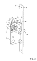
Figure 3 shows the same view asfigure 2 , but with one cover of the lock-housing removed so as to show more details of the inside of the lock-housing. -
Figure 4 shows an exploded top perspective view of the lock-housing showing details of the installation procedure. -
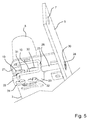
Figure 5 shows the same view asfigure 4 , but in the assembled position. -
Figures 1 - 5 show different views of the same embodiment, therefore the reference numerals used in the figures are all the same. - The lock-
housing 1 shown in the figures is of the kind which will be well understood by the person skilled in the art. In order to simplify the drawings, many of the mechanical details which are not essential for the understanding of the current invention have been removed from the drawings. In general, the lock-housing 1 comprises twocover plates spacer elements 4, a mountingplate 5 and ahook bolt 6. Thehook bolt 6 and thespacer elements 4 are arranged between the two cover plates. The main body of the lock-housing is usually inserted in a recess in one edge of a door (not shown) and fixed to the edge of the door via screws (not shown) inserted through mountingholes 7 in the mountingplate 5. Once the lock-housing 1 is placed in the recess, thelock cylinder 8 is fixed to the lock-housing. This is all standard and should be well known to the person skilled in the art. Therefore, no more details of the typical mounting procedure will be provided herein. It should be noted that the term "lock housing" when used in this application should be understood as some sort of enclosure or frame for a lock mechanism, where the lock mechanism comprises some form of bolt or latch and some form of mechanism for displacing the bolt or latch from an unlocked to a locked position and back again. - It should be noted that all the lock cylinders mentioned in this description are of the Scandinavian oval cylinder type. However, for the sake of simplicity, we will refer to them simply as lock cylinders in the description of this specification. Furthermore, it should be obvious to the person skilled in the art that other types of Rear Mounted Lock Cylinders as defined in this specification can be used instead of Scandinavian Oval Cylinders.
- As can be seen from for example
figure 4 , thelock cylinder 8 is provided with twoholes 9 on its rear face. This is standard for all Scandinavian oval cylinders. The holes are provided with an internal thread. Specially formedscrews 10 are screwed into the holes of the lock cylinder. Thescrews 10 are in this specification also referred to as "fastening elements" since they are used in part to fasten the lock cylinder to the lock-housing as will be described later on. - The
screws 10 have two main portions, afirst portion 11 which is cylindrical and provided with an external thread and asecond portion 12 which is provided with anannular groove 13. Thesecond portion 12 is arranged such that when the first portion is screwed into the lock cylinder, the annular groove is located at a predetermined and well defined distance from the rear face 14 of the lock cylinder. - The lock-housing, as can be seen in for example
figures 3-5 comprises an engagingelement 20 for engaging with the fastening element of the lock cylinder. In this embodiment the engaging element is formed with twoflanges connection portion 23. The twoflanges cover plates flanges protrusions slots cover plates protrusions slots screw 28 which is connected to the engaging element via a threadedhole 29 in theconnection portion 23 of the engagingelement 20. As can be seen fromfigures 1 ,4 and5 , the mountingscrew 28 is accessible from the edge of the door through ahole 30 in the mountingplate 5. As the mountingscrew 28 is rotated, the engaging element will be displaced towards or away from the mounting plate depending on the direction of rotation of the screw. It can also be noted that in this embodiment, the engaging element is arranged within the lock-housing, i.e. between the twocover plates screw 28. However, within the scope of the current invention, embodiments could also be imagined where the engaging element is arranged outside the cover plates or in a lock-housing without cover plates. - The two
flanges element 20 are furthermore each provided with two keyhole cut-outs - The engaging element is designed to have two main positions, an unlocked position and a locked position. In the unlocked position as shown in
figure 4 , the engagingelement 20 is displaced so that the larger hole of the keyhole cut-out is aligned withholes cover plates figure 2 which shows theholes cover plates 2, 3). In the locked position as shown infigure 5 , the engaging element has been displaced such that the large hole of the keyhole cut-out is no longer aligned with the holes in the cover plates. - One procedure for mounting the lock-housing and lock cylinder according to the current invention will now be described with reference to
figures 4 and5 . - The lock-housing is first inserted into a recess of a door and fastened to the door via screws placed through the mounting
holes 7 of the mountingplate 5. The mountingscrew 28 is then adjusted so that the large holes of the keyhole cut-outs are aligned with theholes cover plates elements 10 as described above are then placed in theholes 9 of the lock cylinder. Thelock cylinder 8 is then placed on the lock-housing such that thesecond portions 12 of the fastening elements protrude through theholes cover plates outs screw 28 is then rotated such that the engaging element is displaced towards the mounting plate. As the engaging element displaces, the keyhole cut-outs also displace and the smaller hole portions of the keyhole cut-outs engage with theannular grooves 13 of thefastening elements 10. When the engaging element has been displaced a certain amount, the keyhole cut-outs will have fully engaged theannular grooves 13 of thefastening elements 10 as shown infigure 5 . In this position, the lock cylinder is firmly fastened to the lock-housing. - In one embodiment (not shown) the engaging element could be arranged with a taper between the keyhole cut-out and the fastening element. In this way, as the engaging element is displaced, the taper will pull the fastening element (and thereby the lock cylinder) in towards the lock-housing thereby creating a very tight connection. In another embodiment, the lock-housing is provided with stop elements which clearly mark the locked and unlocked positions of the engaging element.
- As can be understood, no screws which are visible or accessible from the inside of the door are used in this mounting procedure. The only way to remove the lock cylinder from the housing is to unscrew the mounting
screw 28 to displace the engaging element such that the larger hole of the keyhole cut-out again comes into alignment with theholes cover plates screw 28 is only accessible when the door is open. When the door is closed, the mountingscrew 28 is hidden from view and access by the frame of the door. Therefore, when the door is closed and locked, the only way to remove thelock cylinder 8 is to first unlock the door, then open the door and then unscrew the mountingscrew 28. - In the case where two lock cylinders are to be used, one on each side of the door, then a second lock cylinder is provided and fastening elements are placed in holes on the rear face of the second lock cylinder. The engaging element of the lock-housing is then placed in its unlocked position, the two lock cylinders are held in place on the lock-housing, then the mounting screw is adjusted to displace the engaging element where after both lock cylinders are firmly fastened in place on the lock-housing.
- One of the main advantages of this method of fastening a lock cylinder to a lock-housing is that no screws are visible from either the inside or the outside of the door when the door is closed. This prevents the lock cylinders from being removed when the door is closed. This also makes the inside surface of the door more aesthetically pleasing since there are no screws which could distract the attention of a viewer. Furthermore, the same type of cylinder can now be used both for the outside cylinder and the inside cylinder. Previously it was necessary to have both an inside type and an outside type of lock cylinder.
- It should be clear to the person skilled in the art that the embodiment described above could be modified in different ways within the scope of the invention. For example, in the embodiment described above, the fastening elements were provided with an annular groove. However, within the scope of the invention a normal screw could be used instead which is of a predefined length and where the head of the screw would protrude a predetermined distance from the rear face of the lock cylinder. Another example is that instead of using a fastening element with a groove, a fastening element with a hole could be provided. In this case, the engaging element could for example be a pin or screw which is inserted through the hole of the engaging element. Another example is that instead of a mounting screw which adjusts the position of the engaging element, other forms of mounting mechanism could be provided. For example, a lever could be provided which pivots the engaging element around a pivot point. The keyhole cut-outs could in this case also be arranged centred around the pivot point. In an advantageous embodiment, the mounting mechanism could be accessible only from the edge of the door or window, thereby requiring that the door or window were open before being able to adjust the mounting mechanism.
- Furthermore, in the current embodiment, a single engaging element is provided which can engage with two lock cylinders. However, within the scope of the invention, the lock-housing could be provided with two separately displaceable engaging elements which each engage with a different lock cylinder. In general, the person skilled in the art should be able to provide multiple ways in which the current invention could be embodied.
- It should also be noted that in the above description, the lock-housing which has been described has been of the kind which is inserted in a recess in a door or window. However, the current invention can also be used together with furniture type lock-housings. In these types of lock-housings, instead of being mounted in a recess in the door, the lock-housing can be mounted directly to the inside surface of the furniture door or hatch. In these cases, only an outer lock cylinder is used, but the same method for mounting a rear mounted lock cylinder as described above can be used. As with the lock housing which is mounted in a recess, the lock housing of this example can also be completely mounted on the inner side of the door before the lock cylinder is connected to the lock housing.
- Finally it is to be noted that the figures and the above description have shown the example embodiments in a simple and schematic manner. Many of the specific mechanical details have not been shown since the person skilled in the art should be familiar with these details and they would just unnecessarily complicate this description.
Claims (13)
- A method of fastening a Rear Mounted Lock Cylinder (8) to a lock-housing (1) in a door or a window, said method comprising the steps of:a. providing a Rear Mounted Lock Cylinder (8) comprising a threaded hole (9) in its rear surface,b. providing a lock-housing (1) comprising a displaceable engaging element (20),c. providing a fastening element (10),d. inserting and fastening a first portion (11) of the fastening element in the threaded hole (9) in the rear surface of the Rear Mounted Lock Cylinder (8),e. mounting the Rear Mounted Lock Cylinder (8) on the lock-housing (1) such that a second portion (12) of the fastening element (10) is inserted through an opening (33,34) in the lock-housing (1) andf. displacing the displaceable engaging element (20) such that it positively engages the second portion (12) of the fastening element (10) thereby providing a strong connection between the lock-housing (1) and the Rear Mounted Lock Cylinder (8).
- A method according to claim 1, characterized in that the lock-housing (1) is inserted in a recess in the door or window or mounted on a door or window before mounting the lock cylinder(s) (8) on the lock housing.
- A method according to claim 2, characterized in that the lock-housing (1) is inserted in a recess in one edge of the door or window before mounting the lock cylinder(s) (8) on the lock housing.
- A method according to any one of claims 1-3, characterized in that the first portion (11) of the fastening element (10) is provided with an external thread which matches the internal thread of the threaded hole (9) of the Rear Mounted Lock Cylinder (8).
- A method according to any one of claims 1-4, characterized in that the second portion (12) of the fastening element (10) is provided with an annular groove (13).
- A method according to any one of claims 1-5, characterized in that the step of displacing the displaceable engaging element (20) comprises the step of rotating a mounting screw (28) of the lock-housing (1) which is accessible only via an edge of the door or window which would be hidden in the closed position of the door or window but which is accessible when the door or window is open.
- A method according to any one of claims 1-6, characterized in that the Rear Mounted Lock Cylinder (8) is a Scandinavian Oval Cylinder, a Scandinavian Round Cylinder or an equivalent lock cylinder.
- A lock-housing (1) comprising a displaceable engaging element (20) and a mounting mechanism (28), said mounting mechanism (28) being arranged for displacing the displaceable engaging element (20) between two positions, said displaceable engaging element (20) being formed such that in a first position, a portion (12) of a fastening element (10) fastened to a Rear Mounted Lock Cylinder (8) can be inserted into an opening (33,34) in the lock-housing (1) and that in a second position the displaceable engaging element (20) engages the portion (12) of the fastening element (10) inserted into the opening (33,34) in the lock-housing (1) such that the portion (12) of the fastening element (10) inserted into the opening (33,34) in the lock-housing (1) cannot be withdrawn from the opening (33,34) in the lock-housing (1).
- A lock-housing (1) according to claim 8, characterized in that the displaceable engaging element (20) comprises a flange (21, 22) with a keyhole cut-out (31, 32).
- A lock housing (1) according to claim 8 or 9, characterized in that the lock housing is arranged such that when the lock housing is mounted on a door or window, the mounting mechanism (28) is accessible only from the edge of the door or window, thereby requiring that the door or window is open in order to access the mounting mechanism.
- A set comprising a lock-housing (1) and a fastening element (10),a. said lock-housing (1) comprising:i. a displaceable engaging element (20) andii. a mounting mechanism (28) which is arranged to displace the engaging element (20),b. said a fastening element (10) comprising:i. a first portion (11) provided with an external thread which can be fastened to a threaded hole (9) on the rear surface of a Rear Mounted Lock Cylinder (8) andii. a second portion (12) formed complementary to the displaceable engaging element (20) of the lock-housing (1).
- A set according to claim 11, characterized in that the second portion (12) of the fastening element(s) (10) is provided with an annular groove (13).
- A set according to any one of claims 11-12, characterized in that the displaceable engaging element (20) is provided with a keyhole cut-out (21,22) which engages with the second portion (12) of the fastening element (10).
Applications Claiming Priority (1)
| Application Number | Priority Date | Filing Date | Title |
|---|---|---|---|
| DKPA201070354 | 2010-08-11 |
Publications (3)
| Publication Number | Publication Date |
|---|---|
| EP2418341A2 true EP2418341A2 (en) | 2012-02-15 |
| EP2418341A3 EP2418341A3 (en) | 2017-03-08 |
| EP2418341B1 EP2418341B1 (en) | 2018-09-19 |
Family
ID=45121413
Family Applications (1)
| Application Number | Title | Priority Date | Filing Date |
|---|---|---|---|
| EP11177280.2A Active EP2418341B1 (en) | 2010-08-11 | 2011-08-11 | Method of fastening a rear mounted lock cylinder to a lock-housing |
Country Status (2)
| Country | Link |
|---|---|
| EP (1) | EP2418341B1 (en) |
| DK (1) | DK2418341T3 (en) |
Citations (1)
| Publication number | Priority date | Publication date | Assignee | Title |
|---|---|---|---|---|
| US1642047A (en) | 1925-08-01 | 1927-09-13 | Segal Samuel | Casing for locks |
Family Cites Families (5)
| Publication number | Priority date | Publication date | Assignee | Title |
|---|---|---|---|---|
| DE533216C (en) * | 1929-05-22 | 1931-09-18 | Max Schulte | Cylinder lock fastening |
| DE546049C (en) * | 1930-03-15 | 1932-03-12 | Niederdrenk & Co Akt Ges | Attachment for cylinder locks to be attached to a mortise door lock on both sides |
| GB618766A (en) * | 1945-03-30 | 1949-02-28 | Frederick Boyce | Improvements relating to pin tumbler cylinder locks and the like |
| US2696726A (en) * | 1953-03-03 | 1954-12-14 | Segal Samuel | Back plate for locks |
| US2869351A (en) * | 1953-07-09 | 1959-01-20 | Yale & Towne Mfg Co | Lock utilizing interlocking cylinders |
-
2011
- 2011-08-11 EP EP11177280.2A patent/EP2418341B1/en active Active
- 2011-08-11 DK DK11177280.2T patent/DK2418341T3/en active
Patent Citations (1)
| Publication number | Priority date | Publication date | Assignee | Title |
|---|---|---|---|---|
| US1642047A (en) | 1925-08-01 | 1927-09-13 | Segal Samuel | Casing for locks |
Also Published As
| Publication number | Publication date |
|---|---|
| EP2418341A3 (en) | 2017-03-08 |
| EP2418341B1 (en) | 2018-09-19 |
| DK2418341T3 (en) | 2018-12-10 |
Similar Documents
| Publication | Publication Date | Title |
|---|---|---|
| US6223572B1 (en) | Door lock furniture | |
| US9169668B2 (en) | Mortise lock conversion kit for operation with an American cylinder | |
| EP0678644B1 (en) | Removable cylinder locked mullion assembly | |
| FI80118B (en) | INFAESTNINGSANORDNING FOER CYLINDERLAOS. | |
| US6523379B2 (en) | Locking cylinder and housing | |
| US5873272A (en) | Display case lock mechanism with front-assembled core | |
| US5970756A (en) | Dead bolt lock assembly cover | |
| US6941778B2 (en) | Lock | |
| US20020158474A1 (en) | Lock | |
| EP2418341B1 (en) | Method of fastening a rear mounted lock cylinder to a lock-housing | |
| US6601417B2 (en) | Lock | |
| WO2002042588A1 (en) | A locking mechanism | |
| EP2466038B1 (en) | Improvements relating to lock assemblies | |
| EP3330460B1 (en) | A latch assembly | |
| JP2006097360A (en) | Cylinder and lock case mounting mechanism of double-sided cylinder inter-grip rim lock | |
| EP1183433B1 (en) | Lock | |
| GB2440743A (en) | Lock with spacing member located between closure and either flange or securing device of lock | |
| AU2024203506B2 (en) | A lock assembly | |
| US20050223764A1 (en) | Retaining mechanism for mortise cylinders | |
| AU2007254650A1 (en) | Strengthened cylinder lock assembly | |
| AU2019100081A4 (en) | Lock appliance without needing to adjust installation position | |
| EP3241963B1 (en) | Lock with multiple mounting plates | |
| NZ760173A (en) | An escutcheon for a door, a door furniture kit, and a method for mounting an escutcheon to a door | |
| US1192963A (en) | Lock. | |
| GB2288628A (en) | Lock assembly |
Legal Events
| Date | Code | Title | Description |
|---|---|---|---|
| AK | Designated contracting states |
Kind code of ref document: A2 Designated state(s): AL AT BE BG CH CY CZ DE DK EE ES FI FR GB GR HR HU IE IS IT LI LT LU LV MC MK MT NL NO PL PT RO RS SE SI SK SM TR |
|
| AX | Request for extension of the european patent |
Extension state: BA ME |
|
| PUAI | Public reference made under article 153(3) epc to a published international application that has entered the european phase |
Free format text: ORIGINAL CODE: 0009012 |
|
| PUAL | Search report despatched |
Free format text: ORIGINAL CODE: 0009013 |
|
| AK | Designated contracting states |
Kind code of ref document: A3 Designated state(s): AL AT BE BG CH CY CZ DE DK EE ES FI FR GB GR HR HU IE IS IT LI LT LU LV MC MK MT NL NO PL PT RO RS SE SI SK SM TR |
|
| AX | Request for extension of the european patent |
Extension state: BA ME |
|
| RIC1 | Information provided on ipc code assigned before grant |
Ipc: E05B 9/08 20060101AFI20170130BHEP |
|
| STAA | Information on the status of an ep patent application or granted ep patent |
Free format text: STATUS: REQUEST FOR EXAMINATION WAS MADE |
|
| 17P | Request for examination filed |
Effective date: 20170908 |
|
| RBV | Designated contracting states (corrected) |
Designated state(s): AL AT BE BG CH CY CZ DE DK EE ES FI FR GB GR HR HU IE IS IT LI LT LU LV MC MK MT NL NO PL PT RO RS SE SI SK SM TR |
|
| GRAP | Despatch of communication of intention to grant a patent |
Free format text: ORIGINAL CODE: EPIDOSNIGR1 |
|
| STAA | Information on the status of an ep patent application or granted ep patent |
Free format text: STATUS: GRANT OF PATENT IS INTENDED |
|
| INTG | Intention to grant announced |
Effective date: 20180221 |
|
| GRAS | Grant fee paid |
Free format text: ORIGINAL CODE: EPIDOSNIGR3 |
|
| GRAA | (expected) grant |
Free format text: ORIGINAL CODE: 0009210 |
|
| STAA | Information on the status of an ep patent application or granted ep patent |
Free format text: STATUS: THE PATENT HAS BEEN GRANTED |
|
| AK | Designated contracting states |
Kind code of ref document: B1 Designated state(s): AL AT BE BG CH CY CZ DE DK EE ES FI FR GB GR HR HU IE IS IT LI LT LU LV MC MK MT NL NO PL PT RO RS SE SI SK SM TR |
|
| REG | Reference to a national code |
Ref country code: GB Ref legal event code: FG4D |
|
| REG | Reference to a national code |
Ref country code: CH Ref legal event code: EP |
|
| REG | Reference to a national code |
Ref country code: AT Ref legal event code: REF Ref document number: 1043442 Country of ref document: AT Kind code of ref document: T Effective date: 20181015 |
|
| REG | Reference to a national code |
Ref country code: IE Ref legal event code: FG4D |
|
| REG | Reference to a national code |
Ref country code: DE Ref legal event code: R096 Ref document number: 602011052130 Country of ref document: DE |
|
| REG | Reference to a national code |
Ref country code: DK Ref legal event code: T3 Effective date: 20181203 |
|
| REG | Reference to a national code |
Ref country code: SE Ref legal event code: TRGR |
|
| REG | Reference to a national code |
Ref country code: NL Ref legal event code: MP Effective date: 20180919 |
|
| PG25 | Lapsed in a contracting state [announced via postgrant information from national office to epo] |
Ref country code: RS Free format text: LAPSE BECAUSE OF FAILURE TO SUBMIT A TRANSLATION OF THE DESCRIPTION OR TO PAY THE FEE WITHIN THE PRESCRIBED TIME-LIMIT Effective date: 20180919 Ref country code: LT Free format text: LAPSE BECAUSE OF FAILURE TO SUBMIT A TRANSLATION OF THE DESCRIPTION OR TO PAY THE FEE WITHIN THE PRESCRIBED TIME-LIMIT Effective date: 20180919 Ref country code: BG Free format text: LAPSE BECAUSE OF FAILURE TO SUBMIT A TRANSLATION OF THE DESCRIPTION OR TO PAY THE FEE WITHIN THE PRESCRIBED TIME-LIMIT Effective date: 20181219 Ref country code: FI Free format text: LAPSE BECAUSE OF FAILURE TO SUBMIT A TRANSLATION OF THE DESCRIPTION OR TO PAY THE FEE WITHIN THE PRESCRIBED TIME-LIMIT Effective date: 20180919 Ref country code: NO Free format text: LAPSE BECAUSE OF FAILURE TO SUBMIT A TRANSLATION OF THE DESCRIPTION OR TO PAY THE FEE WITHIN THE PRESCRIBED TIME-LIMIT Effective date: 20181219 Ref country code: GR Free format text: LAPSE BECAUSE OF FAILURE TO SUBMIT A TRANSLATION OF THE DESCRIPTION OR TO PAY THE FEE WITHIN THE PRESCRIBED TIME-LIMIT Effective date: 20181220 |
|
| REG | Reference to a national code |
Ref country code: LT Ref legal event code: MG4D |
|
| PG25 | Lapsed in a contracting state [announced via postgrant information from national office to epo] |
Ref country code: LV Free format text: LAPSE BECAUSE OF FAILURE TO SUBMIT A TRANSLATION OF THE DESCRIPTION OR TO PAY THE FEE WITHIN THE PRESCRIBED TIME-LIMIT Effective date: 20180919 Ref country code: HR Free format text: LAPSE BECAUSE OF FAILURE TO SUBMIT A TRANSLATION OF THE DESCRIPTION OR TO PAY THE FEE WITHIN THE PRESCRIBED TIME-LIMIT Effective date: 20180919 Ref country code: AL Free format text: LAPSE BECAUSE OF FAILURE TO SUBMIT A TRANSLATION OF THE DESCRIPTION OR TO PAY THE FEE WITHIN THE PRESCRIBED TIME-LIMIT Effective date: 20180919 |
|
| REG | Reference to a national code |
Ref country code: AT Ref legal event code: MK05 Ref document number: 1043442 Country of ref document: AT Kind code of ref document: T Effective date: 20180919 |
|
| PG25 | Lapsed in a contracting state [announced via postgrant information from national office to epo] |
Ref country code: RO Free format text: LAPSE BECAUSE OF FAILURE TO SUBMIT A TRANSLATION OF THE DESCRIPTION OR TO PAY THE FEE WITHIN THE PRESCRIBED TIME-LIMIT Effective date: 20180919 Ref country code: CZ Free format text: LAPSE BECAUSE OF FAILURE TO SUBMIT A TRANSLATION OF THE DESCRIPTION OR TO PAY THE FEE WITHIN THE PRESCRIBED TIME-LIMIT Effective date: 20180919 Ref country code: PL Free format text: LAPSE BECAUSE OF FAILURE TO SUBMIT A TRANSLATION OF THE DESCRIPTION OR TO PAY THE FEE WITHIN THE PRESCRIBED TIME-LIMIT Effective date: 20180919 Ref country code: IS Free format text: LAPSE BECAUSE OF FAILURE TO SUBMIT A TRANSLATION OF THE DESCRIPTION OR TO PAY THE FEE WITHIN THE PRESCRIBED TIME-LIMIT Effective date: 20190119 Ref country code: ES Free format text: LAPSE BECAUSE OF FAILURE TO SUBMIT A TRANSLATION OF THE DESCRIPTION OR TO PAY THE FEE WITHIN THE PRESCRIBED TIME-LIMIT Effective date: 20180919 Ref country code: NL Free format text: LAPSE BECAUSE OF FAILURE TO SUBMIT A TRANSLATION OF THE DESCRIPTION OR TO PAY THE FEE WITHIN THE PRESCRIBED TIME-LIMIT Effective date: 20180919 Ref country code: AT Free format text: LAPSE BECAUSE OF FAILURE TO SUBMIT A TRANSLATION OF THE DESCRIPTION OR TO PAY THE FEE WITHIN THE PRESCRIBED TIME-LIMIT Effective date: 20180919 Ref country code: IT Free format text: LAPSE BECAUSE OF FAILURE TO SUBMIT A TRANSLATION OF THE DESCRIPTION OR TO PAY THE FEE WITHIN THE PRESCRIBED TIME-LIMIT Effective date: 20180919 Ref country code: EE Free format text: LAPSE BECAUSE OF FAILURE TO SUBMIT A TRANSLATION OF THE DESCRIPTION OR TO PAY THE FEE WITHIN THE PRESCRIBED TIME-LIMIT Effective date: 20180919 |
|
| PG25 | Lapsed in a contracting state [announced via postgrant information from national office to epo] |
Ref country code: SM Free format text: LAPSE BECAUSE OF FAILURE TO SUBMIT A TRANSLATION OF THE DESCRIPTION OR TO PAY THE FEE WITHIN THE PRESCRIBED TIME-LIMIT Effective date: 20180919 Ref country code: SK Free format text: LAPSE BECAUSE OF FAILURE TO SUBMIT A TRANSLATION OF THE DESCRIPTION OR TO PAY THE FEE WITHIN THE PRESCRIBED TIME-LIMIT Effective date: 20180919 Ref country code: PT Free format text: LAPSE BECAUSE OF FAILURE TO SUBMIT A TRANSLATION OF THE DESCRIPTION OR TO PAY THE FEE WITHIN THE PRESCRIBED TIME-LIMIT Effective date: 20190119 |
|
| REG | Reference to a national code |
Ref country code: DE Ref legal event code: R097 Ref document number: 602011052130 Country of ref document: DE |
|
| PLBE | No opposition filed within time limit |
Free format text: ORIGINAL CODE: 0009261 |
|
| STAA | Information on the status of an ep patent application or granted ep patent |
Free format text: STATUS: NO OPPOSITION FILED WITHIN TIME LIMIT |
|
| 26N | No opposition filed |
Effective date: 20190620 |
|
| PG25 | Lapsed in a contracting state [announced via postgrant information from national office to epo] |
Ref country code: SI Free format text: LAPSE BECAUSE OF FAILURE TO SUBMIT A TRANSLATION OF THE DESCRIPTION OR TO PAY THE FEE WITHIN THE PRESCRIBED TIME-LIMIT Effective date: 20180919 |
|
| PGFP | Annual fee paid to national office [announced via postgrant information from national office to epo] |
Ref country code: SE Payment date: 20190813 Year of fee payment: 9 |
|
| REG | Reference to a national code |
Ref country code: DE Ref legal event code: R119 Ref document number: 602011052130 Country of ref document: DE |
|
| PG25 | Lapsed in a contracting state [announced via postgrant information from national office to epo] |
Ref country code: TR Free format text: LAPSE BECAUSE OF FAILURE TO SUBMIT A TRANSLATION OF THE DESCRIPTION OR TO PAY THE FEE WITHIN THE PRESCRIBED TIME-LIMIT Effective date: 20180919 |
|
| PG25 | Lapsed in a contracting state [announced via postgrant information from national office to epo] |
Ref country code: CH Free format text: LAPSE BECAUSE OF NON-PAYMENT OF DUE FEES Effective date: 20190831 Ref country code: MC Free format text: LAPSE BECAUSE OF FAILURE TO SUBMIT A TRANSLATION OF THE DESCRIPTION OR TO PAY THE FEE WITHIN THE PRESCRIBED TIME-LIMIT Effective date: 20180919 Ref country code: LU Free format text: LAPSE BECAUSE OF NON-PAYMENT OF DUE FEES Effective date: 20190811 Ref country code: LI Free format text: LAPSE BECAUSE OF NON-PAYMENT OF DUE FEES Effective date: 20190831 |
|
| REG | Reference to a national code |
Ref country code: BE Ref legal event code: MM Effective date: 20190831 |
|
| PG25 | Lapsed in a contracting state [announced via postgrant information from national office to epo] |
Ref country code: DE Free format text: LAPSE BECAUSE OF NON-PAYMENT OF DUE FEES Effective date: 20200303 Ref country code: IE Free format text: LAPSE BECAUSE OF NON-PAYMENT OF DUE FEES Effective date: 20190811 Ref country code: FR Free format text: LAPSE BECAUSE OF NON-PAYMENT OF DUE FEES Effective date: 20190831 |
|
| PG25 | Lapsed in a contracting state [announced via postgrant information from national office to epo] |
Ref country code: BE Free format text: LAPSE BECAUSE OF NON-PAYMENT OF DUE FEES Effective date: 20190831 |
|
| PGFP | Annual fee paid to national office [announced via postgrant information from national office to epo] |
Ref country code: GB Payment date: 20200729 Year of fee payment: 10 |
|
| REG | Reference to a national code |
Ref country code: SE Ref legal event code: EUG |
|
| PG25 | Lapsed in a contracting state [announced via postgrant information from national office to epo] |
Ref country code: CY Free format text: LAPSE BECAUSE OF FAILURE TO SUBMIT A TRANSLATION OF THE DESCRIPTION OR TO PAY THE FEE WITHIN THE PRESCRIBED TIME-LIMIT Effective date: 20180919 Ref country code: SE Free format text: LAPSE BECAUSE OF NON-PAYMENT OF DUE FEES Effective date: 20200812 |
|
| PG25 | Lapsed in a contracting state [announced via postgrant information from national office to epo] |
Ref country code: MT Free format text: LAPSE BECAUSE OF FAILURE TO SUBMIT A TRANSLATION OF THE DESCRIPTION OR TO PAY THE FEE WITHIN THE PRESCRIBED TIME-LIMIT Effective date: 20180919 Ref country code: HU Free format text: LAPSE BECAUSE OF FAILURE TO SUBMIT A TRANSLATION OF THE DESCRIPTION OR TO PAY THE FEE WITHIN THE PRESCRIBED TIME-LIMIT; INVALID AB INITIO Effective date: 20110811 |
|
| GBPC | Gb: european patent ceased through non-payment of renewal fee |
Effective date: 20210811 |
|
| PG25 | Lapsed in a contracting state [announced via postgrant information from national office to epo] |
Ref country code: MK Free format text: LAPSE BECAUSE OF FAILURE TO SUBMIT A TRANSLATION OF THE DESCRIPTION OR TO PAY THE FEE WITHIN THE PRESCRIBED TIME-LIMIT Effective date: 20180919 |
|
| PG25 | Lapsed in a contracting state [announced via postgrant information from national office to epo] |
Ref country code: GB Free format text: LAPSE BECAUSE OF NON-PAYMENT OF DUE FEES Effective date: 20210811 |
|
| PGFP | Annual fee paid to national office [announced via postgrant information from national office to epo] |
Ref country code: DK Payment date: 20250814 Year of fee payment: 15 |