EP2418322B1 - Drainage gutter - Google Patents
Drainage gutter Download PDFInfo
- Publication number
- EP2418322B1 EP2418322B1 EP10013406.3A EP10013406A EP2418322B1 EP 2418322 B1 EP2418322 B1 EP 2418322B1 EP 10013406 A EP10013406 A EP 10013406A EP 2418322 B1 EP2418322 B1 EP 2418322B1
- Authority
- EP
- European Patent Office
- Prior art keywords
- tube
- face wall
- tunnel
- rail
- drainage channel
- Prior art date
- Legal status (The legal status is an assumption and is not a legal conclusion. Google has not performed a legal analysis and makes no representation as to the accuracy of the status listed.)
- Not-in-force
Links
Images


Classifications
-
- E—FIXED CONSTRUCTIONS
- E01—CONSTRUCTION OF ROADS, RAILWAYS, OR BRIDGES
- E01B—PERMANENT WAY; PERMANENT-WAY TOOLS; MACHINES FOR MAKING RAILWAYS OF ALL KINDS
- E01B21/00—Track superstructure adapted for tramways in paved streets
- E01B21/02—Special supporting means; Draining of rails
Definitions
- the present invention relates to a drainage channel for drainage of rails, in particular tram rails, comprising a channel body with an end wall, which is associated with an inlet opening for draining a arranged in the rail head of the rail rail groove via an inlet funnel, wherein the inlet funnel is associated with a front panel, which, forming part of the end wall, inserted into a receptacle associated with the end wall in the horizontal direction, can be.
- Such a drainage channel is already out of the DE 20 2006 008 831 U1 previously known.
- assign the inlet funnel of the end wall forming plate characterized in that the inlet funnel is inserted through an inlet opening and locked in a stop position.
- the rail groove drainage openings which are provided at certain intervals.
- the rails are crossed by drainage channels, into which the drainage openings of the rails open.
- the abovementioned, previously known solution provides for a beak-shaped inlet funnel, which is pushed from inside to the underside of the rail by means of a rail to the end wall of the drainage channel and fastened there.
- either a drain pipe opening into the sewage system can be provided, or else the gutter line can be continued.
- the water guided by the drainage channel can pass under the rail.
- a tunnel tube is provided, which connect the drainage channels or the drainage channel and the drainage pipe to each other below the rail from both sides.
- the present invention is intended to show an alternative to push-through drainage tubes.
- the inlet through the drainage opening of the rail into the gutter body usually takes place via an inlet opening of the end wall, which is assigned an inlet funnel.
- the solution according to the invention in the region of the end wall on a front panel, to which an inlet funnel is attached.
- a front panel is inserted into a receptacle of the end wall, which passes transversely through the end wall in the direction parallel to the rail.
- the inlet funnel is therefore to be fastened to the front wall from outside the inside of the channel.
- this is a rectangular receptacle, so that the front panel can be inserted from both sides into the receptacle. Therefore, not the end wall as such has the inlet opening, but rather the front panel, through which the water flowing in via the drainage opening of the rail passes through the inlet funnel into the channel.
- the inlet opening is provided in the end wall.
- the invention provides in this case that the inlet funnel is made in two parts, with two funnel halves are pushed towards each other in the direction parallel to the rails and meet in a central stop position where they unite to form a common inlet funnel.
- the inlet funnel engages under the drainage opening of the rail and connects it to the end wall in such a way that the water to be drained from the drainage opening into the inlet funnel can enter the gutter body through the end wall and its inlet opening.
- the inlet funnel is in this case preferably formed of two different materials, namely substantially of a rigid, dimensionally stable material and in the region of the rail under cross-leading edge of a soft, adapting to the position of the rail material.
- the two funnel halves are each provided with one, preferably two or more, guide elements which are each accommodated in a rail guide flanking the inlet opening on one or both sides.
- a rail guide allows the exact positioning of the inlet funnel in front of the inlet opening of the end wall, so that the two halves of the inlet funnel connect in their stop positions to the common inlet funnel.
- a sealing lip is arranged in an advantageous embodiment, so that water entering via the inlet funnel does not seep down at the abutting edge of the two funnel halves.
- the rail guides in the region of their stop position on a latch, in which engage the guide elements of the hopper halves, as soon as they are moved to the stop position.
- a further development of the aforementioned drainage channel has in the region of a tunnel opening provided in its end wall a projection on which a tunnel tube can be slid from the outside. Such, pushed out from the outside tunnel tube has the advantage that a subsequent displacement of the tunnel tube, by whatever circumstances, is excluded.
- the tunnel tube can be easily positioned from the outside and continue in the other the installation either as a drain pipe or as an extended drainage channel.
- the tunnel tube in two parts, ideally two identical parts are used.
- the two, preferably identical, tube halves are connected together along their longitudinal edges, wherein locking means and corresponding counter-locking means are provided in particular along these longitudinal edges.
- the locking means engage in the counter-locking means in such a way that, at least when placed on the projection of the end wall, a secure mounting of the thus assembled tunnel tube is ensured.
- the tube halves may, in a concrete embodiment along a longitudinal edge having a tab which engages over a portion of the respective opposite longitudinal edge of the respective other tube half.
- locking means and counter-locking means can then be arranged.
- a locking means or counter-locking means are particularly preferably a bead and a hierein engaging bulge to provide, which at least largely positively and / or non-positively engage with each other.
- any other locking means and counter-locking means are also used.
- a tube half can be slipped from one side onto the projection, after which the other tube half is pushed over the projection from the other side. In the successive meeting of the two tube halves then snap the locking means in the counter-locking means and connect the tube halves to a common tunnel tube.
- a drain pipe is provided on the opposite side of the channel, so opposite the considered drainage channel, so this also has an end wall with a projection which protrudes away from the drain pipe, ie under the rail.
- this projection encloses on the outside, or engages the tunnel tube in said projection.
- a stop for the tunnel tube may be provided within the projection, so that it is held in place.
- a second drainage channel may be arranged on the other side of the rail, which is constructed substantially identical to the first.
- the second drainage channel can also, like the end wall of the drainage tube, have a projection which engages around the tunnel tube on the outside, instead of interfering therewith.
- a facing or a non-penetrated end wall must be provided, since, as already explained above, a drainage opening of the rail is only present on one side.
- an inlet into this second drainage channel at best by the tunnel tube, but not done by an inlet funnel or an inlet opening in the front wall.
- the channel element can either be connected directly to an end wall, ie the end wall can be made in one piece with the channel element.
- the end wall can be put directly on the gutter body, in particular to connect this with the end wall, for example with the interposition of a seal.
- the end wall is associated with a short, separate channel section, which can be connected as an end piece in the usual way with the drainage channel.
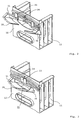
- FIG. 1 shows a drainage channel in an exploded view.
- the drainage channel consists of a channel body 10 which is closed on both sides by end elements 11.
- the end elements 11 are configured such that they are designed to drain a railroad track then to drain.
- the end elements 11 inlet openings 15 through which collected in the tram rail surface water can enter the drainage channel.
- To undercut the rails additionally has the end member 11 a tunnel opening 13, which is surrounded by a projection 14. In this way, introduced into the drainage channel surface water can be introduced from the channel body 10 out into the sewage system or on the other side of the tram track continued drainage channels are derived.
- FIG. 2 shows as a detail of such a drainage channel a front element 11, which has an inlet funnel 30 for introducing the surface water originating from the rail 40 into the channel body 10.
- This inlet funnel is formed in two parts in the embodiment shown, namely from a first funnel half 31 and a second funnel half 32, which are moved towards each other from both sides of an inlet opening via a rail guide 34.
- the first funnel half 31 and the second funnel half 32 each have guide elements 33 which engage in the rail guide 34.
- FIG. 3 shows the two funnel halves 31, 32 in their stop position.
- the first funnel half 31 and the second funnel half 32 complement each other to form a common inlet funnel 30, wherein a sealing element 35 in the form of a sealing lip is arranged along the abutting edge.
- a locking is also provided, which prevents a disengagement of the funnel halves 31 and 32.
- FIG. 4 shows an alternative embodiment of the inlet funnel 30, which is connected in this case with a front panel 36. Together with the front panel 36 of this feed hopper 30 is inserted into a receptacle 16 of the end wall 12.
- the receptacle 16 in this case represents the end wall 12 transversely by cross-rectangle, which can be completely filled by the front panel 36.
- a guide rail is provided, in which the front panel 36, preferably sealing, can engage.
- FIG. 5 shows the front panel 36 in its fully inserted position.
- a lateral insertion is possible parallel to the course of the adjacent rail 40, while the feed hopper 30 in this case remains permanently in contact with the rail head 41 in the region of the rail groove 42.
- the inlet funnel 30 engages under the drainage opening 43 within the rail groove 42, so that the surface water standing in the rail groove can enter via the drainage opening 43 and the inlet opening 15 into the drainage channel.
- the inlet funnel consists of a two-part material, namely in the region of the funnel of a stiff, solid material and in the region of its leading edge, which comes into contact with the rail head 41, from a soft, adaptable in its shape material.
- the rail 40 is underrun by a tunnel tube 20, which is connected in the region of the projection 14 with the end wall 12 of the drainage channel.
- FIG. 6 shows such a tunnel tube 20, which is composed of a first tube half 21 and a second tube half 22.
- a tunnel tube 20 which is composed of a first tube half 21 and a second tube half 22.
- each of the two tube halves 21, 22 along a longitudinal edge 23 has a bead 25 into which a flap 24 associated bulge 26 can engage.
- both tube halves 21, 22 form a tunnel tube 20, which configuration is inherently unstable. By a simple lifting transverse to the longitudinal axis this can be separated again.
- FIG. 8 This is prevented as in FIG. 8 is shown.
- the composite tunnel tube 20 is pushed onto the projection 14 of the end wall 12, which thereby prevents an upward or longitudinal deflection. This results in the tunnel tube 20 in its installed state, a stable construction, which has no disadvantages over a one-piece tunnel tube 20.
- FIG. 8 is from the drainage channel opposite side an end wall 18 of a drain pipe used for the other side boundary of the tunnel tube 20, so that the drainage channel can derive the guided in her water, which enters from the rail groove 42 via the drainage opening 43 into the gutter body 10, directly into the sewer.
- FIG. 9 An appropriate compilation is in FIG. 9 shown, it can be seen through the lateral plan view that the end wall 18 of the drain pipe has a projection 19 which does not engage in the tunnel tube 20, but rather this engages on the outside. A removal of the tunnel tube 20 without a prior removal of the end wall 18 of the drain pipe is thus prevented.
- FIG. 3 shows a configuration according to which a continuation of the drainage channel beyond the rail 40 is possible.
- the drainage channels are laid on both sides of the rails 40, such that the end elements 11 have mutually opposite projections 14.
- the tunnel tube 20 is then composed from both sides of the two tube halves 21, 22 by first the first tube half 21 is pushed over the projection 14 and then from the other side, the second tube half 22 is pushed over it.
- the bulge present in the respective lug lying over the longitudinal edge locks with the bead running along the longitudinal edge, so that after positioning the tube halves 21, 22 a separation is only possible against bending of the latches.
Description
Die vorliegende Erfindung betrifft eine Entwässerungsrinne zur Entwässerung von Schienen, insbesondere von Straßenbahnschienen, umfassend einen Rinnenkörper mit einer Stirnwand, welcher eine Einlauföffnung zur Entwässerung einer im Schienenkopf der Schiene angeordneten Schienenrille über einen Einlauftrichter zugeordnet ist, wobei der Einlauftrichter einer Stirnblende zugeordnet ist, welche, einen Teil der Stirnwand bildend, in eine der Stirnwand zugeordneten Aufnahme in horizontaler Richtung eingeschoben, werden kann.The present invention relates to a drainage channel for drainage of rails, in particular tram rails, comprising a channel body with an end wall, which is associated with an inlet opening for draining a arranged in the rail head of the rail rail groove via an inlet funnel, wherein the inlet funnel is associated with a front panel, which, forming part of the end wall, inserted into a receptacle associated with the end wall in the horizontal direction, can be.
Eine derartige Entwässerungsrinne ist bereits aus der
Ferner ist eine ähnliche Entwässerungsrinne aus der französischen Patentanmeldung
Dies erfolgt über in der Schienenrille vorgesehene Entwässerungsöffnungen, welche in gewissen Abständen vorgesehen sind. Im Bereich dieser Entwässerungsöffnungen der Schienenrillen werden die Schienen von Entwässerungsrinnen gekreuzt, in welche die Entwässerungsöffnungen der Schienen hineinmünden. Hierzu sieht die oben genannte, vorbekannte Lösung einen schnabelförmigen Einlauftrichter vor, welcher durch eine an die schienenstoßende Stirnwand der Entwässerungsrinne von inwendig her an die Unterseite der Schiene angeschoben und dort befestigt wird.This is done via provided in the rail groove drainage openings, which are provided at certain intervals. In the area of these drainage openings of the rail grooves, the rails are crossed by drainage channels, into which the drainage openings of the rails open. For this purpose, the abovementioned, previously known solution provides for a beak-shaped inlet funnel, which is pushed from inside to the underside of the rail by means of a rail to the end wall of the drainage channel and fastened there.
Um jenseits der Schiene die Entwässerung fortzuführen, kann dort entweder ein in die Kanalisation mündendes Abflussrohr vorgesehen sein, oder aber der Rinnenstrang weitergeführt werden. In beiden Fällen ist es erforderlich, dass das von der Entwässerungsrinne geführte Wasser unter der Schiene hindurch passieren kann. Hierfür ist wiederum eine Tunnelröhre vorgesehen, welche unterhalb der Schiene von beiden Seiten her die an die Schiene stoßenden Entwässerungsrinnen bzw. die Entwässerungsrinne und das Abflussrohr miteinander verbinden. Auch hier ist gemäß der oben stehenden französischen Schrift vorgesehen, zunächst die Rinnen beiderseits zu verlegen und dann, in einem abschließenden Schritt, unter der Schiene hindurch von der Innenseite der Entwässerungsrinne her das Tunnelrohr durch die hierfür vorgesehenen Öffnungen in den Stirnwänden der Entwässerungsrinnen durchzuschieben.In order to continue the drainage on the other side of the rail, either a drain pipe opening into the sewage system can be provided, or else the gutter line can be continued. In both cases, it is necessary that the water guided by the drainage channel can pass under the rail. For this purpose, in turn, a tunnel tube is provided, which connect the drainage channels or the drainage channel and the drainage pipe to each other below the rail from both sides. Again, according to the above French document, it is provided first to lay the gutters on both sides and then, in a final step, under the rail, from the inside of the drainage channel, the tunnel tube through the space provided for this purpose Push through openings in the end walls of the drainage channels.
Die vorliegende Erfindung soll eine Alternative zu durchschiebbaren Entwässerungsröhren aufzeigen.The present invention is intended to show an alternative to push-through drainage tubes.
Dies gelingt durch eine Entwässerungsrinne mit den Merkmalen des Anspruchs 1. Weitere, sinnvolle Ausgestaltungen dieser Entwässerungsrinne können den Unteransprüchen entnommen werden.This is achieved by a drainage channel with the features of
Erfindungsgemäß ist es vorgesehen, im wesentlichen ebenfalls eine oder mehrere Entwässerungsrinnen in einer die Schiene kreuzenden Richtung zu verlegen. Wie bereits erwähnt, erfolgt der Einlauf durch die Entwässerungsöffnung der Schiene in den Rinnenkörper hinein üblicherweise über eine Einlauföffnung der Stirnwand, welcher ein Einlauftrichter zugeordnet ist. Im Unterschied zum Stand der Technik weist jedoch die erfindungsgemäße Lösung im Bereich der Stirnwand eine Stirnblende auf, an welcher ein Einlauftrichter befestigt ist. Eine derartige Stirnblende wird in eine Aufnahme der Stirnwand eingeschoben, welche die Stirnwand in Parallelrichtung zur Schiene quer durchgreift. Der Einlauftrichter ist also von außerhalb des Rinneninneren her an der Stirnwand zu befestigen. Vorzugsweise ist vorgesehen, dass es sich hierbei um eine rechteckige Aufnahme handelt, so dass die Stirnblende von beiden Seiten her in die Aufnahme eingeschoben werden kann. Nicht die Stirnwand als solche weist daher die Einlauföffnung auf, sondern vielmehr die Stirnblende, durch welche das über die Entwässerungsöffnung der Schiene einströmende Wasser über den Einlauftrichter in die Rinne gelangt.According to the invention, it is also provided to essentially lay one or more drainage channels in a direction crossing the rail. As already mentioned, the inlet through the drainage opening of the rail into the gutter body usually takes place via an inlet opening of the end wall, which is assigned an inlet funnel. In contrast to the prior art, however, the solution according to the invention in the region of the end wall on a front panel, to which an inlet funnel is attached. Such a front panel is inserted into a receptacle of the end wall, which passes transversely through the end wall in the direction parallel to the rail. The inlet funnel is therefore to be fastened to the front wall from outside the inside of the channel. It is preferably provided that this is a rectangular receptacle, so that the front panel can be inserted from both sides into the receptacle. Therefore, not the end wall as such has the inlet opening, but rather the front panel, through which the water flowing in via the drainage opening of the rail passes through the inlet funnel into the channel.
Eine Alternative hierzu sieht vor, dass die Einlauföffnung in der Stirnwand vorgesehen ist. Für die Befestigung des Einlauftrichters sieht die Erfindung in diesem Fall vor, dass der Einlauftrichter zweiteilig ausgeführt ist, wobei zwei Trichterhälften jeweils in Parallelrichtung zu den Schienen aufeinander zu geschoben werden und in einer mittleren Anschlagsposition aufeinander treffen, wo sie sich zu einem gemeinsamen Einlauftrichter vereinen. Der Einlauftrichter untergreift hierbei die Entwässerungsöffnung der Schiene und verbindet diese mit der Stirnwand, derart, dass das aus der Entwässerungsöffnung in den Einlauftrichter einlaufende, abzuführende Wasser durch die Stirnwand und deren Einlauföffnung in den Rinnenkörper eintreten kann. Der Einlauftrichter ist hierbei vorzugsweise aus zwei unterschiedlichen Materialien gebildet, nämlich im wesentlichen aus einem steifen, formstabilen Material und im Bereich der die Schiene untergreifenden Vorderkante aus einem weichen, sich an die Lage der Schiene anpassenden Material.An alternative to this provides that the inlet opening is provided in the end wall. For the attachment of the inlet funnel, the invention provides in this case that the inlet funnel is made in two parts, with two funnel halves are pushed towards each other in the direction parallel to the rails and meet in a central stop position where they unite to form a common inlet funnel. In this case, the inlet funnel engages under the drainage opening of the rail and connects it to the end wall in such a way that the water to be drained from the drainage opening into the inlet funnel can enter the gutter body through the end wall and its inlet opening. The inlet funnel is in this case preferably formed of two different materials, namely substantially of a rigid, dimensionally stable material and in the region of the rail under cross-leading edge of a soft, adapting to the position of the rail material.
In konkreter Ausgestaltung sind die beiden Trichterhälften jeweils mit einem, vorzugsweise zwei oder mehreren, Führungselementen versehen, welche jeweils in einer die Einlauföffnung einseitig oder beidseitig flankierenden Schienenführung aufgenommen sind. Eine derartige Schienenführung erlaubt die exakte Positionierung des Einlauftrichters vor der Einlauföffnung der Stirnwand, so, dass die beiden Hälften des Einlauftrichters sich in ihren Anschlagspositionen zu dem gemeinsamen Einlauftrichter verbinden. Zwischen den beiden Trichterhälften ist hierbei in vorteilhafter Ausgestaltung eine Dichtlippe angeordnet, so dass über den Einlauftrichter einlaufendes Wasser nicht an der Stoßkante der beiden Trichterhälften nach unten versickert.In a concrete embodiment, the two funnel halves are each provided with one, preferably two or more, guide elements which are each accommodated in a rail guide flanking the inlet opening on one or both sides. Such a rail guide allows the exact positioning of the inlet funnel in front of the inlet opening of the end wall, so that the two halves of the inlet funnel connect in their stop positions to the common inlet funnel. Between the two funnel halves, a sealing lip is arranged in an advantageous embodiment, so that water entering via the inlet funnel does not seep down at the abutting edge of the two funnel halves.
In besonders bevorzugter Ausgestaltung weisen die Schienenführungen im Bereich ihrer Anschlagsposition eine Verrastung auf, in welche die Führungselemente der Trichterhälften eingreifen, sobald diese in die Anschlagsposition verbracht werden. Hierdurch ist ein Ausweichen der Trichterhälften ein- oder beidseitig vermieden, so dass nach einer einmaligen Montage der Einlauftrichter in seiner Position verbleibt.In a particularly preferred embodiment, the rail guides in the region of their stop position on a latch, in which engage the guide elements of the hopper halves, as soon as they are moved to the stop position. As a result, a deflection of the funnel halves is avoided on one or both sides, so that after a single installation of the inlet funnel remains in its position.
Eine Weiterbildung der vorgenannten Entwässerungsrinne weist im Bereich einer in ihrer Stirnwand vorgesehenen Tunnelöffnung eine Auskragung auf, auf welche von der Außenseite her eine Tunnelröhre aufgeschoben werden kann. Eine derartige, von außen her aufgeschobene Tunnelröhre hat den Vorteil, dass ein nachträgliches Verschieben der Tunnelröhre, durch welche Umstände auch immer, ausgeschlossen ist. Durch die genannte Auskragung auf der Stirnwand der Entwässerungsrinne lässt sich die Tunnelröhre ohne weiteres von außen her positionieren und im weiteren die Verlegung entweder als Abflussrohr oder als verlängerte Entwässerungsrinne fortsetzen.A further development of the aforementioned drainage channel has in the region of a tunnel opening provided in its end wall a projection on which a tunnel tube can be slid from the outside. Such, pushed out from the outside tunnel tube has the advantage that a subsequent displacement of the tunnel tube, by whatever circumstances, is excluded. By the above projection on the front wall of the drainage channel, the tunnel tube can be easily positioned from the outside and continue in the other the installation either as a drain pipe or as an extended drainage channel.
Insbesondere ist es vorgesehen, die Tunnelröhre zweiteilig auszubilden, wobei idealerweise zwei identische Teile verwendet werden. Die beiden, vorzugsweise identischen, Röhrenhälften werden entlang ihrer Längskanten miteinander verbunden, wobei insbesondere entlang dieser Längskanten Rastmittel und korrespondierende Gegenrastmittel vorgesehen sind. Durch ein Zusammensetzen der Röhrenhälften greifen die Rastmittel in die Gegenrastmittel derart ein, dass zumindest bei einem Aufsetzen auf die Auskragung der Stirnwand eine sichere Halterung der derart zusammengesetzten Tunnelröhre gewährleistet ist.In particular, it is provided to form the tunnel tube in two parts, ideally two identical parts are used. The two, preferably identical, tube halves are connected together along their longitudinal edges, wherein locking means and corresponding counter-locking means are provided in particular along these longitudinal edges. By assembling the tube halves, the locking means engage in the counter-locking means in such a way that, at least when placed on the projection of the end wall, a secure mounting of the thus assembled tunnel tube is ensured.
Die Röhrenhälften können in konkreter Ausgestaltung entlang einer Längskante eine Lasche aufweisen, welche einen Teil der jeweils gegenüberliegenden Längskante der jeweils anderen Röhrenhälfte übergreift. In diesem überlappenden Abschnitt können dann Rastmittel und Gegenrastmittel angeordnet sein. Als Rastmittel bzw. Gegenrastmittel sind besonders bevorzugt eine Sicke und eine hierein eingreifende Auswölbung vorzusehen, welche zumindest weitgehend formschlüssig und/oder kraftschlüssig ineinander eingreifen. Beliebig andere Rastmittel und Gegenrastmittel sind jedoch ebenfalls einsetzbar. Durch die Verwendung einer derartigen Anordnung ist zwar die zusammengesetzte Tunnelröhre in einem ausgebauten Zustand nicht stabil, da ein Abheben des einen gegenüber dem anderen Teil ohne weiteres möglich ist. Ein derartiges Abheben erfolgt jedoch immer in der zur Lasche senkrechten Richtung, wobei ein derartiges Ausweichen bei einer eingebauten Tunnelröhre aufgrund der die Bewegung in diese senkrecht zur Lasche stehenden Richtung verhindert. Konkret kann zur Montage zunächst eine Röhrenhälfte von einer Seite auf die Auskragung aufgestülpt werden, wonach von der anderen Seite her die andere Röhrenhälfte über die Auskragung geschoben wird. Bei dem aufeinander Treffen der beiden Röhrenhälften rasten dann die Rastmittel in die Gegenrastmittel ein und verbinden die Röhrenhälften zu einer gemeinsamen Tunnelröhre.The tube halves may, in a concrete embodiment along a longitudinal edge having a tab which engages over a portion of the respective opposite longitudinal edge of the respective other tube half. In this overlapping portion locking means and counter-locking means can then be arranged. As a locking means or counter-locking means are particularly preferably a bead and a hierein engaging bulge to provide, which at least largely positively and / or non-positively engage with each other. However, any other locking means and counter-locking means are also used. By using such an arrangement, although the composite tunnel tube is not stable in a disassembled state, since a lifting of the one with respect to the other part is readily possible. However, such a lifting always takes place in the direction perpendicular to the tab, wherein such evasion prevents a built-tunnel tube due to the movement in this direction perpendicular to the tab direction. Concretely, for assembly, first a tube half can be slipped from one side onto the projection, after which the other tube half is pushed over the projection from the other side. In the successive meeting of the two tube halves then snap the locking means in the counter-locking means and connect the tube halves to a common tunnel tube.
Soweit auf der gegenüberliegenden Seite der Rinne, also gegenüber der betrachteten Entwässerungsrinne ein Ablaufrohr vorgesehen ist, so weist auch dieses eine Stirnwand mit einer Auskragung auf, welche von dem Ablaufrohr weg, also unter die Schiene hervorragt. Konstruktiv ist nun vorgesehen, dass entweder die Tunnelröhre auch diese Auskragung außenseitig umschließt, oder die Tunnelröhre in die genannte Auskragung eingreift. Durch ein solches, einseitiges Übergreifen der Tunnelröhre ist nochmals ein Auseinandergehen der Röhrenhälften der Tunnelröhre vermieden. Um umgekehrt ein Einrutschen der Tunnelröhre in das Ablaufrohr zu vermeiden, kann innerhalb der Auskragung ein Anschlag für die Tunnelröhre vorgesehen sein, so dass diese an Ort und Stelle gehalten ist.As far as a drain pipe is provided on the opposite side of the channel, so opposite the considered drainage channel, so this also has an end wall with a projection which protrudes away from the drain pipe, ie under the rail. Structurally, it is now envisaged that either the tunnel tube also this projection encloses on the outside, or engages the tunnel tube in said projection. By such, one-sided spreading of the tunnel tube a divergence of the tube halves of the tunnel tube is again avoided. Conversely, to avoid slippage of the tunnel tube in the drain pipe, a stop for the tunnel tube may be provided within the projection, so that it is held in place.
Alternativ zu dem Ablaufrohr kann jedoch auf der anderen Seite der Schiene eine zweite Entwässerungsrinne angeordnet sein, welche im wesentlichen baugleich zu der ersten aufgebaut ist. Im Unterschied zu der ersten Entwässerungsrinne kann die zweite Entwässerungsrinne ebenfalls, wie auch die Stirnwand des Ablaufrohrs eine Auskragung aufweisen, welche die Tunnelröhre außenseitig umgreift, anstatt in diese einzugreifen. In jedem Fall ist jedoch im Bereich der bei der ersten Entwässerungsrinne vorgesehenen Einlauföffnung eine Verblendung oder eine nicht durchgriffene Stirnwand vorzusehen, da, wie bereits oben erläutert, eine Entwässerungsöffnung der Schiene lediglich einseitig vorhanden ist. Insoweit wird ein Einlauf in diese zweite Entwässerungsrinne allenfalls durch die Tunnelröhre, nicht jedoch durch einen Einlauftrichter bzw. eine Einlauföffnung in der Stirnwand erfolgen.As an alternative to the drain pipe, however, a second drainage channel may be arranged on the other side of the rail, which is constructed substantially identical to the first. In contrast to the first drainage channel, the second drainage channel can also, like the end wall of the drainage tube, have a projection which engages around the tunnel tube on the outside, instead of interfering therewith. In any case, however, in the area of the inlet opening provided at the first drainage channel, a facing or a non-penetrated end wall must be provided, since, as already explained above, a drainage opening of the rail is only present on one side. In that regard, an inlet into this second drainage channel at best by the tunnel tube, but not done by an inlet funnel or an inlet opening in the front wall.
In konkreter Ausgestaltung kann das Rinnenelement entweder direkt mit einer Stirnwand verbunden sein, also die Stirnwand einstückig mit dem Rinnenelement gefertigt sein. Alternativ hierzu ist es möglich, die Stirnwand direkt auf den Rinnenkörper aufzusetzen, insbesondere diesen mit der Stirnwand, beispielsweise unter Zwischenlage einer Dichtung, zu verbinden. Eine dritte Möglichkeit sieht vor, dass der Stirnwand ein kurzer, eigener Rinnenabschnitt zugeordnet ist, der als Endstück auf übliche Art und Weise mit der Entwässerungsrinne verbunden werden kann.In a concrete embodiment, the channel element can either be connected directly to an end wall, ie the end wall can be made in one piece with the channel element. Alternatively, it is possible to put the end wall directly on the gutter body, in particular to connect this with the end wall, for example with the interposition of a seal. A third possibility is that the end wall is associated with a short, separate channel section, which can be connected as an end piece in the usual way with the drainage channel.
Die vorstehend beschriebene Erfindung wird im folgenden anhand eines Ausführungsbeispiels näher erläutert.The invention described above is explained in more detail below with reference to an embodiment.
Es zeigen
Figur 1- eine Entwässerungsrinne bestehend aus einem Rinnenkörper und zwei diesen in Längsrichtung abschließenden Stirnelementen, welche letzteren jeweils eine Tunnelöffnung und eine Einlauföffnung aufweisen, in einer Explosionszeichnung,
- Figur 2
- ein Stirnelement mit einem zweigeteilten Einlauftrichter, dessen Trichterhälften sich in einer Einschubposition befinden, in einer perspektivischen Darstellung von schräg oben,
- Figur 3
- das Stirnelement gemäß
Figur 2 , bei dem sich die Trichterhälften in einer Anschlagsposition befinden, in einer perspektivischen Darstellung von schräg oben, - Figur 4
- ein Stirnelement mit einem einteiligen Einlauftrichter, dessen Stirnblende in eine Aufnahme der Stirnwand des Stirnelementes eingeschoben wird und sich in einer Auszugsposition befindet,
- Figur 5
- das Stirnelement gemäß
Figur 4 , mit bis zu einer Anschlagsposition eingeschobener Stirnblende in einer perspektivischen Darstellung, - Figur 6
- zwei zu einer Tunnelröhre zusammensetzbare Röhrenhälften in einer perspektivischen Darstellung,
- Figur 7
- die Röhrenhälften gemäß
Figur 6 , welche zu einer Tunnelröhre zusammengesetzt sind in einer perspektivischen Darstellung, - Figur 8
- eine Schiene mit einer diese untergreifenden Tunnelröhre zwischen einer Ablaufrohr-Stirnwand und einer Entwässerungsrinne in einer Explosionszeichnung,
- Figur 9
- die Schiene mit der sie untergreifenden Tunnelröhre gemäß
Figur 8 in einer Querschnittsdarstellung, sowie Figur 10- eine Schiene mit zwei angrenzenden Entwässerungsrinnen, zwischen denen eine aus zwei Röhrenhälften bestehende Tunnelröhre zusammengesetzt wird in einer perspektivischen Darstellung von schräg unten.
- FIG. 1
- a drainage channel consisting of a channel body and two end elements which terminate in the longitudinal direction and which each have a tunnel opening and an inlet opening, in an exploded view,
- FIG. 2
- a front element with a two-part inlet funnel, the funnel halves are in an insertion position, in a perspective view obliquely from above,
- FIG. 3
- the front element according to
FIG. 2 in which the funnel halves are in a stop position, in a perspective view obliquely from above, - FIG. 4
- a front element with a one-piece inlet funnel, whose front panel is inserted into a receptacle of the end wall of the end element and is in a pull-out position,
- FIG. 5
- the front element according to
FIG. 4 , with up to a stop position inserted front panel in a perspective view, - FIG. 6
- two tube halves which can be assembled into a tunnel tube in a perspective view,
- FIG. 7
- the tube halves according to
FIG. 6 , which are assembled into a tunnel tube in a perspective view, - FIG. 8
- a rail with an under this tunnel tube between a drain pipe end wall and a drainage channel in an exploded view,
- FIG. 9
- the rail with the tunneling tube under it according to
FIG. 8 in a cross-sectional view, as well - FIG. 10
- a rail with two adjacent drainage channels, between which is composed of a two tube halves tunnel tube in a perspective view obliquely from below.
Über den so gebildeten Einlauftrichter 30, welcher eine angrenzende Schiene 40 im Bereich ihres Schienenkopfs 41 derart untergreift, dass das innerhalb einer Schienenrille 42 des Schienenkopfs 41 geführte Oberflächenwasser über eine nach unten geöffnete Entwässerungsöffnung 43 in den Einlauftrichter mündet, kann das Oberflächenwasser aus der Schiene 40 in den Rinnenkörper 10 eingeleitet werden.Over the thus formed
Hierbei besteht der Einlauftrichter aus einem zweiteiligen Material, nämlich im Bereich des Trichters aus einem steifen, festen Material und im Bereich seiner Vorderkante, welche in Kontakt mit dem Schienenkopf 41 tritt, aus einem weichen, in seiner Form anpassbaren Material.In this case, the inlet funnel consists of a two-part material, namely in the region of the funnel of a stiff, solid material and in the region of its leading edge, which comes into contact with the
Untergriffen wird die Schiene 40 von einer Tunnelröhre 20, welche im Bereich der Auskragung 14 mit der Stirnwand 12 der Entwässerungsrinne verbunden wird.The
Verhindert wird dies, wie in
Eine entsprechende Zusammenstellung ist in
Vorstehend beschrieben ist somit eine Entwässerungsrinne zur Entwässerung von Schienen, welche eine alternative Konfiguration zum Durchführen von Einlauftrichter und Tunnelröhre von der Innenseite der Rinne her angibt.Thus described above is a drainage channel for drainage of rails, which is an alternative configuration for passing funnel and tunnel tube from inside the gutter.
Claims (8)
- A drainage channel for draining rails, especially tramway rails, comprising an inlet funnel (30) and a channel body (10) with a face wall (12), which is associated with an inlet opening (15) for draining a rail groove (42) above the inlet funnel (30) via the inlet funnel (30), said rail groove being arranged in the rail head (42) of the rail (40), wherein the inlet funnel (30) is associated with an end cap (36), which, by forming a portion of the face wall (12), can be inserted in the horizontal direction into a receiver (16) associated with the face wall (12), characterized in that the receiver (16) engages through the face wall transversely to the channel body.
- A drainage channel according to claim 1, characterized in that the face wall (12) is associated via a tunnel opening (13) with a tunnel tube (20) which crosses under the rail (40), wherein the tunnel opening (13) comprises a projection (14) on the exterior side of the channel, onto which the tunnel tube (30) can be slid from the exterior of the channel.
- A drainage channel according to claim 2, characterized in that the tunnel tube (20) is formed from two tube halves (21, 22) which can be slid on both sides over the projection (14) of the face wall (12) and which are connected there to each other along their longitudinal edges (23).
- A drainage channel according to one of the claims 2 or 3, characterized in that the tunnel tube (20) is formed from two identical tube halves (21, 22), which comprise latching means and counter-latching means on both sides along their longitudinal edges (23) for mutual latching of the tube halves (21, 22).
- A drainage channel according to claim 4, characterized in that each tunnel half (21, 22) forms a tab (24) which engages beyond the longitudinal edge (23) of the respective other tube half (22, 21) and which comprises a bulge (26) engaging in a bead (25) extending in parallel to the longitudinal edge (23).
- A drainage channel according to one of the preceding claims 2 to 5, characterized in that a face wall (18) which is connected to a drainpipe (17) is adjacently situated as seen from the face wall (12) beyond the tunnel tube (20), which face wall comprises a projection (19) which faces the tunnel tube (20) and either engages around the tunnel tube (20) or engages in said tube.
- A drainage channel according to one of the preceding claims 2 to 5, characterized in that a further channel body (10) is adjacently situated as seen from the face wall (12) beyond the tunnel tube (20), which channel body comprises a face wall in which an inlet opening is either not provided or is sealed with a facing.
- A drainage channel according to one of the preceding claims, characterized in that the face wall (12) is either directly connected to the channel body (10), or is directly connectable thereto, or is attached to a face element (11) that emulates the shape of the channel and is connectable thereto.
Applications Claiming Priority (1)
| Application Number | Priority Date | Filing Date | Title |
|---|---|---|---|
| DE201020008256 DE202010008256U1 (en) | 2010-08-10 | 2010-08-10 | drainage channel |
Publications (3)
| Publication Number | Publication Date |
|---|---|
| EP2418322A2 EP2418322A2 (en) | 2012-02-15 |
| EP2418322A3 EP2418322A3 (en) | 2014-05-07 |
| EP2418322B1 true EP2418322B1 (en) | 2016-04-27 |
Family
ID=43049673
Family Applications (1)
| Application Number | Title | Priority Date | Filing Date |
|---|---|---|---|
| EP10013406.3A Not-in-force EP2418322B1 (en) | 2010-08-10 | 2010-10-07 | Drainage gutter |
Country Status (2)
| Country | Link |
|---|---|
| EP (1) | EP2418322B1 (en) |
| DE (1) | DE202010008256U1 (en) |
Families Citing this family (8)
| Publication number | Priority date | Publication date | Assignee | Title |
|---|---|---|---|---|
| DE102011013721A1 (en) * | 2011-03-11 | 2012-09-13 | Mea Bausysteme Gmbh | Rail system with drainage |
| FR2978777B1 (en) | 2011-08-04 | 2013-09-06 | Aco Produits Polymeres | CANIVEAU FOR TRAMWAY RAILWAY |
| CN103061211A (en) * | 2013-01-11 | 2013-04-24 | 米亚建筑材料(昆山)有限公司 | Drain tank between tracks |
| DE102013206602A1 (en) * | 2013-04-12 | 2014-10-30 | Mea Bausysteme Gmbh | Drainage system for a rail |
| CN112095371A (en) * | 2020-09-11 | 2020-12-18 | 中国建筑第八工程局有限公司 | Rainwater collecting and draining device for groove-shaped rail |
| CN113833523A (en) * | 2021-08-31 | 2021-12-24 | 山东大学 | Drainage device and method suitable for excavation of tunnel step in water-rich soft rock stratum |
| CN113892471B (en) * | 2021-09-03 | 2022-09-09 | 皖西学院 | Intelligent agricultural robot and use method thereof |
| CN115467706B (en) * | 2022-08-31 | 2024-05-07 | 中铁第一勘察设计院集团有限公司 | Tunnel water quantity balance system |
Family Cites Families (3)
| Publication number | Priority date | Publication date | Assignee | Title |
|---|---|---|---|---|
| FR2765599B1 (en) | 1997-07-01 | 2003-06-13 | Aco Produits Polymeres | DRAINAGE SYSTEM FOR TRAMWAY RAILWAYS |
| DE20005074U1 (en) * | 2000-03-20 | 2000-06-29 | Hauraton Betonwaren | Rail drainage system |
| DE202006008831U1 (en) * | 2006-06-03 | 2006-08-17 | Hauraton Gmbh & Co. Kg | Water drainage bracket for streetcar rail countersunk below road surface |
-
2010
- 2010-08-10 DE DE201020008256 patent/DE202010008256U1/en not_active Expired - Lifetime
- 2010-10-07 EP EP10013406.3A patent/EP2418322B1/en not_active Not-in-force
Also Published As
| Publication number | Publication date |
|---|---|
| DE202010008256U1 (en) | 2010-11-04 |
| EP2418322A2 (en) | 2012-02-15 |
| EP2418322A3 (en) | 2014-05-07 |
Similar Documents
| Publication | Publication Date | Title |
|---|---|---|
| EP2418322B1 (en) | Drainage gutter | |
| EP3103665B1 (en) | Profile strip, system and method for production of a profile strip | |
| WO2012016636A2 (en) | Cabinet profile, in particular switchgear cabinet profile, and cabinet, in particular switchgear cabinet | |
| DE3045675A1 (en) | FINAL AND SEALING STRIP | |
| DE102007017100A1 (en) | Connecting element and protective cover | |
| EP1275545B1 (en) | Vehicle roof with at least two rigid roof elements | |
| EP0708001A1 (en) | Trim or cover moulding fastening device | |
| EP1587195A2 (en) | Cable channel system | |
| EP1780345B1 (en) | Connector for u-shaped section members and connection assembly | |
| EP2826652B1 (en) | Frame of a vehicle sliding roof with cable ducts | |
| DE202017105927U1 (en) | guide means | |
| EP2899325B1 (en) | Seal system | |
| DE202018101686U1 (en) | Energy guiding chain and divider for this purpose | |
| EP1488885B1 (en) | Covering, particularly for machine tools | |
| DE102010047991A1 (en) | Fastening system for cable transition apparatus in mast, has clips provided with holding part, which is snapped open on rail and connected with transition apparatus, and lateral edges of mast with radial portions run in inner side of mast | |
| DE102008018113A1 (en) | Vehicle restraint system | |
| EP3420149B1 (en) | Connection device between a gutter and gully | |
| DE19620978A1 (en) | Drainage channel | |
| DE102008051440B4 (en) | panel member | |
| EP0908568B1 (en) | Locking device for gratings in frames | |
| EP1399627A1 (en) | Drainage channel base, especially from polymer concrete | |
| DE102015121115A1 (en) | Seal, as well as post-and-beam arrangement | |
| DE202004018370U1 (en) | Water drainage inspection shaft has a series of stacked frames under a single cover | |
| DE102020000419A1 (en) | Installation for collecting and discharging sewage or rainwater | |
| EP1651822A1 (en) | Surface de-watering device |
Legal Events
| Date | Code | Title | Description |
|---|---|---|---|
| AK | Designated contracting states |
Kind code of ref document: A2 Designated state(s): AL AT BE BG CH CY CZ DE DK EE ES FI FR GB GR HR HU IE IS IT LI LT LU LV MC MK MT NL NO PL PT RO RS SE SI SK SM TR |
|
| AX | Request for extension of the european patent |
Extension state: BA ME |
|
| PUAI | Public reference made under article 153(3) epc to a published international application that has entered the european phase |
Free format text: ORIGINAL CODE: 0009012 |
|
| PUAL | Search report despatched |
Free format text: ORIGINAL CODE: 0009013 |
|
| AK | Designated contracting states |
Kind code of ref document: A3 Designated state(s): AL AT BE BG CH CY CZ DE DK EE ES FI FR GB GR HR HU IE IS IT LI LT LU LV MC MK MT NL NO PL PT RO RS SE SI SK SM TR |
|
| AX | Request for extension of the european patent |
Extension state: BA ME |
|
| RIC1 | Information provided on ipc code assigned before grant |
Ipc: E01B 21/02 20060101AFI20140403BHEP |
|
| 17P | Request for examination filed |
Effective date: 20140614 |
|
| RBV | Designated contracting states (corrected) |
Designated state(s): AL AT BE BG CH CY CZ DE DK EE ES FI FR GB GR HR HU IE IS IT LI LT LU LV MC MK MT NL NO PL PT RO RS SE SI SK SM TR |
|
| GRAP | Despatch of communication of intention to grant a patent |
Free format text: ORIGINAL CODE: EPIDOSNIGR1 |
|
| INTG | Intention to grant announced |
Effective date: 20151102 |
|
| GRAS | Grant fee paid |
Free format text: ORIGINAL CODE: EPIDOSNIGR3 |
|
| GRAA | (expected) grant |
Free format text: ORIGINAL CODE: 0009210 |
|
| AK | Designated contracting states |
Kind code of ref document: B1 Designated state(s): AL AT BE BG CH CY CZ DE DK EE ES FI FR GB GR HR HU IE IS IT LI LT LU LV MC MK MT NL NO PL PT RO RS SE SI SK SM TR |
|
| REG | Reference to a national code |
Ref country code: GB Ref legal event code: FG4D Free format text: NOT ENGLISH |
|
| REG | Reference to a national code |
Ref country code: CH Ref legal event code: EP |
|
| REG | Reference to a national code |
Ref country code: AT Ref legal event code: REF Ref document number: 794964 Country of ref document: AT Kind code of ref document: T Effective date: 20160515 |
|
| REG | Reference to a national code |
Ref country code: IE Ref legal event code: FG4D Free format text: LANGUAGE OF EP DOCUMENT: GERMAN |
|
| REG | Reference to a national code |
Ref country code: DE Ref legal event code: R096 Ref document number: 502010011539 Country of ref document: DE |
|
| REG | Reference to a national code |
Ref country code: LT Ref legal event code: MG4D |
|
| REG | Reference to a national code |
Ref country code: NL Ref legal event code: MP Effective date: 20160427 |
|
| PG25 | Lapsed in a contracting state [announced via postgrant information from national office to epo] |
Ref country code: NL Free format text: LAPSE BECAUSE OF FAILURE TO SUBMIT A TRANSLATION OF THE DESCRIPTION OR TO PAY THE FEE WITHIN THE PRESCRIBED TIME-LIMIT Effective date: 20160427 |
|
| REG | Reference to a national code |
Ref country code: FR Ref legal event code: PLFP Year of fee payment: 7 |
|
| PG25 | Lapsed in a contracting state [announced via postgrant information from national office to epo] |
Ref country code: NO Free format text: LAPSE BECAUSE OF FAILURE TO SUBMIT A TRANSLATION OF THE DESCRIPTION OR TO PAY THE FEE WITHIN THE PRESCRIBED TIME-LIMIT Effective date: 20160727 Ref country code: LT Free format text: LAPSE BECAUSE OF FAILURE TO SUBMIT A TRANSLATION OF THE DESCRIPTION OR TO PAY THE FEE WITHIN THE PRESCRIBED TIME-LIMIT Effective date: 20160427 Ref country code: FI Free format text: LAPSE BECAUSE OF FAILURE TO SUBMIT A TRANSLATION OF THE DESCRIPTION OR TO PAY THE FEE WITHIN THE PRESCRIBED TIME-LIMIT Effective date: 20160427 Ref country code: PL Free format text: LAPSE BECAUSE OF FAILURE TO SUBMIT A TRANSLATION OF THE DESCRIPTION OR TO PAY THE FEE WITHIN THE PRESCRIBED TIME-LIMIT Effective date: 20160427 |
|
| PG25 | Lapsed in a contracting state [announced via postgrant information from national office to epo] |
Ref country code: PT Free format text: LAPSE BECAUSE OF FAILURE TO SUBMIT A TRANSLATION OF THE DESCRIPTION OR TO PAY THE FEE WITHIN THE PRESCRIBED TIME-LIMIT Effective date: 20160829 Ref country code: ES Free format text: LAPSE BECAUSE OF FAILURE TO SUBMIT A TRANSLATION OF THE DESCRIPTION OR TO PAY THE FEE WITHIN THE PRESCRIBED TIME-LIMIT Effective date: 20160427 Ref country code: RS Free format text: LAPSE BECAUSE OF FAILURE TO SUBMIT A TRANSLATION OF THE DESCRIPTION OR TO PAY THE FEE WITHIN THE PRESCRIBED TIME-LIMIT Effective date: 20160427 Ref country code: GR Free format text: LAPSE BECAUSE OF FAILURE TO SUBMIT A TRANSLATION OF THE DESCRIPTION OR TO PAY THE FEE WITHIN THE PRESCRIBED TIME-LIMIT Effective date: 20160728 Ref country code: LV Free format text: LAPSE BECAUSE OF FAILURE TO SUBMIT A TRANSLATION OF THE DESCRIPTION OR TO PAY THE FEE WITHIN THE PRESCRIBED TIME-LIMIT Effective date: 20160427 Ref country code: SE Free format text: LAPSE BECAUSE OF FAILURE TO SUBMIT A TRANSLATION OF THE DESCRIPTION OR TO PAY THE FEE WITHIN THE PRESCRIBED TIME-LIMIT Effective date: 20160427 Ref country code: HR Free format text: LAPSE BECAUSE OF FAILURE TO SUBMIT A TRANSLATION OF THE DESCRIPTION OR TO PAY THE FEE WITHIN THE PRESCRIBED TIME-LIMIT Effective date: 20160427 |
|
| PG25 | Lapsed in a contracting state [announced via postgrant information from national office to epo] |
Ref country code: IT Free format text: LAPSE BECAUSE OF FAILURE TO SUBMIT A TRANSLATION OF THE DESCRIPTION OR TO PAY THE FEE WITHIN THE PRESCRIBED TIME-LIMIT Effective date: 20160427 |
|
| REG | Reference to a national code |
Ref country code: DE Ref legal event code: R097 Ref document number: 502010011539 Country of ref document: DE |
|
| PG25 | Lapsed in a contracting state [announced via postgrant information from national office to epo] |
Ref country code: EE Free format text: LAPSE BECAUSE OF FAILURE TO SUBMIT A TRANSLATION OF THE DESCRIPTION OR TO PAY THE FEE WITHIN THE PRESCRIBED TIME-LIMIT Effective date: 20160427 Ref country code: SK Free format text: LAPSE BECAUSE OF FAILURE TO SUBMIT A TRANSLATION OF THE DESCRIPTION OR TO PAY THE FEE WITHIN THE PRESCRIBED TIME-LIMIT Effective date: 20160427 Ref country code: CZ Free format text: LAPSE BECAUSE OF FAILURE TO SUBMIT A TRANSLATION OF THE DESCRIPTION OR TO PAY THE FEE WITHIN THE PRESCRIBED TIME-LIMIT Effective date: 20160427 Ref country code: RO Free format text: LAPSE BECAUSE OF FAILURE TO SUBMIT A TRANSLATION OF THE DESCRIPTION OR TO PAY THE FEE WITHIN THE PRESCRIBED TIME-LIMIT Effective date: 20160427 Ref country code: DK Free format text: LAPSE BECAUSE OF FAILURE TO SUBMIT A TRANSLATION OF THE DESCRIPTION OR TO PAY THE FEE WITHIN THE PRESCRIBED TIME-LIMIT Effective date: 20160427 |
|
| PG25 | Lapsed in a contracting state [announced via postgrant information from national office to epo] |
Ref country code: BE Free format text: LAPSE BECAUSE OF NON-PAYMENT OF DUE FEES Effective date: 20161031 Ref country code: SM Free format text: LAPSE BECAUSE OF FAILURE TO SUBMIT A TRANSLATION OF THE DESCRIPTION OR TO PAY THE FEE WITHIN THE PRESCRIBED TIME-LIMIT Effective date: 20160427 |
|
| PLBE | No opposition filed within time limit |
Free format text: ORIGINAL CODE: 0009261 |
|
| STAA | Information on the status of an ep patent application or granted ep patent |
Free format text: STATUS: NO OPPOSITION FILED WITHIN TIME LIMIT |
|
| 26N | No opposition filed |
Effective date: 20170130 |
|
| REG | Reference to a national code |
Ref country code: DE Ref legal event code: R119 Ref document number: 502010011539 Country of ref document: DE |
|
| PG25 | Lapsed in a contracting state [announced via postgrant information from national office to epo] |
Ref country code: SI Free format text: LAPSE BECAUSE OF FAILURE TO SUBMIT A TRANSLATION OF THE DESCRIPTION OR TO PAY THE FEE WITHIN THE PRESCRIBED TIME-LIMIT Effective date: 20160427 |
|
| REG | Reference to a national code |
Ref country code: CH Ref legal event code: PL |
|
| GBPC | Gb: european patent ceased through non-payment of renewal fee |
Effective date: 20161007 |
|
| REG | Reference to a national code |
Ref country code: IE Ref legal event code: MM4A |
|
| PG25 | Lapsed in a contracting state [announced via postgrant information from national office to epo] |
Ref country code: DE Free format text: LAPSE BECAUSE OF NON-PAYMENT OF DUE FEES Effective date: 20170503 Ref country code: LI Free format text: LAPSE BECAUSE OF NON-PAYMENT OF DUE FEES Effective date: 20161031 Ref country code: GB Free format text: LAPSE BECAUSE OF NON-PAYMENT OF DUE FEES Effective date: 20161007 Ref country code: CH Free format text: LAPSE BECAUSE OF NON-PAYMENT OF DUE FEES Effective date: 20161031 |
|
| PG25 | Lapsed in a contracting state [announced via postgrant information from national office to epo] |
Ref country code: LU Free format text: LAPSE BECAUSE OF NON-PAYMENT OF DUE FEES Effective date: 20161007 |
|
| REG | Reference to a national code |
Ref country code: FR Ref legal event code: PLFP Year of fee payment: 8 |
|
| PG25 | Lapsed in a contracting state [announced via postgrant information from national office to epo] |
Ref country code: IE Free format text: LAPSE BECAUSE OF NON-PAYMENT OF DUE FEES Effective date: 20161007 |
|
| REG | Reference to a national code |
Ref country code: BE Ref legal event code: MM Effective date: 20161031 |
|
| REG | Reference to a national code |
Ref country code: AT Ref legal event code: MM01 Ref document number: 794964 Country of ref document: AT Kind code of ref document: T Effective date: 20161007 |
|
| PG25 | Lapsed in a contracting state [announced via postgrant information from national office to epo] |
Ref country code: AT Free format text: LAPSE BECAUSE OF NON-PAYMENT OF DUE FEES Effective date: 20161007 |
|
| PG25 | Lapsed in a contracting state [announced via postgrant information from national office to epo] |
Ref country code: CY Free format text: LAPSE BECAUSE OF FAILURE TO SUBMIT A TRANSLATION OF THE DESCRIPTION OR TO PAY THE FEE WITHIN THE PRESCRIBED TIME-LIMIT Effective date: 20160427 Ref country code: HU Free format text: LAPSE BECAUSE OF FAILURE TO SUBMIT A TRANSLATION OF THE DESCRIPTION OR TO PAY THE FEE WITHIN THE PRESCRIBED TIME-LIMIT; INVALID AB INITIO Effective date: 20101007 |
|
| PG25 | Lapsed in a contracting state [announced via postgrant information from national office to epo] |
Ref country code: IS Free format text: LAPSE BECAUSE OF FAILURE TO SUBMIT A TRANSLATION OF THE DESCRIPTION OR TO PAY THE FEE WITHIN THE PRESCRIBED TIME-LIMIT Effective date: 20160427 Ref country code: MK Free format text: LAPSE BECAUSE OF FAILURE TO SUBMIT A TRANSLATION OF THE DESCRIPTION OR TO PAY THE FEE WITHIN THE PRESCRIBED TIME-LIMIT Effective date: 20160427 Ref country code: MC Free format text: LAPSE BECAUSE OF FAILURE TO SUBMIT A TRANSLATION OF THE DESCRIPTION OR TO PAY THE FEE WITHIN THE PRESCRIBED TIME-LIMIT Effective date: 20160427 Ref country code: TR Free format text: LAPSE BECAUSE OF FAILURE TO SUBMIT A TRANSLATION OF THE DESCRIPTION OR TO PAY THE FEE WITHIN THE PRESCRIBED TIME-LIMIT Effective date: 20160427 Ref country code: MT Free format text: LAPSE BECAUSE OF FAILURE TO SUBMIT A TRANSLATION OF THE DESCRIPTION OR TO PAY THE FEE WITHIN THE PRESCRIBED TIME-LIMIT Effective date: 20160427 |
|
| PG25 | Lapsed in a contracting state [announced via postgrant information from national office to epo] |
Ref country code: BG Free format text: LAPSE BECAUSE OF FAILURE TO SUBMIT A TRANSLATION OF THE DESCRIPTION OR TO PAY THE FEE WITHIN THE PRESCRIBED TIME-LIMIT Effective date: 20160427 |
|
| REG | Reference to a national code |
Ref country code: FR Ref legal event code: PLFP Year of fee payment: 9 |
|
| PG25 | Lapsed in a contracting state [announced via postgrant information from national office to epo] |
Ref country code: AL Free format text: LAPSE BECAUSE OF FAILURE TO SUBMIT A TRANSLATION OF THE DESCRIPTION OR TO PAY THE FEE WITHIN THE PRESCRIBED TIME-LIMIT Effective date: 20160427 |
|
| PGFP | Annual fee paid to national office [announced via postgrant information from national office to epo] |
Ref country code: FR Payment date: 20191022 Year of fee payment: 10 |
|
| PG25 | Lapsed in a contracting state [announced via postgrant information from national office to epo] |
Ref country code: FR Free format text: LAPSE BECAUSE OF NON-PAYMENT OF DUE FEES Effective date: 20201031 |