EP2418226A1 - Polytetrafluoroethylene treatment - Google Patents
Polytetrafluoroethylene treatment Download PDFInfo
- Publication number
- EP2418226A1 EP2418226A1 EP20110182270 EP11182270A EP2418226A1 EP 2418226 A1 EP2418226 A1 EP 2418226A1 EP 20110182270 EP20110182270 EP 20110182270 EP 11182270 A EP11182270 A EP 11182270A EP 2418226 A1 EP2418226 A1 EP 2418226A1
- Authority
- EP
- European Patent Office
- Prior art keywords
- ptfe
- liner
- temperature
- polytetrafluoroethylene
- liners
- Prior art date
- Legal status (The legal status is an assumption and is not a legal conclusion. Google has not performed a legal analysis and makes no representation as to the accuracy of the status listed.)
- Granted
Links
- 229920001343 polytetrafluoroethylene Polymers 0.000 title claims abstract description 158
- 239000004810 polytetrafluoroethylene Substances 0.000 title claims abstract description 156
- -1 Polytetrafluoroethylene Polymers 0.000 title claims abstract description 35
- 238000003466 welding Methods 0.000 claims abstract description 15
- 239000002245 particle Substances 0.000 claims description 82
- 238000000034 method Methods 0.000 claims description 44
- 239000000463 material Substances 0.000 claims description 38
- 238000010438 heat treatment Methods 0.000 claims description 31
- 239000000126 substance Substances 0.000 claims description 12
- 238000001816 cooling Methods 0.000 claims description 5
- 238000012545 processing Methods 0.000 claims description 5
- 230000000737 periodic effect Effects 0.000 claims description 4
- 238000003303 reheating Methods 0.000 claims description 4
- 230000009467 reduction Effects 0.000 claims description 2
- 239000004065 semiconductor Substances 0.000 claims description 2
- 229920002313 fluoropolymer Polymers 0.000 abstract description 10
- 239000004811 fluoropolymer Substances 0.000 abstract description 10
- 238000012360 testing method Methods 0.000 description 15
- 238000002844 melting Methods 0.000 description 13
- 230000008018 melting Effects 0.000 description 13
- XLYOFNOQVPJJNP-UHFFFAOYSA-N water Substances O XLYOFNOQVPJJNP-UHFFFAOYSA-N 0.000 description 7
- 230000009286 beneficial effect Effects 0.000 description 6
- 230000008569 process Effects 0.000 description 6
- 230000000694 effects Effects 0.000 description 4
- 239000007788 liquid Substances 0.000 description 4
- 238000000611 regression analysis Methods 0.000 description 4
- 239000012153 distilled water Substances 0.000 description 3
- 229920002120 photoresistant polymer Polymers 0.000 description 3
- 230000008901 benefit Effects 0.000 description 2
- 238000007796 conventional method Methods 0.000 description 2
- 230000003247 decreasing effect Effects 0.000 description 2
- 230000009477 glass transition Effects 0.000 description 2
- 238000005457 optimization Methods 0.000 description 2
- 239000000843 powder Substances 0.000 description 2
- 230000004044 response Effects 0.000 description 2
- 238000013019 agitation Methods 0.000 description 1
- 238000012790 confirmation Methods 0.000 description 1
- 238000002474 experimental method Methods 0.000 description 1
- 239000012467 final product Substances 0.000 description 1
- 230000003993 interaction Effects 0.000 description 1
- 239000000155 melt Substances 0.000 description 1
- 238000012986 modification Methods 0.000 description 1
- 230000004048 modification Effects 0.000 description 1
- 239000000047 product Substances 0.000 description 1
- 238000003908 quality control method Methods 0.000 description 1
Images



Classifications
-
- C—CHEMISTRY; METALLURGY
- C08—ORGANIC MACROMOLECULAR COMPOUNDS; THEIR PREPARATION OR CHEMICAL WORKING-UP; COMPOSITIONS BASED THEREON
- C08F—MACROMOLECULAR COMPOUNDS OBTAINED BY REACTIONS ONLY INVOLVING CARBON-TO-CARBON UNSATURATED BONDS
- C08F6/00—Post-polymerisation treatments
-
- C—CHEMISTRY; METALLURGY
- C08—ORGANIC MACROMOLECULAR COMPOUNDS; THEIR PREPARATION OR CHEMICAL WORKING-UP; COMPOSITIONS BASED THEREON
- C08J—WORKING-UP; GENERAL PROCESSES OF COMPOUNDING; AFTER-TREATMENT NOT COVERED BY SUBCLASSES C08B, C08C, C08F, C08G or C08H
- C08J7/00—Chemical treatment or coating of shaped articles made of macromolecular substances
- C08J7/08—Heat treatment
-
- C—CHEMISTRY; METALLURGY
- C08—ORGANIC MACROMOLECULAR COMPOUNDS; THEIR PREPARATION OR CHEMICAL WORKING-UP; COMPOSITIONS BASED THEREON
- C08F—MACROMOLECULAR COMPOUNDS OBTAINED BY REACTIONS ONLY INVOLVING CARBON-TO-CARBON UNSATURATED BONDS
- C08F14/00—Homopolymers and copolymers of compounds having one or more unsaturated aliphatic radicals, each having only one carbon-to-carbon double bond, and at least one being terminated by a halogen
- C08F14/18—Monomers containing fluorine
- C08F14/26—Tetrafluoroethene
-
- C—CHEMISTRY; METALLURGY
- C08—ORGANIC MACROMOLECULAR COMPOUNDS; THEIR PREPARATION OR CHEMICAL WORKING-UP; COMPOSITIONS BASED THEREON
- C08G—MACROMOLECULAR COMPOUNDS OBTAINED OTHERWISE THAN BY REACTIONS ONLY INVOLVING UNSATURATED CARBON-TO-CARBON BONDS
- C08G2/00—Addition polymers of aldehydes or cyclic oligomers thereof or of ketones; Addition copolymers thereof with less than 50 molar percent of other substances
-
- C—CHEMISTRY; METALLURGY
- C08—ORGANIC MACROMOLECULAR COMPOUNDS; THEIR PREPARATION OR CHEMICAL WORKING-UP; COMPOSITIONS BASED THEREON
- C08J—WORKING-UP; GENERAL PROCESSES OF COMPOUNDING; AFTER-TREATMENT NOT COVERED BY SUBCLASSES C08B, C08C, C08F, C08G or C08H
- C08J2327/00—Characterised by the use of homopolymers or copolymers of compounds having one or more unsaturated aliphatic radicals, each having only one carbon-to-carbon double bond, and at least one being terminated by a halogen; Derivatives of such polymers
- C08J2327/02—Characterised by the use of homopolymers or copolymers of compounds having one or more unsaturated aliphatic radicals, each having only one carbon-to-carbon double bond, and at least one being terminated by a halogen; Derivatives of such polymers not modified by chemical after-treatment
- C08J2327/12—Characterised by the use of homopolymers or copolymers of compounds having one or more unsaturated aliphatic radicals, each having only one carbon-to-carbon double bond, and at least one being terminated by a halogen; Derivatives of such polymers not modified by chemical after-treatment containing fluorine atoms
- C08J2327/18—Homopolymers or copolymers of tetrafluoroethylene
-
- Y—GENERAL TAGGING OF NEW TECHNOLOGICAL DEVELOPMENTS; GENERAL TAGGING OF CROSS-SECTIONAL TECHNOLOGIES SPANNING OVER SEVERAL SECTIONS OF THE IPC; TECHNICAL SUBJECTS COVERED BY FORMER USPC CROSS-REFERENCE ART COLLECTIONS [XRACs] AND DIGESTS
- Y10—TECHNICAL SUBJECTS COVERED BY FORMER USPC
- Y10T—TECHNICAL SUBJECTS COVERED BY FORMER US CLASSIFICATION
- Y10T428/00—Stock material or miscellaneous articles
- Y10T428/31504—Composite [nonstructural laminate]
- Y10T428/3154—Of fluorinated addition polymer from unsaturated monomers
Definitions
- FIG. 5 is a calculated plot, based on actual data, showing how a standard deviation of a particle count varies with heat treatment temperature for the liners of FIG. 4 ;
- PTFE polytetrafluroethylene
- PTFE liners such as PTFE liners
- PTFE material may be referred to as having a high particle count character.
- Embodiments of the present invention may be employed to reduce the particle count character of PTFE material.
- embodiments described herein may reduce the particle count character and the standard deviation thereof by factors greater than about ten.
- particle counting systems may also count "microbubbles" or other anomalies as “particles" accounted for in establishing a particle count or the particle count character of a material.
- the term "particle,” as used herein, is intended to encompass whatever can be construed to be a "particle” by a conventional particle counting system.
- Embodiment 15 The polytetrafluoroethylene material of embodiment 12 wherein the elevated temperature is about 228°C and the application is for about 100 hours.
Landscapes
- Chemical & Material Sciences (AREA)
- Health & Medical Sciences (AREA)
- Chemical Kinetics & Catalysis (AREA)
- Medicinal Chemistry (AREA)
- Polymers & Plastics (AREA)
- Organic Chemistry (AREA)
- Physics & Mathematics (AREA)
- Thermal Sciences (AREA)
- Lining Or Joining Of Plastics Or The Like (AREA)
- Treatments Of Macromolecular Shaped Articles (AREA)
- Processing And Handling Of Plastics And Other Materials For Molding In General (AREA)
- Processes Of Treating Macromolecular Substances (AREA)
Abstract
Description
- The present invention relates to polytetrafluoroethylene (PTFE) and, more particularly, to heat treatment of PTFE.
- Polytetrafluoroethylene (PTFE) is widely used in industrial and biomedical applications because PTFE has a number of beneficial properties. For instance, PTFE is commonly considered to be chemically inert. Because of this and other properties of PTFE, some companies in the semiconductor processing industry form PTFE into a "liner" that is used to line a bottle that is then used to store chemicals.
- A liner is formed in the following manner. First, a modified PTFE powder is made into a billet, which is a filled cylinder that is compressed. The billet is baked until the particles coalesce and stick together. The billet is formed into a film through a process called skiving, which planes off a thin layer of material. The skiving process is similar to peeling an apple. The end result of the skiving process is one or more sheets of PTFE material. Each sheet is commonly called a film.
- A liner is formed by "welding" portions of cleaned PTFE films to make a four-sided, two-dimensional bag with a spout called a fitment. The spout is also welded onto the liner. The liner is then used to line a polyethelene overpack, which is what gives the liner structural support, and the final product is a PTFE-lined bottle.
- Chemicals are stored in the PTFE-lined bottle and removed or placed into the bottle via the fitment. The chemicals stored in these bottles are typically ultra-pure and the PTFE liners, being chemically inert, generally do not chemically react with the stored chemicals.
- Nonetheless, it has been determined that PTFE liners may cause an increase in observed particles for liquids stored in contact with the PTFE liners. For instance, pure water can be pumped into a bottle having a PTFE liner, the bottle inverted a number of times, and the pure water pumped out of the bottle. The water pumped out of the bottle is passed through a particulate counter, which counts particles in a certain size range. For conventional PTFE-lined bottles, the particle count can vary widely, as judged by the standard deviation of the particle count. Lot variability, where PTFE liners are made from different lots of PTFE films, may be partially responsible for the high standard deviation of the particle count. Moreover, the particle count tends to be relatively high, especially when it is considered that it would be beneficial for PTFE liners to cause no particle count.
- Thus, conventional techniques for processing PTFE liners fail to substantially prevent relatively high particle counts and high standard deviation of those particle counts. Therefore, a need exists for improving PTFE films and liners and other products made from PTFE films.
- In the present invention, polytetrafluoroethylene (PTFE) material, generally PTFE films are heat treated in order to reduce particulate shedding by the PTFE films.
- In one embodiment, one or more PTFE films may be are heated to greater than about 150 degrees centigrade (C) and for a time greater than about 20 hours, then the PTFE films are cooled. The PTFE films may be heated to temperatures greater than 200°C and less than 250°C and most preferably heated to a temperature of about 228°C. The PTFE films may be kept at an elevated temperature for greater than about 50 hours or most preferably kept at a temperature for around 100 hours. The PTFE films may be heat processable PTFE fluoropolymers and may have a number of heat affected zones. The heat affected zones may be created before or after heat treating. The heat affected zones are caused by heating PTFE films to temperatures near the melting temperature of the PTFE films and are generally caused by welding two or more PTFE films together, usually under pressure for a period of time less than the heat treating described above.
- In another embodiment, an "optimal" temperature and "optimal" time period may be determined at which heat processed polytetrafluoroethylene (PTFE) fluoropolymers should be heat treated. A number of temperatures, time periods, and lots containing heat processable PTFE fluoropolymer films are selected. The heat processable films are separated into a number of sets, which also have temperatures and time periods associated therewith. The heat processed PTFE fluoropolymer films for each of the sets may be subjected to the associated temperature for the associated time period. Particle counts for the heat processed PTFE fluoropolymer films are determined and regression analysis is performed on the particle counts to determine the optimal temperature and optimal time period. The heat processable PTFE fluoropolymer films may be welded before or after the described heat treatment.
- A more complete understanding of the present invention, as well as further features and advantages of the present invention, will be obtained by reference to the following detailed description and drawings.
-
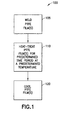
FIG. 1 is a flow-chart depicting an exemplary method for heat treating PTFE films. -
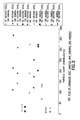
FIG. 2 is a dot plot of annealed test samples and controls that illustrate effects, in terms of particle count, of heat treating on PTFE liners; -
FIG. 3 is a dot plot of distilled water testing of control and annealed liners with one and five inversions; -
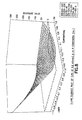
FIG. 4 is a calculated plot, based on actual data, showing how a particle count varies with heat treatment temperature for a number of liners held at selected temperatures for about 20 hours; -
FIG. 5 is a calculated plot, based on actual data, showing how a standard deviation of a particle count varies with heat treatment temperature for the liners ofFIG. 4 ; -
FIG. 6 is a calculated plot, based on actual data, showing how a particle count varies with heat treatment temperature for a number of liners held at selected temperatures for about 95 hours; -
FIG. 7 is a calculated plot, based on actual data, showing how a standard deviation of a particle count varies with heat treatment temperature for the liners ofFIG. 6 ; -
FIG. 8 is a calculated plot, based on actual data, showing how a particle count varies with heat treatment temperature for a number of liners held at selected temperatures for 170 hours; -
FIG. 9 is a calculated plot, based on actual data, showing how a standard deviation of a particle count varies with heat treatment temperature for the liners ofFIG. 8 ; and -
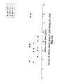
FIG. 10 is a dot plot of particle counts caused by heat treated PTFE liners. - As described above, conventional techniques for processing polytetrafluroethylene (PTFE) material such as PTFE liners result in relatively high particle counts and/or high standard deviation of those particle counts. That is, such PTFE material may be referred to as having a high particle count character. Embodiments of the present invention may be employed to reduce the particle count character of PTFE material. In fact, embodiments described herein may reduce the particle count character and the standard deviation thereof by factors greater than about ten. It should be noted that particle counting systems may also count "microbubbles" or other anomalies as "particles" accounted for in establishing a particle count or the particle count character of a material. The term "particle," as used herein, is intended to encompass whatever can be construed to be a "particle" by a conventional particle counting system.
- Referring now to
FIG. 1 , amethod 100 is shown for heat treating PTFE films in order to reduce particulate shedding.Method 100 may be employed where PTFE films are to be placed in contact with liquid substances. Themethod 100 may be used whenever particle count reduction is desirable. This may also include situations where PTFE films are to contact non-liquids such as substances. - In
step 105, a PTFE film is welded. This step is optional. In general, however, most liners made of PTFE will be welded. Welding for PTFE films is a process that melts and joins separate PTFE film portions generally under an amount of pressure. As described in more detail below, welding occurs at about the melting point of the particular PTFE film employed. - Accordingly, in one embodiment, welding may include exposing the PTFE films to between about 370C and about 430C for between about 5 and about 15 seconds. A pressure of between about 60 psi and about 100 psi may be applied. Additionally, the PTFE films may be cooled for between about 5 and about 15 seconds at a constant pressure before further processing as described below.
- Usually, the PTFE film is a heat processable PTFE fluoropolymer however, any PTFE may be employed. The welding described above produces one or more heat affected zones which, left untreated may be prone to contribute to particle shedding. However, as described further herein, the heat affected zones and PTFE film generally may be treated to reduce such occurrence.
- A heat affected zone is caused by heating the PTFE film to temperatures near or at, the melting point of the molecular components in the film. Generally, a heat affected zone is caused by heating the PTFE film to within about 15°C of the melting point of the PTFE film. Portions of the film tend to melt at different temperatures. For example, crystalline portions of the film may melt at temperatures higher than the melting temperature associated with the PTFE film, while amorphous portions of the film may melt at temperatures lower than the melting temperature associated with the PTFE film. Thus, a heat affected zone may be created even if the melting temperature associated with the PTFE film is never actually reached. Additionally, in order to completely weld two pieces of PTFE film together, at least the melting point of the PTFE films should be reached and temperatures somewhat above the melting point may be beneficial. Heat affected zones are beneficially affected by the processes of the present invention, as is PTFE film without heat affected zones.
- Generally,
step 105 includes multiple welding steps, such that a complete PTFE liner is formed. As described above, a PTFE liner is usually a four-sided, two-dimensional bag with a spout called a fitment. The spout is also welded onto the liner. Thus, step 105 will generally include several welding steps. - With continued reference to
Fig. 1 , and as described above, instep 110, one or more PTFE films may be heat treated by placing the films at a predetermined temperature for a predetermined time period. In this manner, particle shedding and particle counts, as described above, may be minimized. There are a number of different temperatures and time periods that may be beneficial, but there are certain temperatures and time periods that show particular benefit. Particular techniques for determining an optimum temperature and time period are described in reference toFIGS. 2 through 10 . Temperatures above the glass transition temperature of the material (about 130°C for many PTFE films) will begin to produce lower particulate shedding, as shown in more detail below. The heat treating process becomes particularly effective as temperatures exceeding 150°C are applied. As shown in more detail below, even higher temperatures are beneficial, until an optimal temperature is reached, but too high of a temperature can lead to increased particulate shedding as compared to the optimum temperature. Nonetheless, temperatures higher than the optimum temperature can be used if desired, as particle shedding may still be decreased with higher temperatures. - Generally, the predetermined temperature in
step 110 is above about 150 degrees centigrade (C), more preferably above about 200°C, and most preferably about 228°C. Higher temperatures may also be used. It is preferable that temperatures be less than about 260°C. It should also be noted that a temperature range, such as 230°C ± 20°C, may be used. Additionally, films may be applied in a discontinuous or periodic manner. That is the PTFE material may be heated to the predetermined temperature and cooled to, for instance, room temperature, then reheated to the initial predetermined temperature. However, in order to minimize total treatment time, the PTFE films may be continuously maintained or an alternate elevated temperature at the predetermined temperature for a particular time period, as reheating and cooling makes the total time required to heat treat PTFE films longer. - Concerning the predetermined time period, as shown in more detail below, a recommended time period is greater than about 20 hours, a more preferred time period is greater than 50 hours and a most preferred time period is about 100 hours. While shorter or longer time periods may be used, a time period of about 100 hours, as determined through the techniques given below, should provide the smallest amount of particulate shedding and the standard deviation thereof in the shortest time period. It should be noted that
step 100 can take place afterstep 120, if desired. - Now that an overview of exemplary heat treatment techniques for PTFE films has been described, techniques for determining appropriate temperature and time periods for any particular PTFE film or, more likely, set of PTFE films will be described.
- Referring now to
FIG. 2 , a dot plot of annealed test samples and controls is shown. This plot illustrate effects, in terms of particle count, of heat treating on PTFE liners. PTFE liners were filled with photoresist, inverted five times and counted at 0.2 microns 16 hrs after filling. The x-axis units are particles per milliliter (particles/ml) at 0.2 microns. The legend at the right ofFig. 2 contains a description of each set of samples tested. Each sample in a set of samples was a number of heat processable PTFE fluoropolymer films that were welded together into a liner. In this example, there are three PTFE liners per set. The welds were performed by using a welding machine that presses two PTFE films together, along a relatively thin line or set of lines, for a predetermined time at a predetermined temperature, where the predetermined temperature is equal to or greater than the melting point of the PTFE films. The "10 second cool" is a 10 second period of time used to cool the welded PTFE films to a predetermined cool temperature. Similarly, the "40 second cool" is a 40 second period of time used to cool the welded PTFE films to a predetermined cool temperature. - The samples, as shown in legend, were as follows: (1) a test set of PTFE liners with a 10-second cool followed by a 180°C heat treat for four days; (2) a test set of PTFE liners with a 40-second cool followed by a 180°C heat treat for four days; (3) a test set of PTFE liners with a 10-second cool followed by a 120°C heat treat for four days; (4) a test set of PTFE liners with a 40-second cool followed by a 120°C heat treat for four days; (5) a control set of PTFE liners with welds produced with a 10-second cool; (6) a test set of PTFE liners with welds produced with 40-second cool; (7) a test set of PTFE liners with a 180°C heat treat for four days followed by a 10-second re-weld and a 40-second cool; (8) a test set of PTFE liners with a 180°C heat treat for four days followed by 40-second re-weld and a 10-second cool; (9) a test set of PTFE liners with a 120C heat treat for four days followed by a 10-second re-weld and a 40-second cool; and (10) a test set of PTFE liners with a 120°C heat treat for four days followed by 40-second re-weld and a 10-second cool.
- The dots plotted for each set of PTFE liners in
FIG. 2 are allotted their own row in the figure. For instance, the dots plotted for the set entitled "10 second cool, 180° anneal" are shown on the row nearest the axis for particle count. Similarly, the dots plotted for the set entitled "40 second cool, 180° anneal" are shown on the second row from the axis for particle count. -
FIG. 2 shows, among other things, that the effect of the amount of cooling time after welding is minimal, and the 180°C anneal produces PTFE liners having the lowest particle count for the temperatures selected. - Because the amount of agitation (i.e., inverting a filled PTFE liner five times) used in
FIG. 2 is not typical in quality control testing, and because particle counts are generally taken using distilled water, samples were prepared to measure the effects of heat treatment on PTFE liners that were tested in DI water with one and five inversions. The heat treatment was performed at 180°C for five days. The sample PTFE liners were filled and particle tested with one hour of filling at 0.2 microns. The results are shown inFIG. 3 , which is a dot plot of distilled water testing of control and annealed liners.FIG. 3 shows, among other things, that the annealed PTFE liners cause smaller particle counts than the corresponding control PTFE liners. - To determine the optimum settings for liner heat treatment, it is beneficial to select PTFE liners from a number of lots of liners. PTFE liners from each liner lot can then be heated for different time periods and for different temperatures. Thus, "sets" can be determined, where each set has a number of PTFE liners from certain lots, a selected temperature and a selected time period. The particle counts, for a chosen number of inversions of the PTFE liners, are then determined for the sets of liners and a regression analysis on the particle counts will determine an "optimal" temperature and "optimal" time period. The optimal values are theoretical and may differ slightly from an actual "optimal" temperature or time period. An example of this "optimization" technique follows.
- Sample PTFE liners were prepared from three lots of liners. Each liner lot was heated for 20, 95, or 170 hours at 180°C, 220°C, or 260°C. Sample PTFE liners were filled with photoresist, inverted five times and particle counted at 0.2 microns at 16 hrs after filling.
- Based on the results of the optimization technique for the three lots of liners tested, it appears that liner lot and heat treating temperature are the biggest contributors to particle levels and particle level variability, as indicated by the standard deviation. It appears that the relationships between liner lot, heat treating temperature, particle levels and standard deviation thereof are nonlinear with several second order interactions. If time is held constant at 20 hours, the liner lot and temperature curves (for particle count) look like what is shown in
FIG. 4 . -
FIG. 4 is a calculated plot, based on actual data, showing how a particle count varies with heat treatment temperature for a number of liners held at a selected temperature for 20 hours. In the example ofFIG. 4 , actual data from different temperatures and liner lots were determined and placed into a program that used the data to determine the plot shown inFIG. 4 . Thus, the plot shown inFIG. 4 is calculated based on actual data. - Regarding the temperatures shown in
FIG. 4 , the temperatures are as follows: -1 is equivalent to 180°C; 0 is equivalent to 220°C; and 1 is equivalent to 260C. The response value is the particle count, in particles/ml. Fifteen PTFE liners were used from three different liner lots (lots FIG. 4 reaches a low at about 236°C (0.4times 40 plus 220°C), although this varies somewhat with liner lot. -
FIG. 5 is a calculated plot, based on actual data, showing how a standard deviation of a particle count varies with heat treatment temperature for the liners used inFIG. 4 . The temperatures, response values, and liner lots are the same as inFIG. 4 . As withFIG. 4 , the plot inFIG. 5 is calculated using actual data, and the data is the same used inFIG. 4 .FIG. 5 shows that standard deviation of particle count is affected by heat treatment and reaches a low at about 244°C (0.6times 40 plus 220°C), depending on liner lot. -
FIG. 6 is a calculated plot showing how a particle count varies with heat treatment temperature for a number of liners held at a selected temperature for 95 hours.FIG. 6 is a plot generated through the same techniques used in regard toFIG. 4 : fifteen PTFE liners, five from three different lots, were used and the resultant data from different temperatures and liner lots were determined and placed into a program that used the data to determine the plot shown inFIG. 6. FIG. 6 shows that particle count varies with temperate and liner lot. -
FIG. 7 is a calculated plot showing how a standard deviation of a particle count varies with heat treatment temperature for the liners used inFIG. 6 .FIG. 7 shows that the standard deviation of particle count varies with temperature and liner lot. -
FIG. 8 is a plot calculated through techniques used to determineFIGS. 4 and6 but based on a number of liners held at a selected temperature for 170 hours. It should be noted that the negative values of particle count are calculated and not observed.FIG. 9 is a plot calculated through techniques used to determineFIGS. 5 and7 but calculated using the liners ofFIG. 8 . BothFIGS. 8 and9 show that particle count and the standard deviation thereof, respectively, vary with temperature and liner lot. - Thus,
FIGS. 4 through 9 show that particle count and the standard deviation thereof, respectively, vary with temperature and liner lot. In order to determine an optimum temperature and time period, a regression analysis is used on the determined data. The regression analysis of the data used to determineFIGS. 4 through 9 indicates that, to minimize particle levels and standard deviation at 0.2 microns, the temperature should be 228C for a time period of 100 hrs. - These values were used for a confirmation experiment where three lots of liners were heated treated for 100 hrs at 228°C. The results of the testing (five inversions in photoresist, 16hr rest with particle counting) are shown in
FIG. 10. FIG. 10 is a dot plot of particle counts caused by heat treated PTFE liners. As can be seen byFIG. 10 , the particle count and standard deviation thereof are small for heat treated PTFE liners. Thus, the present invention can reduce particle counts from about 250±100 particles/ml to about 8±2 particles/ml. - Note that liner lot variability, in terms of the standard deviation of the particle count, is also reduced. While there is still some variability, as the third liner lot has a few sample PTFE liners with particle counts greater than 10, the variability has been markedly decreased.
- It is to be understood that the embodiments and variations shown and described herein are merely illustrative of the principles of this invention and that various modifications may be implemented by those skilled in the art without departing from the scope and spirit of the invention. In addition, the various assumptions made herein are for the purposes of simplicity and clarity of illustration, and should not be construed as requirements of the present invention.
- Further embodiments of the invention are as follows:
- Embodiment 1: A method comprising:
- heating a polytetrafluoroethylene material to an elevated temperature; and maintaining said heating for a time sufficient to substantially reduce a particle count character of the polytetrafluroethylene material.
- Embodiment 2: The method of
embodiment 1 further comprising applying a melting temperature to a portion of the polytetrafluoroethylene material for welding thereof prior to said heating. - Embodiment 3: The method of
embodiment 2 wherein the melting temperature is within about 15°C of a melting point of the polytetrafluoroethylene material. - Embodiment 4: The method of
embodiment 2 wherein said applying forms a heat affected zone of the portion, said heating and said maintaining to affect the heat affected zone. - Embodiment 5: The method of
embodiment 1 wherein the elevated temperature is above a glass transition temperature of the polytrafluororethylene material. - Embodiment 6: The method of
embodiment 1 wherein the elevated temperature is between about 130°C and about 260°C. - Embodiment 7: The method of
embodiment 1 wherein the time is between about 20 hours and about 100 hours. - Embodiment 8: The method of
embodiment 1 wherein said maintaining occurs in a periodic manner comprising: - cooling the polytetrafluoroethylene material; and reheating the polytetrafluoroethylene material.
- Embodiment 9: The method of
embodiment 1 wherein said maintaining occurs in a periodic manner comprising: - cooling the polytetrafluoroethylene material; and
- reheating the polytetrafluoroethylene material.
- Embodiment 10: A method comprising heating a polytetrafluoroethylene material to about 228°C for a sufficient time to substantially reduce a particle count character thereof.
- Embodiment 11: The method of
embodiment 10 wherein said heating is for about 100 hours. - Embodiment 12: A polytetrafluoroethylene material having a particle count character reduced by application of an elevated temperature thereto.
- Embodiment 13: The polytetrafluoroethylene material of
embodiment 12 wherein the elevated temperature is between about 130° and about 260°C. - Embodiment 14: The polytetrafluoroethylene material of
embodiment 12 wherein the application of the elevated temperature is for between about 20 hours and about 100 hours. - Embodiment 15: The polytetrafluoroethylene material of
embodiment 12 wherein the elevated temperature is about 228°C and the application is for about 100 hours. - Embodiment 16: The polytetrafluoroethylene material of
embodiment 12 in the form of a film for contacting a substance. - Embodiment 17: The polytetrafluoroethylene material of
embodiment 16 wherein the substance is one of a liquid and a powder. - Embodiment 18: The polytetrafluoroethylene material of embodiment 17 wherein the film is incorporated a package to contain the substance.
Claims (15)
- A method comprising:heating a polytetrafluoroethylene material to an elevated temperature of between 130°C and 260°C;maintaining said heating to substantially reduce a count of particles shed by the polytetrafluoroethylene material; andfabricating a liner comprising the polytetrafluoroethylene material, said liner being adapted to contain an ultra-pure substance.
- A method according to claim 1, wherein said heating is maintained for a period of at least 20 hours.
- A method according to any one of claims 1 or 2, wherein the polytetrafluoroethylene material comprises polytetrafluoroethylene film.
- A method according to claim 3, wherein the polytetrafluoroethylene film is formed by planing of a layer of material from a polytetrafluoroethylene billet.
- A method according to claim 1, wherein said fabricating of the liner comprises welding of the polytetrafluoroethylene material.
- A method according to claim 5, wherein said maintaining of heating occurs after said welding.
- A method according to claim 1, wherein said maintaining of heating occurs in a periodic manner including cooling the polytetrafluoroethylene material and reheating the polytetrafluoroethylene material.
- A method according to claim 1, further comprising joining a fitment to the liner by welding.
- A method according to claim 1, wherein the polytetrafluoroethylene material is substantially inert and non-reactive with an ultra-pure substance to be stored in the liner.
- A method according to any one of claims 1 to 10, wherein the count of particles shed by the polytetrafluoroethylene material is below 10 particles/ml.
- A method according to any one of claims 1 to 10, wherein the count of particles shed by the polytetrafluoroethylene material is reduced by a factor of 10 relative to a particle count value prior to said reduction.
- A method according to any one of claims 1 to 10 wherein said elevated temperature is in a range of from 150°C to 250°C, said time is greater than 20 hours.
- A method according to claim 1, further comprising inserting the liner into a bottle to form a polytetrafluoroethylene-lined bottle.
- A method according to any one of claims 1 to 13, comprising filling the liner with a semiconductor processing chemical.
- A liner comprising polytetrafluoroethylene material and obtainable by a method according to any one of claims 1 to 12.
Applications Claiming Priority (2)
| Application Number | Priority Date | Filing Date | Title |
|---|---|---|---|
| US10/606,521 US7067616B2 (en) | 2003-06-26 | 2003-06-26 | Polytetrafluoroethylene treatment |
| EP04755897A EP1636276A4 (en) | 2003-06-26 | 2004-06-23 | Polytetrafluoroethylene treatment |
Related Parent Applications (2)
| Application Number | Title | Priority Date | Filing Date |
|---|---|---|---|
| EP04755897A Division EP1636276A4 (en) | 2003-06-26 | 2004-06-23 | Polytetrafluoroethylene treatment |
| EP04755897.8 Division | 2004-06-23 |
Publications (2)
| Publication Number | Publication Date |
|---|---|
| EP2418226A1 true EP2418226A1 (en) | 2012-02-15 |
| EP2418226B1 EP2418226B1 (en) | 2015-07-22 |
Family
ID=33540088
Family Applications (2)
| Application Number | Title | Priority Date | Filing Date |
|---|---|---|---|
| EP11182270.6A Expired - Lifetime EP2418226B1 (en) | 2003-06-26 | 2004-06-23 | Polytetrafluoroethylene treatment |
| EP04755897A Ceased EP1636276A4 (en) | 2003-06-26 | 2004-06-23 | Polytetrafluoroethylene treatment |
Family Applications After (1)
| Application Number | Title | Priority Date | Filing Date |
|---|---|---|---|
| EP04755897A Ceased EP1636276A4 (en) | 2003-06-26 | 2004-06-23 | Polytetrafluoroethylene treatment |
Country Status (8)
| Country | Link |
|---|---|
| US (2) | US7067616B2 (en) |
| EP (2) | EP2418226B1 (en) |
| JP (2) | JP4842810B2 (en) |
| KR (2) | KR101110897B1 (en) |
| CN (2) | CN1813005B (en) |
| MY (1) | MY142028A (en) |
| TW (1) | TWI352712B (en) |
| WO (1) | WO2005003189A1 (en) |
Families Citing this family (15)
| Publication number | Priority date | Publication date | Assignee | Title |
|---|---|---|---|---|
| US7067616B2 (en) * | 2003-06-26 | 2006-06-27 | Advanced Technology Materials, Inc. | Polytetrafluoroethylene treatment |
| US20050050854A1 (en) * | 2003-09-09 | 2005-03-10 | Jean-Pascal Zambaux | Sterile, pyrogen-free, polymeric film-based heating bag |
| CN100383187C (en) * | 2005-08-29 | 2008-04-23 | 山东东岳高分子材料有限公司 | Method for manufacturing polytetrafluoroethylene free-flow granulate with recyclable solvent |
| US9062828B2 (en) | 2010-10-27 | 2015-06-23 | Advanced Technology Materials, Inc. | Liner-based assembly for removing impurities |
| TW201242670A (en) | 2010-11-23 | 2012-11-01 | Advanced Tech Materials | Liner-based dispenser |
| WO2013123378A1 (en) | 2012-02-17 | 2013-08-22 | Advanced Technology Materials, Inc. | Polymer-based multilayer gas barrier film |
| KR20140130704A (en) | 2012-02-24 | 2014-11-11 | 어드밴스드 테크놀러지 머티리얼즈, 인코포레이티드 | Fluid delivery system and method |
| US9517873B1 (en) | 2012-09-28 | 2016-12-13 | Air Liquide Electronics U.S. Lp | Clean storage packaging article and method for making and using |
| EP3057884B1 (en) | 2013-10-18 | 2018-07-04 | Entegris, Inc. | Dip tube assemblies and methods of manufacturing the same |
| EP3074320A4 (en) | 2013-11-26 | 2017-08-02 | Entegris, Inc. | Fitment and fitment adapter for dispensing systems and methods for manufacturing same |
| JP6754695B2 (en) | 2014-03-17 | 2020-09-16 | インテグリス・インコーポレーテッド | Disposable liquid chemical sensor system |
| EP3152040A1 (en) * | 2014-06-05 | 2017-04-12 | Solvay Specialty Polymers Italy S.p.A. | Melt-processable perfluoropolymers having improved thermal and mechanical properties after heating treatment |
| EP3206969A4 (en) | 2014-10-17 | 2018-05-30 | Entegris, Inc. | Packaging for dip tubes |
| EP4150045A1 (en) | 2020-05-12 | 2023-03-22 | PBS Biotech, Inc. | Material transfer devices and related systems and methods |
| WO2023108109A1 (en) * | 2021-12-10 | 2023-06-15 | Saint-Gobain Performance Plastics Corporation | Polymer composition and methods of making and using the same |
Citations (3)
| Publication number | Priority date | Publication date | Assignee | Title |
|---|---|---|---|---|
| GB989513A (en) * | 1961-05-24 | 1965-04-22 | W. R. Grace & Co. | |
| EP0515030A1 (en) * | 1991-04-17 | 1992-11-25 | Du Pont-Mitsui Fluorochemicals Co., Ltd | Tetrafluoroethylene copolymer resin powder composition and process for manufacture thereof |
| JPH10202803A (en) * | 1997-01-20 | 1998-08-04 | Nippon Valqua Ind Ltd | Production of laminated sheet and apparatus for producing laminated sheet |
Family Cites Families (26)
| Publication number | Priority date | Publication date | Assignee | Title |
|---|---|---|---|---|
| US944836A (en) * | 1908-04-18 | 1909-12-28 | John A Williams | Artificial tooth. |
| US2893900A (en) * | 1956-01-09 | 1959-07-07 | Eugene S Machlin | Process of condensing polytetrafluoroethylene vapors onto a substrate and sintering the condensate |
| BE619766A (en) * | 1961-07-13 | |||
| US3432511A (en) * | 1961-11-07 | 1969-03-11 | Duriron Co | Processing of plastic materials |
| GB1470850A (en) * | 1972-12-01 | 1977-04-21 | Allied Chem | Moulding poder |
| JPS49113874A (en) * | 1973-03-02 | 1974-10-30 | ||
| US4220511A (en) * | 1979-03-12 | 1980-09-02 | Radiation Dynamics, Inc. | Treatment of sintered poly-tetrafluoroethylene with irradiation and heat to produce a grindable material |
| DE3425027A1 (en) * | 1983-07-08 | 1985-01-17 | Sumitomo Electric Industries, Ltd., Osaka | FLUORINE RESIN FILTER |
| JPH01232013A (en) * | 1987-03-27 | 1989-09-18 | Asahi Chem Ind Co Ltd | Polytetrafluoroethylene polymer molding |
| US4948641A (en) * | 1987-06-01 | 1990-08-14 | Olin Corporation | Multiple layer container for storage of high purity chemicals |
| US5235995A (en) * | 1989-03-27 | 1993-08-17 | Semitool, Inc. | Semiconductor processor apparatus with dynamic wafer vapor treatment and particulate volatilization |
| US5215662A (en) * | 1988-12-16 | 1993-06-01 | Micron Separations Inc. | Heat resistant microporous material production and products |
| JPH085140B2 (en) * | 1989-09-26 | 1996-01-24 | ダイキン工業株式会社 | Fluororesin processing method |
| JPH0767749B2 (en) * | 1991-07-04 | 1995-07-26 | ニチアス株式会社 | Method for manufacturing soft fluororesin sheet |
| CA2074349C (en) * | 1991-07-23 | 2004-04-20 | Shinji Tamaru | Polytetrafluoroethylene porous film and preparation and use thereof |
| JP3386174B2 (en) * | 1993-04-09 | 2003-03-17 | 忠弘 大見 | Method for smoothing fluororesin molded article and smooth molded article |
| US6159565A (en) * | 1993-08-18 | 2000-12-12 | W. L. Gore & Associates, Inc. | Thin-wall intraluminal graft |
| CA2187633A1 (en) * | 1994-04-11 | 1995-10-19 | Douglas R. Chambers | Superabsorbent polymers and products therefrom |
| JP3003500B2 (en) * | 1994-04-28 | 2000-01-31 | ダイキン工業株式会社 | Polytetrafluoroethylene composite porous membrane |
| JPH1135709A (en) * | 1997-07-16 | 1999-02-09 | Daikin Ind Ltd | Method for smoothing fired polytetrafluoroethylene sheet |
| US6218015B1 (en) * | 1998-02-13 | 2001-04-17 | World Properties, Inc. | Casting mixtures comprising granular and dispersion fluoropolymers |
| JPH11226850A (en) * | 1998-02-16 | 1999-08-24 | Yanagawa Seiko Kk | Blade tape member and blade tape using it |
| US6737165B1 (en) * | 1998-08-06 | 2004-05-18 | Omlidon Technologies Llc | Melt-processible poly(tetrafluoroethylene) |
| JP2000229388A (en) * | 1999-02-09 | 2000-08-22 | Du Pont Mitsui Fluorochem Co Ltd | Hot-melt fluoroplastic-coated polytetrafluoroethylene molded object |
| CN1256988C (en) * | 2002-03-18 | 2006-05-24 | 上海南洋医用材料有限公司 | Handling method of film material for treating injury of the bone |
| US7067616B2 (en) | 2003-06-26 | 2006-06-27 | Advanced Technology Materials, Inc. | Polytetrafluoroethylene treatment |
-
2003
- 2003-06-26 US US10/606,521 patent/US7067616B2/en not_active Expired - Fee Related
-
2004
- 2004-06-03 MY MYPI20042139A patent/MY142028A/en unknown
- 2004-06-16 TW TW93117270A patent/TWI352712B/en not_active IP Right Cessation
- 2004-06-23 EP EP11182270.6A patent/EP2418226B1/en not_active Expired - Lifetime
- 2004-06-23 EP EP04755897A patent/EP1636276A4/en not_active Ceased
- 2004-06-23 CN CN2004800178174A patent/CN1813005B/en not_active Expired - Lifetime
- 2004-06-23 KR KR1020057024901A patent/KR101110897B1/en not_active Expired - Lifetime
- 2004-06-23 CN CN201210112290.XA patent/CN102659962B/en not_active Expired - Lifetime
- 2004-06-23 WO PCT/US2004/020024 patent/WO2005003189A1/en not_active Ceased
- 2004-06-23 KR KR1020117015544A patent/KR101173811B1/en not_active Expired - Lifetime
- 2004-06-23 JP JP2006517550A patent/JP4842810B2/en not_active Expired - Fee Related
-
2006
- 2006-06-13 US US11/452,153 patent/US7335721B2/en not_active Expired - Lifetime
-
2010
- 2010-10-18 JP JP2010233441A patent/JP5369074B2/en not_active Expired - Lifetime
Patent Citations (3)
| Publication number | Priority date | Publication date | Assignee | Title |
|---|---|---|---|---|
| GB989513A (en) * | 1961-05-24 | 1965-04-22 | W. R. Grace & Co. | |
| EP0515030A1 (en) * | 1991-04-17 | 1992-11-25 | Du Pont-Mitsui Fluorochemicals Co., Ltd | Tetrafluoroethylene copolymer resin powder composition and process for manufacture thereof |
| JPH10202803A (en) * | 1997-01-20 | 1998-08-04 | Nippon Valqua Ind Ltd | Production of laminated sheet and apparatus for producing laminated sheet |
Non-Patent Citations (1)
| Title |
|---|
| DATABASE WPI Week 199841, Derwent World Patents Index; AN 1998-475691, XP002663994 * |
Also Published As
| Publication number | Publication date |
|---|---|
| KR101173811B1 (en) | 2012-08-16 |
| EP1636276A4 (en) | 2009-07-01 |
| US7067616B2 (en) | 2006-06-27 |
| US20040266986A1 (en) | 2004-12-30 |
| JP2011046955A (en) | 2011-03-10 |
| EP1636276A1 (en) | 2006-03-22 |
| WO2005003189A1 (en) | 2005-01-13 |
| US7335721B2 (en) | 2008-02-26 |
| JP4842810B2 (en) | 2011-12-21 |
| US20060235197A1 (en) | 2006-10-19 |
| TWI352712B (en) | 2011-11-21 |
| MY142028A (en) | 2010-08-16 |
| CN1813005A (en) | 2006-08-02 |
| EP2418226B1 (en) | 2015-07-22 |
| TW200504126A (en) | 2005-02-01 |
| CN102659962A (en) | 2012-09-12 |
| CN1813005B (en) | 2012-06-20 |
| KR20110095401A (en) | 2011-08-24 |
| JP2007524725A (en) | 2007-08-30 |
| JP5369074B2 (en) | 2013-12-18 |
| KR20060031642A (en) | 2006-04-12 |
| KR101110897B1 (en) | 2012-02-20 |
| WO2005003189B1 (en) | 2005-02-03 |
| CN102659962B (en) | 2015-04-22 |
Similar Documents
| Publication | Publication Date | Title |
|---|---|---|
| JP5369074B2 (en) | Polytetrafluoroethylene treatment | |
| DE3752054T2 (en) | Sealable plastic composite film | |
| AU762386B2 (en) | Method of producing metal composites which can be processed at high temperatures | |
| EP0462047B1 (en) | Process and apparatus for the formation of surface layers on articles and articles with a surface layer formed according to this process | |
| KR20010088786A (en) | Polytetrafluoroethylene laminate | |
| EP4299638A2 (en) | Melt processible fluororesin molded article | |
| CA1097992A (en) | Amorphous alloy razor blade | |
| JP2002036237A (en) | Method for producing recycled fluororesin and recycled fluororesin | |
| DE69827600T2 (en) | POLYESTER FILM | |
| JPH08245723A (en) | Water repellent resin and method for adjusting the same | |
| JP7618658B2 (en) | Fluid System Components | |
| JPH0474844A (en) | Aluminum foil for packaging | |
| JP2017206592A (en) | Fluoropolymer molded product manufacturing method | |
| Lazo et al. | Morphology development during phase inversion in isothermal, model experiments: steady simple-shear and quiescent flow fields | |
| DE19914752A1 (en) | Thermal treatment of catalyst material for polyolefin production involves discontinuous activation and/or calcination by heating, tempering and then cooling outside the reactor, with a constant reactor temperature | |
| CN103397224A (en) | Alloy zinc shots and manufacturing method thereof | |
| EP4438632A1 (en) | Polyvinylidene fluoride for high purity water supply applications | |
| Mannan et al. | Solder paste reflow modeling for flip chip assembly | |
| Kang et al. | Effect of Reflow Parameters on Solder Wetting | |
| EP1084176A1 (en) | Locally providing a coated article with a sealing material | |
| Suess | Failure Analysis of Welded Low-Carbon Steel Storage Tank | |
| Weltsch et al. | THE EFFECT OF REFLOW ON WETTABILITY OF Sn 96.5 Ag 3 Cu 0.5 SOLDER. | |
| JP2015086105A (en) | Method of cleaning silicon | |
| JP2007069524A (en) | Manufacturing method of biaxially stretched polyester film for twist wrapping |
Legal Events
| Date | Code | Title | Description |
|---|---|---|---|
| AC | Divisional application: reference to earlier application |
Ref document number: 1636276 Country of ref document: EP Kind code of ref document: P |
|
| AK | Designated contracting states |
Kind code of ref document: A1 Designated state(s): AT BE BG CH CY CZ DE DK EE ES FI FR GB GR HU IE IT LI LU MC NL PL PT RO SE SI SK TR |
|
| PUAI | Public reference made under article 153(3) epc to a published international application that has entered the european phase |
Free format text: ORIGINAL CODE: 0009012 |
|
| 17P | Request for examination filed |
Effective date: 20120809 |
|
| 17Q | First examination report despatched |
Effective date: 20120906 |
|
| GRAP | Despatch of communication of intention to grant a patent |
Free format text: ORIGINAL CODE: EPIDOSNIGR1 |
|
| RIC1 | Information provided on ipc code assigned before grant |
Ipc: B29C 63/00 20060101ALI20141215BHEP Ipc: C08J 7/00 20060101ALI20141215BHEP Ipc: C08F 6/00 20060101AFI20141215BHEP |
|
| INTG | Intention to grant announced |
Effective date: 20150109 |
|
| GRAS | Grant fee paid |
Free format text: ORIGINAL CODE: EPIDOSNIGR3 |
|
| GRAA | (expected) grant |
Free format text: ORIGINAL CODE: 0009210 |
|
| AC | Divisional application: reference to earlier application |
Ref document number: 1636276 Country of ref document: EP Kind code of ref document: P |
|
| AK | Designated contracting states |
Kind code of ref document: B1 Designated state(s): AT BE BG CH CY CZ DE DK EE ES FI FR GB GR HU IE IT LI LU MC NL PL PT RO SE SI SK TR |
|
| REG | Reference to a national code |
Ref country code: GB Ref legal event code: FG4D |
|
| REG | Reference to a national code |
Ref country code: CH Ref legal event code: EP |
|
| REG | Reference to a national code |
Ref country code: IE Ref legal event code: FG4D |
|
| REG | Reference to a national code |
Ref country code: AT Ref legal event code: REF Ref document number: 737871 Country of ref document: AT Kind code of ref document: T Effective date: 20150815 |
|
| REG | Reference to a national code |
Ref country code: DE Ref legal event code: R096 Ref document number: 602004047552 Country of ref document: DE |
|
| REG | Reference to a national code |
Ref country code: AT Ref legal event code: MK05 Ref document number: 737871 Country of ref document: AT Kind code of ref document: T Effective date: 20150722 |
|
| REG | Reference to a national code |
Ref country code: NL Ref legal event code: MP Effective date: 20150722 |
|
| PG25 | Lapsed in a contracting state [announced via postgrant information from national office to epo] |
Ref country code: GR Free format text: LAPSE BECAUSE OF FAILURE TO SUBMIT A TRANSLATION OF THE DESCRIPTION OR TO PAY THE FEE WITHIN THE PRESCRIBED TIME-LIMIT Effective date: 20151023 Ref country code: FI Free format text: LAPSE BECAUSE OF FAILURE TO SUBMIT A TRANSLATION OF THE DESCRIPTION OR TO PAY THE FEE WITHIN THE PRESCRIBED TIME-LIMIT Effective date: 20150722 |
|
| PG25 | Lapsed in a contracting state [announced via postgrant information from national office to epo] |
Ref country code: SE Free format text: LAPSE BECAUSE OF FAILURE TO SUBMIT A TRANSLATION OF THE DESCRIPTION OR TO PAY THE FEE WITHIN THE PRESCRIBED TIME-LIMIT Effective date: 20150722 Ref country code: PT Free format text: LAPSE BECAUSE OF FAILURE TO SUBMIT A TRANSLATION OF THE DESCRIPTION OR TO PAY THE FEE WITHIN THE PRESCRIBED TIME-LIMIT Effective date: 20151123 Ref country code: AT Free format text: LAPSE BECAUSE OF FAILURE TO SUBMIT A TRANSLATION OF THE DESCRIPTION OR TO PAY THE FEE WITHIN THE PRESCRIBED TIME-LIMIT Effective date: 20150722 Ref country code: PL Free format text: LAPSE BECAUSE OF FAILURE TO SUBMIT A TRANSLATION OF THE DESCRIPTION OR TO PAY THE FEE WITHIN THE PRESCRIBED TIME-LIMIT Effective date: 20150722 Ref country code: ES Free format text: LAPSE BECAUSE OF FAILURE TO SUBMIT A TRANSLATION OF THE DESCRIPTION OR TO PAY THE FEE WITHIN THE PRESCRIBED TIME-LIMIT Effective date: 20150722 |
|
| REG | Reference to a national code |
Ref country code: DE Ref legal event code: R097 Ref document number: 602004047552 Country of ref document: DE |
|
| PG25 | Lapsed in a contracting state [announced via postgrant information from national office to epo] |
Ref country code: SK Free format text: LAPSE BECAUSE OF FAILURE TO SUBMIT A TRANSLATION OF THE DESCRIPTION OR TO PAY THE FEE WITHIN THE PRESCRIBED TIME-LIMIT Effective date: 20150722 Ref country code: EE Free format text: LAPSE BECAUSE OF FAILURE TO SUBMIT A TRANSLATION OF THE DESCRIPTION OR TO PAY THE FEE WITHIN THE PRESCRIBED TIME-LIMIT Effective date: 20150722 Ref country code: IT Free format text: LAPSE BECAUSE OF FAILURE TO SUBMIT A TRANSLATION OF THE DESCRIPTION OR TO PAY THE FEE WITHIN THE PRESCRIBED TIME-LIMIT Effective date: 20150722 Ref country code: DK Free format text: LAPSE BECAUSE OF FAILURE TO SUBMIT A TRANSLATION OF THE DESCRIPTION OR TO PAY THE FEE WITHIN THE PRESCRIBED TIME-LIMIT Effective date: 20150722 Ref country code: CZ Free format text: LAPSE BECAUSE OF FAILURE TO SUBMIT A TRANSLATION OF THE DESCRIPTION OR TO PAY THE FEE WITHIN THE PRESCRIBED TIME-LIMIT Effective date: 20150722 |
|
| REG | Reference to a national code |
Ref country code: FR Ref legal event code: PLFP Year of fee payment: 13 |
|
| PLBE | No opposition filed within time limit |
Free format text: ORIGINAL CODE: 0009261 |
|
| STAA | Information on the status of an ep patent application or granted ep patent |
Free format text: STATUS: NO OPPOSITION FILED WITHIN TIME LIMIT |
|
| PG25 | Lapsed in a contracting state [announced via postgrant information from national office to epo] |
Ref country code: RO Free format text: LAPSE BECAUSE OF FAILURE TO SUBMIT A TRANSLATION OF THE DESCRIPTION OR TO PAY THE FEE WITHIN THE PRESCRIBED TIME-LIMIT Effective date: 20150722 |
|
| 26N | No opposition filed |
Effective date: 20160425 |
|
| PG25 | Lapsed in a contracting state [announced via postgrant information from national office to epo] |
Ref country code: SI Free format text: LAPSE BECAUSE OF FAILURE TO SUBMIT A TRANSLATION OF THE DESCRIPTION OR TO PAY THE FEE WITHIN THE PRESCRIBED TIME-LIMIT Effective date: 20150722 |
|
| PG25 | Lapsed in a contracting state [announced via postgrant information from national office to epo] |
Ref country code: MC Free format text: LAPSE BECAUSE OF FAILURE TO SUBMIT A TRANSLATION OF THE DESCRIPTION OR TO PAY THE FEE WITHIN THE PRESCRIBED TIME-LIMIT Effective date: 20150722 |
|
| REG | Reference to a national code |
Ref country code: CH Ref legal event code: PL |
|
| REG | Reference to a national code |
Ref country code: IE Ref legal event code: MM4A |
|
| PG25 | Lapsed in a contracting state [announced via postgrant information from national office to epo] |
Ref country code: CH Free format text: LAPSE BECAUSE OF NON-PAYMENT OF DUE FEES Effective date: 20160630 Ref country code: LI Free format text: LAPSE BECAUSE OF NON-PAYMENT OF DUE FEES Effective date: 20160630 |
|
| REG | Reference to a national code |
Ref country code: FR Ref legal event code: PLFP Year of fee payment: 14 |
|
| PG25 | Lapsed in a contracting state [announced via postgrant information from national office to epo] |
Ref country code: IE Free format text: LAPSE BECAUSE OF NON-PAYMENT OF DUE FEES Effective date: 20160623 |
|
| PG25 | Lapsed in a contracting state [announced via postgrant information from national office to epo] |
Ref country code: NL Free format text: LAPSE BECAUSE OF FAILURE TO SUBMIT A TRANSLATION OF THE DESCRIPTION OR TO PAY THE FEE WITHIN THE PRESCRIBED TIME-LIMIT Effective date: 20150722 |
|
| REG | Reference to a national code |
Ref country code: FR Ref legal event code: PLFP Year of fee payment: 15 |
|
| PG25 | Lapsed in a contracting state [announced via postgrant information from national office to epo] |
Ref country code: CY Free format text: LAPSE BECAUSE OF FAILURE TO SUBMIT A TRANSLATION OF THE DESCRIPTION OR TO PAY THE FEE WITHIN THE PRESCRIBED TIME-LIMIT Effective date: 20150722 Ref country code: HU Free format text: LAPSE BECAUSE OF FAILURE TO SUBMIT A TRANSLATION OF THE DESCRIPTION OR TO PAY THE FEE WITHIN THE PRESCRIBED TIME-LIMIT; INVALID AB INITIO Effective date: 20040623 |
|
| PG25 | Lapsed in a contracting state [announced via postgrant information from national office to epo] |
Ref country code: TR Free format text: LAPSE BECAUSE OF FAILURE TO SUBMIT A TRANSLATION OF THE DESCRIPTION OR TO PAY THE FEE WITHIN THE PRESCRIBED TIME-LIMIT Effective date: 20150722 Ref country code: LU Free format text: LAPSE BECAUSE OF NON-PAYMENT OF DUE FEES Effective date: 20160623 |
|
| PG25 | Lapsed in a contracting state [announced via postgrant information from national office to epo] |
Ref country code: BG Free format text: LAPSE BECAUSE OF FAILURE TO SUBMIT A TRANSLATION OF THE DESCRIPTION OR TO PAY THE FEE WITHIN THE PRESCRIBED TIME-LIMIT Effective date: 20150722 |
|
| P01 | Opt-out of the competence of the unified patent court (upc) registered |
Effective date: 20230526 |
|
| PGFP | Annual fee paid to national office [announced via postgrant information from national office to epo] |
Ref country code: FR Payment date: 20230523 Year of fee payment: 20 Ref country code: DE Payment date: 20230523 Year of fee payment: 20 |
|
| PGFP | Annual fee paid to national office [announced via postgrant information from national office to epo] |
Ref country code: BE Payment date: 20230523 Year of fee payment: 20 |
|
| PGFP | Annual fee paid to national office [announced via postgrant information from national office to epo] |
Ref country code: GB Payment date: 20230523 Year of fee payment: 20 |
|
| REG | Reference to a national code |
Ref country code: DE Ref legal event code: R071 Ref document number: 602004047552 Country of ref document: DE |
|
| PG25 | Lapsed in a contracting state [announced via postgrant information from national office to epo] |
Ref country code: GB Free format text: LAPSE BECAUSE OF EXPIRATION OF PROTECTION Effective date: 20240622 |
|
| REG | Reference to a national code |
Ref country code: BE Ref legal event code: MK Effective date: 20240623 |
|
| REG | Reference to a national code |
Ref country code: GB Ref legal event code: PE20 Expiry date: 20240622 |
|
| PG25 | Lapsed in a contracting state [announced via postgrant information from national office to epo] |
Ref country code: GB Free format text: LAPSE BECAUSE OF EXPIRATION OF PROTECTION Effective date: 20240622 |