KR20140130704A - Fluid delivery system and method - Google Patents
Fluid delivery system and method Download PDFInfo
- Publication number
- KR20140130704A KR20140130704A KR1020147025812A KR20147025812A KR20140130704A KR 20140130704 A KR20140130704 A KR 20140130704A KR 1020147025812 A KR1020147025812 A KR 1020147025812A KR 20147025812 A KR20147025812 A KR 20147025812A KR 20140130704 A KR20140130704 A KR 20140130704A
- Authority
- KR
- South Korea
- Prior art keywords
- fluid
- canister
- pressure
- tote
- reservoir
- Prior art date
Links
Images


Classifications
-
- F—MECHANICAL ENGINEERING; LIGHTING; HEATING; WEAPONS; BLASTING
- F17—STORING OR DISTRIBUTING GASES OR LIQUIDS
- F17C—VESSELS FOR CONTAINING OR STORING COMPRESSED, LIQUEFIED OR SOLIDIFIED GASES; FIXED-CAPACITY GAS-HOLDERS; FILLING VESSELS WITH, OR DISCHARGING FROM VESSELS, COMPRESSED, LIQUEFIED, OR SOLIDIFIED GASES
- F17C9/00—Methods or apparatus for discharging liquefied or solidified gases from vessels not under pressure
-
- B—PERFORMING OPERATIONS; TRANSPORTING
- B67—OPENING, CLOSING OR CLEANING BOTTLES, JARS OR SIMILAR CONTAINERS; LIQUID HANDLING
- B67D—DISPENSING, DELIVERING OR TRANSFERRING LIQUIDS, NOT OTHERWISE PROVIDED FOR
- B67D7/00—Apparatus or devices for transferring liquids from bulk storage containers or reservoirs into vehicles or into portable containers, e.g. for retail sale purposes
- B67D7/02—Apparatus or devices for transferring liquids from bulk storage containers or reservoirs into vehicles or into portable containers, e.g. for retail sale purposes for transferring liquids other than fuel or lubricants
- B67D7/0238—Apparatus or devices for transferring liquids from bulk storage containers or reservoirs into vehicles or into portable containers, e.g. for retail sale purposes for transferring liquids other than fuel or lubricants utilising compressed air or other gas acting directly or indirectly on liquids in storage containers
- B67D7/0244—Apparatus or devices for transferring liquids from bulk storage containers or reservoirs into vehicles or into portable containers, e.g. for retail sale purposes for transferring liquids other than fuel or lubricants utilising compressed air or other gas acting directly or indirectly on liquids in storage containers by using elastic expandable bags
- B67D7/025—Apparatus or devices for transferring liquids from bulk storage containers or reservoirs into vehicles or into portable containers, e.g. for retail sale purposes for transferring liquids other than fuel or lubricants utilising compressed air or other gas acting directly or indirectly on liquids in storage containers by using elastic expandable bags specially adapted for transferring liquids of high purity
-
- B—PERFORMING OPERATIONS; TRANSPORTING
- B67—OPENING, CLOSING OR CLEANING BOTTLES, JARS OR SIMILAR CONTAINERS; LIQUID HANDLING
- B67D—DISPENSING, DELIVERING OR TRANSFERRING LIQUIDS, NOT OTHERWISE PROVIDED FOR
- B67D7/00—Apparatus or devices for transferring liquids from bulk storage containers or reservoirs into vehicles or into portable containers, e.g. for retail sale purposes
- B67D7/02—Apparatus or devices for transferring liquids from bulk storage containers or reservoirs into vehicles or into portable containers, e.g. for retail sale purposes for transferring liquids other than fuel or lubricants
- B67D7/0238—Apparatus or devices for transferring liquids from bulk storage containers or reservoirs into vehicles or into portable containers, e.g. for retail sale purposes for transferring liquids other than fuel or lubricants utilising compressed air or other gas acting directly or indirectly on liquids in storage containers
- B67D7/0266—Apparatus or devices for transferring liquids from bulk storage containers or reservoirs into vehicles or into portable containers, e.g. for retail sale purposes for transferring liquids other than fuel or lubricants utilising compressed air or other gas acting directly or indirectly on liquids in storage containers by gas acting directly on the liquid
- B67D7/0272—Apparatus or devices for transferring liquids from bulk storage containers or reservoirs into vehicles or into portable containers, e.g. for retail sale purposes for transferring liquids other than fuel or lubricants utilising compressed air or other gas acting directly or indirectly on liquids in storage containers by gas acting directly on the liquid specially adapted for transferring liquids of high purity
-
- B—PERFORMING OPERATIONS; TRANSPORTING
- B67—OPENING, CLOSING OR CLEANING BOTTLES, JARS OR SIMILAR CONTAINERS; LIQUID HANDLING
- B67D—DISPENSING, DELIVERING OR TRANSFERRING LIQUIDS, NOT OTHERWISE PROVIDED FOR
- B67D7/00—Apparatus or devices for transferring liquids from bulk storage containers or reservoirs into vehicles or into portable containers, e.g. for retail sale purposes
- B67D7/02—Apparatus or devices for transferring liquids from bulk storage containers or reservoirs into vehicles or into portable containers, e.g. for retail sale purposes for transferring liquids other than fuel or lubricants
- B67D7/0277—Apparatus or devices for transferring liquids from bulk storage containers or reservoirs into vehicles or into portable containers, e.g. for retail sale purposes for transferring liquids other than fuel or lubricants using negative pressure
- B67D7/0283—Apparatus or devices for transferring liquids from bulk storage containers or reservoirs into vehicles or into portable containers, e.g. for retail sale purposes for transferring liquids other than fuel or lubricants using negative pressure specially adapted for transferring liquids of high purity
-
- F—MECHANICAL ENGINEERING; LIGHTING; HEATING; WEAPONS; BLASTING
- F17—STORING OR DISTRIBUTING GASES OR LIQUIDS
- F17C—VESSELS FOR CONTAINING OR STORING COMPRESSED, LIQUEFIED OR SOLIDIFIED GASES; FIXED-CAPACITY GAS-HOLDERS; FILLING VESSELS WITH, OR DISCHARGING FROM VESSELS, COMPRESSED, LIQUEFIED, OR SOLIDIFIED GASES
- F17C7/00—Methods or apparatus for discharging liquefied, solidified, or compressed gases from pressure vessels, not covered by another subclass
Abstract
진공하에서 대용량 캐니스터로부터 뽑아낸 유체를 공정 캐니스트에 공급하도록 적응된 전달 용기를 포함하는, 유체의 진공 및 압력 주기에 적응된 유체 공급 시스템, 이때 유체가 전달 용기로부터 공정 캐니스터로 전달되는 것은 양성 압력에 의해 달성된다. 진공하에서 유체를 빼내고 상기 전달 용기를 가압하여 상기 유체가 사용 위치로 전달되도록 공정 캐니스터로 유체를 분배되게 하는 것을 포함하는, 유체의 전달 방법이 또한 개시되어 있다. A fluid supply system adapted to a vacuum and pressure cycle of a fluid, the fluid supply system being adapted to supply a fluid withdrawn from the large canister under vacuum to a process canister, wherein fluid is transferred from the transfer vessel to the process canister, Lt; / RTI > And discharging the fluid under vacuum and pressurizing the delivery vessel to cause the fluid to be dispensed to the process canister for delivery of the fluid to the use position.
Description
본 출원은 2012년 2월 24일 출원된 미국 특허 가출원 번호 61/602,898호, 발명의 명칭 "유체 전달 시스템 및 방법"을 우선권 주장하며, 이것은 그 전체가 본 명세서에 포함된다. This application claims priority to U.S. Provisional Patent Application No. 61 / 602,898 filed February 24, 2012 entitled " Fluid Delivery System and Method ", which is hereby incorporated by reference in its entirety.
본 발명은 유체 전달 시스템 및 방법에 관한 것이다. 이후에 기재된 바와 같이, 본 발명의 요지는 유체에 연행된 가스를 최소화하고, 광범위로 다양한 유체 포장용기(container)로부터 유체 전달을 수용하며, 또 공지된 유체 전달 시스템과 관련된 비용과 폐기물을 최소화하는 시스템 및 방법에 관한 것이다. 본 발명의 촛점은 반도체 적용분야에 대한 유체 전달 시스템 및 방법에 집중되지만, 본 명세서에 개시된 시스템 및 방법은 다양한 분야에 적용될 수 있다. The present invention relates to a fluid delivery system and method. As described hereinafter, the subject matter of the present invention is to minimize the gas entrained in the fluid, to accept fluid delivery from a wide variety of fluid packaging containers, and to minimize costs and waste associated with known fluid delivery systems System and method. While the focus of the present invention is focused on fluid delivery systems and methods for semiconductor applications, the systems and methods disclosed herein may be applied in various fields.
유체 저장 및 분배 용기(vessel)는, 비제한적으로, 고순도 유체의 공급을 필요로 하는 반도체 제작, 생물의학 및 약학적 공정, 및 기타 다수 분야를 비롯한 광범위하게 다양한 공업적, 상업적, 및 개인용품 분야에서 사용된다. 이들 용기, 예컨대 정격압력(pressure-rated)의 스테인레스강 저장 실린더로부터 다양한 유형의 액체, 가스, 및 고체-액체 슬러리가 공급될 수 있다. Fluid storage and dispensing vessels include, but are not limited to, a wide variety of industrial, commercial, and personal care applications, including semiconductor fabrication, biomedical and pharmaceutical processes that require the supply of high purity fluids, Lt; / RTI > Various types of liquids, gases, and solid-liquid slurries may be supplied from these vessels, such as pressure-rated stainless steel storage cylinders.
정격압력의 스테인레스강 포장용기는 반도체 산업에 사용된 특정 고순도 유체의 저장 및 분배를 비롯한 적용분야에서와 같이 다수의 공지된 단점을 갖는다. 스테인레스강은 다양한 유체에 반응성이다. 스테인레스강 용기는 또한 용이하게 교체될 수 없다. 또한, 스테인레스강 용기는 일반적으로 사용된 용기를 원래 장치 제조자(OEM) 또는 공급자에게 반환하지 않고는 일반적으로 재이용될 수 없다. Stainless steel packaging containers of rated pressure have a number of known drawbacks, such as in applications including storage and dispensing of certain high purity fluids used in the semiconductor industry. Stainless steel is reactive to a variety of fluids. Stainless steel containers also can not be replaced easily. In addition, stainless steel vessels can not generally be reused without returning commonly used containers to the original equipment manufacturer (OEM) or supplier.
도 2a는 반도체 산업에 이용된 캐니스터(canister)의 통상의 공급 루프 수순을 도시하는 플로우 차트이다. 공정 단계의 수순은 캐니스터에 유체를 충전하고, 상기 캐니스터를 팩케이징하며, 상기 캐니스터를 선적하여 소비자에게 보내고, 소비자들에 의해 캐니스터를 사용하며, 상기 캐니스터를 선적하여 공급자(예컨대 ATMI로 표시)에게 보내며, 상기 캐니스터를 공급자의 공장에 도착시키며, 용기로부터 잔류 화학물질을 제거하고, 상기 캐니스터를 세척하며, 밸브 어셈블리를 재형성 및 설치하고, 또 상기 캐니스터를 다시 충전하여 팩케이징하는 것을 포함한다. 2A is a flow chart illustrating a typical supply loop procedure for a canister used in the semiconductor industry. The process steps include filling the canister with fluid, packaging the canister, shipping the canister to the consumer, using the canister by the consumers, shipping the canister to display the supplier (e.g., ATMI) To the canister, to bring the canister to the factory of the supplier, to remove residual chemicals from the container, to clean the canister, to re-form and install the valve assembly, and to recharge and pack the canister do.
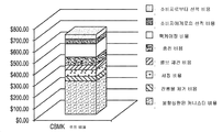
유체 고갈된 용기를 공급자에게 돌려보내는 것을 포함하는 이러한 주기는, 도 2b의 차트에 의해 반영되어 있는 바와 같이, 고가의 정비, 세정 및 성분 교체를 초래하며, 이때 도 2a의 공정 루프와 관련된 비용은, 도 2b에 도시된 3차원 컬럼의 상부에서부터 바닥으로 차례로, 소비자로부터의 선적 비용, 소비자에게로의 선적비용, 팩케이징 비용, 충전 비용, 밸브 재형성 비용, 세정 비용, 잔류 화학물질 제거 비용, 및 분할상환된 캐니스터 비용을 비롯한 비용 성분으로 내역이 밝혀져 있다. 도 2a에 도시된 공급 루프에서 전체 주기를 형성하는 1개 정격압력의 스테인레스강 캐니스터의 추정 비용은 약 $700이며, 상기 캐니스터를 갖지 않는 루프의 추정 비용 성분은 약 $325이다. This cycle, which includes returning the fluid-depleted vessel to the supplier, results in expensive maintenance, cleaning and component replacement, as reflected by the chart of Figure 2b, where the costs associated with the process loop of Figure 2a , The cost of shipping from a consumer, the cost of shipping to a consumer, the cost of packing, the cost of filling, the cost of rebuilding a valve, the cost of cleaning, the cost of removing residual chemicals, And cost components, including the cost of canned cancellation. The estimated cost of a single rated pressure stainless steel canister forming the entire cycle in the feed loop shown in FIG. 2A is about $ 700, and the estimated cost component of the loop without the canister is about $ 325.
이들 다양한 비용 및 반도체 산업에서 유체 공급 작업을 위한 스테인레스강 사용의 결점에도 불구하고, 정격압력의 스테인레스강 용기는, 이들의 정격압력 및 청정 규정으로 인하여, 반도체 제조 작업에 사용하기 위해 전형적으로 선택되고 있다. Despite these various costs and drawbacks of using stainless steels for fluid supply operations in the semiconductor industry, stainless steel vessels of rated pressure are typically selected for use in semiconductor manufacturing operations due to their rated pressure and cleanliness specifications have.
반도체 제조 분야에서 실질적 개수의 유체 전달 시스템은 대용량 캐니스트 중의 딥 튜브를 통하여 유체를 공정 캐니스터로 전달하기 위한 압력차를 이용하며, 상기 공정 캐니스터는 일반적으로 유체의 중단없는 공급을 위해 일정한 압력에서 유지된다. 이러한 설계의 한가지 문제점은 액체를 공정 캐니스터로 효과적으로 전달하기 위하여 대용량 캐니스터에서의 압력을 공정 캐니스터 내의 압력을 위로 상회하게 증가시켜야한다는 요건이다. 그와 같이, 이들 시스템은 일반적으로 대용량 캐니스터가 제조 비용이 소요(예컨대, 대략 $2,000 - $5,000의 제조 비용을 포함)될 뿐만 아니라 사용 및 수송에도 비용이 드는 정격압력의 스테인레스강 용기일 것을 필요로 하고, 또한 상기 스테인레스강 물질 작성은 반도체 제조 작업에 흔히 사용되는 다양한 유체와 반응성일 수 있다. A substantial number of fluid delivery systems in the field of semiconductor manufacturing utilize pressure differentials to deliver fluids to the process canister through dip tubes in high capacity cannisters which are typically maintained at a constant pressure for uninterrupted supply of fluid do. One problem with this design is the requirement that the pressure in the large canister be increased above the pressure in the process canister to effectively transfer the liquid to the process canister. As such, these systems generally require that large capacity canisters be stainless steel vessels of rated pressure that are not only costly to manufacture (including, for example, a manufacturing cost of approximately $ 2,000 to $ 5,000), but also expensive to use and transport , And the preparation of the stainless steel material may be reactive with various fluids commonly used in semiconductor manufacturing operations.
공정 캐니스터 내에서 30 psi(206.84 kPa)와 같은 표준 압력 수준이 반도체 제조 작업에서 유체의 전달을 위해 흔히 적용되지만, 특정 적용분야에서 상기 압력은 공급 용기와 반도체 공정 도구 사이의 거리, 및 반도체 공정 도구에서의 유체 압력 요건에 따라서 더 높을 수 있다. 대용량 캐니스터는 전형적으로 유체가 가압된 공정 캐니스터로 효과적으로 전달되게 하기 위하여 공정 캐니스터에 비하여 적어도 5 psi(34.5 kPa) 더 높아야 한다. 이러한 압력은 단일 중앙 대용량 전달 시스템으로부터 화학물질을 공급하는 팹-와이드(fab-wide) 분포 시스템에서 증가된다. While standard pressure levels, such as 30 psi (206.84 kPa) in the process canister, are commonly applied for the delivery of fluids in semiconductor manufacturing operations, the pressure in certain applications is dependent on the distance between the supply vessel and the semiconductor processing tool, Lt; / RTI > may be higher, depending on the fluid pressure requirements at. The large capacity canister typically must be at least 5 psi (34.5 kPa) higher than the process canister to allow fluid to be efficiently delivered to the pressurized process canister. This pressure is increased in a fab-wide distribution system that supplies chemicals from a single, central, high capacity delivery system.
그러나, 대용량 캐니스터(및 상기 공정 시스템의 다른 캐니스터) 중의 고압 가스는 시간이 경과함에 따라서 분배된 유체에서 가스 용해를 초래할 것이다(즉, 가스 연행이 일어날 것이다). 이러한 일은 상기 연행된 가스를 제거하기 위하여 유체 전달 시스템으로부터 탈가스제 다운스트림(degasser downstream)의 제공을 필요로 한다. 그러나, 탈가스제는 언제나 100% 효과적인 것은 아니다. 또한, 대다수의 유체가 캐니스터로부터 분배되므로, 잔류하는 유체는 더 많은 농도의 연행 가스를 함유하는 경향이 있고, 그 결과 잔류하는 유체는 통상 폐기된다. 이러한 폐기된 부피는 용기 내의 원래 유체 장입량의 10% 이상 정도로 많을 수 있다. 대부분의 반도체가 아주 고가인 것을 고려하면, 유체의 낭비는 문제가 된다.However, the high pressure gas in the large capacity canister (and other canisters of the process system) will cause gas dissolution in the dispensed fluid over time (i.e., gas entrainment will occur). This task requires the provision of a degasser downstream from the fluid delivery system to remove the entrained gas. However, degassing agents are not always 100% effective. Also, since the majority of the fluid is dispensed from the canister, the remaining fluid tends to contain a greater concentration of entrained gas, and the resultant fluid is typically discarded. This discarded volume may be as much as 10% or more of the original fluid loading in the vessel. Considering that most semiconductors are very expensive, waste of fluid is a problem.
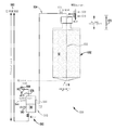
도 3은 서로에 대해 유체 유동 관계로 내부접속되어 있고, 각각 관련 가압 및 분배 라인을 갖는 대용량 캐니스터(301) 및 공정 캐니스터(302)를 포함하며, 유체가 상기 접속 라인을 통하여 대용량 캐니스터(301)로부터 공정 캐니스터(302)로 화살표(305)로 표시된 방향으로 흐르도록 배열되어 있는, 통상의 유체 전달 시스템(300)을 도시한다. 통상의 시스템에서, 상기 대용량 캐니스터(301)는 공정 캐니스터(302)의 압력보다 더 높은 압력 수준으로 가압된다. 상기 공정 캐니스터(302)는 유체를 사용 위치(예컨대, 반도체 제조 도구, 도 3에 도시되지 않음)까지 공급하도록 배열된다. 각 대용량 및 공정 캐니스터에 대한 입구 유동 회로 각각은 가압 가스 라인 및 진공 라인을 포함한다. 상기 가압 가스 라인은 불활성 가스, 예컨대 헬륨, 아르곤, 질소 등과 같은 가압 가스의 공급원에 결합될 수 있다.3 includes a
도 3에 도시된 예시적 유형의 캐니스터에서, 캐니스터에 잔류하는 유체의 측정은 흔히 그러한 용기 중의 플로트 센서의 제공에 의해 수용된다. 그러나, 플로트 센서는 고가이고 또 실패의 역사가 있다.In the exemplary type of canister shown in FIG. 3, the measurement of fluid remaining in the canister is often accommodated by the provision of a float sensor in such a container. However, float sensors are expensive and have a history of failure.
따라서, 당업자들은 유체 전달 시스템 및 방법에서 개선을 계속 추구하고 있다. 특정 목적은 유체 전달 시스템의 단순화, 대용량 포장용기의 비용 감소, 및 가스 연행으로 인한 유체 손실의 제거 또는 감소를 포함한다. Thus, those skilled in the art continue to seek improvements in fluid delivery systems and methods. Particular objectives include simplification of fluid delivery systems, cost reduction of large-capacity packaging containers, and elimination or reduction of fluid losses due to gas entrainment.
본 발명은 유체 전달 시스템 및 방법에 관한 것이다. The present invention relates to a fluid delivery system and method.
일 요지로서, 본 발명은, 유체를 사용 위치에 전달하기 위한 공정 캐니스터; 및 상기 공정 캐니스터에 적어도 하나의 대용량 캐니스터(bulk canister)로부터 유체를 공급하기 위한 전달 용기(transfer vessel)를 포함하며, 상기 전달 용기는 (i) 적어도 하나의 대용량 캐니스터로부터 유체를 뽑아내어 전달 용기로 보내고 적어도 하나의 대용량 캐니스터에서의 진공 조건을 선택적으로 유지하도록 배열된 진공 공급원, 및 (ii) 유체를 상기 전달 용기로부터 압력 중개로 상기 공정 캐니스터에 전달하도록 배열된 가압 가스의 제1 공급원과 결합되어 있는, 유체의 진공 및 압력 주기에 적응된(adapted) 유체 공급 시스템에 관한 것이다. As a matter of principle, the present invention provides a process canister comprising: a process canister for delivering fluid to a use position; And a transfer vessel for supplying fluid to the process canister from at least one bulk canister, wherein the transfer vessel is configured to: (i) extract fluid from at least one of the large capacity canisters And (ii) a first source of pressurized gas arranged to deliver fluid from the delivery vessel to the process canister by way of a pressure mediator, the vacuum source being arranged to selectively deliver the fluid to the process canister and to selectively maintain vacuum conditions in the at least one high capacity canister To a fluid supply system adapted to a vacuum and pressure cycle of the fluid.
다른 요지로서, 본 발명은, 진공하에서 유체를 적어도 하나의 대용량 캐니스터로부터 뽑아내어 전달 용기로 보내는 단계; 상기 전달 용기를 가압하여 상기 유체를 공정 캐니스터로 분배시키는 단계; 및 상기 공정 캐니스터에 공기를 공급하여 유체를 사용 위치로 전달시키는 단계를 포함하고, 상기 공정 캐니스터에 공급된 가스는 상기 전달 용기에 공급된 가스에 비하여 더 낮은 압력에 존재하는, 유체를 사용하기 위해 유체를 전달하는 방법에 관한 것이다. In another aspect, the present invention provides a method comprising: withdrawing fluid from at least one high capacity canister under vacuum and delivering it to a delivery vessel; Pressurizing the delivery vessel to distribute the fluid to the process canister; And supplying air to the process canister to deliver fluid to a use position, wherein the gas supplied to the process canister is at a lower pressure than the gas supplied to the delivery vessel To a method of delivering fluid.
다른 요지로서, 본 발명은, 다운스트림 공정에 적어도 하나의 토트(tote)로부터 유체를 공급하기 위한 저장기(reservoir)를 포함하며, 상기 저장기는 (i) 유체를 적어도 하나의 토트로부터 3 psig 미만의 압력에서 압력 중개로 상기 저장기에 전달하도록 배열된 가압 가스의 제1 공급원; 및 (ii) 유체를 상기 저장기로부터 압력 중개로 다운스트림 공정에 전달하도록 배열된 가압 가스의 제2 공급원과 결합되어 있는, 유체를 압력 분배하기 위한 유체 공급 시스템에 관한 것이다. In another aspect, the present invention includes a reservoir for supplying fluid from at least one tote to a downstream process, said reservoir comprising (i) a fluid from less than 3 psig A first source of pressurized gas arranged to deliver to the reservoir by a pressure mediator at a pressure of at least < And (ii) a second source of pressurized gas arranged to deliver fluid from the reservoir to the downstream process by pressure mediation.
또 다른 요지로서, 본 발명은, 제1 압력에서 제1 압력 공급원으로부터 가스를 토트에 적용하는 것에 의해 유체를 적어도 하나의 토트로부터 저장기로 전달하는 단계, 제2 압력에서 제2 압력 공급원으로부터 가스를 저장기에 적용하는 것에 의해 유체를 상기 저장기로부터 다운스트림 공정에 전달하는 단계를 포함하며, 상기 토트에 적용된 가스는 상기 저장기에 적용된 가스에 비하여 더 낮은 압력에 존재하는, 유체를 사용하기 위해 유체를 전달하는 방법에 관한 것이다. As a further aspect, the present invention provides a method comprising: transferring fluid from at least one tote to a reservoir by applying gas to the tote from a first pressure source at a first pressure, transferring the gas from the second pressure source at a second pressure Wherein the gas applied to the tote is at a lower pressure than the gas applied to the reservoir, wherein the gas applied to the tote is at a lower pressure than the gas applied to the reservoir. To a user.
유체를 적어도 하나의 토트로부터 저장기에 전달하는 단계; 및 유체를 상기 저장기로부터 다운스트림 공정에 전달하는 단계를 포함하는, 유체를 사용하기 위해 유체를 전달하는 방법에 관한 것이다.Transferring the fluid from the at least one tote to the reservoir; And transferring the fluid from the reservoir to a downstream process.
본 발명의 다른 요지, 특징 및 실시양태는 상세한 설명 및 첨부한 특허청구범위로부터 더욱 명백해질 것이다. Other features, features, and embodiments of the present invention will become more apparent from the detailed description and the appended claims.
도 1은 본 발명의 일 실시양태에 따른 유체 전달 시스템의 투시도이다.
도 2a는 통상의 유체 공급 캐니스터의 처리 및 배치 생활주기에 수반된 플로우 차트이다.
도 2b는 사용중인 도 2a의 통상의 유체 공급 캐니스터를 유지하는 비용 내역을 확인하는 차트이다.
도 3은 반도체 유체 공급 작업에 이용된 통상의 유체 전달 시스템의 개략적 투시도이다.
도 4a는 본 발명의 일 실시양태에 따른 유체 공급 캐니스터에 대한 처리 및 배치 단계 생활주기의 플로우 차트이다.
도 4b는 사용중인 도 4a의 유체 공급 캐니스터를 유지하는 비용 내역을 확인하는 차트이다.
도 5는 본 발명의 다른 실시양태에 따른 유체 전달 시스템의 투시도이다. 1 is a perspective view of a fluid delivery system in accordance with an embodiment of the present invention.
Figure 2a is a flowchart accompanying the processing and placement life cycle of a conventional fluid supply canister.
Figure 2b is a chart identifying the cost history of maintaining the conventional fluid supply canister of Figure 2a in use.
3 is a schematic perspective view of a typical fluid delivery system used in a semiconductor fluid supply operation.
4A is a flow chart of a processing and deployment phase life cycle for a fluid supply canister in accordance with one embodiment of the present invention.
Figure 4b is a chart identifying the cost history of maintaining the fluid supply canister of Figure 4a in use.
5 is a perspective view of a fluid delivery system in accordance with another embodiment of the present invention.
본 발명은 대용량 캐니스터와 공정 캐니스터 사이에서 압력 버퍼로서 작용하는 전달 용기를 포함하는 유체 전달 시스템 및 방법에 관한 것이다. 일부 실시양태에서, 상기 대용량 캐니스터는 진공에 의해 상기 전달 용기에 전달되어, 높은 정격압력 스테인레스강 포장용기의 필요성을 없앤다. 상기 전달 용기에 전달된 내용물은 압력하에서 공정 캐니스터로 이동될 수 있다. 다른 실시양태에서, 대용량 캐니스터의 물질은 비교적 낮은 압력하의 중개 전달 용기(본 명세서에서는 "저장기"로도 부름)로 전달될 수 있다. 이 물질은 상기 저장기로부터 비교적 고압하의 다운스트림 공정(예컨대, 도구, 또는 공정 캐니스터)으로 전달될 수 있다. The present invention relates to a fluid delivery system and method that includes a delivery vessel that acts as a pressure buffer between a large capacity canister and a process canister. In some embodiments, the high capacity canister is transferred to the delivery vessel by vacuum, eliminating the need for a high rated pressure stainless steel packaging vessel. The contents delivered to the delivery vessel can be transferred to the process canister under pressure. In another embodiment, the material of the high capacity canister can be delivered to an intermediate delivery vessel (also referred to herein as a " reservoir ") at relatively low pressures. This material may be transferred from the reservoir to a downstream process (e.g., a tool, or process canister) at relatively high pressures.
일 실시양태에서, 상기 액체 전달 시스템은 중개 용기(본 명세서에서는 "전달 용기"로도 다양하게 지칭됨)를 이용하여 유체를 대용량 캐니스터(본 명세서에서는 "대용량 저장 용기" 또는 "토트"라고도 함)로부터 진공 및 압력 주기를 이용하는 공정 캐니스터로 전달하여 상응하는 유체 유동이 실시되게 한다. 일부 실시양태에서, 전달 용기와 결합된 진공은 대용량 저장 용기 가압을 필요로 하지 않고도 대용량 캐니스터(또는 적합하게 필요한 물질, 형상, 크기 등의 공급원 포장용기)로부터 유체를 뽑아내므로, 대용량 캐니스터가 정격압력 스테인레스강 캐니스터인 요건을 피하게 한다. 이것은 다시 대용량 캐니스터가 저비용의 비-정격압력 용기이도록 허용하여, 유체를 사용 위치까지 전달하는데 나쁜 영향을 주지 않고도도 유체를 가압 공정 캐니스터로 전달한다. 이러한 비-정격압력 용기 또는 캐니스터로부터 액체를 공급하는 능력은 특정 포장용기가 유체 및/또는 수송 요건을 기초로 선택되게 하며, 스테인레스강이 최적 선택이 아닌 적용분야에서 분명하고 비용 효과적인 이점을 제공한다. 다양한 실시양태에서, 다른 포장용기는, 비제한적으로, 강성, 반-강성, 접이식, 및/또는 접을 수 있는, 예를 들어, 플라스틱 용기, 유리병, 및 접이식 라이너, 예를 들어 오버팩 내에 배치된 라이너를 포함할 수 있는 "박스 중의 백" 또는 "병 중의 백" 포장용기일 수 있는 단독형(stand-alone) 포장용기를 포함하도록 제공되어 있다. 본 명세서에 사용된 바와 같이, 상기 용어 "캐니스터" 및 "용기"는 일반적으로 유체를 지지할 수 있는 포장용기, 팩케이지, 및/또는 밀폐가능한 인클로져(enclosure)를 지칭한다. 따라서, "캐니스터" 또는 "용기"는 일부 실시양태에서 라이너 및/또는 오버팩을 포함할 수 있다. In one embodiment, the liquid delivery system is configured to dispense fluids from a large capacity canister (also referred to herein as a " bulk storage container "or" tote ") using an intermediate vessel To a process canister using a vacuum and pressure cycle to cause a corresponding fluid flow to be effected. In some embodiments, the vacuum associated with the delivery vessel draws fluid from a large capacity canister (or suitably the source packaging vessel, such as the required material, shape, size, etc.) without requiring mass storage vessel pressurization, Avoid requirements that are pressure stainless steel canisters. This again allows the large capacity canister to be a low cost, non-rated pressure vessel, delivering the fluid to the pressurization process canister without adversely affecting delivery of the fluid to the use position. The ability to supply liquid from such non-rated pressure vessels or canisters allows a particular packaging vessel to be selected based on fluid and / or transport requirements, and provides a clear and cost effective advantage in applications where stainless steel is not the optimal choice . In various embodiments, the other packaging containers may include, but are not limited to, rigid, semi-rigid, foldable, and / or collapsible, e.g., plastic containers, glass bottles, and collapsible liners, Quot; bag in a box " or "bag in a bottle " packaged container that may include a liner that has been wrapped around the liner. As used herein, the terms "canister" and "container" refer generally to a packaging container, a packaged cage, and / or a sealable enclosure capable of supporting a fluid. Thus, a "canister" or "container" may include a liner and / or an overpack in some embodiments.
대용량 캐니스터, 전달 용기, 및/또는 공정 캐니스터를 비롯한 본 명세서에 기재된 임의 포장용기에 대한 본 발명의 실시양태에 따라 사용될 수 있는 라이너 및/또는 오버팩 유형의 다른 예는 국제 PCT 출원 번호 PCT/US2012/070866호, 발명의 명칭 "라이너 기반 선적 및 분배 시스템", 2012년 12월 20일 출원; 국제 PCT 출원 번호 PCT/US11/55558호, 발명의 명칭 "유리병을 치환하기 위한 실질적으로 강성 접이식 라이너, 용기 및/또는 라이너, 및 향상된 신축성 라이너", 2011년 10월 10일 출원; 국제 PCT 출원 번호 PCT/US11/55560호, 발명의 명칭 "네스티드(nested) 블로우 성형된 라이너 및 오버팩 및 그의 제조 방법", 2011년 10월 10일 출원; 미국 가출원 번호 61/468,832, 발명의 명칭 "라이너 기반 분배기", 2011년 3월 29일 출원; 미국 가출원 번호 61/525,540, 발명의 명칭 "라이너 기반 분배 시스템", 2011년 8월 19일 출원; 미국 특허 출원 번호 11/915,996, 발명의 명칭 "유체 저장 및 분배 시스템 및 공정", 2006년 6월 5일 출원; 국제 PCT 출원 번호 PCT/US 10/51786, 발명의 명칭 "물질 저장 및 분배 시스템 및 탈기 어셈블리를 사용한 방법", 2010년 10월 7일 출원, 국제 PCT 출원 번호 PCT/US10/41629호, 미국 특허 번호 7,335,721호, 미국 특허 출원 번호 11/912,629호, 미국 특허 출원 번호 12/302,287호, 및 국제 PCT 출원 번호 PCT/US08/85264호에 더욱 자세하게 기재되어 있고, 이들 각각은 그 전체가 참조에 의해 본 명세서에 포함된다. Other examples of liner and / or overpack types that may be used in accordance with embodiments of the present invention for any packaging container described herein, including large capacity canisters, delivery containers, and / or process canisters, are described in International PCT Application No. PCT / US2012 / 070866, entitled " Liner Based Shipping and Distribution System ", filed December 20, 2012; International PCT Application No. PCT / US11 / 55558 entitled " Substantially rigid foldable liner, container and / or liner for replacing glass bottles, and improved stretch liner "filed October 10, 2011; International PCT Application No. PCT / US11 / 55560, entitled " Nested Blow Molded Liner and Overpack and Method of Making It, "filed October 10, 2011; U.S. Provisional Application No. 61 / 468,832 entitled "Liner Based Dispenser", filed March 29, 2011; U.S. Provisional Application No. 61 / 525,540 entitled "Liner Based Distribution System", filed on August 19, 2011; U. S. Patent Application Serial No. 11 / 915,996 entitled " Fluid Storage and Distribution System and Process ", filed June 5, 2006; International PCT Application No. PCT / US 10/51786, entitled " METHOD FOR USING MATERIAL STORAGE AND DISTRIBUTION SYSTEM AND DEPOSITION ASSEMBLY, " filed October 7, 2010, International PCT Application No. PCT / US10 / 41629, No. 11 / 912,629, U.S. Patent Application No. 12 / 302,287, and International PCT Application No. PCT / US08 / 85264, each of which is incorporated herein by reference in its entirety, .
일부 실시양태에서, 본 발명에 따라 사용된 하나 이상의 포장용기는 튜브 형상의 본체부, 체결부(fitment)를 포함하는 상부, 및 물질을 지지하기 위해 둘러싸인 내부를 정의하는 저부를 포함하는 라이너를 일반적으로 포함하며, 이들의 예는 더욱 자세하게는 국제 PCT 출원 번호 PCT/US2011/064141호, 발명의 명칭 "압력 분배 시스템에 사용하기 위한 일반적으로 실린더 형상의 라이너 및 그의 제조 방법", 2011년 12월 9일 출원에 기재되어 있으며, 이들 전체 내용은 본 명세서에 포함되어 있다. In some embodiments, the at least one packaging container used in accordance with the present invention comprises a liner comprising a tubular body portion, an upper portion including a fitment, and a bottom defining an interior enclosed to support the material, , Examples of which are described in more detail in International PCT Application No. PCT / US2011 / 064141, entitled " a generally cylindrical liner for use in a pressure distribution system and method for its manufacture ", December 9, 2011 , The entire contents of which are incorporated herein by reference.
또한 본 발명의 특정 실시양태에 따라 사용될 수 있는 라이너 및/또는 오버팩은 접선(fold line) 또는 접이식 패턴을 규정하는 접음 패턴(fold pattern)을 포함할 수 있는 실질적으로 강성 접이식 포장용기 및 신축성(flexible) 포장용기를 포함한다. 일부 실시양태에서, 일부의 이러한 포장용기는 저장 및 분배 시스템에 적합할 수 있는 접선을 갖는 블로우 성형된, 실질적으로 강성의 접이식 포장용기일 수 있고 또 실질적으로 약 1 리터 이하 내지 약 200 리터 이상의 크기일 수 있다. 상기 실질적으로 강성의 접이식 포장용기는 예컨대 외부 포장용기 없이 사용되는 단독형 포장용기일 수 있고, 또 펌프 또는 가압 유체, 또는 그의 조합을 사용하는 것을 포함하는 적합한 수단에 의해 분배될 수 있다. 일부 실시양태에서, 상기 포장용기 벽은 폴리에틸렌 테레프탈레이트(PET), 폴리에틸렌 나프탈레이트(PEN), 폴리(부틸렌 2,6-나프탈레이트)(PBN), 폴리에틸렌(PE), 선형 저밀도 폴리에틸렌(LLDPE), 저밀도 폴리에틸렌(LDPE), 중밀도 폴리에틸렌(MDPE), 고밀도 폴리에틸렌(HDPE), 및 폴리프로필렌(PP)의 적어도 하나를 사용하여 제조될 수 있다. 일부 실시양태에서, 상기 포장용기의 2개의 대향하는 측벽은 상기 포장용기를 접을 때 대향 측벽으로 하여금 주름지게하는 소정의 접선을 포함할 수 있다. 이 일반 유형의 포장용기의 더욱 상세한 설명은 국제 PCT 출원 번호 PCT/US2012/051843호, 발명의 명칭 "접음 패턴을 갖는 실질적으로 강성 접이식 용기", 2012년 8월 22일 출원; 및 미국 가특허 출원 번호 61/729,766호, 발명의 명칭 "실질적으로 강성 접을 수 있는 용기", 2012년 11월 26일 출원에 기재되어 있고, 이들은 전체가 본 명세서에 포함되어 있다. Also, the liner and / or overpack that may be used in accordance with certain embodiments of the present invention may include a substantially rigid foldable packaging container that may include a fold line or a fold pattern that defines a foldable pattern, flexible packaging containers. In some embodiments, some such packaging containers may be blow molded, substantially rigid, foldable packaging containers having a tangent line that may be suitable for storage and dispensing systems, and may have a size substantially less than about 1 liter to about 200 liters . The substantially rigid foldable packaging container may be a stand-alone packaging container used, for example, without an outer packaging container, and may be dispensed by any suitable means, including using a pump or pressurized fluid, or a combination thereof. In some embodiments, the packaging container wall is formed from a material selected from the group consisting of polyethylene terephthalate (PET), polyethylene naphthalate (PEN), poly (butylene 2,6-naphthalate) (PBN), polyethylene (PE), linear low density polyethylene (LLDPE) , Low density polyethylene (LDPE), medium density polyethylene (MDPE), high density polyethylene (HDPE), and polypropylene (PP). In some embodiments, two opposing sidewalls of the packaging container may include a predetermined tangent to cause the opposing sidewalls to wrinkle when folding the packaging container. A more detailed description of this general type of packaging can be found in International PCT Application No. PCT / US2012 / 051843 entitled " substantially rigid foldable container with a folding pattern "filed on August 22, 2012; And U. S. Patent Application No. 61 / 729,766, entitled " Substantially Rigid Foldable Container, "filed November 26, 2012, which are incorporated herein by reference in their entirety.
라이너 및/또는 오버팩을 포함할 수 있는 본 발명의 캐니스터 및 용기의 실시양태는 ATMI, 인코포레이티드에 의해 상품명 NOWpak®으로 시판되는 초크-오프(choke-off) 및 라이너를 제한하거나 제거하는 방법을 포함하는 접선 및/또는 라이너를 함유하는 비제한적으로, 신축성, 강성 접이식, 2-차원, 3-차원, 용접되고, 성형된, 주름진, 및/또는 비-주름 라이너, 및/또는 라이너를 포함한 상기 언급된 출원에 개시된 실시양태, 형태 및/또는 향상을 포함할 수 있다. 또한, 본 명세서에 기재된 실시양태에 개시된 분배 시스템의 다양한 특징은 다른 실시양태에 관하여 기재된 하나 이상의 특징과 조합되어 사용될 수 있다. Embodiments of the canisters and containers of the present invention, which may include liner and / or overpacks, include choke-offs marketed under the trade name NOWpak® by ATMI, Rigid folded, two-dimensional, three-dimensional, welded, molded, wrinkled, and / or non-wrinkled liner and / or liner containing tangential lines and / And / or improvements disclosed in the above-mentioned applications including, but not limited to, In addition, various features of the dispensing system disclosed in the embodiments described herein may be used in combination with one or more features described with respect to other embodiments.
다양한 본 발명의 실시양태가 반도체 산업에 사용하기 위한 물질을 함유하는 것으로 기재되어 있지만, 적합한 물질을 저장 및/또는 분배하기 위해 본 발명의 실시양태가 사용될 수 있는 것으로 이해될 것이다. 본 발명의 실시양태를 이용하여 저장되고, 선적되며, 및/또는 분배될 수 있는 임의 유형의 물질의 예는, 비제한적으로, 초순도 액체, 예컨대 산, 용매, 염기, 포토레지스트, 슬러리, 세제, 세정 배합물, 도펀트, 무기, 유기, 금속유기, TEOS, 및 생물학적 용액, DNA 및 RNA 용매 및 시약, 약제, 인쇄가능한 전자제품 무기 및 유기 물질, 리튬 이온 또는 기타 전지 유형전해액, 나노물질(예를 들어, 풀러렌, 무기 나노입자, 졸-겔, 및 기타 세라믹 포함), 및 방사능 화학물질; 살충제/비료; 페인트/광택제/용매/코팅-물질 등; 접착제; 파워 세척 유체; 예컨대 자동차 또는 항공기 산업에서 사용하기 위한 윤활제; 비제한적으로, 예를 들어 양념, 조리용 오일, 및 소프트 음료와 같은 식품 제품; 생물의학 또는 연구 산업에 사용하기 위한 시약 또는 기타 물질; 예를 들어 군대에 이해 사용되는 유해 물질; 폴리우레탄; 농약; 공업 화학물질; 화장품 화학물질; 석유 및 윤활제; 실란트; 건강 및 경구 위생 제품 및 화장실용 제품; 또는 예를 들어 압력 분배에 의해 분배될 수 있는 기타 물질을 포함한다. 본 발명의 실시양태와 함께 사용될 수 있는 물질은 고점도 및 저점도 유체를 포함한 임의 점도를 가질 수 있다. 당업자들은 개시된 실시양태의 이점을 잘 인식할 것이므로, 다양한 산업 및 다양한 제품의 수송 및 수송을 위해 개시딘 실시양태의 적합성을 인식할 것이다. 일부 실시양태에서, 상기 저장, 선적, 및 분배 시스템은 반도체, 플랫 패널 디스플레이, LED, 및 태양 패널의 제조와 관련된 산업; 접착제 및 폴리아미드의 적용을 포함한 산업; 포토리소그래피 기술을 이용하는 산업; 또는 다른 중요 물질 전달 적용에서 특히 유용할 수 있다. 예를 들어, 이러한 본 발명의 포장용기의 이용은, 비제한적으로, 초고순도 화학물질 및/또는 예를 들어 마이크로전자 제조, 반도체 제조, 및 플랫 패널 디스플레이 제조와 같은 산업에 사용하기 위한 포토레지스트, 범프 레지스트 세정 용매, TARC/BARC(상면 항반사성 코팅/저면 항반사성 코팅), 저분자량 케톤 및/또는 구리 화학물질과 같은 물질을 수송 및 분배하는 것을 포함한다. 부가적 용도는, 비제한적으로, 산, 용매, 염기, 슬러리, 세정 배합물, 도펀트, 무기, 유기, 금속유기, TEOS, 및 생물학적 용액, 약제, 및 방사능 화학물질을 수송 및 분배하는 것을 포함할 수 있다. 그러나, 이러한 포장용기는 다른 산업에서도 또 비제한적으로, 페인트, 소프트 음료, 조리용 오일, 농약, 건강 및 경구 위생 제품, 및 화장실 제품 등과 같은 다른 제품을 수송 및 분배하기 위해 사용될 수 있다. 당업자들은 이러한 포장용기 및 그를 사용하고 제조하는 방법의 이점을 잘 인식할 것이므로, 다양한 산업에 사용하고 또 다양한 제품의 분배방법에 대한 라이너의 적합성을 인식할 것이다. While various embodiments of the present invention are described as containing materials for use in the semiconductor industry, it will be appreciated that embodiments of the present invention may be used to store and / or dispense suitable materials. Examples of any type of material that can be stored, shipped, and / or dispensed using embodiments of the present invention include, but are not limited to, ultra pure liquids such as acids, solvents, bases, photoresists, , Cleaning compounds, dopants, inorganic, organic, metal organic, TEOS, and biological solutions, DNA and RNA solvents and reagents, pharmaceuticals, printable electronics inorganic and organic materials, lithium ion or other cell type electrolytes, Including fullerenes, inorganic nanoparticles, sol-gels, and other ceramics), and radioactive chemicals; Pesticides / fertilizers; Paint / polish / solvent / coating-material etc; glue; Power cleaning fluid; Lubricants for use in, for example, the automotive or aircraft industry; But are not limited to, food products such as, for example, spices, cooking oils, and soft drinks; Reagents or other substances for use in the biomedical or research industry; For example, harmful substances used in the military; Polyurethane; pesticide; Industrial chemicals; Cosmetic chemicals; Petroleum and lubricants; Sealant; Health and oral hygiene products and toilet products; Or other materials that can be dispensed, for example by pressure distribution. Materials that may be used with embodiments of the present invention may have any viscosity, including high viscosity and low viscosity fluids. Those skilled in the art will recognize the benefits of the disclosed embodiments and will therefore appreciate the suitability of the disclosure embodiments for the transport and transport of various industries and diverse products. In some embodiments, the storage, shipping, and dispensing systems are related to the manufacture of semiconductors, flat panel displays, LEDs, and solar panels; Industries including the application of adhesives and polyamides; Industries using photolithography techniques; Or other critical mass transfer applications. For example, the use of such a packaging container of the present invention can be used in a variety of applications including, but not limited to, photoresists for use in industries such as ultra high purity chemicals and / or industries such as microelectronic manufacturing, semiconductor manufacturing, and flat panel display manufacturing, Bump resist cleaning solvents, TARC / BARC (top anti-reflective coating / bottom anti-reflective coating), low molecular weight ketone and / or copper chemicals. Additional applications may include, but are not limited to, transporting and dispensing acids, solvents, bases, slurries, cleaning formulations, dopants, inorganic, organic, metal organic, TEOS, and biological solutions, have. However, such packaging containers may be used in other industries and also for transporting and dispensing other products such as, but not limited to, paints, soft drinks, cooking oils, pesticides, health and oral hygiene products, Those skilled in the art will recognize the suitability of the liner for use in a variety of industries and for dispensing methods of various products, as those skilled in the art will appreciate the advantages of such packaging containers and methods of using and manufacturing them.
본 발명의 포장용기, 용기, 오버팩 및/또는 라이너는 적합한 물질 또는 물질의 조합, 예를 들어 비제한적으로, 금속 물질, 또는 플라스틱, 나일론, EVOH, 폴리에스테르, 폴리올레핀, 또는 다른 천연 또는 합성 중합체를 비롯한 하나 이상의 중합체로 이루어질 수 있다. 다른 실시양태에서, 상기 포장용기는 폴리에틸렌 테레프탈레이트(PET), 폴리에틸렌 나프탈레이트(PEN), 폴리(부틸렌 2,6-나프탈레이트)(PBN), 폴리에틸렌(PE), 선형 저밀도 폴리에틸렌(LLDPE), 저밀도 폴리에틸렌(LDPE), 중밀도 폴리에틸렌(MDPE), 고밀도 폴리에틸렌(HDPE), 폴리프로필렌(PP), 및/또는 비제한적으로, 폴리클로로트리플루오로에틸렌(PCTFE), 폴리테트라플루오로에틸렌(PTFE), 플루오르화된 에틸렌 프로필렌(FEP), 및 퍼플루오로알콕시(PFA)와 같은 플루오로중합체를 사용하여 제조될 수 있다. 상기 포장용기는 비제한적으로, 병, 깡통, 드럼 등과 같은 적합한 형상 또는 형태일 수 있다. The packaging container, container, overpack and / or liner of the present invention can be made from any suitable material or combination of materials, such as, but not limited to, a metal material or a plastic, nylon, EVOH, polyester, polyolefin, , ≪ / RTI > and the like. In another embodiment, the packaging container may be made of polyethylene terephthalate (PET), polyethylene naphthalate (PEN), poly (butylene 2,6-naphthalate) (PBN), polyethylene (PE), linear low density polyethylene (LLDPE) (PCTFE), polytetrafluoroethylene (PTFE), polytetrafluoroethylene (PTFE), polypropylene (PP), and / or polybutylene terephthalate , Fluorinated ethylene propylene (FEP), and perfluoroalkoxy (PFA). The packaging container can be of any suitable shape or shape, such as, but not limited to, bottles, cans, drums, and the like.
본 발명의 상기 유체 공급 시스템은, 기존의 전달 시스템의 효율 및 비용 효율을 억제하였던 엄격한 호환성(compatibility) 요건의 억제 없이, 수송 및 화학적 요건을 기초로 하여 유체의 팩케이징을 가능하게 한다. 또한, 앞서 언급한 바와 같이, 통상의 유체 공급 캐니스터는 재생 및 재충전을 위해 공급자에게 반환되는 것을 비롯한 생활주기 관리 공정을 필요로 한다. 본 발명의 방법은 재생가능한 및/또는 일회용 물질로 제조된 캐니스터의 적용을 가능하게 함으로써, 이러한 용기가 공급자에게 반환될 필요성을 제거한다. 이는 다시 도 2a에 도시된 통상의 생활 관리 주기를 파기하고 또 이러한 사용/반환/재생/재충전/전달 주기가 도 4a에 도시된 바와 같은 유형의 원-웨이(one-way) 캐니스터 공급 설계로 교체되게 한다. 캐니스터 생활주기 관리 공정에서의 이러한 변화는 도 4b의 비용 내역 차트에 의해 도시되는 바와 같이 상당한 절약을 달성할 수 있다.The fluid supply system of the present invention enables fluid packing on the basis of transport and chemical requirements, without compromising the stringent compatibility requirements that have inhibited the efficiency and cost effectiveness of existing delivery systems. Also, as noted above, conventional fluid supply canisters require a life cycle management process, including returning to the supplier for regeneration and refill. The method of the present invention enables the application of a canister made of a renewable and / or disposable material, thereby eliminating the need for such a container to be returned to the supplier. This again destroys the normal life management cycle shown in FIG. 2A, and the use / return / regeneration / refill / delivery cycle is replaced with a one-way canister supply design of the type shown in FIG. 4A . This change in the canister life cycle management process can achieve significant savings as shown by the cost history chart of Figure 4B.
다양한 실시양태에서, 상기 전달 용기는 대용량 캐니스터 및 공정 캐니스터의 크기(부피용량)에 비하여 크기가 작다. 이러한 크기의 차이는, 공정 캐니스터의 재충전이 필요할 때까지 상기 전달 용기가 진공 상태로 유지되게 한다. 이것은 다시 유체 중에 용해된 가스를 최소화한다. 다양한 실시양태에서의 상기 전달 용기는 표준 압력 캐니스터에 접속됨으로써 하위 호환성(backward compatibility)을 유지한다. 다양한 실시양태에서, 본 명세서에 개시된 시스템은 소망하는 캐니스터 시스템에 적응될 수 있고, 또 유체를 지지할 수 있는 포장용기, 팩케이지, 리셉터클(receptacle) 또는 인클로져와 호환가능하다. In various embodiments, the delivery vessel is small in size relative to the size (volume capacity) of the large capacity canister and the process canister. This difference in size allows the delivery vessel to remain in a vacuum until recharging of the process canister is required. This again minimizes the gas dissolved in the fluid. The delivery container in various embodiments maintains backward compatibility by being connected to a standard pressure canister. In various embodiments, the systems described herein are compatible with a packaging container, pack cage, receptacle, or enclosure that can be adapted to a desired canister system and can also support fluid.
다양한 실시양태에서, 본 발명의 상기 시스템 및 방법은 비어있음 검출("종점 검출기")을 위해 이용되는 값비싸고 실패하기 쉬운 액체 레벨 센서(예컨대 플로트 센서)의 필요성을 제거한다. 일 실시양태에서, 상기 플로트 센서는 캐니스터의 비어 있는 상태를 결정하기 위해 이용된 압력 변화 대 시간 알고리즘 방법에 의해 제거될 수 있다. 일 실시양태에서, 압력 변환기는 대용량 캐니스터 내의 유체의 압력을 감지하여서 이러한 압력을 나타내는 변환기 출력을 즉각적으로 생성한다. 이러한 변환기 출력을 수용하고 또 유체의 압력 변화율을 결정하도록 처리기(processor)를 적응시켜 대용량 캐니스터에서 유체 소비 개시와 관련있는 변화율 증가를 나타내는 처리기 출력을 제공한다. 시스템 및 방법을 모니터링하는 이러한 압력 변환기는 비제한적으로, 대용량 캐니스터, 전달 용기, 및 공정 캐니스터를 비롯한 유체 공급 시스템의 캐니스터 또는 용기 상에서 이용될 수 있다. In various embodiments, the system and method of the present invention eliminates the need for a costly and liable liquid level sensor (e.g., a float sensor) that is used for empty detection ("endpoint detector"). In one embodiment, the float sensor can be removed by a pressure change versus time algorithm method used to determine the empty state of the canister. In one embodiment, the pressure transducer senses the pressure of the fluid in the large capacity canister and immediately produces a transducer output representative of this pressure. The processor is adapted to receive the transducer output and to determine the rate of pressure change of the fluid to provide a processor output indicative of a rate of change increase associated with fluid consumption initiation in the large capacity canister. These pressure transducers for monitoring systems and methods can be used on a canister or vessel of fluid supply systems including, but not limited to, large capacity canisters, delivery vessels, and process canisters.
다른 실시양태에서, 적합한 레벨 모니터링 방법을 이용하여 본 발명의 캐니스터와 함께 이용할 수 있다. 예를 들어, 포장용기로부터 유체의 분배를 제어하고 포장용기가 비워지는 것에 가까와 질 때를 결정하는 수단은 각기 참조에 의해 전체가 본 명세서에 포함된 미국 특허 번호 7,172,096호, 발명의 명칭 "액체 분배 시스템", 2007년 2월 6일 발행 및 PCT 출원 번호 PCT/US07/70911호, 발명의 명칭 "가스 제거를 포함한 액체 분배 시스템", 2007년 6월 1일 국제출원일 및 전체가 참조에 의해 본 명세서에 포함된 국제 특허 출원 번호 PCT/US2011/055558호에 기재되어 있다. 이와 관련하여, 일부 실시양태에서, 분배기는 적합한 레벨 감지 특징 또는 센서를 포함할 수 있다. 이러한 레벨 감지 특징 또는 센서는 분배기에 저장된 내용물의 레벨을 확인하고, 표시하거나, 또는 결정하기 위한 시각적, 전자적, 초음파 또는 기타 적합한 메카니즘을 이용할 수 있다.In other embodiments, suitable level monitoring methods can be used with the canister of the present invention. For example, the means for controlling dispensing of a fluid from a packaging container and determining when the packaging container is about to emptying is disclosed in U. S. Patent No. 7,172, 096, entitled "Liquid Distribution System ", issued February 6, 2007 and PCT Application No. PCT / US07 / 70911, entitled" Liquid Distribution System Including Gas Removal ", filed on June 1, 2007, International Patent Application No. PCT / US2011 / 055558, which is incorporated herein by reference. In this regard, in some embodiments, the dispenser may include suitable level sensing features or sensors. These level sensing features or sensors may utilize visual, electronic, ultrasonic or other suitable mechanisms for identifying, displaying, or determining the level of content stored in the dispenser.
다른 실시양태에서, 유량 측정 기술은 제1 캐니스터로부터 전달용기로 및/또는 상기 전달 용기로부터 다운스트림 캐니스터 또는 공정으로 전달되는 물질을 직접적으로 측정하는 수단과 통합되거나 또는 기능적으로 결합될 수 있다. 전달될 물질의 직접적 측정은 최종 사용자에게 공정 반복성 또는 재현성을 도울 수 있는 데이터를 제공할 수 있다. 일 실시양태에서, 상기 유량계는 물질 유동의 아날로그 또는 디지털 판독을 제공할 수 있다. 상기 시스템의 상기 유량계, 또는 다른 부품은 물질의 특징(비제한적으로 점도 및 농도 포함) 및 기타 유동 변수를 고려하여 정확한 유동 측정을 제공할 수 있다. 부가적으로, 또는 다르게는, 상기 유량계는 분배기에 저장되고 분배되는 특정 물질과 함께 작동하고, 또 완전히 그를 측정하도록 구성될 수 있다. 일 실시양태에서, 상기 유입 압력은 실질적으로 일정한 출구 압력 또는 유속을 유지하도록 순환되거나 또는 조정될 수 있다. In another embodiment, the flow measurement technique may be integrated or functionally combined with a means for directly measuring the substance transferred from the first canister to the delivery vessel and / or from the delivery vessel to the downstream canister or process. Direct measurement of the material to be delivered can provide data to the end user that can aid in process repeatability or reproducibility. In one embodiment, the flow meter can provide an analog or digital reading of the material flow. The flow meter, or other part of the system, can provide accurate flow measurements, taking into account the characteristics of the material (including, but not limited to, viscosity and concentration) and other flow parameters. Additionally or alternatively, the flow meter may be configured to operate with and completely measure the specific material stored and dispensed in the dispenser. In one embodiment, the inflow pressure can be cycled or adjusted to maintain a substantially constant outlet pressure or flow rate.
다양한 실시양태에서, 전달 용기와 종점 모니터링 방법의 조합은 상기 시스템 내의 전체 유체 품목을, 상기 용기의 저부에 현저한 잔류량을 남기지 않고 실질적으로 이용되게할 것이다(이러한 잔류 유체는 보통 "힐"이라 칭한다). 따라서 상기 전달 용기 시스템은 액체에 존재하는 현저한 양의 연행 가스의 존재를 피하게 하며, 이는 전형적으로 통상의 고압 유체 공급 시스템의 동작에서 관찰된다. In various embodiments, a combination of a delivery vessel and an endpoint monitoring method will cause the entire fluid item in the system to be substantially utilized without leaving a significant residual amount in the bottom of the vessel (such residual fluid is commonly referred to as a "heel & . The delivery vessel system thus avoids the presence of a significant amount of entrained gas present in the liquid, which is typically observed in the operation of conventional high pressure fluid supply systems.
일 실시양태에서, 유체 공급 시스템은 유체의 진공 및 압력 주기에 맞게 적응되며 또 유체를 사용 위치(예컨대 반도체 공정 도구)에 전달하도록 적응된 공정 캐니스터, 및 상기 공정 캐니스터에 적어도 하나의 대용량 캐니스터로부터의 유체를 공급하도록 적응된 전달 용기를 포함하며, 상기 전달 용기는 (i) 적어도 하나의 대용량 캐니스터로부터 유체를 빼내어서 전달 용기로 보내어서 적어도 하나의 대용량 캐니스터에서 진공 상태를 선택적으로 유지하기 위한 진공 공급원, 및 (ii) 유체를 상기 전달 용기로부터 압력 중개로 공정 캐니스터로 전달하기 위한 가압 가스의 제1 공급원과 결합된다.In one embodiment, the fluid supply system includes a process canister adapted to suit the vacuum and pressure cycles of the fluid and adapted to deliver fluid to a location of use (e.g., a semiconductor processing tool), and a process canister adapted to receive fluid from the at least one high capacity canister (I) a vacuum source for selectively withdrawing fluid from at least one high capacity canister to a delivery vessel to maintain a vacuum state in at least one high capacity canister, the vacuum vessel comprising: And (ii) a first source of pressurized gas for delivering fluid from the delivery vessel to the process canister by pressure distribution.
본 발명의 시스템 및 방법의 동작에서, 공급될 유체에서 가스의 연행을 배제하기 위하여 진공이 선택적으로 유지된다. 다양한 실시양태에서, 상기 전달 용기는 진공상태와 압력상태 사이에서 순환될 것이다. 진공상태에서, 진공의 양은 (1) 대용량 캐니스터로부터 유체를 빼내거나, 또는 (2) 대용량 캐니스터 내에서 적어도 최소 진공을 유지하여 가스 연행 발생을 최소로 제어하도록 선택적으로 조절된다. 일 실시양태에서, 상기 진공상태는 선택적으로 종료될 수 있고(예컨대 상기 전달 용기와 대용량 포장용기를 접속하는 유체 유동 라인 내의 밸브를 닫는 것에 의해), 전달 용기에 적용되면 또는 적용 직후 압력은 유체를 용기로부터 공정 캐니스터로 위치되게한다. 다양한 본 발명의 실시양태에서, 공정 포장용기는 유체를 대용량 캐니스터로부터 전달 용기로 공급하는 것에 의해 비워지지 않은 상태에서 유지될 수 있어, 이러한 유체를 이용하는 공정은 연속적으로 흐를 수 있다.In operation of the system and method of the present invention, a vacuum is selectively maintained to exclude the entrainment of gas in the fluid to be fed. In various embodiments, the delivery vessel will be circulated between a vacuum state and a pressure state. In the vacuum state, the amount of vacuum is selectively adjusted to (1) draw fluid out of the large capacity canister, or (2) maintain at least a minimum vacuum in the large capacity canister to minimize the generation of gas entrainment. In one embodiment, the vacuum state can be selectively terminated (e.g., by closing the valve in the fluid flow line connecting the delivery vessel and the high-capacity packaging vessel) and when applied to the delivery vessel or immediately after application, From the vessel to the process canister. In various embodiments of the present invention, the process packaging vessel can be maintained in an unfiltered state by supplying fluid from the large capacity canister to the delivery vessel, so that the process utilizing such fluid can flow continuously.
일 실시양태에서, 유체를 사용하기 위하여 유체를 전달하는 방법은, 진공하에서 유체를 대용량 캐니스터로부터 빼어내어 전달 용기로 보내는 단계, 상기 전달 용기를 가압하여 유체를 공정 캐니스터로 분배시키는 단계, 및 가스를 공정 캐니스터에 공급하여 유체를 사용 위치로 전달하는 단계를 포함하며, 상기 공정 캐니스터에 공급된 가스는 상기 전달 용기에 공급된 가스에 비하여 더 저압에 존재한다. 추가의 단계는 다음을 포함할 수 있다: (1) 적어도 하나의 상기 벌크 포장용기와 상기 공정 포장용기 사이의 밸브를 잠그는 단계; (2) 진공하에서 유체를 빼내는 것을 종료하는 단계; (3) 유체의 일정한 공급을 위하여 공정 캐니스터 내의 압력을 유지하는 단계; (4) 적어도 하나의 대용량 캐니스터 내에서 음성 압력을 유지하는 것에 의해 적어도 하나의 대용량 캐니스터의 유체 중의 연행 가스, 예컨대 공기의 양을 감소시키는 단계; 및 (5) 적어도 하나의 대용량 캐니스터 내에서 유체의 고갈 개시와 상관있는 압력의 변화율 증가를 나타내는 적어도 하나의 대용량 캐니스터에서 압력 변환기로부터의 신호를 감지하는 단계.In one embodiment, a method of delivering fluid to use a fluid includes withdrawing fluid from the high capacity canister under vacuum and delivering it to the delivery vessel, dispensing the fluid to the process canister by pressurizing the delivery vessel, And delivering the fluid to the use position, wherein the gas supplied to the process canister is at a lower pressure than the gas supplied to the delivery vessel. The further steps may include: (1) locking the valve between the at least one bulk packaging container and the process packaging container; (2) terminating withdrawing fluid under vacuum; (3) maintaining the pressure in the process canister for a constant supply of fluid; (4) reducing the amount of entrained gas, e.g., air, in the fluid of the at least one high capacity canister by maintaining negative pressure within the at least one high capacity canister; And (5) sensing a signal from the pressure transducer in the at least one high capacity canister that exhibits a rate of change of pressure associated with the onset of depletion of fluid in the at least one high capacity canister.
상기 전달 용기는 공정 캐니스터(유체를 사용 위치로 연속적으로 공급하기 위하여 일정한 압력에서 일반적으로 유지되는) 보다 더 높은 압력에서 가압될 수 있어 유체가 상기 전달 용기로부터 공정 캐니스터로 전달될 수 있다. 상기 전달 용기가 유체의 전달을 종료하면, 상기 공정 캐니스터에 대한 용기 접속은 경우에 따라 종료될 수 있고 또 (1) 유체를 대용량 캐니스터로부터 빼내거나, 또는 (2) 대용량 캐니스터에서 적어도 최소 진공을 유지하여 가스의 연행을 최소화하기 위하여 대용량 캐니스터와 관련하여 진공이 생성될 수 있다. 진공으로부터 압력(가압 상태)으로 전달 용기의 순환은 본 발명의 일 실시양태이다.The delivery vessel can be pressurized at a higher pressure than the process canister (which is typically maintained at a constant pressure to continuously supply the fluid to the use position), so that fluid can be transferred from the delivery vessel to the process canister. Once the transfer vessel has terminated the transfer of fluid, the vessel connection to the process canister may optionally be terminated and (1) the fluid is withdrawn from the large canister, or (2) at least a minimum vacuum is maintained in the large capacity canister So that a vacuum can be generated with respect to the large capacity canister to minimize the ingress of gas. The circulation of the delivery vessel from vacuum to pressure (pressurized state) is an embodiment of the present invention.
따라서, 본 발명의 상기 유체 공급 시스템 및 방법은 광범위한 다양한 방식으로 실시되어 유효한 방식으로 유체의 공급을 달성하여, 반도체 제조 및 기타 유체 이용 적용분야에서 지금까지 이용된 종래 기술의 유체 공급 시스템 및 방법의 결점을 극복한다. Thus, the fluid supply system and method of the present invention can be implemented in a wide variety of different ways to achieve delivery of fluids in an effective manner, and to provide a fluid supply system and method of the prior art that have hitherto been used in semiconductor manufacturing and other fluid utilization applications Overcome the shortcomings.
일 실시로서, 상기 유체 공급 시스템은 진공 및 압력 주기 유체에 대해 적응되며, 또 유체를 사용 위치에 전달하기 위한 공정 캐니스터; 및 유체를 적어도 하나의 대용량 캐니스터로부터 상기 공정 캐니스터에 공급하기 위해 적응된 전달 용기를 포함하며, 상기 전달 용기는 (i) 적어도 하나의 대용량 캐니스터로부터 유체를 뽑아내어 전달용기로 보내고 적어도 하나의 대용량 캐니스터에서의 진공 조건을 선택적으로 유지하도록 배열된 진공 공급원, 및 (ii) 유체를 상기 전달 용기로부터압력 중개로 상기 공정 캐니스터에 전달하기 위한 가압 가스의 제1 공급원과 결합되어 있다. In one embodiment, the fluid supply system is adapted for vacuum and pressure cyclic fluids and includes a process canister for delivering fluid to a use position; And a delivery vessel adapted to supply fluid from the at least one high capacity canister to the process canister, wherein the delivery vessel is configured to: (i) draw fluid from the at least one high capacity canister to a delivery vessel, And (ii) a first source of pressurized gas for delivering fluid from the delivery vessel to the process canister by pressure mediation.
이러한 유체 공급 시스템의 일 실시양태에서, 상기 공정 캐니스터는 유체를 압력 중개로 사용 위치로 전달하기 위한 가압 가스의 제2 공급원과 결합된다. 이러한 유체 공급 시스템의 일 실시로서, 가압 가스의 제1 공급원은 가압 가스의 상기 제2 공급원보다 더 높은 압력을 생성하도록 배열된다. In one embodiment of such a fluid supply system, the process canister is associated with a second source of pressurized gas for delivering fluid to a use position with a pressure mediator. In one embodiment of such a fluid supply system, the first source of pressurized gas is arranged to produce a higher pressure than the second source of pressurized gas.
상기 시스템은 적어도 하나의 대용량 캐니스터가 진공 상태를 선택적으로 균형을 잡게하도록 배열된 가압 가스의 제3 공급원과 결합되도록 배열될 수 있다. The system may be arranged to engage a third source of pressurized gas arranged to selectively balance at least one of the large capacity canisters.
상술한 시스템 중의 상기 적어도 하나의 대용량 캐니스터는 적합한 작성 물질로 제작될 수 있고, 또 이러한 대용량 캐니스터는 스테인레스강 용기, 플라스틱 용기, 유리병, 접이식 라이너, 또는 기타 적합한 캐니스터 유형 또는 구조물, 또는 상술한 기타 적합한 캐니스터 또는 용기일 수 있다. The at least one large capacity canister of the system described above may be made of a suitable build material and such a large capacity canister may be constructed of a stainless steel vessel, a plastic vessel, a glass bottle, a collapsible liner or other suitable canister type or structure, It may be a suitable canister or container.
일 실시양태에서, 상기 시스템은 적어도 하나의 대용량 캐니스터 내에서 유체의 압력을 감지하여 상기 압력을 표시하는 변환기 출력을 생성하도록 적응된 적어도 하나의 압력 변환기를 더 포함하도록 구성된다. 상기 변환기 출력을 수용하고 또 그 응답으로 유체의 압력 변화율을 결정하고 또 적어도 하나의 대용량 캐니스터가 유체 고갈 개시될 때 적어도 하나의 대용량 캐니스터 내에서 유체의 고갈 개시시에 관련된 변화율 증가를 나타내는 처리기 출력을 제공하도록 적응된 처리기가 제공된다. In one embodiment, the system is further configured to include at least one pressure transducer adapted to sense the pressure of the fluid within the at least one high capacity canister and produce a transducer output indicative of the pressure. A processor output that receives the transducer output and determines the rate of pressure change of the fluid in response thereto and that exhibits a rate of change increase associated with the onset of depletion of fluid in the at least one high capacity canister when the at least one high capacity canister A processor adapted to provide the data is provided.
다른 실시양태에서 상기 시스템은 상기 전달 용기의 유체 지지 부피가 적어도 하나의 대용량 캐니스터와 공정 캐니스터 중 하나의 유체 지지 부피보다 더 적도록 구성될 수 있다.In another embodiment, the system may be configured such that the fluid support volume of the delivery vessel is less than the fluid support volume of one of the at least one large capacity canister and the process canister.
상기 기재된 시스템의 배치에서 사용 위치는 적합한 위치일 수 있고, 이때 공급된 유체는 예를 들어 공정, 처리 또는 기타 이용 작용을 실시하도록 이용된다.일 실시양태에서, 사용 위치는 반도체 제조 위치를 포함하며, 이는 예를 들어 공급된 유체가 퇴적, 이온 이식, 에칭, 또는 기타 유체 사용 작업 또는 공정과 같은 것에 이용되는 반도체 제조 도구를 포함할 수 있다.The location of use in an arrangement of the systems described above may be a suitable location, where the supplied fluid is used, for example, to effect a process, process, or other use. In one embodiment, , Which may include, for example, semiconductor fabrication tools used for deposition, ion implantation, etching, or other fluid utilization operations or processes, for example, of the supplied fluid.
특정 화학 시약과 상용될 수 없는 스테인레스강 용기의 이전에 기재한 결점에 관하여, 본 발명의 상기 유체 공급 시스템은 비-스테인레스강 용기를 포함하도록 구성될 수 있으므로, 이전의 유체 공급 시스템의 결점을 제거할 수 있다. 따라서, 일 실시양태에서, 적어도 하나의 대용량 캐니스터, 전달 용기 및 공정 캐니스터는 비-스테인레스강 구성이다. 다른 특정 실시양태에서, 상기 유체 공급 시스템의 적어도 하나의 대용량 캐니스터는 비-스테인레스강 구성이다. With respect to the previously described drawbacks of stainless steel vessels that are incompatible with certain chemical reagents, the fluid supply system of the present invention can be configured to include non-stainless steel vessels, thereby eliminating the drawbacks of previous fluid supply systems can do. Thus, in one embodiment, the at least one large capacity canister, delivery vessel, and process canister are non-stainless steel configurations. In another particular embodiment, the at least one high capacity canister of the fluid supply system is a non-stainless steel construction.
본 발명은, 다른 요지로서, 진공하에서 유체를 적어도 하나의 대용량 캐니스터로부터 뽑아내어 전달 용기로 보내는 단계; 상기 전달 용기를 가압하여 상기 유체를 공정 캐니스터로 분배시키는 단계; 및 가스를 상기 공정 캐니스터에 공급하여 유체를 사용 위치로 전달하는 단계를 포함하고, 상기 공정 캐니스터에 공급된 가스는 상기 전달 용기에 공급된 가스에 비하여 더 낮은 압력에 존재하는, 유체를 사용하기 위해 유체를 전달하는 방법에 관한 것이다. The present invention, in another aspect, comprises the steps of withdrawing fluid from at least one high capacity canister under vacuum and delivering it to a delivery vessel; Pressurizing the delivery vessel to distribute the fluid to the process canister; And delivering a gas to the process canister to deliver fluid to a use position, wherein the gas supplied to the process canister is at a lower pressure than the gas supplied to the delivery vessel. To a method of delivering fluid.
이러한 방법은 또한 다음의 하나 이상의 단계를 더 포함할 수 있다: The method may further comprise one or more of the following steps:
적어도 하나의 상기 벌크 포장용기와 상기 공정 포장용기 사이의 유체 유동 라인에 배치된 밸브를 잠그는 단계; 진공하에서 유체를 빼내는 것을 종료하는 단계; 공정 캐니스터 내에서 충분한 압력을 유지하여 유체가 사용 위치에 일정하게 공급되게 하는 단계; 적어도 하나의 대용량 캐니스터 내에서 음성 압력을 유지하는 것에 의해 적어도 하나의 대용량 캐니스터의 유체 중에 연행된 가스의 양을 감소시키는 단계; 및 상기 적어도 하나의 대용량 캐니스터가 유체의 고갈 개시시에 있을 때, 적어도 하나의 대용량 캐니스터 내에서 유체의 고갈 개시와 상관있는 압력의 변화율 증가를 나타내는 적어도 하나의 대용량 캐니스터에서 압력 변환기로부터의 신호를 감지하는 단계.Locking a valve disposed in a fluid flow line between at least one of the bulk packaging containers and the process packaging container; Terminating withdrawing fluid under vacuum; Maintaining sufficient pressure in the process canister to cause the fluid to be constantly supplied to the use position; Reducing the amount of gas entrained in the fluid of the at least one large-capacity canister by maintaining negative pressure within the at least one large-capacity canister; And detecting a signal from the pressure transducer in at least one high capacity canister that exhibits a rate of change of pressure associated with the onset of depletion of fluid in the at least one high capacity canister when the at least one high capacity canister is at the beginning of depletion of fluid. .
상기 방법은 상기 적어도 하나의 대용량 캐니스터가 스테인레스강 용기, 플라스틱 용기, 유리병, 또는 접이식 라이너, 또는 참조에 의해 본 명세서에 기재되거나 및/또는 포함된 기타 캐니스터 중의 하나를 포함하도록 실시될 수 있다. The method may be practiced such that the at least one high capacity canister comprises one of a stainless steel vessel, a plastic vessel, a glass bottle, or a foldable liner, or other canister described and / or included herein by reference.
상기 방법은 적어도 하나의 대용량 캐니스터, 전달 용기 및 공정 캐니스터의 사용을 수반할 수 있고, 이때 상기 전달 용기 내의 유체 지지 부피는 적어도 하나의 대용량 캐니스터 및 공정 캐니스터의 어느 하나의 유체 지지 부피보다도 더 적다. The method may involve the use of at least one high capacity canister, a transfer vessel and a process canister wherein the fluid support volume in the transfer vessel is less than the fluid support volume of either the at least one high capacity canister and the process canister.
상기 방법은 공급된 가스의 사용 위치가 반도체 제조 위치, 예컨대 반도체 제조 도구로 하여 실시될 수 있다. The method can be practiced with the use position of the supplied gas in a semiconductor manufacturing location, for example a semiconductor manufacturing tool.
상기 방법을 실시하는데 이용된 상기 캐니스터 및 전달 용기는 적합한 구성의 물질일 수 있다. 일 실시로서, 적어도 하나의 대용량 캐니스터, 상기 전달 용기 및 공정 캐니스터는 비-스테인레스강 구성일 수 있다. The canister and delivery container used to carry out the method may be of a suitably constructed material. In one embodiment, the at least one large capacity canister, the delivery vessel, and the process canister may be non-stainless steel configurations.
다른 변형에서 상기 방법은 적어도 하나의 대용량 캐니스터 내의 유체의 압력을 감지하는 단계 및 상기 압력을 나타내는 변환기 출력을 즉각적으로 생성하는 단계, 상기 변환기 출력으로부터 유체의 압력 변화율을 결정하는 단계, 및 적어도 하나의 대용량 캐니스터 중의 유체의 압력 변화율로부터 적어도 하나의 대용량 캐니스터 중의 유체의 고갈 개시를 결정하는 단계를 더 포함한다. In another variation, the method further comprises sensing a pressure of the fluid in the at least one high capacity canister, and immediately generating a transducer output indicative of the pressure, determining a rate of pressure change of the fluid from the transducer output, Further comprising determining from the rate of pressure change of the fluid in the high capacity canister the onset of depletion of the fluid in the at least one high capacity canister.
본 발명의 이점과 특징은 또한 이하의 실시예를 참조하면 잘 예시되며, 이들 실시예는 본 발명의 범위를 제한하려는 것이 아니며 특정 적용 분야에서 본 발명의 일 실시양태를 예시한 것이다. The advantages and features of the present invention are also well illustrated by reference to the following examples, which are not intended to limit the scope of the present invention but to illustrate one embodiment of the invention in specific application fields.
도 1에 개략적으로 도시된 유형의 시스템(100)은 본 발명의 일 실시양태에 따라 이용될 수 있고, 유체(도시되지 않음)의 공급을 위한 대용량 캐니스터(101), 가스 공급원(110)과 가압 가스 공급원(111)에 결합된 전달 용기(103), 및 공정 캐니스터(102)를 포함한다. 상기 진공 공급원(110)은 활성화되어(밸브(110A)를 통하여) 유체를 대용량 캐니스터(101)로부터 라인(104)을 통하여 화살표(105)로 표시된 방향으로 빼내어 상기 전달 용기(103)로 보낸다. 소망하는 양의 유체가 진공하에서 상기 전달 용기(103)로 빼내어지면, 대용량 캐니스터(101)를 전달 용기(103)로 접속하는 라인(104)은 닫히고(적합한 밸브를 통하여, 도시되지 않음), 또 가압 가스 공급원(110)이 활성화되어(가스 밸브(110A)를 통하여) 밸브(도시되지 않음) 개방시 상기 전달 용기(103) 중의 유체를 라인(106)을 통하여 공정 캐니스터(102)로 보낸다. 상기 공정 캐니스터(102)는 경우에 따라 일정한 압력에서 유지될 수 있어, 유체는 밸브(도시되지 않음)가 개방될 때 라인(106)을 통하여 일정하게 사용 지점(도시되지 않음 - 예컨대 반도체 도구)에 공급될 수 있다. 따라서, 상기 압력 공급원(111)으로부터 전달 용기(103)에 인가된 압력은 압력 공급원(112)으로부터 인가된(가스 밸브(112A)를 통하여) 공정 캐니스터(102) 내의 압력에 비하여 더 높을 수 있으므로 유체는 전달 용기(103)로부터 공정 캐니스터(102)로 전달되어 사용 지점으로 전달될 수 있다. 상기 공정 캐니스터(102)는 경우에 따라 진공 공급원(113)(밸브(113A)를 통하여)과 결합될 수 있다. 경우에 따라, 저압 공급원(114)은 전달 용기(103)의 진공 공급원(111)을 균형맞추기 위해, 또는 대용량 캐니스터(101)로부터 유체를 배출시키는데 보조하기 위하여 대용량 캐니스터(101)로 공급될 수 있다(밸브(114A)를 통하여). 다양한 실시양태에서, 상기 전달 용기(103)는 상기 공정 캐니스터(102) 및 대용량 캐니스터(101)에 비하여 크기가 더 작다. A
도 1에 개시된 일반 유형의 시스템은 소망하는 유체를 유지하기에 충분한 어떤 유형의 캐니스터, 포장용기, 또는 용기도 이용될 수 있게 하며, 또 사용 지점에서 사용자에 의해 상기 용기의 폐기 또는 재생을 가능하게 한다. 이것은 재처리 및 재충전을 위해 유체의 공급자에게 용기를 다시 반환할 필요성을 제거할 수 있고, 또 대신에 도 4a의 예시적 플로우차트에 도시된 바와 같이 캐니스터의 원-웨이 공급을 허용할 수 있다. 이러한 원-웨이 공급 배열은 도 4b에 도시된 바와 같이 현저히 비용을 절감한다. The general type of system disclosed in FIG. 1 allows any type of canister, packaging container, or container to be used that is sufficient to hold the desired fluid and also allows for the disposal or regeneration of the container by the user at the point of use do. This can eliminate the need to return the container back to the supplier of the fluid for reprocessing and recharging and can instead allow a one-way supply of the canister as shown in the exemplary flow chart of Figure 4A. This one-way supply arrangement significantly reduces cost as shown in FIG. 4B.
그 일부가 값비싸고 문제 많은 정격압력 스테인레스강 캐니스터의 필요성을 없애는 상술한 실시양태 이외에, 스테인레스강 캐니스터의 사용 필요성을 없애면서 부가적으로 대용량 용기로부터 물질을 전달 용기로 전달하기 위한 펌프 시스템의 필요성을 제거하는 다른 실시양태가 기재될 것이다. 이러한 실시양태에 따르면, 일반적으로, 대용량 캐니스터("토트")로부터 물질을 전달 용기("저장기")로 전달하기 위하여 비교적 낮은 압력이 이용될 수 있고, 상기 비교적 낮은 압력은 가스 연행 또는 포화가 감소되거나 또는 최소화되도록 선택될 수 있으므로, 상기 물질 내에서 기포 형성에 대하여 영향을 갖지 않거나 또는 일반적으로 미미한 효과를 갖는다. 상기 토트를 비교적 낮은 정도, 예를 들어 120 kPA(3 psig) 이하로 가압하는 것은 정격압력 스테인레스강 캐니스터를 토트로 사용할 필요성을 제거할 수 있으므로, 토트에 대해 기재되고 포함된 것과 같은 실질적으로 임의 유형의 적합한 포장용기의 사용을 허용한다. 또한, 물질을 상기 토트로부터 전달 용기로 전달하기 위해 압력 분배를 이용하는 것은 펌프 시스템의 필요성을 제거하므로, 규칙적인 세정을 필요로 하는 복잡한 다수 펌프 성분을 제거하여, 시스템 비용 및 보수비용을 절감한다. In addition to the above-described embodiments, which partially eliminate the need for expensive and problematic rated pressure stainless steel canisters, there is a need for a pump system for transferring material from a larger capacity container to a delivery vessel while eliminating the need to use a stainless steel canister Other embodiments for removal will be described. According to this embodiment, a relatively low pressure can be used to deliver material from a large capacity canister ("tote") to a delivery vessel ("reservoir"), Can be selected to be reduced or minimized so that it has no or generally negligible effect on bubble formation in the material. Pressing the tote to a relatively low degree, e.g., 3 psig or less, can eliminate the need to use a rated pressure stainless steel canister as a tote, so that it can be used in virtually any type Lt; RTI ID = 0.0 > of < / RTI > In addition, the use of pressure distribution to deliver material from the tote to the delivery vessel eliminates the need for a pump system, thereby eliminating many complex pump components that require regular cleaning, thereby reducing system and maintenance costs.
더욱 자세하게는, 도 5는 대용량 캐니스터 또는 토트(502)의 내용물을 중개 용기 또는 저장기(540)를 통하여 다운스트림 공정 또는 도구로 분배하기 위한 시스템 및 방법(500)의 실시양태를 도시하며, 이는 도 1의 실시양태에 관하여 개시되어 있지만 도 5에서는 도시되어 있지 않은 공정 캐니스터를 포함한다. 상기 토트(502)는 물질(M)로 충전될 수 있다. 일부 실시양태에서, 상기 토트(502)는 침지 튜브(506)를 포함할 수 있다. 상기 토트는 일부 실시양태에서 섬프(516)를 포함하여 당업자에 의해 잘 이해되는 바와 같이 침지 튜브(506)를 통하여 분배될 수 있는 물질(M)의 양을 증가시키거나 또는 최대화한다. 다른 실시양태에서, 상기 토트(502)는 유리한 것으로 간주될 수 있는 본 명세서에 참조에 의해 포함되거나 기재된 기타 특징 또는 특징의 조합을 포함할 수 있다. 가압 가스 공급원(508)이 기능적으로 상기 토트(502)에 결합됨으로써, 가스는 물질(M)의 압력 분배를 위해 토트(502)의 내부에 도입될 수 있다. 임의의 적합한 가스가 가스 공급원으로 사용될 수 있고, 또 일부 실시양태에서, 예를 들어, 질소가 사용될 수 있다. 그러나, 다른 적합한 가스, 예컨대 비제한적으로, 헬륨 또는 아르곤이 사용될 수 있다. 도시된 실시양태에서, 상기 분배는 직접적 압력 분배에 의할 수 있는데, 이는 가스가 물질(M)을 가지고 있는 공간에 직접 도입되어, 토트(502)의 내용물이 침지 튜브(506)(제공되어 있다면)를 통하게 하여 토트 밖으로 보내는 것을 의미한다. 그러나, 상기 토트는 직접적 압력 분배를 위해 구성되는 것에 제한되지 않고, 또 다른 실시양태에서, 상기 토트는 상기 기재되고 참조로 본 명세서에 포함된 바와 같이 오버팩 내의 라이너를 포함한 라이너 기반 시스템일 수 있고, 또 상기 시스템은 오버팩이 라이너에 대한 압력 용기로 작용하는 상기 라이너와 오버팩 사이의 환상 공간에 압력을 인가하는 것에 의해 토트의 라이너로부터 물질(M)을 간접적으로 압력 분배하도록 구성될 수 있다. 유사하게, 단독형 토트는 기존의 시스템 압력 용기에서 치환되도록 구성될 수 있고, 상기 토트는 상기 압력 용기와 토트 사이의 공간에 압력을 인가하는 것에 의해 간접 압력을 이용하여 분배될 수 있다. 그러나, 압력 용기 내에 용이하게 위치될 수 있도록 캐니스터 또는 용기의 크기에 흔히 제한이 존재함이 알려져 있다. 따라서, 비교적 큰 대용량 용기 또는 토트는 간접 압력 분배용으로는 적합하지 않을 수 있다. More particularly, FIG. 5 illustrates an embodiment of a system and
그러나, 직접 압력 분배에 대한 제1 관심은 가스 연행 또는 포화를 위한 포텐셜, 즉 액체 물질 내의 미세 기포의 생성이며, 상당한 양은 물질에 유해할 수 있고 및/또는 상기 물질을 사용할 수 없게 할 수 있다. 형성될 수 있는 미세 기포는 물질에 직접적으로 인가되는 가스 공급원에 의해 유발된 와류로부터 생긴다. 분명한 바와 같이, 더 많은 압력이 액체에 인가될수록, 더 큰 붕괴가 생기며, 또 상당량의 미세기포가 물질에서 형성될 우려도 더 커진다. 이러한 염려는 상기 물질이 장시간에 걸쳐 압력에 노출될 때 더 커지게 되며, 이는 비교적 대형인 대용량 포장용기 및 토트의 경우에서도 흔하다. 그러나, 더 낮은 분배 압력에서 아주 소수의 미세 기포가 형성될 수 있음이 밝혀졌다. 예를 들어 일반적으로 120 kPA(3 psig) 미만의 압력값에서는 미세기포 형성이 거의 없는, 예컨대 일반적으로 미미한 미세기포 형성이 있을 수 있다. 이 점에서, 본 발명의 일부 실시양태에 따르면, 상기 물질(M)은 압력 분배를 이용하는 토트(502)로부터 일반적으로 120 kPA(3 psig) 주변 또는 미만의 압력에서 전달될 수 있다. 장시간에 걸쳐서도, 상기 물질(M)은 비교적 낮은 포화를 달성할 것이고, 물질에서 기포 형성의 효과는 일반적으로 미미하거나, 또는 일반적으로 대부분의 적용에서 해가 없을 것이다. However, a primary concern for direct pressure distribution is the potential for gas entrainment or saturation, i.e. the production of microbubbles in the liquid material, which can be deleterious to the material and / or render the material unusable. Microbubbles that can be formed are generated from vortices induced by a gas source that is directly applied to the material. As will be appreciated, the more pressure applied to the liquid, the greater the collapse and the greater the likelihood that a significant amount of microbubbles will form in the material. This concern becomes greater when the material is exposed to pressure over an extended period of time, which is also common in the case of relatively large, large-capacity packaging containers and totes. However, it has been found that very few microbubbles can be formed at lower distribution pressures. For example, at pressure values generally below 120 kPA (3 psig), there may be little microbubble formation, e.g., generally microscopic microbubble formation. In this regard, according to some embodiments of the present invention, the material M may be delivered from the
필요한 경우, 토트(502)의 내용물(M)에 대한 압력을 없애기 위하여, 통기구(518)가 토트(502)에 기능적으로 결합될 수 있다. 전달 라인(504)은 토트(502)의 내용물(M)이, 상기 기재된 바와 같이, 압력 분배하에서 상기 저장기(540)로 전달되게 할 수 있다. 물질(M)이 토트(502)로부터 상기 저장기(540)로 유동하는 것을 제어하기 위하여 토트 밸브(510)가 제공될 수 있으므로, 상기 토트 밸브가 제1 위치에 존재하면, 상기 물질(M)은 일반적으로 자유롭게 유동할 것이고, 또 상기 토트 밸브가 제2 위치에 존재하면, 상기 물질(M)은 상기 토트로부터 상기 저장기로의 유동이 금지될 것이다. 그러나, 토트 밸브(510)는 예를 들어 물질의 유동속도를 제어하는 것을 비롯하여 단순한 온/오프보다는 복수의 중개 옵션 또는 단순한 온/오프에 더하여 복수의 중개 옵션을 허용할 수 있음이 이해될 것이다. The vents 518 may be operatively coupled to the
도 5에서 알 수 있는 바와 같이, 상기 저장기(540)는 일반적으로 토트(502)보다 작을 수 있고, 또 일부 경우에서 토트보다 상당히 작을 수 있다. 상기 저장기(540)는 토트(502)와 동일 유형의 포장용기일 수 있거나, 또는 상이한 유형 및/또는 상이한 물질로 제조될 수 있다. 예를 들어, 일부 실시양태에서, 상기 토트(502)는 단독형, 적어도 반강성 포장용기일 수 있는 반면에, 상기 저장기(540)는 영구적으로 고정된 강성 용기 또는 분배 공정의 고정부를 포함할 수 있다. 앞서 기재된 바와 같이, 토트 및 저장기를 비롯한 본 발명의 용기는 본 명세서에 참조에 의해 기재되고 포함된 어떤 방식으로도 구성될 수 있다. 도 1과 관련하여 기재된 전달 용기와 마찬가지로, 상기 저장기(540)는 물질(TM)을 저장기 내로부터 다운스트림 최종 사용자 공정 또는 도구(580)로 분배하기 위하여 분배 압력을 적용할 수 있지만, 상기 기재한 바와 같이, 하나 이상의 처리 캐니스터를 필요로 하지 않는다. As can be seen in FIG. 5, the
이 점에서, 상기 저장기 중의 물질(TM)을 압력 분배를 통하여 최종 사용자 공정 또는 도구(580)로 전달하기 위하여 가스 가압 공급원(568)이 상기 저장기(540)에 기능적으로 결합될 수 있다. 일부 실시양태에서, 도 5에 도시된 바와 같이, 상기 토트에 가스를 적용하는 가스 공급원은 상기 저장기에 가스를 적용하는 가스 공급원으로부터 분리될 수 있다. 그러나, 다른 실시양태에서는, 상기 토트에 가스를 적용하기 위해, 가스를 상기 저장기로 적용하기 위해 사용된 바와 같은 동일 가스 공급원이 이용될 수 있다. 상기 저장기(540)의 내용물(TM) 상에 과량의 압력을 덜어주기 위하여 통기구(578)가 상기 저장기(540)에 기능적으로 결합될 수 있다. 상기 토트 밸브(510)와 유사하게 물질(TM)을 상기 저장기(540)로부터 상기 도구(580)로 유동하는 것을 제어할 수 있는 시스템에는 도구 밸브(590)가 포함될 수 있으므로, 상기 도구 밸브가 제1 위치에 존재하면, 상기 물질(TM)은 일반적으로 자유롭게 유동할 것이고, 또 상기 도구 밸브가 제2 위치에 존재하면, 상기 물질(TM)은 상기 저장기로부터 상기 도구로 유동하는 것이 금지될 수 있다. 그러나, 상기 도구 밸브(590)는 예를 들어 물질의 유동속도를 제어하는 것을 비롯하여 단순한 온/오프보다는 복수의 중개 옵션 또는 단순한 온/오프에 더하여 복수의 중개 옵션을 허용할 수 있음이 이해될 것이다. At this point, a
상기 저장기(540)로부터의 분배는 전형적으로 상기 토트(502)로부터 물질(M)을 상기 저장기로 전달하기 위해 이용된 것보다는 비교적 고압하에서의 분배를 포함할 수 있고, 또 전형적으로 120 kPA(3 psig) 보다 더 클 수 있고, 또 일부 실시양태에서는 약 206.84 kPA(30 psi) 이상일 수 있다. 상술한 바와 같이, 그러나, 압력 분배와 관련된 제1 관심은 가스 연행 또는 포화를 위한 포텐셜, 즉 액체 물질 중의 미세 기포의 생성이며, 이는 상당량일 때 물질에 유해할 수 있거나 및/또는 상기 물질을 사용할 수 없게 만들 수 있다. 또한 상기 인지된 바와 같이, 액체에 적용된 압력이 더 클수록, 더 많은 분해가 생기며, 또 상당량의 미세 기포가 물질에서 생성될 우려가 있다. 그러나, 이러한 염려는 상기 물질이 비교적 짧은 시간 동안 또는 최소의 시간 동안 비교적 높은 압력에 노출될 때 감소된다. 상술한 바와 같이, 상기 저장기(540)는 일반적으로 상기 토트(502)보다 작을 수 있고, 또 일부 경우에서는 상기 토트보다 상당히 작을 수 있다. 이 점에서, 토트(502)를 고갈시키는데 소요된 연장된 시간과 대조적으로, 상기 저장기는 비교적 짧은 시간 내에, 예를 들면 전형적으로 약 15-30 분 내에 비워지거나 또는 재순환될 수 있다. 따라서, 비교적 고압을 이용하여 물질(TM)을 상기 저장기(540)로부터 최종 사용자 공정 또는 도구(580)로 분배할 수 있지만, 상기 물질(TM)이 증가된 압력에 노출되는 시간의 양은 일반적으로 제한되므로, 물질(TM) 내의 가스 포화 및 미세 기포 형성 효과를 감소시키거나 또는 최소화할 수 있다. The dispensing from the
사용시, 대용량 캐니스터 또는 토트(502)는 상기 전달 라인(504) 및 가압 가스 공급원(508)에 기능적으로 결합될 수 있다. 소정 시기에서, 상기 저장기(540)를 충전하는 공정을 시작하기 위하여, 상기 토트 밸브(510)를 개방하고 상기 가스 공급원(508)을 틀고 및/또는 상기 통기구(518)는 밀폐할 수 있으므로, 상기 토트(502) 중의 물질(M)이 가압되어 상기 전달 라인(504)을 통하여 상기 저장기로 전달되게 한다. 일반적으로, 일부 실시양태에서, 비교적 낮은 압력, 예를 들어, 일반적으로 대략 또는 120 kPA(3 psig) 미만을 이용하여 물질(M)을 토트(502)로부터 상기 중개 저장기(540)로 전달할 수 있다. 도 5에 도시된 바와 같이, 적합하게 실시되는 경우 당업자에게 의해 숙지되는 바와 같이, 일부 실시양태에서, 인가된 압력은 물질(M)을 물질의 상부 표면으로부터 토트(502)의 상부까지 최초 상승 높이(570) 및 상기 전달 라인(504)의 최고점까지 증가시키도록 충분히 최소일 필요가 있다. 상기 토트(502)가 상기 저장기(540)에 대하여 수직으로 더 높게 위치하고 있으면, 일부 실시양태에서, 중력 및 사이폰 효과(siphoning effects)가 포함될 수 있고 또 초기 상승 높이(570)가 도달하면 이용될 수 있다. 이 점에서, 물질(M)을 상기 저장기(540)로 전달하는 것을 개시하고 유지하는데에는 비교적 소량의 압력만이 필요할 수 있다. 일부 경우에서, 상기 압력은 약 1.0 psig 만큼 낮을 수 있는 반면에, 다른 경우에서는, 상기 압력은 약 1.0 psig 내지 약 3 psig일 수 있다. 그러나, 다른 실시양태에서, 상기 토트(502)는 상기 저장기(540)에 대하여 수직으로 더 높은 위치에 전체적으로 위치할 필요는 없고, 대신에, 상기 토트 및 저장기는 서로에 대하여 실질적으로 균등하거나 또는 상기 저장기에 비하여 수직으로 더 낮게 위치하는 토트 또는 상기 기재된 것 사이에 위치하는 것을 비롯하여 서로에 대하여 서로 적합한 방식으로 물리적으로 배열될 수 있다. 물질(M)을 상기 토트(502)로부터 상기 저장기(540)로 전달하는데 필요한 압력의 양에 특정 위치가 영향을 줄 수 있는 것이 알려져 있지만, 일부 경우에서는 필요한 압력의 양이 현저히 증가할 수 있다. In use, a large capacity canister or
일부 실시양태에서, 물질(M)을 토트(502)로부터 상기 저장기(540)로 전달하는 것은 가스 연행의 가능성을 더욱 감소시키는데 돕도록 비교적 신속하게 일어나게 구성될 수 있다. 그러나, 상기 물질을 상기 토트(502)로부터 상기 저장기(540)로 전달하는 것은 적합한 시간 또는 소망하는 시간 프레임에 걸쳐 달성될 수 있음을 알 것이다. In some embodiments, transferring material M from the
일부 실시양태에서, 기포 센서(544)가 상기 전달 라인(504)을 따라 상기 저장기(540)의 입력시에 또는 다른 적합한 위치에서 포함될 수 있어, 예를 들어 상기 토트가 비워지는 것에 가까워지는지 여부를 나타내기 위해 사용될 수 있는 소정 시간에서 전달된 물질(M)에서 기포의 양을 검출하기 위해 사용될 수 있다. 그러나, 상기 토트(502)가 비워지는 것에 가까워지는 때를 결정하기 위한 메카니즘은 본 명세서에 기재되고 포함된 비움 검출을 위한 다양한 방법과 수단을 포함하여 이용될 수 있다. 더욱 다른 실시양태에서, 상기 토트(502)가 비움인지 비워지기에 가까운지를 결정하는 것은 상기 저장기(540)를 충전하는데 걸리는 시간의 양을 기준으로 할 수 있다. 예를 들어, 상기 저장기를 충전하는데 걸리는 시간의 양은, 예를 들어 토트가 비움에 가까워질 때 물질(M)을 토트(502)로부터 전달하는데 필요한 여분의 노력으로 인하여 시간 경과에 따라 증가할 수 있다. 일단 특정의 소정양의 시간이 도달하면, 상기 토트(502)는 비움에 가까운 것으로 결정될 수 있다. In some embodiments, a
인정되는 바와 같이, 상기 물질(M)은 상기 토트(502)로부터 상기 저장기(540)로 유동할 수 있다. 일부 실시양태에서, 상기 저장기(540)에는 상기 저장기가 실질적으로 가득찰 때 및/또는 상기 저장기가 재충전을 필요로 할 때를 결정하기 위하여 센서가 제공될 수 있다. 예를 들어, 일 실시양태에서, 높은 레벨의 센서(544)는 상기 토트로부터 충전될 상기 물질(TM)이 특정 높이, 전형적으로 센서의 위치에 도달하였을 때를 검출하기 위하여 이용될 수 있으므로, 상기 저장기는 실질적으로 가득차 있거나 또는 아니면 가득찬 것으로 특정되는 레벨에 도달한 것을 나타낼 것이다. 일단 상기 저장기가 특정 양의 물질(TM)로 충전되면, 상기 토트 밸브(510)는 폐쇄되어, 상기 물질(M)이 상기 저장기로 전달되지 않게 한다. As will be appreciated, the material M may flow from the
상기 저장기(540)의 충전 이후에, 상기 물질(TM)을 상기 저장기로부터 상기 다운스트림 최종 사용자 공정 또는 도구(580)에 전달 또는 분배하기 위하여, 상기 가스 저장기 통기구(578) (제공된 경우)는 밀폐되거나 및/또는 상기 가스 공급원(568)은 턴온(turn on)될 수 있고 또 상기 도구 밸브(590)는 개방될 수 있으므로, 상기 물질(TM)이 최종 사용자 공정 또는 도구(580)로 전달되도록 허용한다. 상기 물질(TM)을 상기 저장기(540)로부터 궁극적 분배 공급원(580)으로 전달하는 동안, 상기 저장기(540)는 상기 가스 공급원(568)을 통하여 비교적 고압으로 가압될 수 있다. 임의의 적합한 압력이 이용될 수 있지만, 전형적으로 120 kPA(3 psig) 초과일 수 있고, 또 일부 실시양태에서, 약 206.84 kPA(30 psi) 이상일 수 있다. 물질(TM)을 직접 압력 분배하는 동안 상기 저장기(540)로부터 물질(TM)을 비우는데 걸리는 시간의 양, 즉 상기 물질(TM)이 비교적 높은 압력에 노출되는 시간의 양은 미세 기포 형성의 우려를 감소시키거나 또는 최소화하기 위하여 비교적 짧을 수 있다. 전형적으로 상기 시간의 양은 상기 저장기(540)의 선택된 크기, 인가된 압력의 양, 및 다운스트림 최종 사용자 공정 또는 도구(580)의 세부사항에 따라서 달라질 것이다. 일부 실시양태에서 시간의 양은 적합한 시간일 수 있지만, 상기 저장기(540) 내의 상기 물질(TM)이 비교적 높은 압력에 노출되는 시간의 양은 예를 들어 약 15분 내지 30분 범위일 수 있다. In order to deliver or distribute the substance TM from the reservoir to the downstream end-user process or
상술한 바와 같이, 일부 실시양태에서, 상기 저장기가 실질적으로 채워져 있는지 및/또는 상기 저장기가 재충전을 필요로 하는지를 결정하기 위해 상기 저장기(540)에 센서가 제공될 수 있다. 예를 들어, 일 실시양태에서, 낮은 레벨의 센서(542)를 이용하여 상기 토트로부터 분배된 상기 물질(TM)이 특정의 낮은, 전형적으로 센서의 위치에 도달하였는지를 검출할 수 있으므로, 상기 저장기는 재충전에 준비되어 있는 것을 나타낸다. 상기 토트(502)로부터 상기 저장기(540)의 재충전은 상기 도구 밸브(590)를 먼저 닫고 상기 가스 공급원(568)을 턴오프(turn off)하는 것에 의해 개시될 수 있다. 이어, 상기 기재된 충전 공정은 다시 실시될 수 있다. 이러한 주기는 시스템을 동작하는 동안 필요에 따라 반복될 수 있다. As described above, in some embodiments, a sensor may be provided in the
본 발명의 실시양태는, 비제한적으로, 초크-오프를 방지 또는 감소시키는 특징, 포장용기의 하나 이상의 표면 상에서 포함될 수 있는 표면 특징, 배리어층, 코팅 및 스프레이를 포함하는 복수의 층, 특정 방식으로 압력 또는 압력-보조 펌프 분배 동안 상기 포장용기의 접음을 제어하는 것을 도울 수 있는 상기 포장용기, 라벨, 특징의 외장에 대해 꼭 맞는 슬리이브, 및/또는 수송성을 위한 핸들과 같은 특징, 향상점, 또는 특성의 어느 것 또는 그의 조합을 포함할 수 있고, 이들 각각은 다음에 자세하게 기재되어 있을 수 있다: PCT 출원 번호 PCT/USl1/55558호; PCT 출원 번호 PCT/US08/52506호, 발명의 명칭 "라이너 기반 압력 분배 시스템에서 라이너 초크-오프의 방지", 국제 출원일 2008년 1월 30일; PCT 출원 번호 PCT/USl1/55560호, 발명의 명칭 "네스티드(nested) 블로우 성형된 라이너 및 오버팩 및 그의 제조 방법", 2011년 10월 10일 출원; 미국 특허 번호 7,172,096호, 발명의 명칭 "액체 분배 시스템", 2007년 2월 6일 발행; PCT 출원 번호 PCT/US07/70911호, 발명의 명칭 "가스 제거를 포함하는 액체 분배 시스템", 2007년 6월 11일 국제 출원일; 미국 특허 번호 6,607,097호, 발명의 명칭 "액체를 분배하기 위한 접이식 백 및 방법", 2002년 3월 25일 출원; 미국 특허 번호 6,851,579호, 발명의 명칭 "액체 분배를 위한 접이식 백 및 방법", 2003년 6월 26일 출원; 미국 특허 번호 6,984,278호, 발명의 명칭 "필름을 구조화하는 방법", 2002년 1월 8일 출원; 및 미국 특허 번호 7,022,058호, 발명의 명칭 "진공 팩케이지에 사용하기 위한 공기 채널-구비 필름을 제조하는 방법", 2002년 6월 26일 출원, 국제 PCT 출원 번호 PCT/US11/64141호, 발명의 명칭 "압력 분배 시스템에 사용하기 위한 일반적으로 실린더 형상의 라이너 및 그의 제조 방법", 2011년 12월 9일 출원; 미국 가출원 번호 61/703,996호, 발명의 명칭 "라이너 기반 선적 및 분배 시스템", 2012년 9월 21일 출원; 미국 가출원 번호 61/468,832호, 발명의 명칭 "라이너 기반 분배기", 2011년 3월 29일 출원 및 관련된 국제 PCT 출원 번호 PCT/US2011/061764호, 2011년 11월 22 출원; 미국 가출원 번호 61/525,540호, 발명의 명칭 "라이너 기반 분배 시스템", 2011년 8월 19일 출원 및 관련된 국제 PCT 출원 번호 PCT/US2011/061771호, 2011년 11월 22일 출원; 미국 특허 출원 번호 13/149,844호, 발명의 명칭 "유체 저장 및 분배 시스템 및 공정", 2011년 5월 31일 출원; 미국 특허 출원 번호 11/915,996호, 발명의 명칭 "유체 저장 및 분배 시스템 및 공정", 2006년 6월 5일 출원; 국제 PCT 출원 번호 PCT/US10/51786호, 발명의 명칭 "물질 저장 및 분배 시스템 및 탈기 어셈블리를 사용한 방법", 2010년 10월 7일 출원; 국제 PCT 출원 번호 PCT/USlO/41629호; 미국 특허 번호 7,335,721호; 미국 특허 출원 번호 11/912,629호; 미국 특허 출원 번호 12/302,287호; 국제 PCT 출원 번호 PCT/US08/85264호; 미국 특허 출원 번호 12/745,605호, 2011년 2월 15일 출원; 미국 가출원 번호 61/605,011호, 발명의 명칭 "라이너 기반 선적 및 분배 시스템", 2012년 2월 29일 출원; 및 미국 가출원 번호 61/561,493호, 발명의 명칭 "라이너 기반 선적 및 분배 용기용 마개/커넥터", 2011년 11월 18일 출원, 이들 각각은 그 전체가 참조에 의해 본 명세서에 포함되어 있음. 본 발명의 포장용기는 상기 언급한 출원에 기재된 실시양태, 특징 및/또는 향상점을 포함할 수 있다. 유사하게, 본 명세서에 기재된 실시양태에 개시된 분배 시스템의 다양한 특징은 다른 실시양태에 관하여 기재된 하나 이상의 다른 특징과 함께 이용될 수 있다. Embodiments of the present invention include, but are not limited to, features that prevent or reduce choke-off, surface features that may be included on one or more surfaces of a packaging container, multiple layers including a barrier layer, Pressure, or pressure - characteristics such as the packaging container, the label, the sleeve fit to the exterior of the feature, and / or the handle for transportability, which can help control the folding of the packaging container during dispensing of the auxiliary pump, Or properties, or combinations thereof, each of which may be described in detail below: PCT Application No. PCT / USl 1/55558; PCT Application No. PCT / US08 / 52506 entitled " Prevention of liner choke-off in liner-based pressure distribution systems ", International filing date January 30, 2008; PCT Application No. PCT / US1 / 55560, entitled " Nested Blow Molded Liner and Overpack and Method for Manufacturing the Same, "filed October 10, 2011; U. S. Patent No. 7,172, 096 entitled "Liquid Distribution System ", issued February 6, 2007; PCT Application No. PCT / US07 / 70911 entitled " Liquid Dispensing System Including Gas Removal ", filed on June 11, 2007; U.S. Patent No. 6,607,097, entitled " Foldable Bag and Method for Dispensing Liquids, "filed March 25,2002; U. S. Patent No. 6,851, 579 entitled "Foldable Bag and Method for Liquid Dispensing ", filed June 26, 2003; U. S. Patent No. 6,984, 278, entitled " Method of Structuring Film, "filed January 8, 2002; And U. S. Patent No. 7,022, 058, entitled " Method of Producing an Air-channel Film for Use in a Vacuum Packaged Cage "filed on June 26,2002, International PCT Application No. PCT / US11 / 64141, Title: A generally cylindrical shaped liner for use in pressure distribution systems and method of making thereof, filed December 9, 2011; U.S. Provisional Application No. 61 / 703,996 entitled "Liner Based Shipping and Distribution System" filed on September 21, 2012; U.S. Provisional Application No. 61 / 468,832 entitled "Liner Based Splitter" filed on March 29, 2011 and related International PCT Application No. PCT / US2011 / 061764, filed November 22, 2011; U.S. Provisional Application No. 61 / 525,540, entitled "Liner Based Distribution System," filed on August 19, 2011 and related International PCT Application No. PCT / US2011 / 061771, filed November 22, 2011; U.S. Patent Application No. 13 / 149,844 entitled " Fluid Storage and Distribution System and Process ", filed May 31, 2011; U. S. Patent Application Serial No. 11 / 915,996 entitled " Fluid Storage and Distribution System and Process ", filed June 5, 2006; International PCT Application No. PCT / US10 / 51786, entitled "METHODS USING MATERIAL STORAGE AND DISTRIBUTION SYSTEMS AND DEPOSITION ASSEMBLIES", filed October 7, 2010; International PCT Application No. PCT / USlO / 41629; U.S. Patent No. 7,335,721; U.S. Patent Application No. 11 / 912,629; U.S. Patent Application No. 12 / 302,287; International PCT Application No. PCT / US08 / 85264; U.S. Patent Application No. 12 / 745,605, filed February 15, 2011; U.S. Provisional Application No. 61 / 605,011 entitled "Liner Based Shipping and Distribution System" filed on February 29, 2012; And U.S. Provisional Application No. 61 / 561,493 entitled "Plug / Connector for Liner Based Shipping and Dispensing Container", filed November 18, 2011, each of which is incorporated herein by reference in its entirety. The packaging container of the present invention may include the embodiments, features, and / or improvements described in the above-mentioned applications. Similarly, various features of the dispensing system described in the embodiments described herein may be used in conjunction with one or more other features described with respect to other embodiments.
부가적으로, 물질을 본 발명의 용기로부터 분배하기 위해 펌프를 사용하는 것은 그와 관련된 비용 및 보수비용으로 인하여 이상적이지 않을 수 있다. 일부 실시양태에서, 그럼에도 불구하고 일부 적용에서 통상적인 것과 같이 펌프가 이용될 수 있다. 그러나, 격막 또는 벨로우즈(bellows)와 같은 부가적인 펌프 특징이 펌프와 조합되어 이용될 수 있고, 상기 저장기 중의 물질을 가스 순환으로부터 단리하는 것을 돕도록 통상의 펌프 실시양태를 포함할 수 있다. 다르게는, 다양한 형태의 펌프, 예를 들어 피스톤, 주기기, 페리스탈틱(peristaltic), 또는 캠(cam) 펌프가 상기 저장기 중의 물질을 가스 순환으로부터 분리하기 위한 시스템에 사용된 통상의 펌프 대신에 사용될 수 있다. Additionally, the use of a pump to dispense material from the vessel of the present invention may not be ideal due to the associated cost and maintenance costs. In some embodiments, pumps may nevertheless be used as is customary in some applications. However, additional pump features such as diaphragms or bellows may be used in combination with the pump, and may include conventional pump embodiments to help isolate the material in the reservoir from the gas circulation. Alternatively, various types of pumps may be used, for example, pistons, main engines, peristaltic, or cam pumps, instead of the conventional pumps used in systems for separating material from the gas circulation in the reservoir Lt; / RTI >
본 발명은 특정 요지, 특징 및 예시적 실시양태를 참조하여 기재되었지만, 본 발명의 이용은 이러한 것에 제한되지 않고, 본 발명의 분야의 통상의 지식을 갖는 사람에게 본 명세서의 내용을 통대로 하여 수많은 다른 변이, 변형 및 다른 실시양태를 포괄하는 것으로 이해되어야 한다. 따라서, 이후에 특허청구된 바와 같은 본 발명은 그의 정신과 범위 내에서 모든 이러한 변이, 변형 및 대안적 실시양태를 포함하여 포괄적으로 이해되고 해석되어야 한다. Although the present invention has been described with reference to specific features, features, and illustrative embodiments, the use of the invention is not so limited, and many modifications and changes may be made thereto without departing from the spirit of the present disclosure It is to be understood that other variations, modifications and other embodiments are encompassed. Accordingly, the invention as hereinafter claimed is to be comprehensively understood and interpreted within the spirit and scope of the invention, including all such variations, modifications and alternative embodiments.
Claims (42)
상기 공정 캐니스터에 적어도 하나의 대용량 캐니스터로부터 유체를 공급하기 위한 전달 용기를 포함하는 유체의 진공 및 압력 주기에 적응된(adapted) 유체 공급 시스템으로,
상기 전달 용기는 (i) 적어도 하나의 대용량 캐니스터로부터 유체를 뽑아내어 전달 용기로 보내고 적어도 하나의 대용량 캐니스터에서의 진공 조건을 선택적으로 유지하도록 배열된 진공 공급원, 및 (ii) 유체를 상기 전달 용기로부터 압력 중개로 상기 공정 캐니스터에 전달하도록 배열된 가압 가스의 제1 공급원과 결합되어 있는 유체 공급 시스템. A process canister for delivering fluid to a use position; And
A fluid supply system adapted to a vacuum and pressure cycle of the fluid including a delivery vessel for supplying fluid to the process canister from at least one mass canister,
The delivery vessel comprising: (i) a vacuum source arranged to draw fluid from the at least one high capacity canister to send to a delivery vessel and selectively maintain vacuum conditions in the at least one high capacity canister, and (ii) And is coupled to a first source of pressurized gas arranged to deliver to the process canister by a pressure mediator.
상기 전달 용기를 가압하여 상기 유체를 공정 캐니스터로 분배시키는 단계; 및
상기 공정 캐니스터에 가스를 공급하여 유체를 사용 위치로 전달시키는 단계를 포함하고,
상기 공정 캐니스터에 공급된 가스는 상기 전달 용기에 공급된 가스보다 더 낮은 압력에 존재하는, 유체를 사용하기 위해 유체를 전달하는 방법. Withdrawing the fluid from the at least one large capacity canister under vacuum and delivering it to the delivery vessel;
Pressurizing the delivery vessel to distribute the fluid to the process canister; And
Supplying gas to the process canister to deliver fluid to a use position,
Wherein the gas supplied to the process canister is at a lower pressure than the gas supplied to the delivery vessel.
적어도 하나의 상기 대용량 포장용기와 상기 공정 포장용기 사이의 유체 유동 라인에 배치된 밸브를 잠그는 단계;
진공하에서 유체를 빼내는 것을 종료하는 단계;
상기 공정 캐니스터 내에서 충분한 압력을 유지하여 유체가 사용 위치에 일정하게 공급되게 하는 단계;
상기 적어도 하나의 대용량 캐니스터 내에서 음성 압력을 유지하는 것에 의해 적어도 하나의 대용량 캐니스터의 유체 중에 연행된 가스의 양을 감소시키는 단계; 및
상기 적어도 하나의 대용량 캐니스터가 유체의 고갈 개시시에 있을 때, 적어도 하나의 대용량 캐니스터 내에서 유체의 고갈 개시와 상관있는 압력의 변화율 증가를 나타내는 적어도 하나의 대용량 캐니스터에서 압력 변환기로부터의 신호를 감지하는 단계 중의 하나 이상을 더 포함하는, 유체를 사용하기 위해 유체를 전달하는 방법. 13. The method of claim 12,
Locking a valve disposed in a fluid flow line between the at least one high capacity packaging container and the process packaging container;
Terminating withdrawing fluid under vacuum;
Maintaining sufficient pressure in the process canister to cause the fluid to be constantly supplied to the use position;
Reducing the amount of gas entrained in the fluid of the at least one high capacity canister by maintaining negative pressure within the at least one high capacity canister; And
Sensing a signal from the pressure transducer in at least one high capacity canister that exhibits a rate of change of pressure associated with the onset of depletion of fluid in the at least one high capacity canister when the at least one high capacity canister is at the beginning of depletion of fluid Further comprising one or more of the following steps:
상기 저장기는 (i) 유체를 적어도 하나의 토트로부터 3 psig 미만의 압력에서 압력 중개로 상기 저장기에 전달하도록 배열된 가압 가스의 제1 공급원; 및 (ii) 유체를 상기 저장기로부터 압력 중개로 다운스트림 공정에 전달하도록 배열된 가압 가스의 제2 공급원과 연결되어 있는, 유체를 압력 분배하기 위한 유체 공급 시스템.And a reservoir for supplying fluid from the at least one tote to the downstream process,
Said reservoir comprising: (i) a first source of pressurized gas arranged to deliver fluid from said at least one tote to said reservoir at a pressure less than 3 psig; And (ii) a second source of pressurized gas arranged to deliver fluid from the reservoir to the downstream process by pressure distribution.
제2 압력에서 제2 압력 공급원으로부터 가스를 저장기에 적용하는 것에 의해 유체를 상기 저장기로부터 다운스트림 공정에 전달하는 단계를 포함하며,
상기 토트에 적용된 가스는 상기 저장기에 적용된 가스보다 더 낮은 압력에 존재하는, 유체를 사용하기 위해 유체를 전달하는 방법. Transferring the fluid from the at least one tote to the reservoir by applying gas to the tote from a first pressure source at a first pressure,
Transferring fluid from the reservoir to a downstream process by applying gas to the reservoir from a second pressure source at a second pressure,
Wherein the gas applied to the tote is at a lower pressure than the gas applied to the reservoir.
유체를 상기 저장기로부터 다운스트림 공정으로 전달하는 단계를 포함하는, 유체를 사용하기 위하여 유체를 전달하는 방법. Transferring the fluid from the at least one tote to the reservoir; And
And transferring the fluid from the reservoir to a downstream process.
Applications Claiming Priority (3)
| Application Number | Priority Date | Filing Date | Title |
|---|---|---|---|
| US201261602898P | 2012-02-24 | 2012-02-24 | |
| US61/602,898 | 2012-02-24 | ||
| PCT/US2013/027301 WO2013126685A1 (en) | 2012-02-24 | 2013-02-22 | Fluid delivery system and method |
Publications (1)
| Publication Number | Publication Date |
|---|---|
| KR20140130704A true KR20140130704A (en) | 2014-11-11 |
Family
ID=49006230
Family Applications (1)
| Application Number | Title | Priority Date | Filing Date |
|---|---|---|---|
| KR1020147025812A KR20140130704A (en) | 2012-02-24 | 2013-02-22 | Fluid delivery system and method |
Country Status (8)
| Country | Link |
|---|---|
| US (2) | US9695985B2 (en) |
| EP (1) | EP2817555B1 (en) |
| JP (1) | JP6397766B2 (en) |
| KR (1) | KR20140130704A (en) |
| CN (1) | CN104302962B (en) |
| SG (2) | SG11201405141TA (en) |
| TW (1) | TWI596057B (en) |
| WO (1) | WO2013126685A1 (en) |
Cited By (1)
| Publication number | Priority date | Publication date | Assignee | Title |
|---|---|---|---|---|
| KR20160106283A (en) * | 2015-03-02 | 2016-09-12 | 군산대학교산학협력단 | droplet uniformity measuring device of exhaust gas purifier for ship |
Families Citing this family (10)
| Publication number | Priority date | Publication date | Assignee | Title |
|---|---|---|---|---|
| EP2817555B1 (en) | 2012-02-24 | 2019-04-03 | Entegris, Inc. | Fluid delivery system and method |
| JP6222118B2 (en) * | 2015-01-09 | 2017-11-01 | 東京エレクトロン株式会社 | TREATMENT LIQUID FILTER, CHEMICAL LIQUID SUPPLY DEVICE, TREATMENT LIQUID FILTERING METHOD, AND STORAGE MEDIUM |
| US10363543B2 (en) * | 2016-04-19 | 2019-07-30 | General Electric Company | Gas driven fluid transport |
| FR3053262A1 (en) * | 2016-07-04 | 2018-01-05 | Adrien Plecis | SYSTEM FOR PREPARING A PERSONALIZED COMPOSITION BY PRESSURE |
| US11541403B2 (en) | 2018-10-01 | 2023-01-03 | Polyvalor, Limited Partnership | System and method for fluid delivery |
| CN109506125A (en) * | 2018-12-11 | 2019-03-22 | 中国寰球工程有限公司 | Mixing silo unit centralized arrangement and the system conveyed using integral compressor station |
| US11772234B2 (en) | 2019-10-25 | 2023-10-03 | Applied Materials, Inc. | Small batch polishing fluid delivery for CMP |
| TWI809498B (en) * | 2020-09-18 | 2023-07-21 | 美商慧盛材料美國責任有限公司 | Material supply system and method of substantially reducing pressure variation of gas dispensed from a gas supply and dispensing system |
| KR200496101Y1 (en) * | 2020-12-07 | 2022-11-01 | 주식회사 한국가스기술공사 | The liquid supply device using the expansion pressure |
| TWI765584B (en) * | 2021-02-25 | 2022-05-21 | 江德明 | liquid transfer equipment |
Family Cites Families (47)
| Publication number | Priority date | Publication date | Assignee | Title |
|---|---|---|---|---|
| IT1172131B (en) * | 1981-12-04 | 1987-06-18 | Colgate Palmolive Spa | DISPENSER AND DISPENSER SELECTOR DEVICE FOR PARTICULAR LIQUIDS TREATMENT FOR INDUSTRIAL WASHING MACHINES |
| JPH04102600A (en) | 1990-08-16 | 1992-04-03 | Toshiba Corp | Liquid transferring device |
| US5148945B1 (en) * | 1990-09-17 | 1996-07-02 | Applied Chemical Solutions | Apparatus and method for the transfer and delivery of high purity chemicals |
| US5370269A (en) | 1990-09-17 | 1994-12-06 | Applied Chemical Solutions | Process and apparatus for precise volumetric diluting/mixing of chemicals |
| US5417346A (en) * | 1990-09-17 | 1995-05-23 | Applied Chemical Solutions | Process and apparatus for electronic control of the transfer and delivery of high purity chemicals |
| JPH05294396A (en) | 1992-04-10 | 1993-11-09 | Shizuoka Mitsubishi Fuso Jidosha Hanbai Kk | Centralized waste oil treatment apparatus |
| US6557593B2 (en) | 1993-04-28 | 2003-05-06 | Advanced Technology Materials, Inc. | Refillable ampule and method re same |
| US5607002A (en) * | 1993-04-28 | 1997-03-04 | Advanced Delivery & Chemical Systems, Inc. | Chemical refill system for high purity chemicals |
| US5964254A (en) * | 1997-07-11 | 1999-10-12 | Advanced Delivery & Chemical Systems, Ltd. | Delivery system and manifold |
| US5518528A (en) * | 1994-10-13 | 1996-05-21 | Advanced Technology Materials, Inc. | Storage and delivery system for gaseous hydride, halide, and organometallic group V compounds |
| JPH08337296A (en) * | 1995-06-09 | 1996-12-24 | Dainippon Screen Mfg Co Ltd | Chemical-feeding device |
| US5832948A (en) | 1996-12-20 | 1998-11-10 | Chemand Corp. | Liquid transfer system |
| EP1042587B1 (en) | 1997-06-09 | 2006-08-02 | ConocoPhillips Company | System for drilling and completing multilateral wells |
| US6192919B1 (en) | 1998-06-26 | 2001-02-27 | Advanced Delivery & Chemical Systems, Ltd. | Chemical delivery and containment system employing mobile shipping crate |
| JP3679004B2 (en) * | 1998-12-30 | 2005-08-03 | ザ・ビー・オー・シー・グループ・インコーポレイテッド | Liquid chemical substance delivery system and delivery method |
| US20030010792A1 (en) * | 1998-12-30 | 2003-01-16 | Randy Forshey | Chemical mix and delivery systems and methods thereof |
| JP2000352375A (en) * | 1999-06-10 | 2000-12-19 | Taisei Corp | Method of fluid pressure feed |
| EP1232094B1 (en) | 1999-11-10 | 2007-12-19 | Scholle Corporation | Collapsible bag for dispensing liquids and method |
| US7735721B1 (en) | 1999-11-30 | 2010-06-15 | Diebold Self-Service Systems Division Of Diebold, Incorporated | Method of evaluating checks deposited into a cash dispensing automated banking machine |
| JP4794730B2 (en) | 2000-11-13 | 2011-10-19 | 凸版印刷株式会社 | Liquid container |
| EP1412167A4 (en) | 2001-02-21 | 2007-08-08 | Tilia Int Inc | Method for preparing air channel-equipped film for use in vacuum package |
| US6984278B2 (en) | 2002-01-08 | 2006-01-10 | Cti Industries, Corporation | Method for texturing a film |
| US20030185690A1 (en) | 2002-03-28 | 2003-10-02 | Mindi Xu | Systems and methods for transferring and delivering a liquid chemical from a source to an end use station |
| US6698619B2 (en) | 2002-05-03 | 2004-03-02 | Advanced Technology Materials, Inc. | Returnable and reusable, bag-in-drum fluid storage and dispensing container system |
| US7067616B2 (en) | 2003-06-26 | 2006-06-27 | Advanced Technology Materials, Inc. | Polytetrafluoroethylene treatment |
| CN101672424A (en) * | 2004-09-03 | 2010-03-17 | 尼特西绅有限公司 | System and method for delivering cryogenic fluid |
| US7172096B2 (en) * | 2004-11-15 | 2007-02-06 | Advanced Technology Materials, Inc. | Liquid dispensing system |
| TWI486292B (en) | 2005-04-25 | 2015-06-01 | Advanced Tech Materials | Material storage and dispensing packages and methods |
| EP2388232B9 (en) * | 2005-06-06 | 2019-03-06 | Entegris, Inc. | Process fluid dispensing system and method |
| US20070007879A1 (en) * | 2005-07-11 | 2007-01-11 | Bergman Thomas J Jr | Low vapor pressure gas delivery system and apparatus |
| WO2007143579A2 (en) | 2006-06-02 | 2007-12-13 | Advanced Technology Materials, Inc. | Barrier fluoropolymer film-based liners and packaging comprising same |
| KR20100102240A (en) | 2006-06-13 | 2010-09-20 | 어드밴스드 테크놀러지 머티리얼즈, 인코포레이티드 | Liquid dispensing systems encompassing gas removal |
| JP2010516585A (en) | 2007-01-30 | 2010-05-20 | アドバンスド テクノロジー マテリアルズ,インコーポレイテッド | Prevention of liner blockage in liner-based pressurized distribution systems. |
| JP5094353B2 (en) * | 2007-12-06 | 2012-12-12 | 日東電工株式会社 | Process liquid decompression transport method and decompression transport apparatus |
| CN106003663A (en) | 2007-12-07 | 2016-10-12 | 先进技术材料股份有限公司 | Blow molded liner for overpack container and method of manufacturing the same |
| NO330187B1 (en) * | 2008-05-08 | 2011-03-07 | Hamworthy Gas Systems As | Gas supply system for gas engines |
| US20100059528A1 (en) * | 2008-09-11 | 2010-03-11 | C. En. Limited | Apparatus for gas storage |
| CN104816877B (en) | 2009-07-09 | 2018-02-02 | 恩特格里斯公司 | The method of storage system and conveying material based on lining |
| WO2011046802A2 (en) | 2009-10-14 | 2011-04-21 | Advanced Technology Materials, Inc. | Material storage and dispensing system and method with degassing assembly |
| BR112013008859A2 (en) | 2010-10-11 | 2019-09-24 | Advanced Tech Materials Inc | coating-based system, coating, and methods for dispensing the contents of a coating-based system, and for distributing a material to a process |
| WO2012071370A2 (en) | 2010-11-23 | 2012-05-31 | Advanced Technology Materials, Inc. | Liner-based dispenser |
| JP2013544724A (en) | 2010-11-23 | 2013-12-19 | アドバンスド テクノロジー マテリアルズ,インコーポレイテッド | Liner-based dispensing system |
| SG191080A1 (en) | 2010-12-10 | 2013-07-31 | Advanced Tech Materials | Generally cylindrically-shaped liner for use in pressure dispense systems and methods of manufacturing the same |
| US9211993B2 (en) | 2011-03-01 | 2015-12-15 | Advanced Technology Materials, Inc. | Nested blow molded liner and overpack and methods of making same |
| SG11201400066SA (en) | 2011-08-22 | 2014-03-28 | Advanced Tech Materials | Substantially rigid collapsible container with fold pattern |
| EP2794409A4 (en) | 2011-12-21 | 2016-04-27 | Advanced Tech Materials | Liner-based shipping and dispensing systems |
| EP2817555B1 (en) | 2012-02-24 | 2019-04-03 | Entegris, Inc. | Fluid delivery system and method |
-
2013
- 2013-02-22 EP EP13751797.5A patent/EP2817555B1/en active Active
- 2013-02-22 CN CN201380021263.4A patent/CN104302962B/en active Active
- 2013-02-22 SG SG11201405141TA patent/SG11201405141TA/en unknown
- 2013-02-22 JP JP2014558860A patent/JP6397766B2/en active Active
- 2013-02-22 WO PCT/US2013/027301 patent/WO2013126685A1/en active Application Filing
- 2013-02-22 KR KR1020147025812A patent/KR20140130704A/en not_active Application Discontinuation
- 2013-02-22 SG SG10201510813PA patent/SG10201510813PA/en unknown
- 2013-02-22 US US14/380,646 patent/US9695985B2/en active Active
- 2013-02-23 TW TW102106429A patent/TWI596057B/en active
-
2017
- 2017-06-27 US US15/634,686 patent/US10495259B2/en active Active
Cited By (1)
| Publication number | Priority date | Publication date | Assignee | Title |
|---|---|---|---|---|
| KR20160106283A (en) * | 2015-03-02 | 2016-09-12 | 군산대학교산학협력단 | droplet uniformity measuring device of exhaust gas purifier for ship |
Also Published As
| Publication number | Publication date |
|---|---|
| CN104302962A (en) | 2015-01-21 |
| US10495259B2 (en) | 2019-12-03 |
| JP6397766B2 (en) | 2018-09-26 |
| EP2817555A4 (en) | 2016-05-04 |
| SG10201510813PA (en) | 2016-01-28 |
| US9695985B2 (en) | 2017-07-04 |
| EP2817555A1 (en) | 2014-12-31 |
| TWI596057B (en) | 2017-08-21 |
| US20150013834A1 (en) | 2015-01-15 |
| US20170292653A1 (en) | 2017-10-12 |
| JP2015510477A (en) | 2015-04-09 |
| CN104302962B (en) | 2017-05-31 |
| EP2817555B1 (en) | 2019-04-03 |
| TW201343532A (en) | 2013-11-01 |
| SG11201405141TA (en) | 2014-09-26 |
| WO2013126685A1 (en) | 2013-08-29 |
Similar Documents
| Publication | Publication Date | Title |
|---|---|---|
| US10495259B2 (en) | Fluid delivery system and method | |
| JP6354015B2 (en) | Connector for liner-based dispensing containers | |
| US8336734B2 (en) | Liquid dispensing systems encompassing gas removal | |
| KR101103992B1 (en) | Substantially rigid collapsible liner and flexible gusseted or non-gusseted liners and methods of manufacturing the same and methods for limiting choke-off in liners | |
| TW201524886A (en) | Apparatus and method for pressure dispensing of high viscosity liquid-containing materials | |
| TW201328940A (en) | Substantially rigid collapsible container with fold pattern | |
| WO2015066448A1 (en) | Apparatus and method for direct contact pressure dispensing using floating liquid extraction element | |
| KR20140058293A (en) | Liner retainer for liner-based storage and dispensing system |
Legal Events
| Date | Code | Title | Description |
|---|---|---|---|
| WITN | Application deemed withdrawn, e.g. because no request for examination was filed or no examination fee was paid |