EP2418125A1 - Passenger compartment material structure - Google Patents
Passenger compartment material structure Download PDFInfo
- Publication number
- EP2418125A1 EP2418125A1 EP09843005A EP09843005A EP2418125A1 EP 2418125 A1 EP2418125 A1 EP 2418125A1 EP 09843005 A EP09843005 A EP 09843005A EP 09843005 A EP09843005 A EP 09843005A EP 2418125 A1 EP2418125 A1 EP 2418125A1
- Authority
- EP
- European Patent Office
- Prior art keywords
- passenger compartment
- pillar garnish
- water
- barrier film
- air barrier
- Prior art date
- Legal status (The legal status is an assumption and is not a legal conclusion. Google has not performed a legal analysis and makes no representation as to the accuracy of the status listed.)
- Granted
Links
Images





Classifications
-
- B—PERFORMING OPERATIONS; TRANSPORTING
- B60—VEHICLES IN GENERAL
- B60R—VEHICLES, VEHICLE FITTINGS, OR VEHICLE PARTS, NOT OTHERWISE PROVIDED FOR
- B60R13/00—Elements for body-finishing, identifying, or decorating; Arrangements or adaptations for advertising purposes
- B60R13/02—Internal Trim mouldings ; Internal Ledges; Wall liners for passenger compartments; Roof liners
- B60R13/0212—Roof or head liners
-
- B—PERFORMING OPERATIONS; TRANSPORTING
- B60—VEHICLES IN GENERAL
- B60R—VEHICLES, VEHICLE FITTINGS, OR VEHICLE PARTS, NOT OTHERWISE PROVIDED FOR
- B60R13/00—Elements for body-finishing, identifying, or decorating; Arrangements or adaptations for advertising purposes
- B60R13/07—Water drainage or guide means not integral with roof structure
-
- B—PERFORMING OPERATIONS; TRANSPORTING
- B60—VEHICLES IN GENERAL
- B60R—VEHICLES, VEHICLE FITTINGS, OR VEHICLE PARTS, NOT OTHERWISE PROVIDED FOR
- B60R13/00—Elements for body-finishing, identifying, or decorating; Arrangements or adaptations for advertising purposes
- B60R13/02—Internal Trim mouldings ; Internal Ledges; Wall liners for passenger compartments; Roof liners
- B60R2013/0287—Internal Trim mouldings ; Internal Ledges; Wall liners for passenger compartments; Roof liners integrating other functions or accessories
-
- B—PERFORMING OPERATIONS; TRANSPORTING
- B60—VEHICLES IN GENERAL
- B60R—VEHICLES, VEHICLE FITTINGS, OR VEHICLE PARTS, NOT OTHERWISE PROVIDED FOR
- B60R13/00—Elements for body-finishing, identifying, or decorating; Arrangements or adaptations for advertising purposes
- B60R13/02—Internal Trim mouldings ; Internal Ledges; Wall liners for passenger compartments; Roof liners
- B60R2013/0293—Connection or positioning of adjacent panels
Definitions
- the present invention relates to a passenger compartment material structure.
- patent document 1 there is disclosed a ceiling material whose air-impermeability is ensured by a hot melt film.
- the portion of a ceiling material that is connected to a pillar garnish is set in the lowest position in the ceiling material. For this reason, in a case where dew condensation has formed on the surface of a roof panel on a passenger compartment inner side and water resulting from this dew condensation has dropped onto the ceiling material, this water flows on the ceiling material toward the pillar garnish.
- the present invention has been made in view of the above-described problem, and it is an object thereof to provide a passenger compartment material structure that can inhibit the attractiveness of a ceiling material from deteriorating.
- a passenger compartment material structure pertaining to a first aspect of the present invention includes: a ceiling material that has, in a layered state, an upholstery material and a base material and an air barrier film that are disposed on a passenger compartment outer side with respect to the upholstery material, with the ceiling material covering a roof panel from a passenger compartment inner side; a pillar garnish that is disposed along a lengthwise direction of a pillar that supports the roof panel from an underside of the roof panel, with the pillar garnish covering the pillar from the passenger compartment inner side; and an inhibiting portion that inhibits water flowing on a surface of the air barrier film on the passenger compartment outer side toward the pillar garnish from reaching an end of the upholstery material on the pillar garnish side.
- this passenger compartment material structure even in a case where dew condensation has formed on the surface of the roof panel on the passenger compartment inner side, water resulting from this dew condensation has dropped onto the ceiling material, and this water has flowed on the ceiling material toward the pillar garnish, this water can be inhibited by the inhibiting portion from reaching the end of the upholstery material on the pillar garnish side. Because of this, the water can be inhibited from seeping out to the passenger compartment inner side of the upholstery material, so the attractiveness of the ceiling material can be inhibited from deteriorating.
- the inhibiting portion is a water guide portion that is disposed separately from or integrally with the air barrier film, and is positioned on the passenger compartment outer side with respect to the pillar garnish, and at least part of which projects to a lower end portion side of the pillar garnish with respect to the end of the upholstery material on the pillar garnish side and overlaps the pillar garnish in the lengthwise direction of the pillar.
- the water guide portion guides the water to the pillar garnish, so the water can be inhibited from reaching the end of the upholstery material on the pillar garnish side.
- the inhibiting portion is a water guide portion that is disposed on the ceiling material and guides the water flowing on the surface of the air barrier film on the passenger compartment outer side toward the pillar garnish to the pillar garnish.
- the water guide portion guides the water to the pillar garnish, so the water can be inhibited from reaching the end of the upholstery material on the pillar garnish side.
- the air barrier film is disposed on the passenger compartment outer side with respect to the base material, and the inhibiting portion is a cover member that is formed in a cross-sectional C shape, with the portion of the ceiling material on the pillar garnish side being inserted therein, and that is tightly adhered to at least the air barrier film.
- the cover member guides the water to the pillar garnish while blocking the water, so the water can be inhibited from reaching the end of the upholstery material on the pillar garnish side.
- the air barrier film is disposed on the passenger compartment outer side with respect to the base material, and the inhibiting portion is a water absorbing member that is disposed on the surface of the air barrier film on the passenger compartment outer side.
- the water absorbing member absorbs the water, so the water can be inhibited from reaching the end of the upholstery material on the pillar garnish side.
- water can be inhibited by the inhibiting portion from reaching the end of the upholstery material on the pillar garnish side. Because of this, the water can be inhibited from seeping out to the passenger compartment inner side of the upholstery material, so the attractiveness of the ceiling material can be inhibited from deteriorating.
- a passenger compartment material structure 10 pertaining to the first embodiment of the present invention is equipped with a ceiling material 12, a pillar garnish 14, and a water guide member 16.
- the ceiling material 12 covers a roof panel 18 from a passenger compartment inner side.
- a front pillar 20 supports the roof panel 18 from an underside of the roof panel 18, and the pillar garnish 14 is disposed along a lengthwise direction of this front pillar 20 and covers this front pillar 20 from the passenger compartment inner side.
- a connecting portion 22 is formed on the pillar garnish 14 side of the ceiling material 12, and a connecting portion 24 is formed on the ceiling material 12 side of the pillar garnish 14.
- the connecting portion 24 is positioned on the passenger compartment inner side with respect to the connecting portion 22 and is superimposed on the connecting portion 22. Further, the connecting portions 22 and 24 are positioned lower than a main body portion 26 of the ceiling material 12.
- the ceiling material 12 has, in a layered state, an upholstery material 28, a base material 30, and an air barrier film 32.
- the base material 30 is disposed on a passenger compartment outer side with respect to the upholstery material 28, and the air barrier film 32 is disposed on the passenger compartment outer side with respect to the base material 30.
- the base material 30 is configured by, for example, a heat insulating material such as rigid urethane foam, and the upholstery material 28 is configured by, for example, a nonwoven fabric, a knit, a fabric, or the like. Further, the air barrier film 32 is configured by, for example, resin, paper, or the like.
- the water guide member 16 is configured separately from the air barrier film 32 and is adhered in a state of tight adhesion to a surface 32A of this air barrier film 32 on the passenger compartment outer side.
- This water guide member 16 is positioned on the passenger compartment outer side with respect to the pillar garnish 14 and has a water guide portion 34 serving as an inhibiting portion.
- the water guide portion 34 projects to a lower end portion side of the pillar garnish 14 with respect to an end 28A of the upholstery material 28 on the pillar garnish 14 side and overlaps this pillar garnish 14 in the lengthwise direction of the front pillar 20. That is, the overlap length (projecting length) of this water guide portion 34 is a length L1.
- the water guide member 16 is formed by resin molding or is configured to have flexibility, and the water guide member 16 follows the shape of the connecting portion 20 and is disposed integrally with this connecting portion 22.
- a passenger compartment material structure 70 pertaining to a comparative example shown in FIG. 16 is given a configuration where the water guide member 16 is omitted with respect to the passenger compartment material structure 10 pertaining to the first embodiment of the present invention.
- the water guide portion 34 guides the water W to the pillar garnish 14, so the water W can be inhibited from reaching the end 28A of the upholstery material 28 on the pillar garnish 14 side. Because of this, the water W can be inhibited from seeping out to the passenger compartment inner side of the upholstery material 28, so the attractiveness of the ceiling material 12 can be inhibited from deteriorating.
- the water guide member 16 is disposed on the passenger compartment outer side with respect to the air barrier film 32, but as shown in FIG. 5 the water guide member 16 may also be disposed between the base material 30 and the air barrier film 32.
- the water guide member 16 may also be disposed between the base material 30 and the upholstery material 28.
- the water W can be inhibited from traveling from an end 30A of the base material 30 through the inside of the base material 30 and reaching the upholstery material 28 from an upper end 16A side of the water guide member 16, so this is preferred.
- the air barrier film 32 is disposed on the passenger compartment outer side with respect to the base material 30, but as shown in FIG. 7 and FIG. 8 the air barrier film 32 may also be disposed between the base material 30 and the upholstery material 28.
- the water guide member 16 may be disposed between the base material 30 and the air barrier film 32 as shown in FIG. 7 or may be disposed between the air barrier film 32 and the upholstery material 28 as shown in FIG. 8 .
- the water guide member 34 guides the water W to the pillar garnish 14, so the water W can be inhibited from reaching the end 28A of the upholstery material 28 on the pillar garnish 14 side.
- the distal end side of the water guide portion 34 is away from the pillar garnish 14, but the water guide portion 34 may be configured to have flexibility overall so that its distal end side deforms toward the pillar garnish 14 side because of self-weight and contacts this pillar garnish 14.
- a passenger compartment material structure 40 pertaining to the second embodiment of the present invention shown in FIG. 9 and FIG. 10 is one in which the water guide member 16 is omitted with respect to the passenger compartment material structure 10 pertaining to the first embodiment of the present invention described above and is given the following configuration.
- the portion of the air barrier film 32 on the pillar garnish 14 side extends (projects) to the lower end portion side of the pillar garnish 14 with respect to the end 28A of the upholstery material 28 on the pillar garnish 14 side, and this extension portion is a water guide portion 44 serving as an inhibiting portion (that is, the water guide portion 44 is disposed integrally with the air barrier film 32).
- the water guide portion 44 overlaps the pillar garnish 14 in the lengthwise direction of the front pillar 20. That is, the overlap length (projecting length) of this water guide portion 44 is a length L3.
- the water guide portion 44 guides the water W to the pillar garnish 14, so the water W can be inhibited from reaching the end 28A of the upholstery material 28 on the pillar garnish 14 side. Because of this, the water W can be inhibited from seeping out to the passenger compartment inner side of the upholstery material 28, so the attractiveness of the ceiling material 12 can be inhibited from deteriorating.
- the air barrier film 32 that has the water guide portion 44 is disposed on the passenger compartment outer side with respect to the base material 30, but as shown in FIG. 11 the air barrier film 32 may also be disposed between the base material 30 and the upholstery material 28.
- the water guide portion 44 guides the water W to the pillar garnish 14, so the water W can be inhibited from reaching the end 28A of the upholstery material 28 on the pillar garnish 14 side.
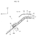
- a passenger compartment material structure 50 pertaining to the third embodiment of the present invention shown in FIG. 12 and FIG. 13 is one in which a cover member 54 serving as an inhibiting portion is used instead of the water guide member 16 with respect to the passenger compartment material structure 10 pertaining to the first embodiment of the present invention described above.
- the cover member 54 is configured by, for example, a resin molded product, a film, or the like and has preventiveness.
- This cover member 54 is formed in a cross-sectional C shape, and the connecting portion 22 of the ceiling material 12 (the portion of the ceiling material 12 on the pillar garnish 14 side) is inserted inside this cover member 54.
- this cover member 54 is tightly adhered to the air barrier film 32. Moreover, the overlap length between the cover member 54 and the upholstery material 28 is a length L4.
- the cover member 54 guides the water to the pillar garnish 14 while blocking the water, so the water W can be inhibited from reaching the end 28A of the upholstery material 28 on the pillar garnish 14 side. Because of this, the water W can be inhibited from seeping out to the passenger compartment inner side of the upholstery material 28, so the attractiveness of the ceiling material 12 can be inhibited from deteriorating.
- the connecting portion 22 of the ceiling material 12 is inserted into the cover member 54, whereby the connecting portion 22 of this ceiling material 12 can be protected.
- the cover member 54 may also be tightly adhered to the upholstery material 28 in addition to the air barrier film 32. By doing this, the cover member 54 becomes fitted together with the connecting portion 22 of the ceiling material 12, so the connecting portion 22 of this ceiling material 12 can be reinforced.
- a passenger compartment material structure 60 pertaining to the fourth embodiment of the present invention shown in FIG. 14 and FIG. 15 is one in which a water absorbing member 64 serving as an inhibiting portion is used instead of the water guide member 16 with respect to the passenger compartment material structure 10 pertaining to the first embodiment of the present invention described above.
- the water absorbing member 64 is configured by, for example, by a sponge, a nonwoven fabric, or the like and is disposed on the surface 32A of the air barrier film 32 on the passenger compartment outer side. Further, the water absorbing member 64 is spaced a length L5 with respect to the end 12A of the ceiling material 12 on the pillar garnish 14 side and has a volume sufficient enough to be able to absorb a quantity of water assumed beforehand.
- the water absorbing member 64 absorbs the water, so the water W can be inhibited from reaching the end 28A of the upholstery material 28 on the pillar garnish 14 side. Because of this, the water W can be inhibited from seeping out to the passenger compartment inner side of the upholstery material 28, so the attractiveness of the ceiling material 12 can be inhibited from deteriorating.
- the passenger compartment material structures 10, 40, 50, and 60 are applied in regard to the ceiling material 12 and the pillar garnish 14 that covers the front pillar 20, but they may also be applied in regard to the ceiling material 12 and a pillar garnish that covers another pillar (e.g., a center pillar, a rear pillar, etc.).
Landscapes
- Engineering & Computer Science (AREA)
- Mechanical Engineering (AREA)
- Vehicle Interior And Exterior Ornaments, Soundproofing, And Insulation (AREA)
- Body Structure For Vehicles (AREA)
Abstract
Description
- The present invention relates to a passenger compartment material structure.
- In
patent document 1, there is disclosed a ceiling material whose air-impermeability is ensured by a hot melt film. -
- Patent Document 1:
JP-ANo. 10-16660 - Patent Document 2:
JP-A No. 2002-67789 - Patent Document 3:
JP-A No. 2003-306131 - Usually, the portion of a ceiling material that is connected to a pillar garnish is set in the lowest position in the ceiling material. For this reason, in a case where dew condensation has formed on the surface of a roof panel on a passenger compartment inner side and water resulting from this dew condensation has dropped onto the ceiling material, this water flows on the ceiling material toward the pillar garnish.
- However, at the portion of the ceiling material that is connected to the pillar garnish, in a case where an end of an upholstery material on the pillar garnish side is exposed, there is the potential for the water that has reached the end of this upholstery material to be sucked up in the upholstery material because of, for example, capillary action or the like and for this water that has been sucked up to seep out to the passenger compartment inner side of the upholstery material. In this case, there is the problem that the attractiveness of the ceiling material deteriorates.
- The present invention has been made in view of the above-described problem, and it is an object thereof to provide a passenger compartment material structure that can inhibit the attractiveness of a ceiling material from deteriorating.
- In order to solve the above-described problem, a passenger compartment material structure pertaining to a first aspect of the present invention includes: a ceiling material that has, in a layered state, an upholstery material and a base material and an air barrier film that are disposed on a passenger compartment outer side with respect to the upholstery material, with the ceiling material covering a roof panel from a passenger compartment inner side; a pillar garnish that is disposed along a lengthwise direction of a pillar that supports the roof panel from an underside of the roof panel, with the pillar garnish covering the pillar from the passenger compartment inner side; and an inhibiting portion that inhibits water flowing on a surface of the air barrier film on the passenger compartment outer side toward the pillar garnish from reaching an end of the upholstery material on the pillar garnish side.
- According to this passenger compartment material structure, even in a case where dew condensation has formed on the surface of the roof panel on the passenger compartment inner side, water resulting from this dew condensation has dropped onto the ceiling material, and this water has flowed on the ceiling material toward the pillar garnish, this water can be inhibited by the inhibiting portion from reaching the end of the upholstery material on the pillar garnish side. Because of this, the water can be inhibited from seeping out to the passenger compartment inner side of the upholstery material, so the attractiveness of the ceiling material can be inhibited from deteriorating.
- In a passenger compartment material structure pertaining to a second aspect of the present invention, the inhibiting portion is a water guide portion that is disposed separately from or integrally with the air barrier film, and is positioned on the passenger compartment outer side with respect to the pillar garnish, and at least part of which projects to a lower end portion side of the pillar garnish with respect to the end of the upholstery material on the pillar garnish side and overlaps the pillar garnish in the lengthwise direction of the pillar.
- According to this passenger compartment material structure, even in a case where the water has flowed on the ceiling material toward the pillar garnish, the water guide portion guides the water to the pillar garnish, so the water can be inhibited from reaching the end of the upholstery material on the pillar garnish side.
- In a passenger compartment material structure pertaining to a third aspect of the present invention, the inhibiting portion is a water guide portion that is disposed on the ceiling material and guides the water flowing on the surface of the air barrier film on the passenger compartment outer side toward the pillar garnish to the pillar garnish.
- According to this passenger compartment material structure, even in a case where the water has flowed on the ceiling material toward the pillar garnish, the water guide portion guides the water to the pillar garnish, so the water can be inhibited from reaching the end of the upholstery material on the pillar garnish side.
- In a passenger compartment material structure pertaining to a fourth aspect of the present invention, the air barrier film is disposed on the passenger compartment outer side with respect to the base material, and the inhibiting portion is a cover member that is formed in a cross-sectional C shape, with the portion of the ceiling material on the pillar garnish side being inserted therein, and that is tightly adhered to at least the air barrier film.
- According to this passenger compartment material structure, even in a case where the water has flowed on the ceiling material toward the pillar garnish, the cover member guides the water to the pillar garnish while blocking the water, so the water can be inhibited from reaching the end of the upholstery material on the pillar garnish side.
- In a passenger compartment material structure pertaining to a fifth aspect of the present invention, the air barrier film is disposed on the passenger compartment outer side with respect to the base material, and the inhibiting portion is a water absorbing member that is disposed on the surface of the air barrier film on the passenger compartment outer side.
- According to this passenger compartment material structure, even in a case where the water has flowed on the ceiling material toward the pillar garnish, the water absorbing member absorbs the water, so the water can be inhibited from reaching the end of the upholstery material on the pillar garnish side.
- As described in detail above, according to the present invention, water can be inhibited by the inhibiting portion from reaching the end of the upholstery material on the pillar garnish side. Because of this, the water can be inhibited from seeping out to the passenger compartment inner side of the upholstery material, so the attractiveness of the ceiling material can be inhibited from deteriorating.
-
-
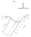
FIG. 1 is a perspective view showing a passenger compartment material structure pertaining to a first embodiment of the present invention as seen from a passenger compartment inner side; -
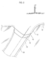
FIG. 2 is a view showing a state in which a pillar garnish has been detached from the passenger compartment material structure shown inFIG. 1 ; -
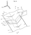
FIG. 3 is a perspective view showing the passenger compartment material structure shown inFIG. 1 as seen from a passenger compartment outer side; -
FIG. 4 is a cross-sectional view taken along line 4-4 inFIG. 3 ; -
FIG. 5 is a view showing a modification of the passenger compartment material structure shown inFIG. 4 ; -
FIG. 6 is a view showing a modification of the passenger compartment material structure shown inFIG. 4 ; -
FIG. 7 is a view showing a modification of the passenger compartment material structure shown inFIG. 4 ; -
FIG. 8 is a view showing a modification of the passenger compartment material structure shown inFIG. 4 ; -
FIG. 9 is a perspective view showing a passenger compartment material structure pertaining to a second embodiment of the present invention as seen from the passenger compartment outer side; -
FIG. 10 is a cross-sectional view taken along line 10-10 inFIG. 9 ; -
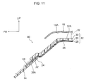
FIG. 11 is a view showing a modification of the passenger compartment material structure shown inFIG. 10 ; -
FIG. 12 is a perspective view showing a passenger compartment material structure pertaining to a third embodiment of the present invention as seen from the passenger compartment outer side; -
FIG. 13 is a cross-sectional view taken along line 13-13 inFIG. 12 ; -
FIG. 14 a perspective view showing a passenger compartment material structure pertaining to a fourth embodiment of the present invention as seen from the passenger compartment outer side; -
FIG. 15 is a cross-sectional view taken along line 15-15 inFIG. 14 ; and -
FIG. 16 is a cross-sectional view of a passenger compartment material structure pertaining to a comparative example. - To begin, a first embodiment of the present invention will be described.
- As shown in
FIG. 1 andFIG. 2 , a passengercompartment material structure 10 pertaining to the first embodiment of the present invention is equipped with aceiling material 12, apillar garnish 14, and awater guide member 16. - The
ceiling material 12 covers aroof panel 18 from a passenger compartment inner side. Afront pillar 20 supports theroof panel 18 from an underside of theroof panel 18, and thepillar garnish 14 is disposed along a lengthwise direction of thisfront pillar 20 and covers thisfront pillar 20 from the passenger compartment inner side. - As shown in
FIG. 3 andFIG. 4 , a connectingportion 22 is formed on thepillar garnish 14 side of theceiling material 12, and a connectingportion 24 is formed on theceiling material 12 side of thepillar garnish 14. The connectingportion 24 is positioned on the passenger compartment inner side with respect to the connectingportion 22 and is superimposed on the connectingportion 22. Further, the connectingportions main body portion 26 of theceiling material 12. - As shown in
FIG. 4 , theceiling material 12 has, in a layered state, anupholstery material 28, abase material 30, and anair barrier film 32. Thebase material 30 is disposed on a passenger compartment outer side with respect to theupholstery material 28, and theair barrier film 32 is disposed on the passenger compartment outer side with respect to thebase material 30. - The
base material 30 is configured by, for example, a heat insulating material such as rigid urethane foam, and theupholstery material 28 is configured by, for example, a nonwoven fabric, a knit, a fabric, or the like. Further, theair barrier film 32 is configured by, for example, resin, paper, or the like. - The
water guide member 16 is configured separately from theair barrier film 32 and is adhered in a state of tight adhesion to asurface 32A of thisair barrier film 32 on the passenger compartment outer side. Thiswater guide member 16 is positioned on the passenger compartment outer side with respect to thepillar garnish 14 and has awater guide portion 34 serving as an inhibiting portion. - The
water guide portion 34 projects to a lower end portion side of thepillar garnish 14 with respect to anend 28A of theupholstery material 28 on thepillar garnish 14 side and overlaps thispillar garnish 14 in the lengthwise direction of thefront pillar 20. That is, the overlap length (projecting length) of thiswater guide portion 34 is a length L1. - The
water guide member 16 is formed by resin molding or is configured to have flexibility, and thewater guide member 16 follows the shape of the connectingportion 20 and is disposed integrally with this connectingportion 22. - Next, the action and effects of the first embodiment of the present invention will be described.
- First, in order to make the action and effects of the first embodiment of the present invention clearer, a comparative example will be described. A passenger
compartment material structure 70 pertaining to a comparative example shown inFIG. 16 is given a configuration where thewater guide member 16 is omitted with respect to the passengercompartment material structure 10 pertaining to the first embodiment of the present invention. - In the passenger
compartment material structure 70 pertaining to this comparative example, in a case where dew condensation has formed on asurface 18A of theroof panel 18 on the passenger compartment inner side and water W resulting from this dew condensation has dropped onto theceiling material 12, this water flows on thesurface 32A of theair barrier film 32 on the passenger compartment outer side toward thepillar garnish 14. - However, at the connecting
portion 22, theend 28A of theupholstery material 28 on thepillar garnish 14 side is exposed. For this reason, there is the potential for the water W that has reached theend 28A of thisupholstery material 28 to be sucked up in theupholstery material 28 because of, for example, capillary action or the like and for this water W that has been sucked up to seep out to the passenger compartment inner side of the upholstery material 28 (there is the potential for seeping water W1 of the water to form). In this case, there is the problem that the attractiveness of theceiling material 12 deteriorates. - In contrast, according to the passenger
compartment material structure 10 pertaining to the first embodiment of the present invention, as shown inFIG. 4 , even in a case where the water W has flowed on thesurface 32A of theair barrier film 32 on the passenger compartment outer side toward thepillar garnish 14, thewater guide portion 34 guides the water W to thepillar garnish 14, so the water W can be inhibited from reaching theend 28A of theupholstery material 28 on thepillar garnish 14 side. Because of this, the water W can be inhibited from seeping out to the passenger compartment inner side of theupholstery material 28, so the attractiveness of theceiling material 12 can be inhibited from deteriorating. - In the present embodiment, the
water guide member 16 is disposed on the passenger compartment outer side with respect to theair barrier film 32, but as shown inFIG. 5 thewater guide member 16 may also be disposed between thebase material 30 and theair barrier film 32. - Further, as shown in
FIG. 6 , thewater guide member 16 may also be disposed between thebase material 30 and theupholstery material 28. In this case, when a long overlap length L2 between thewater guide member 16 and theupholstery material 28 is ensured, the water W can be inhibited from traveling from anend 30A of thebase material 30 through the inside of thebase material 30 and reaching theupholstery material 28 from anupper end 16A side of thewater guide member 16, so this is preferred. - Further, in the present embodiment, the
air barrier film 32 is disposed on the passenger compartment outer side with respect to thebase material 30, but as shown inFIG. 7 andFIG. 8 theair barrier film 32 may also be disposed between thebase material 30 and theupholstery material 28. - Further, in this case, the
water guide member 16 may be disposed between thebase material 30 and theair barrier film 32 as shown inFIG. 7 or may be disposed between theair barrier film 32 and theupholstery material 28 as shown inFIG. 8 . - According to the above modifications also, the
water guide member 34 guides the water W to thepillar garnish 14, so the water W can be inhibited from reaching theend 28A of theupholstery material 28 on thepillar garnish 14 side. - Further, in the above-described embodiment, the distal end side of the
water guide portion 34 is away from thepillar garnish 14, but thewater guide portion 34 may be configured to have flexibility overall so that its distal end side deforms toward thepillar garnish 14 side because of self-weight and contacts thispillar garnish 14. - Next, a second embodiment of the present invention will be described.
- A passenger
compartment material structure 40 pertaining to the second embodiment of the present invention shown inFIG. 9 andFIG. 10 is one in which thewater guide member 16 is omitted with respect to the passengercompartment material structure 10 pertaining to the first embodiment of the present invention described above and is given the following configuration. - That is, the portion of the
air barrier film 32 on thepillar garnish 14 side extends (projects) to the lower end portion side of thepillar garnish 14 with respect to theend 28A of theupholstery material 28 on thepillar garnish 14 side, and this extension portion is awater guide portion 44 serving as an inhibiting portion (that is, thewater guide portion 44 is disposed integrally with the air barrier film 32). - Further, the
water guide portion 44 overlaps thepillar garnish 14 in the lengthwise direction of thefront pillar 20. That is, the overlap length (projecting length) of thiswater guide portion 44 is a length L3. - According to this configuration also, as shown in
FIG. 10 , in a case where the water W has flowed on thesurface 32A of theair barrier film 32 on the passenger compartment outer side toward thepillar garnish 14, thewater guide portion 44 guides the water W to thepillar garnish 14, so the water W can be inhibited from reaching theend 28A of theupholstery material 28 on thepillar garnish 14 side. Because of this, the water W can be inhibited from seeping out to the passenger compartment inner side of theupholstery material 28, so the attractiveness of theceiling material 12 can be inhibited from deteriorating. - In the present embodiment, the
air barrier film 32 that has thewater guide portion 44 is disposed on the passenger compartment outer side with respect to thebase material 30, but as shown inFIG. 11 theair barrier film 32 may also be disposed between thebase material 30 and theupholstery material 28. - According to this modification also, the
water guide portion 44 guides the water W to thepillar garnish 14, so the water W can be inhibited from reaching theend 28A of theupholstery material 28 on thepillar garnish 14 side. - Next, a third embodiment of the present invention will be described.
- A passenger
compartment material structure 50 pertaining to the third embodiment of the present invention shown inFIG. 12 andFIG. 13 is one in which acover member 54 serving as an inhibiting portion is used instead of thewater guide member 16 with respect to the passengercompartment material structure 10 pertaining to the first embodiment of the present invention described above. - The
cover member 54 is configured by, for example, a resin molded product, a film, or the like and has preventiveness. Thiscover member 54 is formed in a cross-sectional C shape, and the connectingportion 22 of the ceiling material 12 (the portion of theceiling material 12 on thepillar garnish 14 side) is inserted inside thiscover member 54. - Further, this
cover member 54 is tightly adhered to theair barrier film 32. Moreover, the overlap length between thecover member 54 and theupholstery material 28 is a length L4. - According to this configuration, even in a case where the water W has flowed on the
surface 32A of theair barrier film 32 on the passenger compartment outer side toward thepillar garnish 14, thecover member 54 guides the water to thepillar garnish 14 while blocking the water, so the water W can be inhibited from reaching theend 28A of theupholstery material 28 on thepillar garnish 14 side. Because of this, the water W can be inhibited from seeping out to the passenger compartment inner side of theupholstery material 28, so the attractiveness of theceiling material 12 can be inhibited from deteriorating. - Further, the connecting
portion 22 of theceiling material 12 is inserted into thecover member 54, whereby the connectingportion 22 of thisceiling material 12 can be protected. - The
cover member 54 may also be tightly adhered to theupholstery material 28 in addition to theair barrier film 32. By doing this, thecover member 54 becomes fitted together with the connectingportion 22 of theceiling material 12, so the connectingportion 22 of thisceiling material 12 can be reinforced. - Next, a fourth embodiment of the present invention will be described.
- A passenger
compartment material structure 60 pertaining to the fourth embodiment of the present invention shown inFIG. 14 andFIG. 15 is one in which awater absorbing member 64 serving as an inhibiting portion is used instead of thewater guide member 16 with respect to the passengercompartment material structure 10 pertaining to the first embodiment of the present invention described above. - The
water absorbing member 64 is configured by, for example, by a sponge, a nonwoven fabric, or the like and is disposed on thesurface 32A of theair barrier film 32 on the passenger compartment outer side. Further, thewater absorbing member 64 is spaced a length L5 with respect to theend 12A of theceiling material 12 on thepillar garnish 14 side and has a volume sufficient enough to be able to absorb a quantity of water assumed beforehand. - According to this configuration, even in a case where the water W has flowed on the
surface 32A of theair barrier film 32 on the passenger compartment outer side toward thepillar garnish 14, thewater absorbing member 64 absorbs the water, so the water W can be inhibited from reaching theend 28A of theupholstery material 28 on thepillar garnish 14 side. Because of this, the water W can be inhibited from seeping out to the passenger compartment inner side of theupholstery material 28, so the attractiveness of theceiling material 12 can be inhibited from deteriorating. - Embodiments of the present invention and modifications thereof have been described above, but the present invention is not limited to the above description and is of course capable of being modified and implemented in a variety of ways other than what has been described above in a range not departing from the gist thereof.
- Further, in each of the embodiments described above, the passenger
compartment material structures ceiling material 12 and thepillar garnish 14 that covers thefront pillar 20, but they may also be applied in regard to theceiling material 12 and a pillar garnish that covers another pillar (e.g., a center pillar, a rear pillar, etc.).
Claims (5)
- A passenger compartment material structure comprising:a ceiling material that has, in a layered state, an upholstery material and a base material and an air barrier film that are disposed on a passenger compartment outer side with respect to the upholstery material, with the ceiling material covering a roof panel from a passenger compartment inner side;a pillar garnish that is disposed along a lengthwise direction of a pillar that supports the roof panel from an underside of the roof panel, with the pillar garnish covering the pillar from the passenger compartment inner side; andan inhibiting portion that inhibits water flowing on a surface of the air barrier film on the passenger compartment outer side toward the pillar garnish from reaching an end of the upholstery material on the pillar garnish side.
- The passenger compartment material structure according to claim 1, wherein the inhibiting portion is a water guide portion that is disposed separately from or integrally with the air barrier film, and is positioned on the passenger compartment outer side with respect to the pillar garnish, and at least part of which projects to a lower end portion side of the pillar garnish with respect to the end of the upholstery material on the pillar garnish side and overlaps the pillar garnish in the lengthwise direction of the pillar.
- The passenger compartment material structure according to claim 1, wherein the inhibiting portion is a water guide portion that is disposed on the ceiling material and guides the water flowing on the surface of the air barrier film on the passenger compartment outer side toward the pillar garnish to the pillar garnish.
- The passenger compartment material structure according to claim 1, wherein
the air barrier film is disposed on the passenger compartment outer side with respect to the base material, and
the inhibiting portion is a cover member that is formed in a cross-sectional C shape, with the portion of the ceiling material on the pillar garnish side being inserted therein, and that is tightly adhered to at least the air barrier film. - The passenger compartment material structure according to claim 1, wherein
the air barrier film is disposed on the passenger compartment outer side with respect to the base material, and
the inhibiting portion is a water absorbing member that is disposed on the surface of the air barrier film on the passenger compartment outer side.
Applications Claiming Priority (1)
| Application Number | Priority Date | Filing Date | Title |
|---|---|---|---|
| PCT/JP2009/057144 WO2010116495A1 (en) | 2009-04-07 | 2009-04-07 | Passenger compartment material structure |
Publications (3)
| Publication Number | Publication Date |
|---|---|
| EP2418125A1 true EP2418125A1 (en) | 2012-02-15 |
| EP2418125A4 EP2418125A4 (en) | 2012-12-05 |
| EP2418125B1 EP2418125B1 (en) | 2013-10-16 |
Family
ID=42935804
Family Applications (1)
| Application Number | Title | Priority Date | Filing Date |
|---|---|---|---|
| EP09843005.1A Not-in-force EP2418125B1 (en) | 2009-04-07 | 2009-04-07 | Passenger compartment material structure |
Country Status (7)
| Country | Link |
|---|---|
| US (1) | US8474904B2 (en) |
| EP (1) | EP2418125B1 (en) |
| JP (1) | JP5170307B2 (en) |
| CN (1) | CN102378707B (en) |
| CA (1) | CA2758094C (en) |
| RU (1) | RU2481207C1 (en) |
| WO (1) | WO2010116495A1 (en) |
Families Citing this family (6)
| Publication number | Priority date | Publication date | Assignee | Title |
|---|---|---|---|---|
| JP5445710B2 (en) * | 2013-05-27 | 2014-03-19 | 三菱自動車工業株式会社 | Vehicle headlining and interior structure including the same |
| US9302710B2 (en) | 2014-08-07 | 2016-04-05 | Honda Motor Co., Ltd. | Front pillar attachment for a vehicle body |
| JP6334335B2 (en) * | 2014-09-04 | 2018-05-30 | トヨタ紡織株式会社 | Front pillar garnish |
| JP6313694B2 (en) * | 2014-10-30 | 2018-04-18 | トヨタ紡織株式会社 | Interior materials for vehicles |
| US20170136966A1 (en) * | 2015-11-13 | 2017-05-18 | Ford Global Technologies, Llc | Decklid trim interlocking feature |
| US10737561B2 (en) * | 2018-05-30 | 2020-08-11 | Nissan North America, Inc. | Sunroof structure |
Family Cites Families (15)
| Publication number | Priority date | Publication date | Assignee | Title |
|---|---|---|---|---|
| JPH0653478B2 (en) | 1985-03-13 | 1994-07-20 | スズキ株式会社 | Terminal structure of automobile ceiling interior materials |
| JPH041056A (en) | 1990-04-19 | 1992-01-06 | Canon Inc | Ink-jet recording device |
| JPH041056U (en) * | 1990-04-19 | 1992-01-07 | ||
| JPH0584577A (en) | 1991-09-26 | 1993-04-06 | Sumitomo Metal Ind Ltd | Overlap fillet welding method for resin composite type metal plate |
| JPH0584577U (en) * | 1992-04-22 | 1993-11-16 | 市光工業株式会社 | Raindrop prevention structure in vehicle equipment |
| JPH1016660A (en) | 1996-06-29 | 1998-01-20 | Ikeda Bussan Co Ltd | Automobile ceiling material |
| JP3607982B2 (en) * | 2000-05-17 | 2005-01-05 | トヨタ自動車株式会社 | Car body upper structure |
| EP1177949A1 (en) * | 2000-08-01 | 2002-02-06 | Recticel | Method for manufacturing a trim part for the interior of an automobile vehicle or at least a skin therefor |
| JP2002067789A (en) | 2000-09-05 | 2002-03-08 | Yazaki Corp | Lamp unit wire connection structure |
| JP2003306131A (en) | 2002-04-15 | 2003-10-28 | Nissan Motor Co Ltd | Rear body structure of vehicle |
| US6832810B2 (en) * | 2002-07-05 | 2004-12-21 | Lear Corporation | Flexible headliner for automotive vehicle |
| US7309521B2 (en) * | 2002-12-19 | 2007-12-18 | International Automotive Components Group North America, Inc. | Headliner apparatus with foam imbedded NVH pad |
| US6887552B2 (en) * | 2002-12-19 | 2005-05-03 | Lear Corporation | Structural headliner assembly |
| JP2008143455A (en) | 2006-12-13 | 2008-06-26 | Kasai Kogyo Co Ltd | Skin terminal treatment method for sunroof opening |
| JP2009051328A (en) | 2007-08-25 | 2009-03-12 | Suzuki Motor Corp | Pillar trim drainage structure |
-
2009
- 2009-04-07 WO PCT/JP2009/057144 patent/WO2010116495A1/en not_active Ceased
- 2009-04-07 CA CA2758094A patent/CA2758094C/en active Active
- 2009-04-07 EP EP09843005.1A patent/EP2418125B1/en not_active Not-in-force
- 2009-04-07 RU RU2011143068/11A patent/RU2481207C1/en active
- 2009-04-07 CN CN200980158516.6A patent/CN102378707B/en not_active Expired - Fee Related
- 2009-04-07 JP JP2011508133A patent/JP5170307B2/en not_active Expired - Fee Related
- 2009-04-07 US US13/263,100 patent/US8474904B2/en active Active
Non-Patent Citations (2)
| Title |
|---|
| No further relevant documents disclosed * |
| See also references of WO2010116495A1 * |
Also Published As
| Publication number | Publication date |
|---|---|
| US20120025567A1 (en) | 2012-02-02 |
| EP2418125B1 (en) | 2013-10-16 |
| WO2010116495A1 (en) | 2010-10-14 |
| US8474904B2 (en) | 2013-07-02 |
| CA2758094C (en) | 2013-06-25 |
| EP2418125A4 (en) | 2012-12-05 |
| JPWO2010116495A1 (en) | 2012-10-11 |
| RU2481207C1 (en) | 2013-05-10 |
| CN102378707B (en) | 2013-09-11 |
| CA2758094A1 (en) | 2010-10-14 |
| CN102378707A (en) | 2012-03-14 |
| JP5170307B2 (en) | 2013-03-27 |
Similar Documents
| Publication | Publication Date | Title |
|---|---|---|
| CA2758094C (en) | Passenger compartment material structure | |
| CN103140411B (en) | Resin roof attachment structure | |
| US20080258507A1 (en) | System to establish a trim edge for a vehicle roof window | |
| US9142944B2 (en) | Case | |
| US9505356B2 (en) | Vehicular interior part | |
| US20090145041A1 (en) | Door for the vehicle | |
| US9403507B2 (en) | Vehicular interior member assembly and vehicular interior part | |
| EP2468580A1 (en) | Interior material mounting structure | |
| CN102452365A (en) | Cowl louver sealing structure | |
| US8770652B2 (en) | Upper vehicle body structure of vehicle with sun roof | |
| US8002340B2 (en) | Joint structure for fixing between sunroof and headliner | |
| CN109987154B (en) | Vehicle body structure | |
| CN102039797A (en) | Mounting vehicle body structure of vehicle window insertion strip | |
| JP6588202B2 (en) | Electronic equipment | |
| US20220360060A1 (en) | Protector for wire harness | |
| US8991910B2 (en) | Water drain valve for the water box of a motor vehicle | |
| JP2011031686A (en) | Door structure for vehicle | |
| JP2010076605A (en) | End structure of roof member | |
| JP4818308B2 (en) | Tailgate drainage structure | |
| KR20210035889A (en) | Vehicle sound absorbing material | |
| US8366186B2 (en) | Headliner compression stiffener | |
| JP6245694B2 (en) | Luggage mat | |
| JP2008024055A (en) | Interior materials for vehicles | |
| KR20140077708A (en) | Pillar trim for vehicle | |
| JP5647422B2 (en) | trim |
Legal Events
| Date | Code | Title | Description |
|---|---|---|---|
| PUAI | Public reference made under article 153(3) epc to a published international application that has entered the european phase |
Free format text: ORIGINAL CODE: 0009012 |
|
| 17P | Request for examination filed |
Effective date: 20111021 |
|
| AK | Designated contracting states |
Kind code of ref document: A1 Designated state(s): AT BE BG CH CY CZ DE DK EE ES FI FR GB GR HR HU IE IS IT LI LT LU LV MC MK MT NL NO PL PT RO SE SI SK TR |
|
| DAX | Request for extension of the european patent (deleted) | ||
| A4 | Supplementary search report drawn up and despatched |
Effective date: 20121105 |
|
| RIC1 | Information provided on ipc code assigned before grant |
Ipc: B60R 13/02 20060101AFI20121029BHEP Ipc: B60R 13/07 20060101ALI20121029BHEP |
|
| RAP1 | Party data changed (applicant data changed or rights of an application transferred) |
Owner name: TOYOTA JIDOSHA KABUSHIKI KAISHA |
|
| GRAP | Despatch of communication of intention to grant a patent |
Free format text: ORIGINAL CODE: EPIDOSNIGR1 |
|
| INTG | Intention to grant announced |
Effective date: 20130531 |
|
| GRAS | Grant fee paid |
Free format text: ORIGINAL CODE: EPIDOSNIGR3 |
|
| GRAA | (expected) grant |
Free format text: ORIGINAL CODE: 0009210 |
|
| AK | Designated contracting states |
Kind code of ref document: B1 Designated state(s): AT BE BG CH CY CZ DE DK EE ES FI FR GB GR HR HU IE IS IT LI LT LU LV MC MK MT NL NO PL PT RO SE SI SK TR |
|
| REG | Reference to a national code |
Ref country code: GB Ref legal event code: FG4D |
|
| REG | Reference to a national code |
Ref country code: CH Ref legal event code: EP |
|
| REG | Reference to a national code |
Ref country code: IE Ref legal event code: FG4D |
|
| REG | Reference to a national code |
Ref country code: AT Ref legal event code: REF Ref document number: 636318 Country of ref document: AT Kind code of ref document: T Effective date: 20131115 |
|
| REG | Reference to a national code |
Ref country code: DE Ref legal event code: R096 Ref document number: 602009019550 Country of ref document: DE Effective date: 20131212 |
|
| REG | Reference to a national code |
Ref country code: SE Ref legal event code: TRGR |
|
| REG | Reference to a national code |
Ref country code: NL Ref legal event code: VDEP Effective date: 20131016 |
|
| REG | Reference to a national code |
Ref country code: NO Ref legal event code: T2 Effective date: 20131016 |
|
| REG | Reference to a national code |
Ref country code: AT Ref legal event code: MK05 Ref document number: 636318 Country of ref document: AT Kind code of ref document: T Effective date: 20131016 |
|
| REG | Reference to a national code |
Ref country code: LT Ref legal event code: MG4D |
|
| PG25 | Lapsed in a contracting state [announced via postgrant information from national office to epo] |
Ref country code: IS Free format text: LAPSE BECAUSE OF FAILURE TO SUBMIT A TRANSLATION OF THE DESCRIPTION OR TO PAY THE FEE WITHIN THE PRESCRIBED TIME-LIMIT Effective date: 20140216 Ref country code: FI Free format text: LAPSE BECAUSE OF FAILURE TO SUBMIT A TRANSLATION OF THE DESCRIPTION OR TO PAY THE FEE WITHIN THE PRESCRIBED TIME-LIMIT Effective date: 20131016 Ref country code: LT Free format text: LAPSE BECAUSE OF FAILURE TO SUBMIT A TRANSLATION OF THE DESCRIPTION OR TO PAY THE FEE WITHIN THE PRESCRIBED TIME-LIMIT Effective date: 20131016 Ref country code: NL Free format text: LAPSE BECAUSE OF FAILURE TO SUBMIT A TRANSLATION OF THE DESCRIPTION OR TO PAY THE FEE WITHIN THE PRESCRIBED TIME-LIMIT Effective date: 20131016 Ref country code: BE Free format text: LAPSE BECAUSE OF FAILURE TO SUBMIT A TRANSLATION OF THE DESCRIPTION OR TO PAY THE FEE WITHIN THE PRESCRIBED TIME-LIMIT Effective date: 20131016 Ref country code: HR Free format text: LAPSE BECAUSE OF FAILURE TO SUBMIT A TRANSLATION OF THE DESCRIPTION OR TO PAY THE FEE WITHIN THE PRESCRIBED TIME-LIMIT Effective date: 20131016 |
|
| PG25 | Lapsed in a contracting state [announced via postgrant information from national office to epo] |
Ref country code: AT Free format text: LAPSE BECAUSE OF FAILURE TO SUBMIT A TRANSLATION OF THE DESCRIPTION OR TO PAY THE FEE WITHIN THE PRESCRIBED TIME-LIMIT Effective date: 20131016 Ref country code: CY Free format text: LAPSE BECAUSE OF FAILURE TO SUBMIT A TRANSLATION OF THE DESCRIPTION OR TO PAY THE FEE WITHIN THE PRESCRIBED TIME-LIMIT Effective date: 20131016 Ref country code: ES Free format text: LAPSE BECAUSE OF FAILURE TO SUBMIT A TRANSLATION OF THE DESCRIPTION OR TO PAY THE FEE WITHIN THE PRESCRIBED TIME-LIMIT Effective date: 20131016 Ref country code: LV Free format text: LAPSE BECAUSE OF FAILURE TO SUBMIT A TRANSLATION OF THE DESCRIPTION OR TO PAY THE FEE WITHIN THE PRESCRIBED TIME-LIMIT Effective date: 20131016 |
|
| PG25 | Lapsed in a contracting state [announced via postgrant information from national office to epo] |
Ref country code: PT Free format text: LAPSE BECAUSE OF FAILURE TO SUBMIT A TRANSLATION OF THE DESCRIPTION OR TO PAY THE FEE WITHIN THE PRESCRIBED TIME-LIMIT Effective date: 20140217 |
|
| REG | Reference to a national code |
Ref country code: DE Ref legal event code: R097 Ref document number: 602009019550 Country of ref document: DE |
|
| PG25 | Lapsed in a contracting state [announced via postgrant information from national office to epo] |
Ref country code: EE Free format text: LAPSE BECAUSE OF FAILURE TO SUBMIT A TRANSLATION OF THE DESCRIPTION OR TO PAY THE FEE WITHIN THE PRESCRIBED TIME-LIMIT Effective date: 20131016 |
|
| PLBE | No opposition filed within time limit |
Free format text: ORIGINAL CODE: 0009261 |
|
| STAA | Information on the status of an ep patent application or granted ep patent |
Free format text: STATUS: NO OPPOSITION FILED WITHIN TIME LIMIT |
|
| PG25 | Lapsed in a contracting state [announced via postgrant information from national office to epo] |
Ref country code: PL Free format text: LAPSE BECAUSE OF FAILURE TO SUBMIT A TRANSLATION OF THE DESCRIPTION OR TO PAY THE FEE WITHIN THE PRESCRIBED TIME-LIMIT Effective date: 20131016 Ref country code: RO Free format text: LAPSE BECAUSE OF FAILURE TO SUBMIT A TRANSLATION OF THE DESCRIPTION OR TO PAY THE FEE WITHIN THE PRESCRIBED TIME-LIMIT Effective date: 20131016 Ref country code: IT Free format text: LAPSE BECAUSE OF FAILURE TO SUBMIT A TRANSLATION OF THE DESCRIPTION OR TO PAY THE FEE WITHIN THE PRESCRIBED TIME-LIMIT Effective date: 20131016 Ref country code: CZ Free format text: LAPSE BECAUSE OF FAILURE TO SUBMIT A TRANSLATION OF THE DESCRIPTION OR TO PAY THE FEE WITHIN THE PRESCRIBED TIME-LIMIT Effective date: 20131016 Ref country code: SK Free format text: LAPSE BECAUSE OF FAILURE TO SUBMIT A TRANSLATION OF THE DESCRIPTION OR TO PAY THE FEE WITHIN THE PRESCRIBED TIME-LIMIT Effective date: 20131016 |
|
| 26N | No opposition filed |
Effective date: 20140717 |
|
| PG25 | Lapsed in a contracting state [announced via postgrant information from national office to epo] |
Ref country code: DK Free format text: LAPSE BECAUSE OF FAILURE TO SUBMIT A TRANSLATION OF THE DESCRIPTION OR TO PAY THE FEE WITHIN THE PRESCRIBED TIME-LIMIT Effective date: 20131016 |
|
| REG | Reference to a national code |
Ref country code: DE Ref legal event code: R097 Ref document number: 602009019550 Country of ref document: DE Effective date: 20140717 |
|
| PG25 | Lapsed in a contracting state [announced via postgrant information from national office to epo] |
Ref country code: MC Free format text: LAPSE BECAUSE OF FAILURE TO SUBMIT A TRANSLATION OF THE DESCRIPTION OR TO PAY THE FEE WITHIN THE PRESCRIBED TIME-LIMIT Effective date: 20131016 Ref country code: LU Free format text: LAPSE BECAUSE OF FAILURE TO SUBMIT A TRANSLATION OF THE DESCRIPTION OR TO PAY THE FEE WITHIN THE PRESCRIBED TIME-LIMIT Effective date: 20140407 |
|
| REG | Reference to a national code |
Ref country code: CH Ref legal event code: PL |
|
| GBPC | Gb: european patent ceased through non-payment of renewal fee |
Effective date: 20140407 |
|
| REG | Reference to a national code |
Ref country code: FR Ref legal event code: ST Effective date: 20141231 |
|
| REG | Reference to a national code |
Ref country code: DE Ref legal event code: R084 Ref document number: 602009019550 Country of ref document: DE |
|
| REG | Reference to a national code |
Ref country code: IE Ref legal event code: MM4A |
|
| PG25 | Lapsed in a contracting state [announced via postgrant information from national office to epo] |
Ref country code: LI Free format text: LAPSE BECAUSE OF NON-PAYMENT OF DUE FEES Effective date: 20140430 Ref country code: CH Free format text: LAPSE BECAUSE OF NON-PAYMENT OF DUE FEES Effective date: 20140430 Ref country code: GB Free format text: LAPSE BECAUSE OF NON-PAYMENT OF DUE FEES Effective date: 20140407 |
|
| PG25 | Lapsed in a contracting state [announced via postgrant information from national office to epo] |
Ref country code: SI Free format text: LAPSE BECAUSE OF FAILURE TO SUBMIT A TRANSLATION OF THE DESCRIPTION OR TO PAY THE FEE WITHIN THE PRESCRIBED TIME-LIMIT Effective date: 20131016 Ref country code: FR Free format text: LAPSE BECAUSE OF NON-PAYMENT OF DUE FEES Effective date: 20140430 |
|
| REG | Reference to a national code |
Ref country code: DE Ref legal event code: R084 Ref document number: 602009019550 Country of ref document: DE Effective date: 20150126 |
|
| PG25 | Lapsed in a contracting state [announced via postgrant information from national office to epo] |
Ref country code: IE Free format text: LAPSE BECAUSE OF NON-PAYMENT OF DUE FEES Effective date: 20140407 |
|
| PG25 | Lapsed in a contracting state [announced via postgrant information from national office to epo] |
Ref country code: MT Free format text: LAPSE BECAUSE OF FAILURE TO SUBMIT A TRANSLATION OF THE DESCRIPTION OR TO PAY THE FEE WITHIN THE PRESCRIBED TIME-LIMIT Effective date: 20131016 |
|
| PG25 | Lapsed in a contracting state [announced via postgrant information from national office to epo] |
Ref country code: GR Free format text: LAPSE BECAUSE OF FAILURE TO SUBMIT A TRANSLATION OF THE DESCRIPTION OR TO PAY THE FEE WITHIN THE PRESCRIBED TIME-LIMIT Effective date: 20140117 Ref country code: BG Free format text: LAPSE BECAUSE OF FAILURE TO SUBMIT A TRANSLATION OF THE DESCRIPTION OR TO PAY THE FEE WITHIN THE PRESCRIBED TIME-LIMIT Effective date: 20131016 |
|
| PG25 | Lapsed in a contracting state [announced via postgrant information from national office to epo] |
Ref country code: HU Free format text: LAPSE BECAUSE OF FAILURE TO SUBMIT A TRANSLATION OF THE DESCRIPTION OR TO PAY THE FEE WITHIN THE PRESCRIBED TIME-LIMIT; INVALID AB INITIO Effective date: 20090407 Ref country code: TR Free format text: LAPSE BECAUSE OF FAILURE TO SUBMIT A TRANSLATION OF THE DESCRIPTION OR TO PAY THE FEE WITHIN THE PRESCRIBED TIME-LIMIT Effective date: 20131016 |
|
| PG25 | Lapsed in a contracting state [announced via postgrant information from national office to epo] |
Ref country code: MK Free format text: LAPSE BECAUSE OF FAILURE TO SUBMIT A TRANSLATION OF THE DESCRIPTION OR TO PAY THE FEE WITHIN THE PRESCRIBED TIME-LIMIT Effective date: 20131016 |
|
| PGFP | Annual fee paid to national office [announced via postgrant information from national office to epo] |
Ref country code: SE Payment date: 20230227 Year of fee payment: 15 |
|
| P01 | Opt-out of the competence of the unified patent court (upc) registered |
Effective date: 20230427 |
|
| PGFP | Annual fee paid to national office [announced via postgrant information from national office to epo] |
Ref country code: NO Payment date: 20230412 Year of fee payment: 15 Ref country code: DE Payment date: 20230228 Year of fee payment: 15 |
|
| REG | Reference to a national code |
Ref country code: DE Ref legal event code: R119 Ref document number: 602009019550 Country of ref document: DE |
|
| REG | Reference to a national code |
Ref country code: SE Ref legal event code: EUG |
|
| PG25 | Lapsed in a contracting state [announced via postgrant information from national office to epo] |
Ref country code: DE Free format text: LAPSE BECAUSE OF NON-PAYMENT OF DUE FEES Effective date: 20241105 |
|
| PG25 | Lapsed in a contracting state [announced via postgrant information from national office to epo] |
Ref country code: NO Free format text: LAPSE BECAUSE OF NON-PAYMENT OF DUE FEES Effective date: 20240430 |
|
| PG25 | Lapsed in a contracting state [announced via postgrant information from national office to epo] |
Ref country code: NO Free format text: LAPSE BECAUSE OF NON-PAYMENT OF DUE FEES Effective date: 20240430 Ref country code: DE Free format text: LAPSE BECAUSE OF NON-PAYMENT OF DUE FEES Effective date: 20241105 |
|
| PG25 | Lapsed in a contracting state [announced via postgrant information from national office to epo] |
Ref country code: SE Free format text: LAPSE BECAUSE OF NON-PAYMENT OF DUE FEES Effective date: 20240408 |