EP2416699B1 - Dispositif et procédé de mesure d'un composant sanguin dans le sang pour un dispositif extracorporel de traitement du sang - Google Patents
Dispositif et procédé de mesure d'un composant sanguin dans le sang pour un dispositif extracorporel de traitement du sang Download PDFInfo
- Publication number
- EP2416699B1 EP2416699B1 EP10722927.0A EP10722927A EP2416699B1 EP 2416699 B1 EP2416699 B1 EP 2416699B1 EP 10722927 A EP10722927 A EP 10722927A EP 2416699 B1 EP2416699 B1 EP 2416699B1
- Authority
- EP
- European Patent Office
- Prior art keywords
- blood
- measurement
- electromagnetic radiation
- pump
- shut
- Prior art date
- Legal status (The legal status is an assumption and is not a legal conclusion. Google has not performed a legal analysis and makes no representation as to the accuracy of the status listed.)
- Active
Links
- 210000004369 blood Anatomy 0.000 title claims description 154
- 239000008280 blood Substances 0.000 title claims description 154
- 238000011282 treatment Methods 0.000 title claims description 24
- 238000000034 method Methods 0.000 title description 22
- 239000000470 constituent Substances 0.000 title description 3
- 238000005259 measurement Methods 0.000 claims description 84
- WQZGKKKJIJFFOK-GASJEMHNSA-N Glucose Natural products OC[C@H]1OC(O)[C@H](O)[C@@H](O)[C@@H]1O WQZGKKKJIJFFOK-GASJEMHNSA-N 0.000 claims description 51
- 239000008103 glucose Substances 0.000 claims description 51
- 239000012503 blood component Substances 0.000 claims description 17
- 230000005670 electromagnetic radiation Effects 0.000 claims description 17
- 230000008859 change Effects 0.000 claims description 8
- 239000012528 membrane Substances 0.000 claims description 7
- 239000012530 fluid Substances 0.000 claims description 5
- 125000002791 glucosyl group Chemical group C1([C@H](O)[C@@H](O)[C@H](O)[C@H](O1)CO)* 0.000 claims 1
- 230000005540 biological transmission Effects 0.000 description 25
- 239000000385 dialysis solution Substances 0.000 description 19
- 230000017531 blood circulation Effects 0.000 description 18
- 238000004458 analytical method Methods 0.000 description 10
- 108010054147 Hemoglobins Proteins 0.000 description 9
- 102000001554 Hemoglobins Human genes 0.000 description 9
- 238000000502 dialysis Methods 0.000 description 7
- 230000036770 blood supply Effects 0.000 description 6
- 238000011144 upstream manufacturing Methods 0.000 description 6
- 239000002473 artificial blood Substances 0.000 description 5
- 239000000306 component Substances 0.000 description 5
- 238000001631 haemodialysis Methods 0.000 description 5
- 230000000322 hemodialysis Effects 0.000 description 5
- 239000007788 liquid Substances 0.000 description 5
- 239000000126 substance Substances 0.000 description 5
- 230000006399 behavior Effects 0.000 description 4
- 238000002615 hemofiltration Methods 0.000 description 4
- 206010012601 diabetes mellitus Diseases 0.000 description 3
- 238000000108 ultra-filtration Methods 0.000 description 3
- 241000283690 Bos taurus Species 0.000 description 2
- 108010085686 Hemoglobin C Proteins 0.000 description 2
- 230000009102 absorption Effects 0.000 description 2
- 238000010521 absorption reaction Methods 0.000 description 2
- 230000007423 decrease Effects 0.000 description 2
- 210000003743 erythrocyte Anatomy 0.000 description 2
- 238000000691 measurement method Methods 0.000 description 2
- 230000003287 optical effect Effects 0.000 description 2
- 238000012545 processing Methods 0.000 description 2
- 239000000243 solution Substances 0.000 description 2
- 238000002560 therapeutic procedure Methods 0.000 description 2
- 208000001647 Renal Insufficiency Diseases 0.000 description 1
- QVGXLLKOCUKJST-UHFFFAOYSA-N atomic oxygen Chemical compound [O] QVGXLLKOCUKJST-UHFFFAOYSA-N 0.000 description 1
- 230000008901 benefit Effects 0.000 description 1
- 208000020832 chronic kidney disease Diseases 0.000 description 1
- 208000022831 chronic renal failure syndrome Diseases 0.000 description 1
- 230000004087 circulation Effects 0.000 description 1
- 238000012937 correction Methods 0.000 description 1
- 230000001419 dependent effect Effects 0.000 description 1
- 238000011026 diafiltration Methods 0.000 description 1
- 238000003745 diagnosis Methods 0.000 description 1
- 238000009792 diffusion process Methods 0.000 description 1
- 230000008034 disappearance Effects 0.000 description 1
- 238000011156 evaluation Methods 0.000 description 1
- 230000006870 function Effects 0.000 description 1
- 230000005484 gravity Effects 0.000 description 1
- 238000005534 hematocrit Methods 0.000 description 1
- 239000007924 injection Substances 0.000 description 1
- 238000002347 injection Methods 0.000 description 1
- 201000006370 kidney failure Diseases 0.000 description 1
- 238000009533 lab test Methods 0.000 description 1
- 238000004519 manufacturing process Methods 0.000 description 1
- 238000013507 mapping Methods 0.000 description 1
- 238000012544 monitoring process Methods 0.000 description 1
- 229910052760 oxygen Inorganic materials 0.000 description 1
- 239000001301 oxygen Substances 0.000 description 1
- 230000009467 reduction Effects 0.000 description 1
- 239000013049 sediment Substances 0.000 description 1
- 238000004611 spectroscopical analysis Methods 0.000 description 1
- 238000006467 substitution reaction Methods 0.000 description 1
- 230000035488 systolic blood pressure Effects 0.000 description 1
- 239000012780 transparent material Substances 0.000 description 1
- 230000002485 urinary effect Effects 0.000 description 1
- XLYOFNOQVPJJNP-UHFFFAOYSA-N water Substances O XLYOFNOQVPJJNP-UHFFFAOYSA-N 0.000 description 1
Images


Classifications
-
- A—HUMAN NECESSITIES
- A61—MEDICAL OR VETERINARY SCIENCE; HYGIENE
- A61M—DEVICES FOR INTRODUCING MEDIA INTO, OR ONTO, THE BODY; DEVICES FOR TRANSDUCING BODY MEDIA OR FOR TAKING MEDIA FROM THE BODY; DEVICES FOR PRODUCING OR ENDING SLEEP OR STUPOR
- A61M1/00—Suction or pumping devices for medical purposes; Devices for carrying-off, for treatment of, or for carrying-over, body-liquids; Drainage systems
- A61M1/14—Dialysis systems; Artificial kidneys; Blood oxygenators ; Reciprocating systems for treatment of body fluids, e.g. single needle systems for hemofiltration or pheresis
- A61M1/16—Dialysis systems; Artificial kidneys; Blood oxygenators ; Reciprocating systems for treatment of body fluids, e.g. single needle systems for hemofiltration or pheresis with membranes
-
- A—HUMAN NECESSITIES
- A61—MEDICAL OR VETERINARY SCIENCE; HYGIENE
- A61B—DIAGNOSIS; SURGERY; IDENTIFICATION
- A61B5/00—Measuring for diagnostic purposes; Identification of persons
- A61B5/145—Measuring characteristics of blood in vivo, e.g. gas concentration, pH value; Measuring characteristics of body fluids or tissues, e.g. interstitial fluid, cerebral tissue
- A61B5/1455—Measuring characteristics of blood in vivo, e.g. gas concentration, pH value; Measuring characteristics of body fluids or tissues, e.g. interstitial fluid, cerebral tissue using optical sensors, e.g. spectral photometrical oximeters
- A61B5/14551—Measuring characteristics of blood in vivo, e.g. gas concentration, pH value; Measuring characteristics of body fluids or tissues, e.g. interstitial fluid, cerebral tissue using optical sensors, e.g. spectral photometrical oximeters for measuring blood gases
- A61B5/14557—Measuring characteristics of blood in vivo, e.g. gas concentration, pH value; Measuring characteristics of body fluids or tissues, e.g. interstitial fluid, cerebral tissue using optical sensors, e.g. spectral photometrical oximeters for measuring blood gases specially adapted to extracorporeal circuits
-
- A—HUMAN NECESSITIES
- A61—MEDICAL OR VETERINARY SCIENCE; HYGIENE
- A61M—DEVICES FOR INTRODUCING MEDIA INTO, OR ONTO, THE BODY; DEVICES FOR TRANSDUCING BODY MEDIA OR FOR TAKING MEDIA FROM THE BODY; DEVICES FOR PRODUCING OR ENDING SLEEP OR STUPOR
- A61M1/00—Suction or pumping devices for medical purposes; Devices for carrying-off, for treatment of, or for carrying-over, body-liquids; Drainage systems
- A61M1/36—Other treatment of blood in a by-pass of the natural circulatory system, e.g. temperature adaptation, irradiation ; Extra-corporeal blood circuits
- A61M1/3607—Regulation parameters
- A61M1/3609—Physical characteristics of the blood, e.g. haematocrit, urea
- A61M1/361—Physical characteristics of the blood, e.g. haematocrit, urea before treatment
-
- A—HUMAN NECESSITIES
- A61—MEDICAL OR VETERINARY SCIENCE; HYGIENE
- A61B—DIAGNOSIS; SURGERY; IDENTIFICATION
- A61B5/00—Measuring for diagnostic purposes; Identification of persons
- A61B5/145—Measuring characteristics of blood in vivo, e.g. gas concentration, pH value; Measuring characteristics of body fluids or tissues, e.g. interstitial fluid, cerebral tissue
- A61B5/14532—Measuring characteristics of blood in vivo, e.g. gas concentration, pH value; Measuring characteristics of body fluids or tissues, e.g. interstitial fluid, cerebral tissue for measuring glucose, e.g. by tissue impedance measurement
-
- A—HUMAN NECESSITIES
- A61—MEDICAL OR VETERINARY SCIENCE; HYGIENE
- A61M—DEVICES FOR INTRODUCING MEDIA INTO, OR ONTO, THE BODY; DEVICES FOR TRANSDUCING BODY MEDIA OR FOR TAKING MEDIA FROM THE BODY; DEVICES FOR PRODUCING OR ENDING SLEEP OR STUPOR
- A61M2205/00—General characteristics of the apparatus
- A61M2205/33—Controlling, regulating or measuring
- A61M2205/3317—Electromagnetic, inductive or dielectric measuring means
-
- A—HUMAN NECESSITIES
- A61—MEDICAL OR VETERINARY SCIENCE; HYGIENE
- A61M—DEVICES FOR INTRODUCING MEDIA INTO, OR ONTO, THE BODY; DEVICES FOR TRANSDUCING BODY MEDIA OR FOR TAKING MEDIA FROM THE BODY; DEVICES FOR PRODUCING OR ENDING SLEEP OR STUPOR
- A61M2205/00—General characteristics of the apparatus
- A61M2205/33—Controlling, regulating or measuring
- A61M2205/3324—PH measuring means
-
- A—HUMAN NECESSITIES
- A61—MEDICAL OR VETERINARY SCIENCE; HYGIENE
- A61M—DEVICES FOR INTRODUCING MEDIA INTO, OR ONTO, THE BODY; DEVICES FOR TRANSDUCING BODY MEDIA OR FOR TAKING MEDIA FROM THE BODY; DEVICES FOR PRODUCING OR ENDING SLEEP OR STUPOR
- A61M2230/00—Measuring parameters of the user
- A61M2230/30—Blood pressure
Definitions
- the invention relates to a device for measuring a blood constituent in the blood for an extracorporeal blood treatment device comprising a dialyzer or filter subdivided by a semipermeable membrane into a first chamber and a second chamber and a tubing system having tubing permeable to electromagnetic radiation.
- hemodialysis In the case of chronic renal failure, various procedures for extracorporeal blood treatment and cleansing are used to remove urinary-excreted substances and to remove fluids.
- the patient's blood In hemodialysis, the patient's blood is purified outside the body in a dialyzer.
- the dialyzer has a blood chamber and a dialysis fluid chamber, which are separated by a semipermeable membrane. During the treatment, the patient's blood flows through the blood chamber.
- the dialysis fluid In order to effectively purify the blood of the urinary substances, the dialysis fluid is continuously flowed through by fresh dialysis fluid.
- hemodialysis While in hemodialysis (HD) the transport of small molecular substances through the membrane of the dialyzer is essentially determined by the concentration differences (diffusion) between the dialysis fluid and the blood, hemofiltration (HF) in the plasma water causes dissolved substances, in particular higher molecular weight substances a high liquid flow (convection) effectively removed by the membrane of the dialyzer. In hemofiltration, the dialyzer acts as a filter. A combination of both methods is hemodiafiltration (HDF).
- HDF hemodiafiltration
- diabetes mellitus In dialysis patients, comorbidities often occur in addition to kidney failure, with diabetes mellitus accounting for one third of all cases. To minimize further consequential damage is an optimal setting of diabetes therapy required.
- the diagnosis of diabetes mellitus and monitoring of the therapy is carried out by measuring the blood sugar (blood glucose).
- Known non-invasive methods for determining blood glucose are based on measuring the transmission of light in the blood of the patient. In the infrared region, the glucose absorption bands are at 760 nm, 920 nm and 1000 nm. However, the absorptions are so weak that they are barely detectable. Therefore, use is made of so-called artificial blood kinetics.
- the known non-invasive methods use a measuring arrangement which has a pressure cuff to be applied to the patient's finger with a light source and optical sensors for a transmission measurement.
- the pressure cuff on the patient's finger is briefly pressurized above the systolic pressure to stop the flow of blood in the finger, creating a so-called artificial blood kinetics.
- the erythrocytes accumulate in groups, so that the effective size of the scattering body increases. This makes it possible to determine the concentration of glucose in the blood based on a transmission measurement.
- the known measuring methods provide different evaluations of the individual measurement results.
- all measuring methods have in common that a transmission measurement is made on the patient's finger while the patient's finger is pressurized with a pressure cuff for generating an artificial blood kinetics.
- the WO 2004/105596 A1 describes a method for measuring the glucose concentration, wherein the blood flow in the finger is stopped by a first pressure cuff and is modulated by a second pressure cuff, which is arranged between the first cuff and the fingertip, the blood flow in the fingertip.
- a second pressure cuff which is arranged between the first cuff and the fingertip, the blood flow in the fingertip.
- a method for determining the concentration of glucose in a dialyzing fluid during a dialysis treatment is known from US Pat EP 1 083 948 B1 known.
- the known method requires the removal of a Dialysier remplikeitsprobe during the dialysis treatment.
- a dialysis machine with an extracorporeal blood circulation wherein optical measuring devices for measuring the hematocrit are provided upstream and downstream of the dialysis fluid chamber on the blood supply or blood return line.
- the hemodialysis machine also provides for a change in blood flow rate and ultrafiltration rate by setting different speeds for the blood and ultrafiltration pump.
- the US 5,312,550 describes a device for determining the concentration of a blood component based on the injection of a solution for altering the properties of the blood.
- the invention has for its object to provide a device with which a non-invasive measurement of a blood component, such as the concentration of glucose in the blood, during extracorporeal blood treatment with an extracorporeal blood treatment device is possible.
- the device according to the invention makes use of the fact that the hose line systems used in the known extracorporeal blood treatment devices are generally hose lines suitable for electromagnetic radiation, in particular light are permeable.
- the invention is based on the fact that the kinetics of the liquid flowing at a measuring point in at least one hose line of the hose line system are changed. This can be done by changing the flow behavior of the liquid in the at least one hose line of the hose line system at the measuring point.
- the actual analysis of the obtained measurement data for determining the concentration of the blood component is then carried out according to the known methods that make use of a cuff on the patient's finger, the invention, however, the intensity of entering the tubing at the measuring point and from the tubing at the Measuring point exiting electromagnetic radiation for different wavelengths analyzed.
- the change in the flow behavior of the fluid flowing in the hose leads to the fact that the blood component can be determined by means of a transmission, reflection and scattered light measurement.
- the device according to the invention can make use of the parts which are already present in the known extracorporeal blood treatment devices. These include, for example, the central control and processing unit with which the settings required for the measurement can be made and the analysis of the measured data obtained can take place.
- the decisive advantage of the device according to the invention is that a non-invasive measurement of the blood component before or after or during the extracorporeal blood treatment is possible, but without having to apply a pressure cuff to the patient's finger or having to take a dialysis fluid sample.
- Extracorporeal blood treatment allows continuous access to the patient's blood. Since various blood components, for example glucose, can pass through the dialyzer or filter of an extracorporeal blood treatment device, the blood component can in principle be measured both in the extracorporeal blood circulation and in the dialysis fluid circulation of the blood treatment device. However, the measurement is preferably carried out in at least one hose line of the tubing system of the extracorporeal blood circulation, in particular in the blood supply line leading to the blood chamber of the dialyzer or filter of the blood treatment device.
- various blood components for example glucose
- the blood component can in principle be measured both in the extracorporeal blood circulation and in the dialysis fluid circulation of the blood treatment device.
- the measurement is preferably carried out in at least one hose line of the tubing system of the extracorporeal blood circulation, in particular in the blood supply line leading to the blood chamber of the dialyzer or filter of the blood treatment device.
- the invention provides for changing the flow behavior of the blood flowing in the blood supply or blood return line in that the delivery rate of the blood pump arranged in the extracorporeal blood circulation, which is arranged in particular in the blood supply line, is changed.
- the blood pump is preferably stopped for a short time interval, for example for 2 to 20 seconds, in particular 8 to 12 seconds.
- the blood pump does not need to be stopped completely, but the blood flow can only be abruptly reduced.
- the blood flow may be increased from, for example, 250 ml / min to 400 ml / min and then reduced to 100 ml / ml before again adjusting the blood flow to 250 ml / min.
- both the blood pump for a predetermined short time interval is stopped as well as in the extracorporeal blood circuit, especially in the blood supply line upstream of the blood pump arranged obturator, such as a hose clamp closed, the measurement takes place in the section of the tubing upstream of the obturator. Subsequently, the obturator is opened again and the blood pump is put back into operation. It is also possible to repeatedly open and close the obturator for the artificial change of the blood kinetics at the measuring point. Preferably, the obturator is completely closed, but it is also possible to close the obturator only partially, so that the hose is not completely disconnected. The only decisive factor is that the kinetics of the blood in the tubing is significantly changed, so that the blood component can be determined with the known measuring methods on the basis of the transmission, reflection or scattered light measurement.
- Fig. 1 shows in a highly simplified schematic representation relevant to the invention components of an extracorporeal blood treatment device, which can be operated both as a hemodialysis and / or hemofiltration device. Therefore, the extracorporeal blood treatment device will hereinafter be referred to as a hemodiafiltration device.
- the hemodiafiltration device has a dialyzer or filter 1 which is separated by a semipermeable membrane 2 into a blood chamber 3 and a dialysis fluid chamber 4.
- the inlet 3a of the blood chamber is connected to one end of the arterial blood supply line 5 into which a blood pump 6 is connected, while the outlet 3b of the blood chamber is connected to one end of the venous blood return line 7 into which a drip chamber 8 is connected.
- At the other ends of the arterial and venous blood lines 5, 7 are the arterial and venous cannulae (not shown) for connection to the patient.
- This part of the fluid system represents the extracorporeal blood circulation I of the hemodiafiltration device.
- the blood lines 5, 7 are hose lines that are substantially transparent to light and made of a sufficiently transparent material.
- the dialysis fluid system II of the hemodiafiltration device comprises a device 9 for providing fresh dialysis fluid which is connected via an also transparent dialysis fluid supply line 10 to the inlet 4a of the dialysis fluid chamber 4 of the dialyzer 1 or filter. From the outlet 4b of the dialysis fluid chamber 4 of the dialyzer 1 or filter, a transparent dialysis fluid return line 11 leads, which leads to an outlet 12.
- the hemodiafiltration device has a substituate source 14, from which a substituate line 15 into which a substituate pump 16 is connected leads to the venous drip chamber 8.
- a substituate line 15 into which a substituate pump 16 is connected leads to the venous drip chamber 8.
- the diafiltration device further comprises a central control and computing unit 17 which is connected via control lines 6 ', 13', 16 'to the blood pump 6, the dialysis fluid pump 13 and the substituate pump 16.
- the control and computing unit 17 sends control commands to the individual components and receives data about their operating states from the components, for example the delivery rates of the pumps.
- the device according to the invention for measuring a blood constituent in the blood, which form a separate unit or can be a component of the extracorporeal blood treatment apparatus, will be described below.
- the device according to the invention is part of the extracorporeal blood treatment device.
- the device according to the invention serves to measure the concentration of glucose in the blood of the patient, which flows via the arterial blood line 5 into the blood chamber 3 of the dialyzer 1.
- the device for measuring glucose has an in Fig. 1 only schematically illustrated measuring arrangement 21, which is arranged in the section of the arterial blood line 5 upstream of the blood pump 6. Between the blood pump 6 and the measuring arrangement 21 is in the arterial blood line 5, a shut-off device 18, in particular an electromagnetically actuated hose clamp with which the hose can be partially or completely disconnected.
- the electromagnetically actuated hose clamp 18 is connected via a control line 18 'to the central control and computing unit 17. Consequently, the measuring arrangement 21 is arranged in the arterial blood line 5 upstream of the obturator 18.
- the device for measuring glucose furthermore has an analysis unit 24, which is connected to the measuring arrangement 21 via a data line 19.
- the Analysis unit 24 analyzes the measurement data of the measurement arrangement 21 and determines the concentration of glucose in the blood, which is displayed on a display unit, not shown.
- the measured data obtained with the measuring arrangement it is not essential how the measured data obtained with the measuring arrangement are evaluated.
- those in the WO 2006/006153 A1 or WO 2007/020647 A1 described method for measuring a blood component are used.
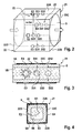
- the Fig. 2 to 4 show the measuring device 21 in an enlarged schematic representation. It concerns a measuring arrangement, which in the WO 2004/057313 A1 is described in detail.
- the measuring arrangement 21 has for this purpose a clamping device 22 with four mutually perpendicular, planar contact surfaces 22A, 22B, 22C, 22D, between which the hose 5 can be clamped.
- the clamping device 22 is dimensioned such that the hose line 5 can deform so that it has a preferably plane outer and inner surface 5A, 5B.
- the measuring arrangement 21 has a transmitter 23 for transmitting electromagnetic radiation, which in particular comprises a plurality of light sources E1, E2, E3, E4, and a receiver 25 for electromagnetic radiation, in particular a plurality of light detectors D11, D21, D31, D41, D12 , D22, D32, D42.
- the light sources together with the light detectors form a measuring device for a transmission measurement, a measuring device for a scattered light measurement and a measuring device for a reflection measurement.
- the clamping device 22 has on the upper side and the lower side as well as on the longitudinal sides in each case a row of three holes arranged at constant distances from one another, in which the light sources and light detectors are respectively arranged.
- the light sources E1, E2, E3, E4, in particular LEDs are after FIG. 2 arranged in the respective first direction in the flow direction, while the light detectors D11, D12, D21, D22, D31, D32, D41, D42, in particular photodiodes, are arranged in the respective second and third bores in the flow direction. It is also possible to exchange the position of the light sources and the light detectors relative to the direction of flow.
- an artificial blood kinetics is generated in the blood-filled tubing at the measuring point.
- the central control and computing unit 17 controls the blood pump 6 such that the blood pump is stopped for a short time interval, in particular for 10 seconds. Subsequently, the blood pump is put back into operation. This maximizes blood kinetics, resulting in an improved signal-to-noise ratio.
- the red blood cells reorient themselves after the disappearance of gravity by stopping the blood pump and sediment predominantly.
- An alternative embodiment provides for changing the blood kinetics that the central control and computing unit 17 controls the blood pump 6 such that the delivery rate of the blood pump for a short first time interval, for example, from 250 ml / min is increased to 400 ml / min and then for a short second time interval, for example is reduced to 100 ml / min, in which case the original delivery rate is set again.
- a further alternative embodiment provides only a drastic reduction of the delivery rate of the blood pump instead of a complete stop of the blood pump 6.
- the delivery rate of the blood pump will be reduced from 250 ml / min to at least 100 ml / min.
- this embodiment results in a poorer signal-to-noise ratio than a complete pump stop.
- the central control and processing unit 17 controls the blood pump 6 and the electromagnetically operable tube clamp 18 such that for a given short time interval the blood pump 6 stops and the tube clamp 18 then in the predetermined short time interval preferably completely or at least partially closed.
- the flow conditions at the measuring point in the section of the arterial blood line 5 upstream of the hose clamp 18 are changed.
- the blood pump 6 is set in motion again and the hose clamp 18 is opened again.
- the closing or opening of the hose clamp can take place continuously during the measurement with the blood pump 6 stopped, ie after stopping the blood pump, the hose clamp is closed at time t 1n and at time t 2n the clamp is opened, etc.
- the measuring arrangement carries out the measurements described below, while the blood kinetics are artificially changed according to one of the methods described above
- S FS . BS .
- SS y dS ⁇ ⁇ 1 t dt / dS ⁇ ⁇ 2 t dt .
- S FS . BS .
- SS ⁇ z / S ⁇ ⁇ 1 t FS ⁇ ⁇ 1 t / S ⁇ ⁇ 2 t FS ⁇ ⁇ 2 t .
- S BS . SS
- hemoglobin in dialysis patients may change due to ultrafiltration during dialysis treatment.
- changes in hemoglobin up to 20% have a relatively large influence on the accuracy of the glucose measurement. Therefore, the device according to the invention for glucose measurement provides for a corresponding compensation.
- hemoglobin is preferably measured continuously.
- the measurement of hemoglobin can be carried out with the same measuring arrangement 21 as the glucose measurement.
- the measurement of the hemoglobin C HB (t) takes place on the basis of the measurement of the 90 ° lateral scattering at a specific wavelength, wherein the blood kinetics is not changed.
- C HB t f SS t t ⁇ t 1 t 2 ,
- the glucose value determined by the method described above is compensated depending on the hemoglobin.
- corresponding correction factors are provided which have been determined empirically and are stored in a memory of the analysis unit 24.
- the measurements were carried out with the above-described measuring arrangement 21, which originates from the WO 2004/057313 A1 is known, carried out in laboratory experiments with bovine blood, which was heated to 37 ° C.
- the artificial change in the blood kinetics at the measuring point was generated by a brief stop of the blood pump 6.
- the glucose content can be determined from the determined intermediate variables on the basis of an empirically made assignment.
- the glucose concentration of human donated blood is artificially defined changed.
- the determined intermediate sizes are then assigned to the known glucose content.
- the obtained mapping of the intermediate values to the glucose content can be stored as a function in a memory of the analysis unit 24 in order to be able to calculate the glucose content later after each measurement. For this, a linear equation is generally sufficient.
- each device for glucose measurement can also be individually calibrated at the factory by measuring a reference pattern with defined properties.
- human blood but also a replacement liquid, in particular cattle blood can be used.
- Fig. 5 shows the measured with the measuring device 21 in a transmission measurement waveform when the blood pump 6 is stopped. It turns out that the signal suddenly decreases after stopping the blood pump.
- the amount of the signal shortly before the stop of the blood pump, for example in the time interval t 1 , and immediately after the stop of the pump, for example in the time interval t 2 is evaluated by the analysis unit 24 for determining the intermediate variable.
- the intermediate variable was calculated according to equation (1) from the amount of the signal shortly before the stop of the blood pump in the time interval t 1 , and immediately after the stop of the pump in the time interval t 2 .
- the blood pump was stopped at a blood flow of 300 ml / min.
- the intermediate variable was calculated according to equation (1) from the amount of the signal shortly before the stop of the blood pump in the time interval t 1 , and immediately after the stop of the pump in the time interval t 2 .
- the blood pump was stopped at a blood flow of 300 ml / min.
- the blood pump was stopped at a blood flow of 200 ml / min.
- the correlation coefficient is 0.9713.
- the blood pump was stopped again at a blood flow of 200 ml / min.
- the correlation coefficient is 0.9927.
- the determination of the glucose content can be carried out both with the individual wavelength measurement and the two-wavelength measurement, it being possible with the measurement arrangement to measure the transmission, reflection and / or sideward scattering. It can be seen that the correlation between the intermediate variable and the determinant (glucose concentration) is best when using equation (3). Taking into account the influence of hemoglobin concentration or oxygen saturation, measurement at two different wavelengths is preferred.
Claims (10)
- Dispositif de mesure d'un composant sanguin dans le sang pour un dispositif de traitement extracorporel du sang, qui comprend un dialyseur ou un filtre subdivisé par une membrane semi-perméable en une première chambre et une deuxième chambre et un système de conduite flexible qui comporte une conduite d'acheminement du sang (5) conduisant à la première chambre (3) du dialyseur (1) ou du filtre et une conduite de retour du sang (7) partant de la première chambre du dialyseur ou du filtre et qui comporte des conduites flexibles essentiellement perméables au rayonnement électromagnétique,
dans lequel le dispositif de mesure d'un composant sanguin présente :un agencement de mesure (21) doté de moyens (24) pour envoyer un rayonnement électromagnétique qui entre dans l'une des conduites flexibles du système de conduites flexibles sur un point de mesure, et des moyens (25) pour recevoir un rayonnement électromagnétique qui sort sur le point de mesure de la conduite flexible, l'agencement de mesure fournissant des données de mesure caractéristiques pour l'intensité du rayonnement électromagnétique entrant dans la conduite flexible sur le point de mesure et sortant de la conduite flexible sur le point de mesure,des moyens (6, 18) pour modifier le comportement d'écoulement d'un liquide s'écoulant sur le point de mesure dans la conduite flexible,des moyens (24) pour analyser les données de mesure obtenues pendant la modification du comportement d'écoulement de l'agencement de mesure (21) et pour déterminer la concentration du composant sanguin à partir des données de mesure,caractérisé en ce queles moyens (6, 18) pour modifier le comportement d'écoulement présentent une pompe de sanguine (6) disposée dans la conduite d'acheminement du sang (5) ou dans la conduite de retour du sang (7) pour transporter le sang, un organe de blocage (18) disposé dans la conduite d'acheminement du sang (5) ou dans la conduite de retour du sang (7) et des moyens (17) pour commander la pompe de sanguine et l'organe de blocage qui sont conçus de telle sorte que le débit de sang dans la conduite d'acheminement du sang ou dans la conduite de retour du sang soit modifié, l'agencement de mesure (21) étant disposé sur la conduite d'acheminement du sang ou la conduite de retour du sang, eten ce que les moyens (17) pour commander la pompe de sanguine (6) et l'organe de blocage (18) sont conçus de telle sorte que la pompe de sanguine (6) soit arrêtée pendant un intervalle de temps prédéterminé et qu'après l'arrêt de la pompe de sanguine, l'organe de blocage (18) soit fermé au moins partiellement, en particulier complètement, puis soit à nouveau ouvert. - Dispositif selon la revendication 1, caractérisé en ce que les moyens (6, 18) pour modifier le comportement d'écoulement du sang s'écoulant dans la conduite d'acheminement de sang ou la conduite de retour du sang présentent une pompe de sanguine (6) disposée dans la conduite d'acheminement du sang (5) pour transporter le sang et un organe de blocage (18) disposé dans la conduite d'acheminement du sang (5).
- Dispositif selon la revendication 1 ou 2, caractérisé en ce que les moyens (17) pour commander la pompe de sanguine (6) et l'organe de blocage (18) sont conçus de telle sorte qu'après l'arrêt de la pompe de sanguine (6), l'organe de blocage (18) est plusieurs fois au moins partiellement fermé et au moins partiellement ouvert.
- Dispositif selon l'une des revendications 1 à 3, caractérisé en ce que l'organe de blocage est un collier de serrage (18) disposé sur la conduite d'acheminement du sang (5).
- Dispositif selon l'une des revendications 1 à 4, caractérisé en ce que les moyens (25A) pour émettre un rayonnement électromagnétique sont conçus comme des moyens pour émettre un rayonnement électromagnétique avec une première longueur d'ondes et une deuxième longueur d'ondes qui se distinguent l'une de l'autre.
- Dispositif selon l'une des revendications 1 à 5, caractérisé en ce que les moyens (25A) pour émettre un rayonnement électromagnétique sont conçus comme des moyens pour émettre un rayonnement électromagnétique à partir de directions différentes qui sont orthogonales les unes par rapport aux autres.
- Dispositif selon l'une des revendications 1 à 6, caractérisé en ce que les moyens (25B) pour recevoir un rayonnement électromagnétique sont conçus comme des moyens pour recevoir un rayonnement électromagnétique à partir de directions différentes qui sont orthogonales les unes par rapport aux autres.
- Dispositif selon l'une des revendications 1 à 7, caractérisé en ce que le rayonnement électromagnétique est une lumière ayant une longueur d'ondes entre 385 nm et 950 nm.
- Dispositif selon l'une des revendications 1 à 8, caractérisé en ce que le composant sanguin est le glucose.
- Dispositif pour le traitement extracorporel du sang, qui comprend un dialyseur (1) ou un filtre subdivisé par une membrane semi-perméable (2) en une première chambre (3) et une deuxième chambre (4) et un système de conduite flexible (I, II) qui présente des conduites flexibles (5, 7 ; 10, 11) perméables au rayonnement électromagnétique, avec un dispositif de mesure d'un composant sanguin selon l'une des revendications 1 à 9.
Applications Claiming Priority (2)
| Application Number | Priority Date | Filing Date | Title |
|---|---|---|---|
| DE102009017304A DE102009017304A1 (de) | 2009-04-11 | 2009-04-11 | Vorrichtung und Verfahren zur Messung eines Blutbestandteils im Blut für eine extrakorporale Blutbehandlungsvorrichtung |
| PCT/EP2010/002188 WO2010115621A2 (fr) | 2009-04-11 | 2010-04-08 | Dispositif et procédé de mesure d'un composant sanguin dans le sang pour un dispositif extracorporel de traitement du sang |
Publications (2)
| Publication Number | Publication Date |
|---|---|
| EP2416699A2 EP2416699A2 (fr) | 2012-02-15 |
| EP2416699B1 true EP2416699B1 (fr) | 2014-03-26 |
Family
ID=42717354
Family Applications (1)
| Application Number | Title | Priority Date | Filing Date |
|---|---|---|---|
| EP10722927.0A Active EP2416699B1 (fr) | 2009-04-11 | 2010-04-08 | Dispositif et procédé de mesure d'un composant sanguin dans le sang pour un dispositif extracorporel de traitement du sang |
Country Status (6)
| Country | Link |
|---|---|
| US (1) | US9265872B2 (fr) |
| EP (1) | EP2416699B1 (fr) |
| JP (1) | JP5536192B2 (fr) |
| CN (1) | CN102387739B (fr) |
| DE (1) | DE102009017304A1 (fr) |
| WO (1) | WO2010115621A2 (fr) |
Families Citing this family (11)
| Publication number | Priority date | Publication date | Assignee | Title |
|---|---|---|---|---|
| DE102010034626A1 (de) * | 2010-08-17 | 2012-02-23 | B. Braun Avitum Ag | Vorrichtung zur extrakorporalen Blutbehandlung |
| DE102011119824B4 (de) | 2011-12-01 | 2013-07-04 | Fresenius Medical Care Deutschland Gmbh | Verfahren und Vorrichtung zur Bestimmung eines Blutbestandteils |
| US8834401B2 (en) * | 2012-11-26 | 2014-09-16 | Becton, Dickinson And Company | Glucose management and dialysis method and apparatus |
| DE102013107010A1 (de) * | 2013-07-03 | 2015-01-22 | Thyssenkrupp Steel Europe Ag | Anlage und Verfahren zum Warmwalzen von Stahlband |
| CN205209954U (zh) * | 2015-11-28 | 2016-05-04 | 深圳市前海安测信息技术有限公司 | 血糖数据采集设备 |
| WO2018078727A1 (fr) * | 2016-10-25 | 2018-05-03 | パイオニア株式会社 | Dispositif de mesure de fluide |
| US10576196B2 (en) | 2017-04-10 | 2020-03-03 | Fresenius Medical Care Holdings, Inc. | Optical detection of air bubbles in either saline or blood or a mixture of both |
| JP6858875B2 (ja) * | 2017-09-29 | 2021-04-14 | パイオニア株式会社 | 計測装置、計測方法、コンピュータプログラム及び記憶媒体 |
| CN111110939A (zh) * | 2018-11-01 | 2020-05-08 | 李韦辰 | 血液分析模块及其血液收集装置 |
| JP7443934B2 (ja) | 2020-05-28 | 2024-03-06 | 株式会社ジェイ・エム・エス | 血液成分測定装置及び血液浄化装置 |
| CN112274128B (zh) * | 2020-12-23 | 2021-04-02 | 广州富玛医药科技股份有限公司 | 一种血液流动测量装置 |
Family Cites Families (16)
| Publication number | Priority date | Publication date | Assignee | Title |
|---|---|---|---|---|
| US5351686A (en) * | 1990-10-06 | 1994-10-04 | In-Line Diagnostics Corporation | Disposable extracorporeal conduit for blood constituent monitoring |
| US5312550B1 (en) * | 1992-04-27 | 1996-04-23 | Robert L Hester | Method for detecting undesired dialysis recirculation |
| JPH06261938A (ja) * | 1992-07-07 | 1994-09-20 | Senko Ika Kogyo Kk | 透析装置及び返血方法 |
| US6222189B1 (en) * | 1992-07-15 | 2001-04-24 | Optix, Lp | Methods of enhancing optical signals by mechanical manipulation in non-invasive testing |
| FR2767478B1 (fr) * | 1997-08-21 | 1999-10-01 | Hospal Ind | Dispositif et procede pour regler la concentration du sodium dans un liquide de dialyse en vue d'une prescription |
| US6041246A (en) * | 1997-10-14 | 2000-03-21 | Transonic Systems, Inc. | Single light sensor optical probe for monitoring blood parameters and cardiovascular measurements |
| SE525639C2 (sv) | 1998-06-04 | 2005-03-22 | Thore Falkvall | Bestämning av slaggprodukter i dialysvätska med hjälp av optisk sensor |
| DE19911265C2 (de) * | 1999-03-13 | 2001-12-13 | Glukomeditech Ag | Vorrichtung zur Messung der Glukosekonzentration proteinhaltiger wässriger Lösungen insbesondere in interstitiellen Gewebsflüssigkeiten,vorzugsweise in implantierbarer mikro-opto-elektronischer Form |
| US6587704B1 (en) * | 1999-06-16 | 2003-07-01 | Orsense Ltd. | Method for non-invasive optical measurements of blood parameters |
| JP3958733B2 (ja) * | 2002-11-14 | 2007-08-15 | 日機装株式会社 | 血液浄化装置 |
| AU2003291591A1 (en) * | 2002-12-20 | 2004-07-14 | Optoq Ab | Method and device for measurements in blood |
| WO2004105596A1 (fr) | 2003-06-03 | 2004-12-09 | Orsense Ltd. | Procede et systeme destines a etre utilises dans des mesures optiques non invasives de parametres sanguins |
| US7313425B2 (en) | 2004-07-08 | 2007-12-25 | Orsense Ltd. | Device and method for non-invasive optical measurements |
| US7254432B2 (en) | 2005-08-17 | 2007-08-07 | Orsense Ltd. | Method and device for non-invasive measurements of blood parameters |
| JP4925159B2 (ja) * | 2005-10-12 | 2012-04-25 | 日機装株式会社 | 血液浄化装置 |
| CN101466419B (zh) | 2006-06-08 | 2012-07-04 | 弗雷泽纽斯医疗保健德国有限公司 | 用于控制体外血液处理设备的装置和方法 |
-
2009
- 2009-04-11 DE DE102009017304A patent/DE102009017304A1/de not_active Withdrawn
-
2010
- 2010-04-08 WO PCT/EP2010/002188 patent/WO2010115621A2/fr active Application Filing
- 2010-04-08 CN CN201080016171.3A patent/CN102387739B/zh active Active
- 2010-04-08 US US13/263,450 patent/US9265872B2/en active Active
- 2010-04-08 JP JP2012503921A patent/JP5536192B2/ja active Active
- 2010-04-08 EP EP10722927.0A patent/EP2416699B1/fr active Active
Also Published As
| Publication number | Publication date |
|---|---|
| JP2012523254A (ja) | 2012-10-04 |
| US20120031841A1 (en) | 2012-02-09 |
| WO2010115621A2 (fr) | 2010-10-14 |
| JP5536192B2 (ja) | 2014-07-02 |
| WO2010115621A3 (fr) | 2010-12-23 |
| DE102009017304A1 (de) | 2010-10-21 |
| EP2416699A2 (fr) | 2012-02-15 |
| US9265872B2 (en) | 2016-02-23 |
| CN102387739B (zh) | 2015-02-18 |
| CN102387739A (zh) | 2012-03-21 |
Similar Documents
| Publication | Publication Date | Title |
|---|---|---|
| EP2416699B1 (fr) | Dispositif et procédé de mesure d'un composant sanguin dans le sang pour un dispositif extracorporel de traitement du sang | |
| EP0911043B1 (fr) | Dispositif pour déterminer des paramètres de performance de modules d'échangeurs de substances et d'énergie | |
| EP2640439B1 (fr) | Dispositif pour atteindre le mieux possible l'objectif de substitution lors de l'ultrafiltration du sang | |
| EP0763367B1 (fr) | Méthode pour tester au moins un filtre monté dans un circuit de dialyse | |
| EP2627368B1 (fr) | Procédé et dispositif pour mesurer et éliminer des variations du système dans un dispositif de traitement du sang | |
| EP0900094B1 (fr) | Dispositif de surveillance de la recirculation pendant un traitement extracorporel du sang | |
| DE10049900C1 (de) | Verfahren zur Bestimmung des Intraperitonealvolumens und Vorrichtung zur Peritonealdialyse | |
| EP2714128B1 (fr) | Dispositif et procédé pour la détection d'un état de fonctionnement d'un traitement de sang extracorporel | |
| EP2783715B1 (fr) | Procédé de détection d'une recirculation dans un shunt artérioveineux pendant une hémodialyse et système de dialyse | |
| DE102011119824B4 (de) | Verfahren und Vorrichtung zur Bestimmung eines Blutbestandteils | |
| WO2012022304A1 (fr) | Dispositif de traitement extracorporel du sang | |
| EP3431118B1 (fr) | Dispositif pour la mise en oeuvre d'une dialyse isonatrique | |
| WO2018109071A1 (fr) | Dispositif de traitement de sang destiné à effectuer un traitement de sang extracorporel, dispositif de conduite de sang, système de traitement de sang | |
| DE60029754T2 (de) | Vorrichtung zur bestimmung des blutwiederumlaufes in einer vaskulären zugangseinrichtung | |
| EP3177336B1 (fr) | Dispositif et procédé servant à déterminer un flux optimal de dialysat en vue d'un traitement du sang extracorporel à l'aide d'un dispositif de traitement du sang extracorporel | |
| EP3955988B1 (fr) | Mesure de recirculation au moyen d'un équilibre de diffusion | |
| EP2783716B1 (fr) | Procédé et dispositif de détection d'une recirculation dans un shunt | |
| EP2696911B1 (fr) | Procédé et dispositif destinés à adapter la performance d'épuration dans le domaine des tailles moléculaires intermédiaires en ajustant le flux de substitution | |
| EP2783713A1 (fr) | Détection de recirculation par bolus | |
| DE3600227A1 (de) | Ultrafiltrationsregeleinrichtung | |
| DE102021126681A1 (de) | Verfahren und Vorrichtung zur Überwachung einer Blutreinigung mit einer extrakorporalen Blutreinigungsvorrichtung | |
| DE8027285U1 (de) | Vorrichtung zur steuerung des fluessigkeitsentzugs bei der haemodialyse |
Legal Events
| Date | Code | Title | Description |
|---|---|---|---|
| PUAI | Public reference made under article 153(3) epc to a published international application that has entered the european phase |
Free format text: ORIGINAL CODE: 0009012 |
|
| 17P | Request for examination filed |
Effective date: 20111110 |
|
| AK | Designated contracting states |
Kind code of ref document: A2 Designated state(s): AT BE BG CH CY CZ DE DK EE ES FI FR GB GR HR HU IE IS IT LI LT LU LV MC MK MT NL NO PL PT RO SE SI SK SM TR |
|
| DAX | Request for extension of the european patent (deleted) | ||
| GRAP | Despatch of communication of intention to grant a patent |
Free format text: ORIGINAL CODE: EPIDOSNIGR1 |
|
| INTG | Intention to grant announced |
Effective date: 20131121 |
|
| GRAS | Grant fee paid |
Free format text: ORIGINAL CODE: EPIDOSNIGR3 |
|
| GRAA | (expected) grant |
Free format text: ORIGINAL CODE: 0009210 |
|
| AK | Designated contracting states |
Kind code of ref document: B1 Designated state(s): AT BE BG CH CY CZ DE DK EE ES FI FR GB GR HR HU IE IS IT LI LT LU LV MC MK MT NL NO PL PT RO SE SI SK SM TR |
|
| REG | Reference to a national code |
Ref country code: GB Ref legal event code: FG4D Free format text: NOT ENGLISH |
|
| REG | Reference to a national code |
Ref country code: CH Ref legal event code: EP |
|
| REG | Reference to a national code |
Ref country code: AT Ref legal event code: REF Ref document number: 658495 Country of ref document: AT Kind code of ref document: T Effective date: 20140415 |
|
| REG | Reference to a national code |
Ref country code: IE Ref legal event code: FG4D Free format text: LANGUAGE OF EP DOCUMENT: GERMAN |
|
| REG | Reference to a national code |
Ref country code: DE Ref legal event code: R096 Ref document number: 502010006482 Country of ref document: DE Effective date: 20140508 |
|
| REG | Reference to a national code |
Ref country code: SE Ref legal event code: TRGR |
|
| PG25 | Lapsed in a contracting state [announced via postgrant information from national office to epo] |
Ref country code: NO Free format text: LAPSE BECAUSE OF FAILURE TO SUBMIT A TRANSLATION OF THE DESCRIPTION OR TO PAY THE FEE WITHIN THE PRESCRIBED TIME-LIMIT Effective date: 20140626 Ref country code: LT Free format text: LAPSE BECAUSE OF FAILURE TO SUBMIT A TRANSLATION OF THE DESCRIPTION OR TO PAY THE FEE WITHIN THE PRESCRIBED TIME-LIMIT Effective date: 20140326 |
|
| REG | Reference to a national code |
Ref country code: NL Ref legal event code: VDEP Effective date: 20140326 |
|
| REG | Reference to a national code |
Ref country code: LT Ref legal event code: MG4D |
|
| PG25 | Lapsed in a contracting state [announced via postgrant information from national office to epo] |
Ref country code: FI Free format text: LAPSE BECAUSE OF FAILURE TO SUBMIT A TRANSLATION OF THE DESCRIPTION OR TO PAY THE FEE WITHIN THE PRESCRIBED TIME-LIMIT Effective date: 20140326 |
|
| PG25 | Lapsed in a contracting state [announced via postgrant information from national office to epo] |
Ref country code: LV Free format text: LAPSE BECAUSE OF FAILURE TO SUBMIT A TRANSLATION OF THE DESCRIPTION OR TO PAY THE FEE WITHIN THE PRESCRIBED TIME-LIMIT Effective date: 20140326 Ref country code: HR Free format text: LAPSE BECAUSE OF FAILURE TO SUBMIT A TRANSLATION OF THE DESCRIPTION OR TO PAY THE FEE WITHIN THE PRESCRIBED TIME-LIMIT Effective date: 20140326 |
|
| PG25 | Lapsed in a contracting state [announced via postgrant information from national office to epo] |
Ref country code: CZ Free format text: LAPSE BECAUSE OF FAILURE TO SUBMIT A TRANSLATION OF THE DESCRIPTION OR TO PAY THE FEE WITHIN THE PRESCRIBED TIME-LIMIT Effective date: 20140326 Ref country code: NL Free format text: LAPSE BECAUSE OF FAILURE TO SUBMIT A TRANSLATION OF THE DESCRIPTION OR TO PAY THE FEE WITHIN THE PRESCRIBED TIME-LIMIT Effective date: 20140326 Ref country code: EE Free format text: LAPSE BECAUSE OF FAILURE TO SUBMIT A TRANSLATION OF THE DESCRIPTION OR TO PAY THE FEE WITHIN THE PRESCRIBED TIME-LIMIT Effective date: 20140326 Ref country code: RO Free format text: LAPSE BECAUSE OF FAILURE TO SUBMIT A TRANSLATION OF THE DESCRIPTION OR TO PAY THE FEE WITHIN THE PRESCRIBED TIME-LIMIT Effective date: 20140326 Ref country code: CY Free format text: LAPSE BECAUSE OF FAILURE TO SUBMIT A TRANSLATION OF THE DESCRIPTION OR TO PAY THE FEE WITHIN THE PRESCRIBED TIME-LIMIT Effective date: 20140326 Ref country code: IS Free format text: LAPSE BECAUSE OF FAILURE TO SUBMIT A TRANSLATION OF THE DESCRIPTION OR TO PAY THE FEE WITHIN THE PRESCRIBED TIME-LIMIT Effective date: 20140726 Ref country code: BG Free format text: LAPSE BECAUSE OF FAILURE TO SUBMIT A TRANSLATION OF THE DESCRIPTION OR TO PAY THE FEE WITHIN THE PRESCRIBED TIME-LIMIT Effective date: 20140626 |
|
| PG25 | Lapsed in a contracting state [announced via postgrant information from national office to epo] |
Ref country code: MC Free format text: LAPSE BECAUSE OF FAILURE TO SUBMIT A TRANSLATION OF THE DESCRIPTION OR TO PAY THE FEE WITHIN THE PRESCRIBED TIME-LIMIT Effective date: 20140326 Ref country code: ES Free format text: LAPSE BECAUSE OF FAILURE TO SUBMIT A TRANSLATION OF THE DESCRIPTION OR TO PAY THE FEE WITHIN THE PRESCRIBED TIME-LIMIT Effective date: 20140326 Ref country code: SK Free format text: LAPSE BECAUSE OF FAILURE TO SUBMIT A TRANSLATION OF THE DESCRIPTION OR TO PAY THE FEE WITHIN THE PRESCRIBED TIME-LIMIT Effective date: 20140326 Ref country code: PL Free format text: LAPSE BECAUSE OF FAILURE TO SUBMIT A TRANSLATION OF THE DESCRIPTION OR TO PAY THE FEE WITHIN THE PRESCRIBED TIME-LIMIT Effective date: 20140326 |
|
| REG | Reference to a national code |
Ref country code: CH Ref legal event code: PL |
|
| PG25 | Lapsed in a contracting state [announced via postgrant information from national office to epo] |
Ref country code: PT Free format text: LAPSE BECAUSE OF FAILURE TO SUBMIT A TRANSLATION OF THE DESCRIPTION OR TO PAY THE FEE WITHIN THE PRESCRIBED TIME-LIMIT Effective date: 20140728 |
|
| REG | Reference to a national code |
Ref country code: DE Ref legal event code: R097 Ref document number: 502010006482 Country of ref document: DE |
|
| REG | Reference to a national code |
Ref country code: IE Ref legal event code: MM4A |
|
| PG25 | Lapsed in a contracting state [announced via postgrant information from national office to epo] |
Ref country code: LI Free format text: LAPSE BECAUSE OF NON-PAYMENT OF DUE FEES Effective date: 20140430 Ref country code: DK Free format text: LAPSE BECAUSE OF FAILURE TO SUBMIT A TRANSLATION OF THE DESCRIPTION OR TO PAY THE FEE WITHIN THE PRESCRIBED TIME-LIMIT Effective date: 20140326 Ref country code: CH Free format text: LAPSE BECAUSE OF NON-PAYMENT OF DUE FEES Effective date: 20140430 |
|
| PLBE | No opposition filed within time limit |
Free format text: ORIGINAL CODE: 0009261 |
|
| STAA | Information on the status of an ep patent application or granted ep patent |
Free format text: STATUS: NO OPPOSITION FILED WITHIN TIME LIMIT |
|
| 26N | No opposition filed |
Effective date: 20150106 |
|
| REG | Reference to a national code |
Ref country code: FR Ref legal event code: PLFP Year of fee payment: 6 |
|
| REG | Reference to a national code |
Ref country code: DE Ref legal event code: R097 Ref document number: 502010006482 Country of ref document: DE Effective date: 20150106 |
|
| PG25 | Lapsed in a contracting state [announced via postgrant information from national office to epo] |
Ref country code: IE Free format text: LAPSE BECAUSE OF NON-PAYMENT OF DUE FEES Effective date: 20140408 |
|
| PG25 | Lapsed in a contracting state [announced via postgrant information from national office to epo] |
Ref country code: SI Free format text: LAPSE BECAUSE OF FAILURE TO SUBMIT A TRANSLATION OF THE DESCRIPTION OR TO PAY THE FEE WITHIN THE PRESCRIBED TIME-LIMIT Effective date: 20140326 |
|
| REG | Reference to a national code |
Ref country code: FR Ref legal event code: PLFP Year of fee payment: 7 |
|
| PG25 | Lapsed in a contracting state [announced via postgrant information from national office to epo] |
Ref country code: MT Free format text: LAPSE BECAUSE OF FAILURE TO SUBMIT A TRANSLATION OF THE DESCRIPTION OR TO PAY THE FEE WITHIN THE PRESCRIBED TIME-LIMIT Effective date: 20140326 |
|
| PG25 | Lapsed in a contracting state [announced via postgrant information from national office to epo] |
Ref country code: SM Free format text: LAPSE BECAUSE OF FAILURE TO SUBMIT A TRANSLATION OF THE DESCRIPTION OR TO PAY THE FEE WITHIN THE PRESCRIBED TIME-LIMIT Effective date: 20140326 |
|
| REG | Reference to a national code |
Ref country code: AT Ref legal event code: MM01 Ref document number: 658495 Country of ref document: AT Kind code of ref document: T Effective date: 20150408 |
|
| PG25 | Lapsed in a contracting state [announced via postgrant information from national office to epo] |
Ref country code: GR Free format text: LAPSE BECAUSE OF FAILURE TO SUBMIT A TRANSLATION OF THE DESCRIPTION OR TO PAY THE FEE WITHIN THE PRESCRIBED TIME-LIMIT Effective date: 20140627 |
|
| PG25 | Lapsed in a contracting state [announced via postgrant information from national office to epo] |
Ref country code: BE Free format text: LAPSE BECAUSE OF FAILURE TO SUBMIT A TRANSLATION OF THE DESCRIPTION OR TO PAY THE FEE WITHIN THE PRESCRIBED TIME-LIMIT Effective date: 20140430 Ref country code: TR Free format text: LAPSE BECAUSE OF FAILURE TO SUBMIT A TRANSLATION OF THE DESCRIPTION OR TO PAY THE FEE WITHIN THE PRESCRIBED TIME-LIMIT Effective date: 20140326 Ref country code: LU Free format text: LAPSE BECAUSE OF NON-PAYMENT OF DUE FEES Effective date: 20140408 Ref country code: HU Free format text: LAPSE BECAUSE OF FAILURE TO SUBMIT A TRANSLATION OF THE DESCRIPTION OR TO PAY THE FEE WITHIN THE PRESCRIBED TIME-LIMIT; INVALID AB INITIO Effective date: 20100408 |
|
| PG25 | Lapsed in a contracting state [announced via postgrant information from national office to epo] |
Ref country code: AT Free format text: LAPSE BECAUSE OF NON-PAYMENT OF DUE FEES Effective date: 20150408 |
|
| REG | Reference to a national code |
Ref country code: FR Ref legal event code: PLFP Year of fee payment: 8 |
|
| REG | Reference to a national code |
Ref country code: FR Ref legal event code: PLFP Year of fee payment: 9 |
|
| PG25 | Lapsed in a contracting state [announced via postgrant information from national office to epo] |
Ref country code: MK Free format text: LAPSE BECAUSE OF FAILURE TO SUBMIT A TRANSLATION OF THE DESCRIPTION OR TO PAY THE FEE WITHIN THE PRESCRIBED TIME-LIMIT Effective date: 20140326 |
|
| PGFP | Annual fee paid to national office [announced via postgrant information from national office to epo] |
Ref country code: FR Payment date: 20230321 Year of fee payment: 14 |
|
| PGFP | Annual fee paid to national office [announced via postgrant information from national office to epo] |
Ref country code: SE Payment date: 20230327 Year of fee payment: 14 Ref country code: IT Payment date: 20230322 Year of fee payment: 14 |
|
| P01 | Opt-out of the competence of the unified patent court (upc) registered |
Effective date: 20230602 |
|
| PGFP | Annual fee paid to national office [announced via postgrant information from national office to epo] |
Ref country code: DE Payment date: 20230321 Year of fee payment: 14 |
|
| PGFP | Annual fee paid to national office [announced via postgrant information from national office to epo] |
Ref country code: GB Payment date: 20240320 Year of fee payment: 15 |