EP2415576A1 - Method of picking up a cast - Google Patents
Method of picking up a cast Download PDFInfo
- Publication number
- EP2415576A1 EP2415576A1 EP11176648A EP11176648A EP2415576A1 EP 2415576 A1 EP2415576 A1 EP 2415576A1 EP 11176648 A EP11176648 A EP 11176648A EP 11176648 A EP11176648 A EP 11176648A EP 2415576 A1 EP2415576 A1 EP 2415576A1
- Authority
- EP
- European Patent Office
- Prior art keywords
- cast
- core
- die
- slope
- undercut portion
- Prior art date
- Legal status (The legal status is an assumption and is not a legal conclusion. Google has not performed a legal analysis and makes no representation as to the accuracy of the status listed.)
- Withdrawn
Links
Images




Classifications
-
- B—PERFORMING OPERATIONS; TRANSPORTING
- B29—WORKING OF PLASTICS; WORKING OF SUBSTANCES IN A PLASTIC STATE IN GENERAL
- B29C—SHAPING OR JOINING OF PLASTICS; SHAPING OF MATERIAL IN A PLASTIC STATE, NOT OTHERWISE PROVIDED FOR; AFTER-TREATMENT OF THE SHAPED PRODUCTS, e.g. REPAIRING
- B29C33/00—Moulds or cores; Details thereof or accessories therefor
- B29C33/44—Moulds or cores; Details thereof or accessories therefor with means for, or specially constructed to facilitate, the removal of articles, e.g. of undercut articles
- B29C33/48—Moulds or cores; Details thereof or accessories therefor with means for, or specially constructed to facilitate, the removal of articles, e.g. of undercut articles with means for collapsing or disassembling
-
- B—PERFORMING OPERATIONS; TRANSPORTING
- B29—WORKING OF PLASTICS; WORKING OF SUBSTANCES IN A PLASTIC STATE IN GENERAL
- B29C—SHAPING OR JOINING OF PLASTICS; SHAPING OF MATERIAL IN A PLASTIC STATE, NOT OTHERWISE PROVIDED FOR; AFTER-TREATMENT OF THE SHAPED PRODUCTS, e.g. REPAIRING
- B29C45/00—Injection moulding, i.e. forcing the required volume of moulding material through a nozzle into a closed mould; Apparatus therefor
- B29C45/17—Component parts, details or accessories; Auxiliary operations
- B29C45/40—Removing or ejecting moulded articles
- B29C45/44—Removing or ejecting moulded articles for undercut articles
- B29C45/4421—Removing or ejecting moulded articles for undercut articles using expansible or collapsible cores
-
- B—PERFORMING OPERATIONS; TRANSPORTING
- B29—WORKING OF PLASTICS; WORKING OF SUBSTANCES IN A PLASTIC STATE IN GENERAL
- B29C—SHAPING OR JOINING OF PLASTICS; SHAPING OF MATERIAL IN A PLASTIC STATE, NOT OTHERWISE PROVIDED FOR; AFTER-TREATMENT OF THE SHAPED PRODUCTS, e.g. REPAIRING
- B29C45/00—Injection moulding, i.e. forcing the required volume of moulding material through a nozzle into a closed mould; Apparatus therefor
- B29C45/17—Component parts, details or accessories; Auxiliary operations
- B29C45/26—Moulds
- B29C45/33—Moulds having transversely, e.g. radially, movable mould parts
-
- B—PERFORMING OPERATIONS; TRANSPORTING
- B29—WORKING OF PLASTICS; WORKING OF SUBSTANCES IN A PLASTIC STATE IN GENERAL
- B29L—INDEXING SCHEME ASSOCIATED WITH SUBCLASS B29C, RELATING TO PARTICULAR ARTICLES
- B29L2031/00—Other particular articles
- B29L2031/30—Vehicles, e.g. ships or aircraft, or body parts thereof
Definitions
- FIG. 2 An injection mold apparatus to mold such a cast 1 is shown in FIG. 2 , and in FIG. 2(b) the upper die 4 is omitted.
Landscapes
- Engineering & Computer Science (AREA)
- Mechanical Engineering (AREA)
- Manufacturing & Machinery (AREA)
- Moulds For Moulding Plastics Or The Like (AREA)
- Molds, Cores, And Manufacturing Methods Thereof (AREA)
Abstract
A process to detach an upper die (5) from a lower die (4).
A process to detach a right and left outside slide core (6a, 6b) from a cast (1) after the above process.
A process to bring close to each other and push up a right and left slope core (7a, 7c) until the width of both ends of the right and left slope core are shorter than the distance between the ends of the cast (1) after the above process.
A process to separate the slope core (7a, 7c) from the cast (1) by moving the cast (1) after the above process.
Description
- Present invention relates to a method to pick up a cast having an undercut portion from a die.
- It is known as a conventional method to roll up an undercut portion of a cast and then pick up the cast from a die, for example, Japanese Patent Application Publication No.
2007-69507 - However, the invention as described in
Patent Document 1 has a problem; that is the mechanism which rolls up a cast must be provided in the inside of the die. Therefore the structure of the die becomes complicated, and it is necessary to synchronize the pick up device of the cast with the movement of the die. Furthermore, the means is also complicated. - The purpose of the present invention is to solve the above problem and supply a method to pick up a cast without the roll up the cast.
- In order to solve above-mentioned problems, a method to pick up a cast from a die, the shape of the cast is channel like and has a tail part provided on the undercut portion and a side part (with right and left sections) is provided on the undercut portion, the undercut portion extends to the right and left portion of the tail part, comprising:
- A process to separate an upper die from a lower die.
- A process to separate a right and left outside slide core from a cast following the above process.
- A process to bring close to each other and push up a right and left slope core until the width of both ends of the right and left slope core becomes shorter than the distance between the ends of the cast after the above process. The slope core is divided into a right and left section to mold an undercut portion respectively.
- A process to separate the slope core from the cast by moving the cast after the above process.
- A process to separate a straight push core from the cast after, or at the same time as, the above process.
- The present invention makes it possible to pick up a cast having an undercut portion from a die without rolling up an undercut portion, Therefore it prevents a cast from causing elastic deformation just after forming and thus, an improvement in the quality can be expected.
-
-
FIG. 1 is an illustration of a cast, (a) is a plane view, (b) is a back view. -
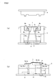
FIG. 2 is an illustration of a molding apparatus, (a) is a sectional view, (b) is a side view. -
FIG. 3 is an illustration of a device carrying out a method of the present invention, (a) is a front view, (b) is a side view. -
FIG. 4 is an illustration of a separation process of an upper die, (a) is a front view, (b) is a side view. -
FIG. 5 is an illustration of a separation process of an outside slide core, (a) is a front view, (b) is a side view. -
FIG. 6 is an illustration of a bringing close to each other and pushing up process of a slope core, (a) is a front view, (b) is a side view. -
FIG. 7 is an illustration of the width of both ends of the right and left slope core and the distance between the ends of the cast. -
FIG. 8 is an illustration of a separation process of an outside slide core, (a) is a front view, (b) is a side view. -
FIG. 9 is an illustration of a separation process of a straight push core, (a) is a front view, (b) is a side view. - Embodiment of the invention is explained to the attached drawings. As shown in
Fig 1 , for example, thecast 1 which is the object of the method of the present invention is a rear cowl of a motorcycle. The shape of the rear cowl is channel like and has atail part 2 providedundercut portion 2a and aside part 3 of one pair of right and left providedundercut portion undercut portion tail part 2. - An injection mold apparatus to mold such a
cast 1 is shown inFIG. 2 , and inFIG. 2(b) theupper die 4 is omitted. - The injection mold apparatus is comprised of an
upper die 4, alower die 5, right and left outsideslide core slope core undercut portion side part 3, and astraight push core 8 which molds theundercut portion 2a of thetail part 2. - The
slope core rod first push plate 9 placed below thelower die 5, thefirst push plate 9 performs elevation by a drive means not-shown, and theslope core first push plate 9 and make a diagonal elevation. Then theleft slope core right slope core - Also, the
second push plate 11 is disposed between thelower die 5 and thefirst push plate 9, and astraight push rod 12 is connected to thesecond push plate 11, thestraight push rod 12 performs the elevation of thestraight push core 8. - The
first push plate 9 and thesecond push plate 11 perform elevation by two steppedhydraulic cylinders 13, and the stroke of thesecond push plate 11 is set to be longer than - The device which picks up the
cast 1 from a die after forming is shown inFig 3 , this device includes an adsorption means 15 to adsorb thecast 1 after the mold release, a movingmeans 16 to move the adsorption means 15 that has adsorbed thecast 1 in the arrow A direction. - As for the adsorption means 15, three suction cups are provided in total, one suction cup adsorbs the
tail section 2 ofcast 1, and the other two suction cups adsorb theside part 3. - And when the
second push plate 11 rises by being driven by the drive of the two steppedhydraulic cylinder 13, thestraight push rod 12 connected with thesecond push plate 11 rises, and thestraight push core 8 is pushed up. Then thecast 1 abuts with adsorption means 15, and is adsorbed. - A pick up method of the present invention, using the apparatus which is comprised as above, is explained below.
- At first, as shown in
FIG. 4 , after molding, theupper die 4 rises and theupper die 4 detaches from thelower die 5, and the opening of the die is completed. (upper die separation process). - And, as shown in
FIG. 5 , the right andleft slide core left slide core - Then, as shown in
FIG. 6 , the right andleft slope core left slope core - At this time, as shown in
FIG. 7 , the width W1 of the right andleft slope core undercut portion left slope core undercut portion - So that it can make the
slope core cast 1 in the next process. - As shown in
FIG. 8 , thesecond push plate 11 rises by the drive of two steppedhydraulic cylinder 13, and thestraight push rod 12 rises, then thestraight push rod 12 pushes up thetail part 2 and goes through thestraight push core 8, theslope core cast 1. (slope core separating process). - And, the
cast 1 abuts with three adsorption means (suction cups) 15 and is adsorbed, the three adsorption means are located so as to adsorb at one place on thetail part 2 and at two places on theside part 3. - In the process to separate the slope core, depending on the shape of the
cast 1, it is possible to pick up thecast 1 from theslope core cast 1 horizontally without pushing up thestraight push core 8. - Also, as a means to move
cast 1, it is conceivable that a gripping means, clamping means or support means can be applied as an alternative to the adsorption means 15. - Then, as shown in
FIG. 9 , by moving the moving means 16 in the arrow B direction, theundercut portion 2a of thetail part 2 detaches from thestraight push core 8 smoothly. (straight push core separation process). and thecast 1 is completely released from the die. - The work to pick up the
cast 1 having anundercut portion FIG. 2 (a) . - In the process to separate the slope core, when picking up the
cast 1 from theslope core cast 1 horizontally without pushing up thestraight push core 8 then theslope core straight push core 8 are carried out at the same time, and theslope core straight push core 8 detach from thecast 1 at the same time. - In the above embodiment, the die 4, 5 are installed so that a mold release direction becomes vertical, However, the
die means 16 are turned through 90 degrees, so that the mold release direction becomes horizontal. - The present invention makes it possible to pick up a cast having an undercut portion from a die without rolling up an undercut portion.
- 1... cast, 2... tail part, 2a, 3 a, 3b...undercut portion, 3 ... side part, 4 ... die, 5...die, 6a, 6b ... outside slide core, 7 a, 7b, 7c, 7d ... slope core, 8...straight push core, 9... first push plate, 10 a, 10b, 10c, 10d...rod, 11...second push plate, 12...straight push rod, 13...two stepped hydraulic cylinder, 15... adsorption means, 16... moving means
Claims (1)
- A method to pick up a cast (1) from a die, the shape of the cast (1) is channel like and has a tail part provided on the undercut portion and a side part with right and left sections is provided on the undercut portion, the undercut portion extends to the right and left portion of the tail part,
comprising:a process to separate an upper die (5) from a lower die (4),a process to detach a right and left outside slide core from a cast (1) after the above process,a process to bring closer together and push up a right and left slope core (7a, 7c) until the width of both ends of the right and left slope core (7a, 7c) are shorter than the distance between the ends of the cast (1) after the above process. The slope core (7a, 7c) is divided into a right and left section to mold an undercut portion respectively,a process to separate the slope core (7a, 7c) from the cast (1) by moving the cast (1) after the above process,a process to separate a straight push core from the cast (1) after the above process or at the same time.
Applications Claiming Priority (1)
| Application Number | Priority Date | Filing Date | Title |
|---|---|---|---|
| JP2010175924A JP5553706B2 (en) | 2010-08-05 | 2010-08-05 | How to take out the molded product |
Publications (1)
| Publication Number | Publication Date |
|---|---|
| EP2415576A1 true EP2415576A1 (en) | 2012-02-08 |
Family
ID=44785200
Family Applications (1)
| Application Number | Title | Priority Date | Filing Date |
|---|---|---|---|
| EP11176648A Withdrawn EP2415576A1 (en) | 2010-08-05 | 2011-08-05 | Method of picking up a cast |
Country Status (3)
| Country | Link |
|---|---|
| EP (1) | EP2415576A1 (en) |
| JP (1) | JP5553706B2 (en) |
| BR (1) | BRPI1104051A2 (en) |
Cited By (3)
| Publication number | Priority date | Publication date | Assignee | Title |
|---|---|---|---|---|
| FR3020588A1 (en) * | 2014-04-30 | 2015-11-06 | Faurecia Interieur Ind | PROCESS FOR PRODUCING AN INTERNAL STRUCTURE, CORRESPONDING MANUFACTURING ASSEMBLY, INTERNAL STRUCTURE MANUFACTURED ACCORDING TO THE METHOD |
| CN105313283A (en) * | 2014-06-05 | 2016-02-10 | 罗伯特·博世有限公司 | Die and method for making gear with sphere teeth |
| CN109551718A (en) * | 2018-11-02 | 2019-04-02 | 浙江工商职业技术学院 | A kind of pulled core structure three times of mold |
Citations (8)
| Publication number | Priority date | Publication date | Assignee | Title |
|---|---|---|---|---|
| JPS61135614U (en) * | 1985-02-15 | 1986-08-23 | ||
| US4881891A (en) * | 1989-01-11 | 1989-11-21 | Triangle Tool Corporation | Mold side wall locking apparatus |
| JPH11309760A (en) * | 1998-04-27 | 1999-11-09 | Takagi Seiko Corp | Exterior trim article for bycycle and mold therefor |
| JP2000094479A (en) * | 1998-09-21 | 2000-04-04 | Sharp Corp | Injection molding die and injection molding method |
| FR2809344A1 (en) * | 2000-05-24 | 2001-11-30 | Ecia Equip Composants Ind Auto | Large injection mold for e.g. vehicle bumpers with ejection accompanied by deformation, includes mechanical connections forming cams |
| JP2007069507A (en) | 2005-09-08 | 2007-03-22 | Mazda Motor Corp | Injection molding product manufacturing apparatus and manufacturing method thereof |
| EP2324983A1 (en) * | 2009-11-18 | 2011-05-25 | Honda Motor Co., Ltd. | Method of ejecting molded article, apparatus of the same, and molding apparatus |
| JP2011104876A (en) * | 2009-11-18 | 2011-06-02 | Honda Motor Co Ltd | Apparatus for ejecting molded article and method therefor |
Family Cites Families (3)
| Publication number | Priority date | Publication date | Assignee | Title |
|---|---|---|---|---|
| JPS58134726A (en) * | 1982-02-05 | 1983-08-11 | Nissan Motor Co Ltd | Mold for injection molding |
| JPH0436248Y2 (en) * | 1986-08-08 | 1992-08-27 | ||
| JPH1016014A (en) * | 1996-07-01 | 1998-01-20 | Mazda Motor Corp | Injection molding equipment |
-
2010
- 2010-08-05 JP JP2010175924A patent/JP5553706B2/en not_active Expired - Fee Related
-
2011
- 2011-08-04 BR BRPI1104051 patent/BRPI1104051A2/en not_active Application Discontinuation
- 2011-08-05 EP EP11176648A patent/EP2415576A1/en not_active Withdrawn
Patent Citations (8)
| Publication number | Priority date | Publication date | Assignee | Title |
|---|---|---|---|---|
| JPS61135614U (en) * | 1985-02-15 | 1986-08-23 | ||
| US4881891A (en) * | 1989-01-11 | 1989-11-21 | Triangle Tool Corporation | Mold side wall locking apparatus |
| JPH11309760A (en) * | 1998-04-27 | 1999-11-09 | Takagi Seiko Corp | Exterior trim article for bycycle and mold therefor |
| JP2000094479A (en) * | 1998-09-21 | 2000-04-04 | Sharp Corp | Injection molding die and injection molding method |
| FR2809344A1 (en) * | 2000-05-24 | 2001-11-30 | Ecia Equip Composants Ind Auto | Large injection mold for e.g. vehicle bumpers with ejection accompanied by deformation, includes mechanical connections forming cams |
| JP2007069507A (en) | 2005-09-08 | 2007-03-22 | Mazda Motor Corp | Injection molding product manufacturing apparatus and manufacturing method thereof |
| EP2324983A1 (en) * | 2009-11-18 | 2011-05-25 | Honda Motor Co., Ltd. | Method of ejecting molded article, apparatus of the same, and molding apparatus |
| JP2011104876A (en) * | 2009-11-18 | 2011-06-02 | Honda Motor Co Ltd | Apparatus for ejecting molded article and method therefor |
Cited By (4)
| Publication number | Priority date | Publication date | Assignee | Title |
|---|---|---|---|---|
| FR3020588A1 (en) * | 2014-04-30 | 2015-11-06 | Faurecia Interieur Ind | PROCESS FOR PRODUCING AN INTERNAL STRUCTURE, CORRESPONDING MANUFACTURING ASSEMBLY, INTERNAL STRUCTURE MANUFACTURED ACCORDING TO THE METHOD |
| CN105313283A (en) * | 2014-06-05 | 2016-02-10 | 罗伯特·博世有限公司 | Die and method for making gear with sphere teeth |
| CN105313283B (en) * | 2014-06-05 | 2019-07-12 | 罗伯特·博世有限公司 | For manufacturing the mold and method of the gear with spherical surface teeth portion |
| CN109551718A (en) * | 2018-11-02 | 2019-04-02 | 浙江工商职业技术学院 | A kind of pulled core structure three times of mold |
Also Published As
| Publication number | Publication date |
|---|---|
| JP2012035461A (en) | 2012-02-23 |
| JP5553706B2 (en) | 2014-07-16 |
| BRPI1104051A2 (en) | 2014-02-11 |
Similar Documents
| Publication | Publication Date | Title |
|---|---|---|
| CN103878928A (en) | Clamp for automatically inlaying cylindrical insert in mold | |
| EP2415576A1 (en) | Method of picking up a cast | |
| CN105234232A (en) | Special mould for edge wrapping of automobile trunk door | |
| CN104379227B (en) | Slide fastener assembling device | |
| CN102218485A (en) | Productive technology of rope head taper sleeve for elevator | |
| JP5386315B2 (en) | Molded product take-out device | |
| EP2324983A1 (en) | Method of ejecting molded article, apparatus of the same, and molding apparatus | |
| KR200479478Y1 (en) | device for reducing a pillar diameter of communication cable | |
| KR20120094621A (en) | Link bending system | |
| JP5550915B2 (en) | Mold release method and apparatus | |
| CN104550613B (en) | forging device | |
| KR101580476B1 (en) | Mold clamping device for press | |
| JP6221768B2 (en) | Dummy block handling device for direct extrusion press | |
| CN113172166A (en) | An automobile pipe fitting flaring machine | |
| CN106099030A (en) | The continuous automatic reforming device of accumulator plate | |
| CN207839901U (en) | A stamping device for gear processing equipment | |
| CN114713785B (en) | Light alloy integrated continuous die-casting molding device and method | |
| CN107020346A (en) | A kind of hot press forge device people automatic loading/unloading fixture | |
| CN217474548U (en) | Automatic stamping die frame of material loading unloading | |
| CN104438416B (en) | A kind of stripper apparatus of extrusion die | |
| CN222470669U (en) | A die-casting mold for automobile seat bracket | |
| CN103801595B (en) | A kind of chain U-shaped carrier bar automatic pressing bending apparatus | |
| CN210552450U (en) | Die limiting mechanism | |
| RU2479374C2 (en) | Method of forming complex large-sized part with pneumatic extractors in female die (versions) | |
| CN215786707U (en) | Mechanical separation equipment for castings |
Legal Events
| Date | Code | Title | Description |
|---|---|---|---|
| 17P | Request for examination filed |
Effective date: 20110805 |
|
| AK | Designated contracting states |
Kind code of ref document: A1 Designated state(s): AL AT BE BG CH CY CZ DE DK EE ES FI FR GB GR HR HU IE IS IT LI LT LU LV MC MK MT NL NO PL PT RO RS SE SI SK SM TR |
|
| AX | Request for extension of the european patent |
Extension state: BA ME |
|
| PUAI | Public reference made under article 153(3) epc to a published international application that has entered the european phase |
Free format text: ORIGINAL CODE: 0009012 |
|
| 17Q | First examination report despatched |
Effective date: 20160607 |
|
| STAA | Information on the status of an ep patent application or granted ep patent |
Free format text: STATUS: EXAMINATION IS IN PROGRESS |
|
| STAA | Information on the status of an ep patent application or granted ep patent |
Free format text: STATUS: THE APPLICATION IS DEEMED TO BE WITHDRAWN |
|
| 18D | Application deemed to be withdrawn |
Effective date: 20200303 |