EP2415539A1 - Method for manufacturing torsion beam and torsion beam - Google Patents
Method for manufacturing torsion beam and torsion beam Download PDFInfo
- Publication number
- EP2415539A1 EP2415539A1 EP10758933A EP10758933A EP2415539A1 EP 2415539 A1 EP2415539 A1 EP 2415539A1 EP 10758933 A EP10758933 A EP 10758933A EP 10758933 A EP10758933 A EP 10758933A EP 2415539 A1 EP2415539 A1 EP 2415539A1
- Authority
- EP
- European Patent Office
- Prior art keywords
- tubular body
- bending
- portions
- shape
- tube
- Prior art date
- Legal status (The legal status is an assumption and is not a legal conclusion. Google has not performed a legal analysis and makes no representation as to the accuracy of the status listed.)
- Granted
Links
Images


Classifications
-
- B—PERFORMING OPERATIONS; TRANSPORTING
- B21—MECHANICAL METAL-WORKING WITHOUT ESSENTIALLY REMOVING MATERIAL; PUNCHING METAL
- B21D—WORKING OR PROCESSING OF SHEET METAL OR METAL TUBES, RODS OR PROFILES WITHOUT ESSENTIALLY REMOVING MATERIAL; PUNCHING METAL
- B21D53/00—Making other particular articles
- B21D53/88—Making other particular articles other parts for vehicles, e.g. cowlings, mudguards
-
- B—PERFORMING OPERATIONS; TRANSPORTING
- B21—MECHANICAL METAL-WORKING WITHOUT ESSENTIALLY REMOVING MATERIAL; PUNCHING METAL
- B21D—WORKING OR PROCESSING OF SHEET METAL OR METAL TUBES, RODS OR PROFILES WITHOUT ESSENTIALLY REMOVING MATERIAL; PUNCHING METAL
- B21D11/00—Bending not restricted to forms of material mentioned in only one of groups B21D5/00, B21D7/00, B21D9/00; Bending not provided for in groups B21D5/00 - B21D9/00; Twisting
- B21D11/02—Bending by stretching or pulling over a die
-
- B—PERFORMING OPERATIONS; TRANSPORTING
- B21—MECHANICAL METAL-WORKING WITHOUT ESSENTIALLY REMOVING MATERIAL; PUNCHING METAL
- B21D—WORKING OR PROCESSING OF SHEET METAL OR METAL TUBES, RODS OR PROFILES WITHOUT ESSENTIALLY REMOVING MATERIAL; PUNCHING METAL
- B21D17/00—Forming single grooves in sheet metal or tubular or hollow articles
- B21D17/02—Forming single grooves in sheet metal or tubular or hollow articles by pressing
-
- B—PERFORMING OPERATIONS; TRANSPORTING
- B21—MECHANICAL METAL-WORKING WITHOUT ESSENTIALLY REMOVING MATERIAL; PUNCHING METAL
- B21D—WORKING OR PROCESSING OF SHEET METAL OR METAL TUBES, RODS OR PROFILES WITHOUT ESSENTIALLY REMOVING MATERIAL; PUNCHING METAL
- B21D22/00—Shaping without cutting, by stamping, spinning, or deep-drawing
- B21D22/02—Stamping using rigid devices or tools
- B21D22/025—Stamping using rigid devices or tools for tubular articles
-
- B—PERFORMING OPERATIONS; TRANSPORTING
- B21—MECHANICAL METAL-WORKING WITHOUT ESSENTIALLY REMOVING MATERIAL; PUNCHING METAL
- B21D—WORKING OR PROCESSING OF SHEET METAL OR METAL TUBES, RODS OR PROFILES WITHOUT ESSENTIALLY REMOVING MATERIAL; PUNCHING METAL
- B21D9/00—Bending tubes using mandrels or the like
- B21D9/15—Bending tubes using mandrels or the like using filling material of indefinite shape, e.g. sand, plastic material
-
- B—PERFORMING OPERATIONS; TRANSPORTING
- B60—VEHICLES IN GENERAL
- B60G—VEHICLE SUSPENSION ARRANGEMENTS
- B60G21/00—Interconnection systems for two or more resiliently-suspended wheels, e.g. for stabilising a vehicle body with respect to acceleration, deceleration or centrifugal forces
- B60G21/02—Interconnection systems for two or more resiliently-suspended wheels, e.g. for stabilising a vehicle body with respect to acceleration, deceleration or centrifugal forces permanently interconnected
- B60G21/04—Interconnection systems for two or more resiliently-suspended wheels, e.g. for stabilising a vehicle body with respect to acceleration, deceleration or centrifugal forces permanently interconnected mechanically
- B60G21/05—Interconnection systems for two or more resiliently-suspended wheels, e.g. for stabilising a vehicle body with respect to acceleration, deceleration or centrifugal forces permanently interconnected mechanically between wheels on the same axle but on different sides of the vehicle, i.e. the left and right wheel suspensions being interconnected
- B60G21/051—Trailing arm twist beam axles
-
- B—PERFORMING OPERATIONS; TRANSPORTING
- B60—VEHICLES IN GENERAL
- B60G—VEHICLE SUSPENSION ARRANGEMENTS
- B60G9/00—Resilient suspensions of a rigid axle or axle housing for two or more wheels
- B60G9/04—Resilient suspensions of a rigid axle or axle housing for two or more wheels the axle or housing not being pivotally mounted on the vehicle
-
- B—PERFORMING OPERATIONS; TRANSPORTING
- B60—VEHICLES IN GENERAL
- B60G—VEHICLE SUSPENSION ARRANGEMENTS
- B60G2206/00—Indexing codes related to the manufacturing of suspensions: constructional features, the materials used, procedures or tools
- B60G2206/01—Constructional features of suspension elements, e.g. arms, dampers, springs
- B60G2206/30—Constructional features of rigid axles
-
- B—PERFORMING OPERATIONS; TRANSPORTING
- B60—VEHICLES IN GENERAL
- B60G—VEHICLE SUSPENSION ARRANGEMENTS
- B60G2206/00—Indexing codes related to the manufacturing of suspensions: constructional features, the materials used, procedures or tools
- B60G2206/01—Constructional features of suspension elements, e.g. arms, dampers, springs
- B60G2206/80—Manufacturing procedures
-
- Y—GENERAL TAGGING OF NEW TECHNOLOGICAL DEVELOPMENTS; GENERAL TAGGING OF CROSS-SECTIONAL TECHNOLOGIES SPANNING OVER SEVERAL SECTIONS OF THE IPC; TECHNICAL SUBJECTS COVERED BY FORMER USPC CROSS-REFERENCE ART COLLECTIONS [XRACs] AND DIGESTS
- Y10—TECHNICAL SUBJECTS COVERED BY FORMER USPC
- Y10T—TECHNICAL SUBJECTS COVERED BY FORMER US CLASSIFICATION
- Y10T29/00—Metal working
- Y10T29/49—Method of mechanical manufacture
- Y10T29/49616—Structural member making
- Y10T29/49622—Vehicular structural member making
Definitions
- the present invention relates to a torsion beam manufacturing method and a torsion beam, and more specifically to a torsion beam manufacturing method where a tubular body which is a circular tube in a raw configuration is formed into a torsion beam having an approximately U-shape or V-shape in cross section by forming, and a torsion beam which is manufactured by the torsion beam manufacturing method.
- patent document 1 and patent document 2 are named.
- a torsion beam is manufactured in such a manner that a tubular body is manufactured by a normal tube manufacturing method (a tube manufacturing method where the rolling direction of a rolled steel sheet is set to the tub axis direction) and a portion of the tubular body is crushed in the radial direction
- wrinkles which extend in the tube axis direction (longitudinal direction) are generated on inner peripheral surfaces of edge portions of a crushed portion in the circumferential direction in cross section (hereinafter the edge portions being referred to as ear portions since the edge portions have a shape similar to an ear of a rabbit).
- patent document 1 has proposed the use of a tubular body manufactured by setting the rolling direction of a rolled steel sheet approximately perpendicular to the axial direction of the tubular body as a tubular body provided for crushing and forming in the radial direction and/or the grinding of an inner periphery of the tubular body in the direction approximately perpendicular to the axial direction of the tubular body before or after manufacturing the tube.
- Patent document 2 as a heat treatment method which enhances deformation strength and fatigue strength of car parts, proposes a method where torsion is applied to a steel material within a range where plastic deformation does not take place, heat treatment is applied to a portion to which a tensile stress is applied in such a torsion-applied state, and the torsion is released after cooling the steel material. Due to such a method, it is considered that the direction of the applied compressive residual stress can be easily aligned with the direction of a stress applied to the steel material during use and dimensional accuracy is enhanced due to the suppression of generations of strain in the steel material.
- the above-mentioned background art is considered effective as a means which enhances the fatigue strength of the ear portion of the torsion beam which is a high risk part where fatigue crack initiations occur.
- the ear portion In forming the portion of the tubular body into a cross section having an approximately U-shape (hereinafter referred to as an approximately U-shape in cross section) by crushing the portion in the radial direction, the ear portion is mainly subjected to bending in the circumferential direction and hence, a residual stress on a tensile side occurs on a tubular inner surface of the ear portion in the circumferential direction, and this residual stress causes lowering of fatigue characteristics.
- the technique disclosed in patent document 1 is the technique which focuses on wrinkles formed on the tubular inner surface which becomes a source of a fatigue crack initiation, the occurrence of wrinkles can be avoided by designing a shape of the ear portion having a slightly larger curvature radius without forming an ear shape having a small curvature radius by which wrinkles occur.
- a means which reduces a tensile residual stress in the tubular inner surface of the ear portion is important for the enhancement of fatigue characteristics.
- the present invention provides a means which can overcome the above-mentioned drawbacks, and can enhance fatigue strength of an ear portion which is a high risk part of the fatigue crack initiation in a torsion beam almost without bringing about disadvantages in terms of productivity and cost, and the gist of the present invention is as follows.
- a residual tensile stress of the ear portion 2 of the torsion beam can be reduced, and also work hardening can be applied to the ear portion 2 so that a fatigue strength of the ear portion 2 can be enhanced.
- steps a step in which slight bending of 2 to 6% is applied is only added after the usual crushing step. That is, the restriction on a length of a manufactured tube is equal to the corresponding restriction in a usual manufacturing method, and it is unnecessary to add steps such as grinding, applying torsion and heat treatment and hence, disadvantages of the manufacturing method of the present invention in terms of productivity and cost are extremely small to be ignored.
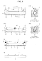
- a portion of a tubular body 1 which is a circular tube in a raw configuration is formed into an approximately U-shape in cross section ( Fig. 3 ) by crushing the portion of the tubular body in the radial direction.
- bending curvature radius R which sets a bottom line 3 as a back side (outer side of bending) is simultaneously performed.
- a second step Fig.
- bending (curvature radius R) which sets the bottom line 3 as a belly side (inner side of bending) is performed for forming a torsion beam having a straight part shape.
- Bending in the first step is performed such that a bending strain of 2 to 6% on a tensile TS side is imparted to an ear portion 2 by bending in the second step (unbending from the bent part shape into the straight part shape).
- a bending strain on a compression CP side is imparted to the bottom line 3.
- the curvature radius R in the first step is set with respect to the part height h of the torsion beam such that a bending strain ⁇ on a tensile TS side of the ear portion defined by a following formula (1) using a part height h of the torsion beam and the curvature radius R in the first step becomes 2 to 6%.
- Formula 1 ⁇ h / 2 ⁇ R + h ⁇ 100 %
- a torsion beam having a bent part shape is to be manufactured by the present invention (1), for example, as shown in Fig. 2 , in a first step ( Fig. 2(a) ), a portion of a tubular body 1 which is a circular tube in a raw configuration is formed into an approximately U-shape in cross section ( Fig. 3 ) by crushing the portion of the tubular body in the radial direction. In this step, a bottom line 3 is not bent and is held straight. Then, in a second step ( Fig. 2(b) ), bending which sets the bottom line 3 as a belly side (inner side of bending) is performed for forming a torsion beam having a bent part shape.
- Bending in the second step is performed such that a bending strain of 2 to 6% on a tensile TS side is imparted to an ear portion 2.
- a bending strain on a compression CP side is imparted to the bottom line 3. That is, the curvature radius R in the second step is set with respect to a part height h of the torsion beam such that a bending strain ⁇ on a tensile TS side of the ear portion 2 defined by a following formula (2) using a part height h of the torsion beam and the curvature radius R in the second step becomes 2 to 6%.
- Formula 2 ⁇ h / 2 ⁇ R - h ⁇ 100 %
- Fig. 4 shows one example of a result of the investigation of endurance lifetime (or fatigue life) (the number of times) obtained by carrying out a following fatigue test. Forming in the first step ( Fig. 1(a) ) and forming in the second step ( Fig. 2(b) ) shown in Fig.
- a tubular body which is a circular tube in a raw configuration and has a tensile strength of 780MPa, an outer diameter of 101.6mm, a wall thickness of 3.4mm and a length of 1200mm, wherein a level of a bending strain on a tensile TS side of the ear portion 2 is changed thus manufacturing a torsion beam having a straight part shape.
- the fatigue test which imitates a repeated stress loaded state which the torsion beam mounted on a compact car is estimated to receive is performed with respect to the manufactured torsion beam. It is understood from Fig. 4 that the endurance lifetime is largely enhanced when the bending strain is within a range of 2 to 6%. To the contrary, when the bending strain is less than 2%, the endurance lifetime enhancing effect is insufficient, while when the bending strain exceeds 6%, a defective shape occurs and hence, endurance lifetime is largely lowered whereby the torsion beam cannot be manufactured.
- the bending may be applied only to high risk parts FC of the fatigue crack initiation (for example, boundary portions between crushed portions and non-crushed portions, hereinafter referred to as gradually changing portions 7A) shown in Fig. 5(a), Fig. 5(b) without applying the bending over the whole tube longitudinal direction.
- the region BW where the bending in the second step is performed is not only limited to the high risk parts FC of the fatigue crack initiation, and bending may be applied to other parts when necessary.
- the highest risk part FC among the high risk parts of the fatigue crack initiation is the ear portion 7 of the gradually changing part 7A and hence, in the present invention (1), it is preferable to perform forming such that the bending strain of 2 to 6% in the longitudinal direction on a tensile TS side is imparted at least to the ear portion 7 of the gradually changing part 7A eventually.
- the present inventions (2) to (7) provide a torsion beam manufacturing method which specifically forms a torsion beam using dies. According to these inventions, it is possible to reduce a residual stress in a fatigue high risk part without applying a fluid pressure to the inside of the tubular body during forming from the raw tube to the torsion beam.
- the present invention (8) a fluid pressure is applied to the inside of a tubular body during forming in any one of the present inventions (1) to (7). Due to such an operation, the present invention (8) can provide a torsion beam product which exhibits high dimensional accuracy (with small warp or torsion in the longitudinal direction or with small distortion of surface) in addition to the reduction of a residual stress.
- the present invention (9) can provide a forming method which is suitable for forming a torsion beam having a straight part shape and uses both bending and the application of a fluid pressure loading.
- the present invention (10) provides a torsion beam which exhibits excellent torsional fatigue characteristics by restricting a residual stress in the ear portion 7 of the gradually changing part 7A in a product manufactured by the manufacturing method of any one of the present inventions (1) to (9).
- the present invention (2) is explained.
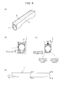
- a torsion beam by forming a tubular body, for example, as shown in Fig. 6 (a-1) and Fig, 6 (a-2)(tube set), a vertically movable ship-bottom-shaped upper die 4 where upward tapered portions 42 are contiguously formed with both ends of an upper horizontal portion 41, upper clamps 6 which are arranged on both end sides of the upper die 4 in a vertically movable manner, and a fixed lower die 5 where downward tapered portions 52 are contiguously formed with both ends of the lower horizontal portion 51 are used.
- Fig. 6 (a-1) and Fig, 6 (a-2)(tube set) a vertically movable ship-bottom-shaped upper die 4 where upward tapered portions 42 are contiguously formed with both ends of an upper horizontal portion 41, upper clamps 6 which are arranged on both end sides of the upper die 4 in a vertically movable manner, and a fixed lower die 5 where downward tapered portions 52 are contiguously formed with both
- a portion of the tubular body 1 is formed into an approximately V-shape in cross section (or an approximately U-shape in cross section also) by crushing the portion of the tubular body 1 in the radial direction by the upper die 4 and the lower die 5 and, thereafter, as shown in Fig. 6 (c) (crushing both tube ends), both tube end portions are clamped and are bent by the upper clamps 6 and the downward tapered portions 52 of the lower die 5 with the bottom line 3 set as the inner side of bending.
- a bending strain of 2 to 6% in the tube longitudinal direction on a tensile TS side is imparted to the ear portions 7 of the gradually changing portions 7A shown in Fig. 7 .
- Fig. 7 is an explanatory view showing a state where the bending strain on the tensile TS side is imparted to the ear portions 7 of the gradually changing portions 7A according to the present invention, wherein the stage of crushing by the upper die shown in Fig. 6 (b-1) and Fig. 6 (b-2) corresponds to Fig. 7(a) , and the stage of taking out the tubular body shown in Fig. 6(d) after the stage of crushing both tube ends shown in Fig. 6 (c) (after a springback) corresponds to Fig. 7(b) .
- the ear portions 7 of the gradually changing portions 7A are in an upwardly warped and bent state in Fig. 7(a) and are in a substantially flat state in Fig. 7(b) and hence, eventually, a bending strain on a tensile side is imparted due to bending with the bottom line 3 set as the inner side of bending.
- the residual stress distribution in the wall thickness direction in the ear portion 7 of the gradually changing portion 7 which occurs in an initial forming stage of the forming of the tubular body into an approximately V-shape in cross section (V-shaped press; Fig. 6 (b-1) and Fig. 6 (b-2)) (ear portion forming stage) occurs mainly when the tubular body receives folding in the circumferential direction.
- V-shaped press Fig. 6 (b-1) and Fig. 6 (b-2)
- strain on a tensile TS side acts in the longitudinal direction on both inner and outer surfaces of the ear portion 7 of the gradually changing portion 7A and hence, the residual stress distribution changes whereby the residual tensile stress in the inner surface of the ear portion 7 of the gradually changing portion 7A can be reduced.
- the present invention (3) is explained.
- a tube longitudinal center portion of a tubular body 1 is preliminarily formed into an approximately inverted-triangular-shape in cross section (inverted-triangular-shaped prepress), and preshaping which applies warp deformation to tube ends in the direction that a V-shaped bottom center portion projects downward is performed.
- the inverted-triangular-shaped prepressing and the forming of the warp deformation can be completed with one press operation.
- the bottom portion having the approximately inverted-triangular-shape in cross section may have an approximately U shape in place of the approximately V shape in this embodiment.
- a vertically movable ship-bottom-shaped upper die 4 where upward tapered portions 42 are contiguously formed with both ends of an upper horizontal portion 41, upper clamps 6 which are arranged on both end sides of the upper die 4 in a vertically movable manner, and a fixed lower die 5 where downward tapered portions 52 are contiguously formed with both ends of the lower horizontal portion 51 are used ( Fig. 9 (a-1) and Fig, 9 (a-2)(tube set)).
- a portion of the tubular body 1 is formed into an approximately V-shape in cross section (or an approximately U-shape in cross section) by crushing the portion of the tubular body 1 in the radial direction by the upper die 4 and the lower die 5 ( Fig.
- the stage of crushing by the upper die shown in Fig. 9 (b-1) and Fig. 9 (b-2) correspond to Fig. 7(a)
- the stage of taking out the tubular body in Fig. 9(d) after the stage of crushing both tube ends shown in Fig. 9(c) (after a springback) corresponds to Fig. 7(b)
- the ear portions 7 of the gradually changing portions 7A are in an upwardly warped and bent state in Fig. 7(a) and are in a substantially flat state in Fig. 7(b) and hence, eventually, a bending strain on a tensile side is imparted due to bending with the bottom line 3 set as the inner side of bending.
- the residual stress distribution in the wall thickness direction in the ear portion 7 of the gradually changing portion 7A which occurs in an initial forming stage of the forming of the tubular body into an approximately V-shape in cross section (V-shaped press; Fig. 9 (b-1) and Fig. 9 (b-2)) (ear portion forming stage) occurs mainly when the tubular body receives folding in the circumferential direction.
- V-shaped press V-shaped press
- Fig. 9 (b-1) and Fig. 9 (b-2) ear portion forming stage
- strain on a tensile side acts in the longitudinal direction on both inner and outer surfaces of the ear portion 7 of the gradually changing portion 7A and hence, the residual stress distribution changes whereby the residual tensile stress in the inner surface of the ear portion 7 of the gradually changing portion 7A can be reduced.
- the present invention (3) uses two pressing steps. Accordingly, although the number of dies to be used in manufacturing the same torsion beam (total forming amount being the same) is increased compared to a case where one press step is used, a press load in each step can be lowered.
- the present invention (4) is explained.
- a vertically movable ship-bottom-shaped upper die 4 where upward tapered portions 42 are contiguously formed with both ends of an upper horizontal portion 41, upper clamps 6 which are arranged on both end sides of the upper die 4 in a vertically movable manner, a vertically movable lower die 10 where vertical portions 103 are contiguously formed with both ends of a lower horizontal portion 101, and lower clamps 11 which are arranged on both end sides of the lower die 10 in a fixed manner are used ( Fig. 10 (a-1) and Fig. 10 (a-2)(tube set).
- a portion of the tubular body 1 is formed into an approximately V-shape in cross section (or an approximately U-shape in cross section also) by crushing the portion of the tubular body 1 in the radial direction by the upper die 4 and the lower die 10 and, at the same time, warp deformation is applied to the tubular body 1 in the direction that the tube center portion projects downward by three points bending by the upper die 4 and the lower clamps 11 (( Fig. 10 (b-1) and Fig. 10 (b-2) (V-press forming(lower the upper die and elevate the lower die).
- both tube end portions are clamped by the upper clamps 6 and the lower clamps 11 and, at the same time, the upper and lower dies 4, 10 are elevated with respect to the lower clamps 11 while maintaining a tube center portion clamping state thus applying bending to the tubular body 1 with the bottom line 3 set as the inner side of bending (( Fig. 10(c) (elevating the upper and lower dies, and lowering the tube end clamps)). Due to such bending (bending straightening), a bending strain of 2 to 6% in the tube longitudinal direction on a tensile TS side is imparted to the ear portions 7 of the gradually changing portions 7A shown in Fig. 7 .
- the V-shaped press forming stage shown in Fig. 10 (b-1) and Fig. 10 (b-2) corresponds to Fig. 7(a)
- the stage of taking out the tubular body after the stage shown in Fig. 10(c),(d) is finished corresponds to Fig. 7(b)
- the ear portions 7 of the gradually changing portions 7A are in an upwardly warped and bent state in Fig. 7(a) and are in a substantially flat state in Fig. 7(b) and hence, eventually, a bending strain on a tensile TS side is imparted due to bending with the bottom line 3 set as the inner side of bending.
- the residual stress distribution in the wall thickness direction in the ear portion 7 of the gradually changing portion 7A which occurs in an initial forming stage (ear portion forming stage) of V-shaped press forming occurs mainly when the tubular body receives folding in the circumferential direction.
- Fig. 10 (b-1) and Fig. 10 (b-2) occurs mainly when the tubular body receives folding in the circumferential direction.
- strain on a tensile TS side acts in the longitudinal direction on both inner and outer surfaces of the ear portion 7 of the gradually changing portion 7A and hence, the residual stress distribution changes whereby the residual tensile stress in the inner surface of the ear portion 7 of the gradually changing portion 7A can be reduced.
- a bending amount of the tubular body 1 in the tube longitudinal direction can be adjusted by lowering and elevation of the lower die 10 and hence, compared to a case where the fixed lower die 5 is used, a control range of an amount of bending strain on a tensile side imparted to the ear portion 7 of the gradually changing portion 7A can be broadened.
- the present invention (5) is explained.
- a vertically movable ship-bottom-shaped upper die 4 where upward tapered portions 42 are contiguously formed with both ends of an upper horizontal portion 41, upper clamps 6 which are arranged on both end sides of the upper die 4 in a vertically movable manner (interlockingly movable with the upper die 4 and vertically movable independently from the upper die 4), a fixed lower die 5 where vertical portions 53 are contiguously formed with both ends of the lower horizontal portion 51, and warp accelerating rotary dies 12 which are arranged on both end sides of the lower die 5 are used.
- a tubular body 1 is set ( Fig. 11(a) (tube set)).
- a portion of the tubular body 1 is formed into an approximately V-shape in cross section or an approximately U-shape in cross section by crushing the portion of the tubular body 1 in the radial direction by the upper and lower dies 4, 5 and, at the same time, warp deformation is applied to the tubular body in the direction that the tube center portion projects downward by three points bending by the upper die 4 and the warp accelerating rotary dies 12 in an upwardly rotating state ( Fig. 11(b) (crushing by upper die + rotation of warp accelerating dies).
- both tube end portions are clamped and are bent by the upper clamps 6 and the warp accelerating rotary dies 12 in a downwardly rotating state with the bottom line 3 set as the inner side of bending. Due to such bending (bending straightening), a bending strain of 2 to 6% in the tube longitudinal direction on a tensile TS side is imparted to the ear portions 7 of the gradually changing portions 7A ( Fig. 11(c) (both tube end crushing + rotation of warp accelerating dies)).
- the tubular body 1 can have a straight part shape after the removal of a load and the springback ( Fig. 11(d) (tubular body taken out after releasing clamping of upper die and both tube ends)).
- Fig. 11(d) tubular body taken out after releasing clamping of upper die and both tube ends
- an upward warp amount of the tubular body 1 can be easily controlled by adjusting a rotational angle of the warp accelerating rotary dies and hence, stable inline bending straightening can be realized irrespective of a tube size or a tube material.
- the inline bending straightening used in the present invention means forming including straightening by bending in a torsion beam forming step.
- the inline bending straightening method of the present invention (5) is advantageous because a post treatment step using other facility becomes unnecessary after forming a torsion beam leading to the reduction of manufacturing cost.
- the present invention (6) is explained.
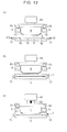
- a vertically movable ship-bottom-shaped upper die 4 where upward tapered portions 42 are contiguously formed with both ends of an upper horizontal portion 41, upper clamps 6 which are arranged on both end sides of the upper die 4 in a vertically movable manner (interlockingly movable with the upper die 4 and vertically movable independently from the upper die 4), a fixed lower die 5 where downward tapered portions 52 are contiguously formed with both ends of the lower horizontal portion 51, and warp accelerating advancing/retracting dies 13 having a tapered shape which are arranged on both end sides of the lower mold 5 are used.
- Fig. 12(a) advancing warp accelerating dies
- the warp accelerating advancing/retracting dies 13 are advanced to a position where the warp accelerating advancing/retracting dies 13 overlap with the downward tapered portions 52, and the tubular body 1 is set ( Fig. 12(b) (tube set).
- a portion of the tubular body 1 is formed into an approximately U-shape in cross section or an approximately V-shape in cross section by crushing the portion of the tubular body 1 in the radial direction by the upper die 4 and the lower die 5 and, at the same time, warp deformation is applied to the tubular body 1 in the direction that the tube center portion projects downward by three points bending by the upper die 4 and the advanced warp accelerating advancing/retracting dies 13 ( Fig. 12(c) (crushing by upper die). Thereafter, the upper die 4 is released ( Fig. 13(a) ) and the warp accelerating advancing/retracting dies 13 are retracted ( Fig. 13(b) ).
- both tube end portions are clamped and are bent by the upper clamps 6 and the downward tapered portion 52 while clamping the tube center portion by the upper and lower dies 4, 5 with the bottom line 3 set as the inner side of bending. Due to such bending (bending straightening), a bending strain of 2 to 6% in the tube longitudinal direction on a tensile TS side is imparted to the ear portions 7 of the gradually changing portions 7A ( Fig. 13(c) (crushing both tube ends).
- the tubular body 1 can have a straight part shape after the removal of a load and the springback ( Fig. 13(d) (tubular body taken out after releasing upper die and clamping of both tube ends)).
- an upward warp amount of the tubular body 1 can be easily controlled by adjusting a taper angle of the warp accelerating advancing/retracting dies 13 and hence, stable inline bending straightening can be realized irrespective of a tube size or a tube material.
- the inline bending straightening method of the present invention (6) is advantageous because a post treatment step using other facility becomes unnecessary after forming a torsion beam leading to the reduction of manufacturing cost.
- the present invention (7) is explained.
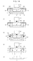
- a vertically movable ship-bottom-shaped upper die 4 where upward tapered portions 42 are contiguously formed with both ends of an upper horizontal portion 41
- upper clamps 14 which are arranged on both end sides of the upper die 4 in an interlocking manner with the upper die 4 and in an advanceable and retractable manner to and from the upper die 4
- a fixed lower die 5 where downward tapered portions 52 are contiguously formed with both ends of the lower horizontal portion 51 are used.
- 14A indicates an upper clamp advancing and retracting drive means (hydraulic cylinder or the like).
- the tubular body 1 is set ( Fig. 14(a) (tube set)).
- a portion of the tubular body 1 is crushed in the radial direction by the upper die 4 and the lower die 5 thus applying warp deformation to the tubular body 1 in the direction that the tube center portion project downward while forming the portion of the tubular body 1 into an approximately U-shape in cross section or an approximately V-shape in cross section ( Fig. 14(b) (crushing by the upper die).
- the upper die 4 is elevated and the upper clamps 14 are advanced ( Fig.
- the tubular body 1 can eventually have a straight part shape after the removal of a load and the springback ( Fig. 14(e) ).
- the upper clamps perform both applying a load and releasing the load in the vertical direction as the upper die elevating/lowering drive means, and does not receive a reaction force from the tube end portions at the time of elevating/lowering driving and hence, power (capacity) of the upper clamp advancing/retracting drive means 14A can be set smaller than power of the previously-mentioned upper clamp elevating/lowering drive means 6A (receiving a reaction force from the tube end portions at the time of advancing/retracting driving) whereby the installation cost can be reduced.
- the present invention (8) is explained.
- a fluid pressure is applied to the inside of the tubular body.
- the stage where the fluid pressure is applied to the inside of the tubular body may be performed only in the final stage of forming, and stages other than the final stage may be added to the final stage.
- the fluid pressure may be applied to the inside of the tubular body in stages ranging from a stage before starting forming the tubular body 1 to the removal of the load after the bending straightening (in all stages of forming).
- a fluid pressure applying means which applies a fluid pressure to the inside of the tube may be constituted of a pressure booster 20, a feedwater valve 21, seal caps 22, 23, an air release valve 24 and the like.
- the present invention (9) is explained.
- a torsion beam having a straight part shape by forming a tubular body 1 ( Fig. 15 (e) (tubular body taken out after releasing sealing and clamping by an upper die), a vertically movable ship-bottom-shaped upper die 4 where upward tapered portions 42 are contiguously formed with both ends of an upper horizontal portion 41, upper clamps 6 which are arranged on both end sides of the upper die 4 in a vertically movable manner, and a fixed lower die 5 where a lower horizontal portion 51 has a length equal to or larger than a tube length are used.
- a tubular body 1 is set ( Fig. 15(a) ) and, in a state where the upper clamps 6 are elevated, a portion of the tubular body 1 is crushed in the radial direction by the upper die 4 and the lower die 5 thus applying warp deformation to the tubular body 1 in the direction that the tube center portion projects downward ( Fig. 15(b) (crushing by the upper die) while forming the portion of the tubular body 1 into an approximately U-shape in cross section or an approximately V-shape in cross section. Thereafter, both tube end portions are clamped and are bent by the upper clamps 6 and the lower die 5 with the bottom line 3 set as the inner side of bending.
- a bending strain of 2 to 6% in the tube longitudinal direction on a tensile TS side is imparted to the ear portions 7 of the gradually changing portions 7A ( Fig. 15(c) (crushing both tube ends)).
- a fluid pressure is applied to the inside of the tubular body.
- a fluid pressure load FP applying means may be configured such that, for example, as shown in Fig. 15 , a liquid can be fed to a seal cap 22 which constitutes one of seal caps 22, 23 by a pressure booster 20 by way of a feedwater valve 21, and air can be released from the seal cap 23 which constitutes the other seal cap 23 by way of an air release valve 24.
- the seal caps 22, 23 are mounted on one tube end opening and the other tube end opening respectively and these seal caps 22, 23 are sealed and, then, a liquid (for example, water) which is pressurized by the pressure booster 20 is supplied (fluid pressure is applied) by opening the feedwater valve 21 and, at the same time, air is released by opening/closing (or setting to a proper opening) the air release valve 24 ( Fig. 15(d) ).
- a liquid for example, water
- the fluid pressure may be applied to the tubular body 1 in a state where stages other than the final stage are added to the final stage.
- the fluid pressure may be applied to the inside of the tubular body in stages ranging from a stage before starting forming the tubular body 1 to the removal of the load after the bending straightening (in all stages of forming).
- a forming device and a fluid pressure applying means which are substantially equal to the forming device and the fluid pressure applying means shown in Fig. 15 are used in the embodiment shown in Fig.
- the fluid pressure applying means is mounted on the tubular body 1 before the forming is started ( Fig. 16(a) (setting tube + sealing both tube ends)), forming is performed while keeping the applying of the fluid pressure to the tubular body ( Fig. 16(b) (crushing the tubular body by the upper die in a state where the fluid pressure is applied to the inside of the tubular body) and Fig. 16(c) (crushing both tube ends in a state where a fluid pressure is applied to the inside of the tubular body), and the fluid pressure is applied to the inside of the tubular body until the load is released.
- the present invention it is possible to provide a torsion beam product which exhibits high dimensional accuracy (with small warp or torsion in the longitudinal direction or with small distortion of surface) in addition to the reduction of the residual stress. Further, according to such an operation, a springback after the removal of a load can be made small and hence, in preparing a die design, it is unnecessary to add an error caused by the springback to a target shape which a final product aims at whereby the designing of the die is simplified. Further, a simple-shaped lower die having a straight lower bottom line is used to form the tubular body into a straight part shape. Accordingly, in this case, a cost for manufacturing the lower die can be reduced compared to a case where a lower die having a relatively complicated shape with downward tapered portions 52 formed on both end sides of a lower horizontal portion 51 is used.
- the present invention (10) is explained.
- the present invention (10) is directed to a torsion beam manufactured using a raw tube by any one of the present inventions (1) to (9), wherein a residual stress ⁇ which is defined by a maximum value ⁇ max of a maximum principal stress within an ear lobule shape forming range in the ear portion of the gradually changing portion of the torsion beam is suppressed to 50% or less with respect to a yield stress YS of the raw tube.
- a residual stress ⁇ exceeds 50% of the yield stress YS.
- the maximum value ⁇ max of a maximum principal stress within the ear lobule shape forming range of the ear portion 7 of the gradually changing portion can be measured using a strain gauge cutout method or an X ray method.
- the yield stress YS of the raw tube can be obtained in accordance with a tensile test such as JIS12A or JIS11.
- a residual stress ratio ⁇ which is defined by the following formula (3) using ⁇ and YS is set to 50% or less ( ⁇ 50%).
- Formula 3 residual stress ratio ⁇ ⁇ / YS ⁇ 100 %
- the bending strain ⁇ on a tensile side imparted to the ear portion 2 is geometrically calculated based on a shape before the removal of a load.
- the bending strain ⁇ a is expressed in terms of a residual plastic bending strain ⁇ b after the removal of a load, although the relationship between ⁇ b and ⁇ a changes to some extent depending on a size of tubular body and a strength of a material, as shown in Fig. 18 later, by setting ⁇ a to 2% or more, ⁇ b becomes approximately 0.2% or more so that the relationship ⁇ 50% is obtained.
- a residual plastic bending strain ⁇ b on a tube outer surface of the ear portion after the removal of a load can be measured using a strain gauge method or the like, and is measured as a maximum principal strain ⁇ max.
- Fig. 17 shows one example of an off line bending straightening method and a measuring method of a bending strain and a residual stress. This example corresponds to a measurement performed in a second step shown in Fig. 5(b) where a bent part shape is obtained, and a material which becomes an object is a tubular body of 690MPa class which has a raw-tube size of ⁇ 89.1mm ⁇ t2.6mm ⁇ L1300mm.
- a strain gauge 30 is adhered to the ear portion 7 of the gradually changing portion of the tubular body 1, the tubular body 1 is set to a bending straightening device having a center die and pressing dies on both end sides (Fig.
- a residual stress ratio ⁇ obtained by changing a bending straightening amount and a residual plastic bending strain ⁇ b and a bending strain ⁇ a on a tensile side geometrically calculated based on a shape before the removal of a load is shown in Fig. 18 .
- ⁇ a is 2% or more ( ⁇ b being approximately 0.2% or more), y ⁇ 50% is satisfied with a margin.
- ⁇ a is approximately 4% or more ( ⁇ b being approximately 0.4% or more)
- ⁇ assumes a negative value, that is, ⁇ max is shifted from a tensile side to a compression side and hence, it is understood that a characteristic which is further advantageous in view of a torsion fatigue characteristic (characteristic exceeding part performance of a strain-removed annealed material) can be imparted.
- torsion beams were manufactured by forming tubular bodies made of raw tubes (tubes in raw configuration being circular tubes) shown in Table 1 under different forming conditions shown in Table 2 in the embodiment shown in Fig. 1 or Fig. 2 , and endurance lifetimes (the number of times) of these torsion beams were investigated by carrying out a fatigue test substantially equal to the above-mentioned fatigue test on the manufactured torsion beams.
- the result of the test is shown in Table 2. From Table 2, it is understood that the examples of the present invention exhibit extremely long endurance lifetimes compared to comparison examples, and no defective shape is found in the present invention examples.
- torsion beams were manufactured by forming tubular bodies of raw tubes (tubes in raw configuration being circular tubes) shown in Table 1 under different forming conditions shown in Table 3 in the embodiment of any one of the above-mentioned present inventions (2) to (9), and endurance lifetimes (the number of times) were investigated by carrying out a fatigue test substantially equal to the above-mentioned fatigue test on the manufactured torsion beams.
- the result of the test is shown in Table 3-1 to Table 3-4.
Abstract
Description
- The present invention relates to a torsion beam manufacturing method and a torsion beam, and more specifically to a torsion beam manufacturing method where a tubular body which is a circular tube in a raw configuration is formed into a torsion beam having an approximately U-shape or V-shape in cross section by forming, and a torsion beam which is manufactured by the torsion beam manufacturing method.
- As a background art relating to the torsion beam manufacturing method,
patent document 1 andpatent document 2 are named.
To consider a case where a torsion beam is manufactured in such a manner that a tubular body is manufactured by a normal tube manufacturing method (a tube manufacturing method where the rolling direction of a rolled steel sheet is set to the tub axis direction) and a portion of the tubular body is crushed in the radial direction, there exists a possibility that wrinkles which extend in the tube axis direction (longitudinal direction) are generated on inner peripheral surfaces of edge portions of a crushed portion in the circumferential direction in cross section (hereinafter the edge portions being referred to as ear portions since the edge portions have a shape similar to an ear of a rabbit). These wrinkles become a source of fatigue crank initiation and deteriorate the endurance of the torsion beam. To overcome such a drawback,patent document 1 has proposed the use of a tubular body manufactured by setting the rolling direction of a rolled steel sheet approximately perpendicular to the axial direction of the tubular body as a tubular body provided for crushing and forming in the radial direction and/or the grinding of an inner periphery of the tubular body in the direction approximately perpendicular to the axial direction of the tubular body before or after manufacturing the tube. -
Patent document 2, as a heat treatment method which enhances deformation strength and fatigue strength of car parts, proposes a method where torsion is applied to a steel material within a range where plastic deformation does not take place, heat treatment is applied to a portion to which a tensile stress is applied in such a torsion-applied state, and the torsion is released after cooling the steel material. Due to such a method, it is considered that the direction of the applied compressive residual stress can be easily aligned with the direction of a stress applied to the steel material during use and dimensional accuracy is enhanced due to the suppression of generations of strain in the steel material. -
- [Patent document 1]
JP-A-2005-289258 - [Patent document 2]
JP-A-2002-275538 - The above-mentioned background art is considered effective as a means which enhances the fatigue strength of the ear portion of the torsion beam which is a high risk part where fatigue crack initiations occur. In forming the portion of the tubular body into a cross section having an approximately U-shape (hereinafter referred to as an approximately U-shape in cross section) by crushing the portion in the radial direction, the ear portion is mainly subjected to bending in the circumferential direction and hence, a residual stress on a tensile side occurs on a tubular inner surface of the ear portion in the circumferential direction, and this residual stress causes lowering of fatigue characteristics. Although the technique disclosed in
patent document 1 is the technique which focuses on wrinkles formed on the tubular inner surface which becomes a source of a fatigue crack initiation, the occurrence of wrinkles can be avoided by designing a shape of the ear portion having a slightly larger curvature radius without forming an ear shape having a small curvature radius by which wrinkles occur. A means which reduces a tensile residual stress in the tubular inner surface of the ear portion is important for the enhancement of fatigue characteristics. - However, in the technique disclosed in
patent document 1, it is necessary to set the rolling direction of the rolled steel sheet substantially perpendicular to the axial direction of the tubular body and/or to grind the inner periphery of the tubular body in the tubular circumferential direction which is the direction approximately perpendicular to the axial direction of the tubular body. In this case, compared to a usual case, the large restriction is imposed on a length of a manufactured tube or the addition of the grinding step is necessary or the like and hence, there arises a drawback that the technique is disadvantageous in view of productivity and cost. Further, compared to a usual case, the technique disclosed inpatent document 2 requires the addition of steps such as applying torsion and heat treatment and hence, the technique also has a drawback that it is disadvantageous in view of productivity and cost in the same manner. - The present invention provides a means which can overcome the above-mentioned drawbacks, and can enhance fatigue strength of an ear portion which is a high risk part of the fatigue crack initiation in a torsion beam almost without bringing about disadvantages in terms of productivity and cost, and the gist of the present invention is as follows.
- (1) A torsion beam manufacturing method being characterized in that, in manufacturing a torsion beam by forming a tubular body, a portion of the tubular body is formed into an approximately U-shape in cross section or a shape having an approximately V shape in cross section (hereinafter referred to as an approximately V-shape in cross section) by crushing the portion of the tubular body in the radial direction and, thereafter, the tubular body is bent with a bottom line of the tubular body set as the inner side of bending so that a bending strain of 2 to 6% in the tube longitudinal direction on a tensile side is imparted to ear portions.
- (2) In the above-mentioned torsion beam manufacturing method (1), using a vertically movable ship-bottom-shaped upper die where tapered portions which are inclined upward (hereinafter referred to as upward tapered portions) are contiguously formed with both ends of a horizontal portion of the upper die (hereinafter referred to as an upper horizontal portion), upper clamps which are arranged on both end sides of the upper die in a vertically movable manner, and a fixed lower die where tapered portions which are inclined downward (hereinafter referred to as downward tapered portions) are contiguously formed with both ends of a horizontal portion of the lower die (hereinafter referred to as an lower horizontal portion), a portion of the tubular body is formed into an approximately U-shape in cross section or an approximately V-shape in cross section by crushing the portion of the tubular body in the radial direction by the upper die and the lower die and, thereafter, both tube end portions are clamped and bent by the upper clamps and the downward tapered portions of the lower die with the bottom line set as the inner side of bending and, due to the bending, a bending strain of 2 to 6% in the tube longitudinal direction on a tensile side is imparted to the ear portions of boundary portions between crushed portions and non-crushed portions (portions which are gradually changed, hereinafter referred to as gradually changing portions).
- (3) In the above-mentioned torsion beam manufacturing method (1) or (2), a tube longitudinal center portion of the tubular body is preliminarily formed into a shape whose cross section has an inverted triangle shape (hereinafter referred to as an approximately inverted-triangular-shape in cross section) and, at the same time, preshaping which applies warp deformation to tube ends in the direction that a bottom of the portion formed into an approximately V-shape in cross section projects downward is performed and, thereafter, using the vertically movable ship-bottom-shaped upper die where the upward tapered portions are contiguously formed with both ends of the upper horizontal portion, the upper clamps which are arranged on both end sides of the upper die in a vertically movable manner, and the fixed lower die where the downward tapered portions are contiguously formed with both of the lower horizontal portion, a portion of the tubular body is formed into an approximately U-shape in cross section or an approximately V-shape in cross section by crushing the portion of the tubular body in the radial direction by the upper die and the lower die and, thereafter, both tube end portions are clamped and are bent by the upper clamps and the downward tapered portions of the lower die with the bottom line set as the inner side of and, due to the bending, a bending strain of 2 to 6% in the tube longitudinal direction on a tensile side is imparted to the ear portions of the gradually changing portions.
- (4) In the above-mentioned torsion beam manufacturing method (1), using a vertically movable ship-bottom-shaped upper die where upward tapered portions are contiguously formed with both ends of an upper horizontal portion, upper clamps which are arranged on both end sides of the movable upper die in a vertically movable manner, a vertically movable lower die where vertical portions are contiguously formed with both ends of a lower horizontal portion, and lower clamps which are arranged on both end sides of the lower die in a fixed manner, a portion of the tubular body is formed into an approximately U-shape in cross section or an approximately V-shape in cross section by crushing the portion of the tubular body in the radial direction by the upper die and the lower die and, at the same time, warp deformation is applied to the tubular body in the direction that a tube center portion projects downward by three points bending by the upper die and the lower clamps and, thereafter, both tube end portions are clamped by the upper clamps and the lower clamps and, at the same time, the upper and lower dies are elevated with respect to the lower clamps while maintaining the tube center portion in a clamped state thus applying bending to the tubular body with the bottom line set as the inner side of bending and, due to the bending, a bending strain of 2 to 6% in the tube longitudinal direction on a tensile side is imparted to ear portions of gradually changing portions.
- (5) In the above-mentioned torsion beam manufacturing method (1), using a vertically movable ship-bottom-shaped upper die where upward tapered portions are contiguously formed with both ends of an upper horizontal portion, upper clamps which are arranged on both end sides of the upper die in a vertically movable manner, a fixed lower die where vertical portions are contiguously formed with both ends of a lower horizontal portion, and warp accelerating rotary dies which are arranged on both end sides of the lower die, a portion of the tubular body is formed into an approximately U-shape in cross section or an approximately V-shape in cross section by crushing the portion of the tubular body in the radial direction by the upper die and the lower die and, at the same time, warp deformation is applied to the tubular body in the direction that a tube center portion projects downward by three points bending by the upper die and the warp accelerating rotary dies in an upwardly rotating state and, thereafter, both tube end portions are clamped and are bent by the upper clamps and the warp accelerating rotary dies in a downwardly rotating state with the bottom line set as the inner side of bending and, due to the bending, a bending strain of 2 to 6% in the tube longitudinal direction on a tensile side is imparted to ear portions of gradually changing portions.
- (6) In the above-mentioned torsion beam manufacturing method (1) or (2), using the vertically movable ship-bottom-shaped upper die where the upward tapered portions are contiguously formed with both ends of the upper horizontal portion, the upper clamps which are arranged on both end sides of the upper die in a vertically movable manner, the fixed lower die where the downward tapered portions are contiguously formed with both ends of the lower horizontal portion, and warp accelerating advancing/retracting dies having a tapered shape which are arranged on both end sides of the lower die, a portion of the tubular body is formed into an approximately U-shape in cross section or an approximately V-shape in cross section by crushing the portion of the tubular body in the radial direction by the upper die and the lower die and, at the same time, warp deformation is applied to the tubular body in the direction that a tube center portion projects downward by three points bending by the upper die and the advanced warp accelerating advancing/retracting dies and, thereafter, the upper die is released and the warp accelerating advancing/retracting dies are retracted and, next, both tube end portions are clamped and bent by the upper clamps and the downward tapered portions while clamping the tube center portion by the upper and lower dies with the bottom line set as the inner side of bending and, due to the bending, a bending strain of 2 to 6% in the tube longitudinal direction on a tensile side is imparted to the ear portions of the gradually changing portions.
- (7) In the above-mentioned torsion beam manufacturing method (1) or (2), using the vertically movable ship-bottom-shaped upper die where the upward tapered portions are contiguously formed with both ends of the upper horizontal portion, upper clamps which are arranged on both end sides of the upper die in an interlocking manner with the upper die and in an advanceable and retractable manner to and from the upper die, and the fixed lower die where the downward tapered portions are contiguously formed with both ends of the upper horizontal portion,
in a state where the upper clamps are retracted, a portion of the tubular body is crushed in the radial direction by the upper die and the lower die thus applying warp deformation to the tubular body in the direction that a tube center portion projects downward while forming the portion of the tubular body into an approximately U-shape in cross section or an approximately V-shape in cross section and, thereafter, the upper die is elevated and the upper clamps are advanced and, next, the upper die is lowered so that both tube end portions are clamped and bent by the upper clamps and the downward tapered portions while clamping the tube center portion by the upper and lower dies with the bottom line set as the inner side of bending and, due to the bending, a bending strain of 2 to 6% in the tube longitudinal direction on a tensile side is imparted to the ear portions of the gradually changing portions. - (8) In any one of the above-mentioned torsion beam manufacturing method (1) to (7), at least in a final stage of forming, that is, in a stage ranging from holding a state where bending is applied to the tubular body with the bottom line set as the inner side of bending to the removal of a load, a fluid pressure is applied to the inside of the tubular body.
- (9) In the above-mentioned torsion beam manufacturing method (1), in a step where, in manufacturing a torsion beam having a straight part shape by forming a tubular body, using a vertically movable ship-bottom-shaped upper die where upward tapered portions are contiguously formed with both ends of an upper horizontal portion, upper clamps which are arranged on both end sides of the upper die in a vertically movable manner, and a fixed lower die where a lower horizontal portion has a length of a range equal to or larger than a length of the tubular body, in a state where the upper clamps are elevated, a portion of the tubular body is crushed in the radial direction by the upper die and the lower die thus applying warp deformation to the tubular body in the direction that a tube center portion projects downward while forming the portion of the tubular body into an approximately U-shape in cross section or an approximately V-shape in cross section and, thereafter, both tube end portions are clamped and are bent by the upper clamps and the lower die with the bottom line set as the inner side of bending and, due to the bending, a bending strain of 2 to 6% in the tube longitudinal direction on a tensile side is imparted to ear portions of gradually changing portions, at least in a final stage of forming, that is, in a stage ranging from holding a state where bending is applied to the tubular body with the bottom line set as the inner side of bending to the removal of a load, a fluid pressure is applied to the inside of the tubular body.
- (10) A torsion beam manufactured from a raw tube using any one of the above-mentioned manufacturing methods (1) to (9) being characterized in that, a residual stress σ which is defined by a maximum value of a maximum principal stress within an ear lobule shape forming range in the ear portion of the gradually changing portion of the torsion beam is suppressed to 50% or less with respect to a yield stress YS of the raw tube.
- With respect to the residual stress distribution in the wall thickness direction in the ear portion which occurs mainly when the tubular body receives folding in the circumferential direction at the time of forming the torsion beam, by carrying out the bending with the bottom line set as a belly side (also referred to as an inner side of bending) in a next stage, a strain on a tensile side acts in the longitudinal direction on both inner and outer surfaces of the
ear portion 2 and hence, the residual stress distribution changes whereby the residual tensile stress in the inner surface can be reduced.
According to the present invention, a residual tensile stress of theear portion 2 of the torsion beam can be reduced, and also work hardening can be applied to theear portion 2 so that a fatigue strength of theear portion 2 can be enhanced. With respect to steps, a step in which slight bending of 2 to 6% is applied is only added after the usual crushing step. That is, the restriction on a length of a manufactured tube is equal to the corresponding restriction in a usual manufacturing method, and it is unnecessary to add steps such as grinding, applying torsion and heat treatment and hence, disadvantages of the manufacturing method of the present invention in terms of productivity and cost are extremely small to be ignored. -
- [
Fig. 1 ]
A schematic side view showing one example of a case where a torsion beam having a straight part shape is manufactured by the present invention (1). - [
Fig. 2 ]
A schematic side view showing one example of a case where a torsion beam having a bent part shape is manufactured by the present invention (1). - [
Fig. 3 ]
A cross-sectional view taken along a line A-A (as viewed in the direction indicated by an arrow A-A) inFig. 1 or Fig. 2 . - [
Fig. 4 ]
A graph showing one example of a result of the investigation of the relationship between a bending strain on a tensile side imparted to anear portion 2 of the torsion beam and endurance lifetime (or fatigue life) obtained by a fatigue test. - [
Fig. 5 ]
A schematic side view showing one example of another embodiment according to thepresent invention 1. - [
Fig. 6 ]
A schematic view showing one example of an embodiment of the present invention (2). - [
Fig. 7 ]
An explanatory view showing a state where a a bending strain on a tensile side is applied to a gradually changingportion 7 of the ear portion in the present invention (2). - [
Fig. 8 ]
A schematic view showing one example of an embodiment of preshaping (first step) in the present invention (3). - [
Fig. 9 ]
A schematic view showing one example of an embodiment of forming (second step) after preshaping (first step) in the present invention (3). - [
Fig. 10 ]
A schematic view showing one example of the embodiment according to the present invention (4). - [
Fig. 11 ]
A schematic view showing one example of the embodiment according to the present invention (5). - [
Fig. 12 ]
A schematic view showing one example of the embodiment according to the present invention (6). - [
Fig. 13 ]
A schematic view showing one example of the embodiment according to the present invention (6) (continued fromFig. 12 ). - [
Fig. 14 ]
A schematic view showing one example of the embodiment according to the present invention (7). - [
Fig. 15 ]
A schematic view showing one example of the embodiment according to the present invention (9). - [
Fig. 16 ]
A schematic view showing another example of the embodiment according to the present invention (9). - [
Fig. 17 ]
An explanatory view showing a bending straightening (bending with abottom line 3 set as an inner side of bending) method and a measuring method of a bending strain and a residual stress. - [
Fig. 18 ]
A curve graph showing the relationship between a residual stress ratio γ and a bending strain εa on a tensile side geometrically calculated based on a shape before the removal of a load and a residual plastic bending strain εb after the removal of a load. - When a torsion beam having a straight part shape is to be manufactured by the present invention (1), for example, as shown in
Fig. 1 , in a first step (Fig. 1(a) ), a portion of atubular body 1 which is a circular tube in a raw configuration is formed into an approximately U-shape in cross section (Fig. 3 ) by crushing the portion of the tubular body in the radial direction. In this step, bending (curvature radius R) which sets abottom line 3 as a back side (outer side of bending) is simultaneously performed. Then, in a second step (Fig. 1(b) ), bending (curvature radius R) which sets thebottom line 3 as a belly side (inner side of bending) is performed for forming a torsion beam having a straight part shape. Bending in the first step is performed such that a bending strain of 2 to 6% on a tensile TS side is imparted to anear portion 2 by bending in the second step (unbending from the bent part shape into the straight part shape). On the other hand, a bending strain on a compression CP side is imparted to thebottom line 3. That is, the curvature radius R in the first step is set with respect to the part height h of the torsion beam such that a bending strain ε on a tensile TS side of the ear portion defined by a following formula (1) using a part height h of the torsion beam and the curvature radius R in the first step becomes 2 to 6%.
- On the other hand, when a torsion beam having a bent part shape is to be manufactured by the present invention (1), for example, as shown in
Fig. 2 , in a first step (Fig. 2(a) ), a portion of atubular body 1 which is a circular tube in a raw configuration is formed into an approximately U-shape in cross section (Fig. 3 ) by crushing the portion of the tubular body in the radial direction. In this step, abottom line 3 is not bent and is held straight. Then, in a second step (Fig. 2(b) ), bending which sets thebottom line 3 as a belly side (inner side of bending) is performed for forming a torsion beam having a bent part shape. Bending in the second step is performed such that a bending strain of 2 to 6% on a tensile TS side is imparted to anear portion 2. On the other hand, a bending strain on a compression CP side is imparted to thebottom line 3. That is, the curvature radius R in the second step is set with respect to a part height h of the torsion beam such that a bending strain ε on a tensile TS side of theear portion 2 defined by a following formula (2) using a part height h of the torsion beam and the curvature radius R in the second step becomes 2 to 6%.
- According to the present invention (1), by setting the bending strain on a tensile TS side imparted to the
ear portion 2 to 2 to 6%, a tensile residual stress in theear portion 2 can be effectively reduced without causing a defective shape, and fatigue strength can be enhanced by work hardening. For example,Fig. 4 shows one example of a result of the investigation of endurance lifetime (or fatigue life) (the number of times) obtained by carrying out a following fatigue test. Forming in the first step (Fig. 1(a) ) and forming in the second step (Fig. 2(b) ) shown inFig. 1 are applied to a tubular body which is a circular tube in a raw configuration and has a tensile strength of 780MPa, an outer diameter of 101.6mm, a wall thickness of 3.4mm and a length of 1200mm, wherein a level of a bending strain on a tensile TS side of theear portion 2 is changed thus manufacturing a torsion beam having a straight part shape. Then, the fatigue test which imitates a repeated stress loaded state which the torsion beam mounted on a compact car is estimated to receive is performed with respect to the manufactured torsion beam. It is understood fromFig. 4 that the endurance lifetime is largely enhanced when the bending strain is within a range of 2 to 6%. To the contrary, when the bending strain is less than 2%, the endurance lifetime enhancing effect is insufficient, while when the bending strain exceeds 6%, a defective shape occurs and hence, endurance lifetime is largely lowered whereby the torsion beam cannot be manufactured. - Further, in carrying out the present invention (1), with respect to a region BW where bending in the second step is performed, for example, depending on a case, the bending may be applied only to high risk parts FC of the fatigue crack initiation (for example, boundary portions between crushed portions and non-crushed portions, hereinafter referred to as gradually changing
portions 7A) shown inFig. 5(a), Fig. 5(b) without applying the bending over the whole tube longitudinal direction.
The region BW where the bending in the second step is performed is not only limited to the high risk parts FC of the fatigue crack initiation, and bending may be applied to other parts when necessary. The highest risk part FC among the high risk parts of the fatigue crack initiation is theear portion 7 of the gradually changingpart 7A and hence, in the present invention (1), it is preferable to perform forming such that the bending strain of 2 to 6% in the longitudinal direction on a tensile TS side is imparted at least to theear portion 7 of the gradually changingpart 7A eventually. - To impart the bending strain of 2 to 6% on a tensile TS side to the
ear portion 7 of the gradually changingpart 7A eventually, the present inventions (2) to (7) provide a torsion beam manufacturing method which specifically forms a torsion beam using dies. According to these inventions, it is possible to reduce a residual stress in a fatigue high risk part without applying a fluid pressure to the inside of the tubular body during forming from the raw tube to the torsion beam. - Further, in the present invention (8), a fluid pressure is applied to the inside of a tubular body during forming in any one of the present inventions (1) to (7). Due to such an operation, the present invention (8) can provide a torsion beam product which exhibits high dimensional accuracy (with small warp or torsion in the longitudinal direction or with small distortion of surface) in addition to the reduction of a residual stress.
- The present invention (9) can provide a forming method which is suitable for forming a torsion beam having a straight part shape and uses both bending and the application of a fluid pressure loading.
The present invention (10) provides a torsion beam which exhibits excellent torsional fatigue characteristics by restricting a residual stress in theear portion 7 of the gradually changingpart 7A in a product manufactured by the manufacturing method of any one of the present inventions (1) to (9). - The present invention (2) is explained.
In the present invention (2), in manufacturing a torsion beam by forming a tubular body, for example, as shown inFig. 6 (a-1) andFig, 6 (a-2)(tube set), a vertically movable ship-bottom-shaped upper die 4 where upward taperedportions 42 are contiguously formed with both ends of an upperhorizontal portion 41,upper clamps 6 which are arranged on both end sides of theupper die 4 in a vertically movable manner, and a fixed lower die 5 where downward taperedportions 52 are contiguously formed with both ends of the lowerhorizontal portion 51 are used. As shown inFig. 6 (b-1) andFig, 6 (b-2) (crushing by the upper die), a portion of thetubular body 1 is formed into an approximately V-shape in cross section (or an approximately U-shape in cross section also) by crushing the portion of thetubular body 1 in the radial direction by theupper die 4 and thelower die 5 and, thereafter, as shown inFig. 6 (c) (crushing both tube ends), both tube end portions are clamped and are bent by theupper clamps 6 and the downward taperedportions 52 of thelower die 5 with thebottom line 3 set as the inner side of bending. Due to such bending (also referred to as bending straightening, the same definition being applicable hereinafter)), a bending strain of 2 to 6% in the tube longitudinal direction on a tensile TS side is imparted to theear portions 7 of the gradually changingportions 7A shown inFig. 7 . -
Fig. 7 is an explanatory view showing a state where the bending strain on the tensile TS side is imparted to theear portions 7 of the gradually changingportions 7A according to the present invention, wherein the stage of crushing by the upper die shown inFig. 6 (b-1) andFig. 6 (b-2) corresponds toFig. 7(a) , and the stage of taking out the tubular body shown inFig. 6(d) after the stage of crushing both tube ends shown inFig. 6 (c) (after a springback) corresponds toFig. 7(b) . Theear portions 7 of the gradually changingportions 7A are in an upwardly warped and bent state inFig. 7(a) and are in a substantially flat state inFig. 7(b) and hence, eventually, a bending strain on a tensile side is imparted due to bending with thebottom line 3 set as the inner side of bending. - The residual stress distribution in the wall thickness direction in the
ear portion 7 of the gradually changingportion 7 which occurs in an initial forming stage of the forming of the tubular body into an approximately V-shape in cross section (V-shaped press;Fig. 6 (b-1) andFig. 6 (b-2)) (ear portion forming stage) occurs mainly when the tubular body receives folding in the circumferential direction. However, by carrying out the bending with thebottom line 3 set as the inner side of bending in a final stage of forming (Fig. 6(c) ), strain on a tensile TS side acts in the longitudinal direction on both inner and outer surfaces of theear portion 7 of the gradually changingportion 7A and hence, the residual stress distribution changes whereby the residual tensile stress in the inner surface of theear portion 7 of the gradually changingportion 7A can be reduced. - The present invention (3) is explained.
In the present invention (3), in manufacturing a torsion beam by forming a tubular body, for example, as shown inFig. 8 , as a first step, a tube longitudinal center portion of atubular body 1 is preliminarily formed into an approximately inverted-triangular-shape in cross section (inverted-triangular-shaped prepress), and preshaping which applies warp deformation to tube ends in the direction that a V-shaped bottom center portion projects downward is performed. In the first step, although an inverted-triangular-shaped prepressupper die 8 and an inverted-triangular-shaped prepresslower die 9 shown inFig. 8(a) are used, by setting a V-bottom portion of the inverted-triangular-shaped prepresslower die 9 at the longitudinal center lower than semicircular bottom portions of the inverted-triangular-shaped prepresslower die 9 at both longitudinal ends by a gap δ (>0) after forming (Fig. 8(c), (d) ), the inverted-triangular-shaped prepressing and the forming of the warp deformation can be completed with one press operation. The bottom portion having the approximately inverted-triangular-shape in cross section may have an approximately U shape in place of the approximately V shape in this embodiment.
Next, for example, as shown inFig. 9 , as a second step, a vertically movable ship-bottom-shaped upper die 4 where upward taperedportions 42 are contiguously formed with both ends of an upperhorizontal portion 41,upper clamps 6 which are arranged on both end sides of theupper die 4 in a vertically movable manner, and a fixed lower die 5 where downward taperedportions 52 are contiguously formed with both ends of the lowerhorizontal portion 51 are used (Fig. 9 (a-1) andFig, 9 (a-2)(tube set)). A portion of thetubular body 1 is formed into an approximately V-shape in cross section (or an approximately U-shape in cross section) by crushing the portion of thetubular body 1 in the radial direction by theupper die 4 and the lower die 5 (Fig. 9 (b-1) andFig, 9 (b-2) (crushing by upper die)) and, thereafter, both tube end portions are clamped and are bent by theupper clamps 6 and the downward taperedportions 52 of thelower die 5 with thebottom line 3 set as the inner side of bending (Fig. 9(c) (crushing both tube ends)). Due to such bending (bending straightening), a bending strain of 2 to 6% in the tube longitudinal direction on a tensile TS side is imparted to theear portions 7 of the gradually changingportions 7A shown inFig. 7 . - The stage of crushing by the upper die shown in
Fig. 9 (b-1) andFig. 9 (b-2) correspond toFig. 7(a) , and the stage of taking out the tubular body inFig. 9(d) after the stage of crushing both tube ends shown inFig. 9(c) (after a springback) corresponds toFig. 7(b) . Theear portions 7 of the gradually changingportions 7A are in an upwardly warped and bent state inFig. 7(a) and are in a substantially flat state inFig. 7(b) and hence, eventually, a bending strain on a tensile side is imparted due to bending with thebottom line 3 set as the inner side of bending. - The residual stress distribution in the wall thickness direction in the
ear portion 7 of the gradually changingportion 7A which occurs in an initial forming stage of the forming of the tubular body into an approximately V-shape in cross section (V-shaped press;Fig. 9 (b-1) andFig. 9 (b-2)) (ear portion forming stage) occurs mainly when the tubular body receives folding in the circumferential direction. However, by carrying out the bending with thebottom line 3 set as the inner side of bending in a final stage of forming (Fig. 9(c) ), strain on a tensile side acts in the longitudinal direction on both inner and outer surfaces of theear portion 7 of the gradually changingportion 7A and hence, the residual stress distribution changes whereby the residual tensile stress in the inner surface of theear portion 7 of the gradually changingportion 7A can be reduced. The present invention (3) uses two pressing steps. Accordingly, although the number of dies to be used in manufacturing the same torsion beam (total forming amount being the same) is increased compared to a case where one press step is used, a press load in each step can be lowered. - The present invention (4) is explained.
In the present invention (4), in manufacturing a torsion beam by forming a tubular body, for example, as shown inFig. 10 , a vertically movable ship-bottom-shaped upper die 4 where upward taperedportions 42 are contiguously formed with both ends of an upperhorizontal portion 41,upper clamps 6 which are arranged on both end sides of theupper die 4 in a vertically movable manner, a vertically movable lower die 10 wherevertical portions 103 are contiguously formed with both ends of a lowerhorizontal portion 101, andlower clamps 11 which are arranged on both end sides of thelower die 10 in a fixed manner are used (Fig. 10 (a-1) andFig. 10 (a-2)(tube set). A portion of thetubular body 1 is formed into an approximately V-shape in cross section (or an approximately U-shape in cross section also) by crushing the portion of thetubular body 1 in the radial direction by theupper die 4 and thelower die 10 and, at the same time, warp deformation is applied to thetubular body 1 in the direction that the tube center portion projects downward by three points bending by theupper die 4 and the lower clamps 11 ((Fig. 10 (b-1) andFig. 10 (b-2) (V-press forming(lower the upper die and elevate the lower die). Thereafter, both tube end portions are clamped by theupper clamps 6 and thelower clamps 11 and, at the same time, the upper and lower dies 4, 10 are elevated with respect to the lower clamps 11 while maintaining a tube center portion clamping state thus applying bending to thetubular body 1 with thebottom line 3 set as the inner side of bending ((Fig. 10(c) (elevating the upper and lower dies, and lowering the tube end clamps)). Due to such bending (bending straightening), a bending strain of 2 to 6% in the tube longitudinal direction on a tensile TS side is imparted to theear portions 7 of the gradually changingportions 7A shown inFig. 7 . - The V-shaped press forming stage shown in
Fig. 10 (b-1) andFig. 10 (b-2) corresponds toFig. 7(a) , and the stage of taking out the tubular body after the stage shown inFig. 10(c),(d) is finished (after a springback) corresponds toFig. 7(b) . Theear portions 7 of the gradually changingportions 7A are in an upwardly warped and bent state inFig. 7(a) and are in a substantially flat state inFig. 7(b) and hence, eventually, a bending strain on a tensile TS side is imparted due to bending with thebottom line 3 set as the inner side of bending. - The residual stress distribution in the wall thickness direction in the
ear portion 7 of the gradually changingportion 7A which occurs in an initial forming stage (ear portion forming stage) of V-shaped press forming (Fig. 10 (b-1) andFig. 10 (b-2)) occurs mainly when the tubular body receives folding in the circumferential direction. However, by carrying out the bending with thebottom line 3 set as the inner side of bending in a final stage of forming (Fig. 10(c), (d) ), strain on a tensile TS side acts in the longitudinal direction on both inner and outer surfaces of theear portion 7 of the gradually changingportion 7A and hence, the residual stress distribution changes whereby the residual tensile stress in the inner surface of theear portion 7 of the gradually changingportion 7A can be reduced. According to the present invention (4), a bending amount of thetubular body 1 in the tube longitudinal direction can be adjusted by lowering and elevation of thelower die 10 and hence, compared to a case where the fixed lower die 5 is used, a control range of an amount of bending strain on a tensile side imparted to theear portion 7 of the gradually changingportion 7A can be broadened. - The present invention (5) is explained.
In the present invention (5), in manufacturing a torsion beam by forming a tubular body, for example, as shown inFig. 11 , a vertically movable ship-bottom-shaped upper die 4 where upward taperedportions 42 are contiguously formed with both ends of an upperhorizontal portion 41,upper clamps 6 which are arranged on both end sides of theupper die 4 in a vertically movable manner (interlockingly movable with theupper die 4 and vertically movable independently from the upper die 4), a fixed lower die 5 wherevertical portions 53 are contiguously formed with both ends of the lowerhorizontal portion 51, and warp accelerating rotary dies 12 which are arranged on both end sides of thelower die 5 are used. Atubular body 1 is set (Fig. 11(a) (tube set)). A portion of thetubular body 1 is formed into an approximately V-shape in cross section or an approximately U-shape in cross section by crushing the portion of thetubular body 1 in the radial direction by the upper and lower dies 4, 5 and, at the same time, warp deformation is applied to the tubular body in the direction that the tube center portion projects downward by three points bending by theupper die 4 and the warp accelerating rotary dies 12 in an upwardly rotating state (Fig. 11(b) (crushing by upper die + rotation of warp accelerating dies). Thereafter, both tube end portions are clamped and are bent by theupper clamps 6 and the warp accelerating rotary dies 12 in a downwardly rotating state with thebottom line 3 set as the inner side of bending. Due to such bending (bending straightening), a bending strain of 2 to 6% in the tube longitudinal direction on a tensile TS side is imparted to theear portions 7 of the gradually changingportions 7A (Fig. 11(c) (both tube end crushing + rotation of warp accelerating dies)). In this embodiment, thetubular body 1 can have a straight part shape after the removal of a load and the springback (Fig. 11(d) (tubular body taken out after releasing clamping of upper die and both tube ends)). InFig. 11(a) , 4A indicates an upper die elevating/lowering drive means (hydraulic cylinder or the like), and 6A indicates an upper clamp elevating/lowering drive means (hydraulic cylinder or the like) (same means shown in drawings explained hereinafter). According to the present invention (5), an upward warp amount of thetubular body 1 can be easily controlled by adjusting a rotational angle of the warp accelerating rotary dies and hence, stable inline bending straightening can be realized irrespective of a tube size or a tube material. The inline bending straightening used in the present invention means forming including straightening by bending in a torsion beam forming step. The inline bending straightening method of the present invention (5) is advantageous because a post treatment step using other facility becomes unnecessary after forming a torsion beam leading to the reduction of manufacturing cost. - The present invention (6) is explained.
In the present invention (6), in manufacturing a torsion beam by forming a tubular body, for example, as shown inFig. 12(a) , a vertically movable ship-bottom-shaped upper die 4 where upward taperedportions 42 are contiguously formed with both ends of an upperhorizontal portion 41,upper clamps 6 which are arranged on both end sides of theupper die 4 in a vertically movable manner (interlockingly movable with theupper die 4 and vertically movable independently from the upper die 4), a fixed lower die 5 where downward taperedportions 52 are contiguously formed with both ends of the lowerhorizontal portion 51, and warp accelerating advancing/retracting dies 13 having a tapered shape which are arranged on both end sides of thelower mold 5 are used. - Then, as shown in
Fig. 12(a) (advancing warp accelerating dies), firstly, the warp accelerating advancing/retracting dies 13 are advanced to a position where the warp accelerating advancing/retracting dies 13 overlap with the downward taperedportions 52, and thetubular body 1 is set (Fig. 12(b) (tube set). Subsequently, a portion of thetubular body 1 is formed into an approximately U-shape in cross section or an approximately V-shape in cross section by crushing the portion of thetubular body 1 in the radial direction by theupper die 4 and thelower die 5 and, at the same time, warp deformation is applied to thetubular body 1 in the direction that the tube center portion projects downward by three points bending by theupper die 4 and the advanced warp accelerating advancing/retracting dies 13 (Fig. 12(c) (crushing by upper die). Thereafter, theupper die 4 is released (Fig. 13(a) ) and the warp accelerating advancing/retracting dies 13 are retracted (Fig. 13(b) ). Next, both tube end portions are clamped and are bent by theupper clamps 6 and the downward taperedportion 52 while clamping the tube center portion by the upper and lower dies 4, 5 with thebottom line 3 set as the inner side of bending. Due to such bending (bending straightening), a bending strain of 2 to 6% in the tube longitudinal direction on a tensile TS side is imparted to theear portions 7 of the gradually changingportions 7A (Fig. 13(c) (crushing both tube ends). In this embodiment, thetubular body 1 can have a straight part shape after the removal of a load and the springback (Fig. 13(d) (tubular body taken out after releasing upper die and clamping of both tube ends)). According to the present invention (6), an upward warp amount of thetubular body 1 can be easily controlled by adjusting a taper angle of the warp accelerating advancing/retracting dies 13 and hence, stable inline bending straightening can be realized irrespective of a tube size or a tube material. The inline bending straightening method of the present invention (6) is advantageous because a post treatment step using other facility becomes unnecessary after forming a torsion beam leading to the reduction of manufacturing cost. - The present invention (7) is explained.
In the present invention (7), in manufacturing a torsion beam by forming a tubular body, for example, as shown inFig. 14 , a vertically movable ship-bottom-shaped upper die 4 where upward taperedportions 42 are contiguously formed with both ends of an upperhorizontal portion 41,upper clamps 14 which are arranged on both end sides of theupper die 4 in an interlocking manner with theupper die 4 and in an advanceable and retractable manner to and from theupper die 4, and a fixed lower die 5 where downward taperedportions 52 are contiguously formed with both ends of the lowerhorizontal portion 51 are used. Here, 14A indicates an upper clamp advancing and retracting drive means (hydraulic cylinder or the like). - Then, in a state where the upper clamps 14 are retracted, the
tubular body 1 is set (Fig. 14(a) (tube set)). A portion of thetubular body 1 is crushed in the radial direction by theupper die 4 and thelower die 5 thus applying warp deformation to thetubular body 1 in the direction that the tube center portion project downward while forming the portion of thetubular body 1 into an approximately U-shape in cross section or an approximately V-shape in cross section (Fig. 14(b) (crushing by the upper die). Thereafter, theupper die 4 is elevated and theupper clamps 14 are advanced (Fig. 14(c) ) and, next, theupper die 4 is lowered so that both tube end portions are clamped and are bent by theupper clamps 14 and the downward taperedportion 52 while clamping the tube center portion by the upper and lower dies 4, 5 with thebottom line 3 set as the inner side of bending. Due to such bending (bending straightening), a bending strain of 2 to 6% in the tube longitudinal direction on a tensile TS side is imparted to theear portions 7 of the gradually changingportions 7A (Fig. 14(d) (second crushing (both tube ends)). In this embodiment, thetubular body 1 can eventually have a straight part shape after the removal of a load and the springback (Fig. 14(e) ). According to the present invention (7), the upper clamps perform both applying a load and releasing the load in the vertical direction as the upper die elevating/lowering drive means, and does not receive a reaction force from the tube end portions at the time of elevating/lowering driving and hence, power (capacity) of the upper clamp advancing/retracting drive means 14A can be set smaller than power of the previously-mentioned upper clamp elevating/lowering drive means 6A (receiving a reaction force from the tube end portions at the time of advancing/retracting driving) whereby the installation cost can be reduced. - The present invention (8) is explained.
In the present invention (8), in any one of the above-mentioned inventions (1) to (7), at least in a final stage of forming, that is, in a stage ranging from holding a state where bending (bending straightening) is applied to thetubular body 1 with the bottom line set as the inner side of bending to the removal of a load, a fluid pressure is applied to the inside of the tubular body. Here, the stage where the fluid pressure is applied to the inside of the tubular body may be performed only in the final stage of forming, and stages other than the final stage may be added to the final stage. For example, the fluid pressure may be applied to the inside of the tubular body in stages ranging from a stage before starting forming thetubular body 1 to the removal of the load after the bending straightening (in all stages of forming). - Due to such an operation, it is possible to provide a torsion beam product which exhibits high dimensional accuracy (with small warp or torsion in the longitudinal direction or with small distortion of surface) in addition to the reduction of a residual stress. Further, according to such an operation, a springback after the removal of a load can be made small and hence, in preparing a die design, it is unnecessary to add an error caused by the springback to a target shape which a final product aims at whereby the designing of the die is simplified.
As shown in an embodiment (seeFig. 15 ,Fig. 16 ) according to the present invention (9) described later, a fluid pressure applying means which applies a fluid pressure to the inside of the tube may be constituted of apressure booster 20, afeedwater valve 21, seal caps 22, 23, anair release valve 24 and the like. - The present invention (9) is explained.
In the present invention (9), for example, as shown inFig. 15 , in manufacturing a torsion beam having a straight part shape by forming a tubular body 1 (Fig. 15 (e) (tubular body taken out after releasing sealing and clamping by an upper die), a vertically movable ship-bottom-shaped upper die 4 where upward taperedportions 42 are contiguously formed with both ends of an upperhorizontal portion 41,upper clamps 6 which are arranged on both end sides of theupper die 4 in a vertically movable manner, and a fixed lower die 5 where a lowerhorizontal portion 51 has a length equal to or larger than a tube length are used. - Then, a
tubular body 1 is set (Fig. 15(a) ) and, in a state where theupper clamps 6 are elevated, a portion of thetubular body 1 is crushed in the radial direction by theupper die 4 and thelower die 5 thus applying warp deformation to thetubular body 1 in the direction that the tube center portion projects downward (Fig. 15(b) (crushing by the upper die) while forming the portion of thetubular body 1 into an approximately U-shape in cross section or an approximately V-shape in cross section. Thereafter, both tube end portions are clamped and are bent by theupper clamps 6 and thelower die 5 with thebottom line 3 set as the inner side of bending. Due to such bending (bending straightening), a bending strain of 2 to 6% in the tube longitudinal direction on a tensile TS side is imparted to theear portions 7 of the gradually changingportions 7A (Fig. 15(c) (crushing both tube ends)). In the above-mentioned step, at least in a final stage of forming, that is, in a stage (Fig. 15(d) (an in-tube fluid-pressure load FP after sealing both tube ends)) ranging from holding a state where bending (bending straightening) is applied to thetubular body 1 with thebottom line 3 set as the inner side of bending to the removal of a load, a fluid pressure is applied to the inside of the tubular body. - A fluid pressure load FP applying means may be configured such that, for example, as shown in
Fig. 15 , a liquid can be fed to aseal cap 22 which constitutes one of seal caps 22, 23 by apressure booster 20 by way of afeedwater valve 21, and air can be released from theseal cap 23 which constitutes theother seal cap 23 by way of anair release valve 24. In applying the fluid pressure, the seal caps 22, 23 are mounted on one tube end opening and the other tube end opening respectively and these seal caps 22, 23 are sealed and, then, a liquid (for example, water) which is pressurized by thepressure booster 20 is supplied (fluid pressure is applied) by opening thefeedwater valve 21 and, at the same time, air is released by opening/closing (or setting to a proper opening) the air release valve 24 (Fig. 15(d) ). - Although a case where the fluid pressure is applied to the
tubular body 1 only in the final stage of forming is described in the embodiment shown inFig. 15 , the fluid pressure may be applied to thetubular body 1 in a state where stages other than the final stage are added to the final stage.
For example, as shown inFig. 16 , in another embodiment of the present invention (9), the fluid pressure may be applied to the inside of the tubular body in stages ranging from a stage before starting forming thetubular body 1 to the removal of the load after the bending straightening (in all stages of forming). Although a forming device and a fluid pressure applying means which are substantially equal to the forming device and the fluid pressure applying means shown inFig. 15 are used in the embodiment shown inFig. 16 , the fluid pressure applying means is mounted on thetubular body 1 before the forming is started (Fig. 16(a) (setting tube + sealing both tube ends)), forming is performed while keeping the applying of the fluid pressure to the tubular body (Fig. 16(b) (crushing the tubular body by the upper die in a state where the fluid pressure is applied to the inside of the tubular body) andFig. 16(c) (crushing both tube ends in a state where a fluid pressure is applied to the inside of the tubular body), and the fluid pressure is applied to the inside of the tubular body until the load is released. - According to the present invention (9), it is possible to provide a torsion beam product which exhibits high dimensional accuracy (with small warp or torsion in the longitudinal direction or with small distortion of surface) in addition to the reduction of the residual stress. Further, according to such an operation, a springback after the removal of a load can be made small and hence, in preparing a die design, it is unnecessary to add an error caused by the springback to a target shape which a final product aims at whereby the designing of the die is simplified. Further, a simple-shaped lower die having a straight lower bottom line is used to form the tubular body into a straight part shape. Accordingly, in this case, a cost for manufacturing the lower die can be reduced compared to a case where a lower die having a relatively complicated shape with downward tapered
portions 52 formed on both end sides of a lowerhorizontal portion 51 is used. - The present invention (10) is explained.
The present invention (10) is directed to a torsion beam manufactured using a raw tube by any one of the present inventions (1) to (9), wherein a residual stress σ which is defined by a maximum value σmax of a maximum principal stress within an ear lobule shape forming range in the ear portion of the gradually changing portion of the torsion beam is suppressed to 50% or less with respect to a yield stress YS of the raw tube. - On the other hand, in a conventional torsion beam, a residual stress σ exceeds 50% of the yield stress YS. In this manner, according to the present invention, it is possible to provide parts where torsion fatigue is not easily caused compared to conventional parts.
The maximum value σmax of a maximum principal stress within the ear lobule shape forming range of theear portion 7 of the gradually changing portion can be measured using a strain gauge cutout method or an X ray method. The yield stress YS of the raw tube can be obtained in accordance with a tensile test such as JIS12A or JIS11. In the present invention (10), a residual stress ratio γ which is defined by the following formula (3) using σ and YS is set to 50% or less (γ≤50%).
- On the other hand, as shown in
Fig. 1 and Fig. 2 , the bending strain ε on a tensile side imparted to the ear portion 2 (particularly, theear portion 7 of the gradually changing portion) (indicated by εa) is geometrically calculated based on a shape before the removal of a load. When the bending strain εa is expressed in terms of a residual plastic bending strain εb after the removal of a load, although the relationship between εb and εa changes to some extent depending on a size of tubular body and a strength of a material, as shown inFig. 18 later, by setting εa to 2% or more, εb becomes approximately 0.2% or more so that the relationship γ≤50% is obtained. A residual plastic bending strain εb on a tube outer surface of the ear portion after the removal of a load can be measured using a strain gauge method or the like, and is measured as a maximum principal strain εmax. -
Fig. 17 shows one example of an off line bending straightening method and a measuring method of a bending strain and a residual stress. This example corresponds to a measurement performed in a second step shown inFig. 5(b) where a bent part shape is obtained, and a material which becomes an object is a tubular body of 690MPa class which has a raw-tube size of φ89.1mm×t2.6mm×L1300mm. Astrain gauge 30 is adhered to theear portion 7 of the gradually changing portion of thetubular body 1, thetubular body 1 is set to a bending straightening device having a center die and pressing dies on both end sides (Fig. 17(a) (tube set)) and, then, both tube end portions are pressed by the pressing dies (pressing amount = bending straightening amount;Fig. 17(b) (bending straightening)). After a load is removed, εmax (=εb) is measured based on an output of the strain gauge 30 (Fig. 17(c) ) and, further, a residual stress (maximum principal stress) σmax (=σ) is measured using a cut-out method (Fig. 17(d) (residual stress measurement)) and, based on the residual stress and YS which is separately obtained from the residual stress, γ is calculated using the above-mentioned formula of a residual stress ratio. - The relationship between a residual stress ratio γ obtained by changing a bending straightening amount and a residual plastic bending strain εb and a bending strain εa on a tensile side geometrically calculated based on a shape before the removal of a load is shown in
Fig. 18 . InFig. 18 , 1µ strain is 10-6, that is, 10-4% (1µ strain =10-6=10-4).
As shown inFig. 18 , it is understood that when εa is 2% or more (εb being approximately 0.2% or more), y≤50% is satisfied with a margin. Further, when εa is approximately 4% or more (εb being approximately 0.4% or more), γ assumes a negative value, that is, σmax is shifted from a tensile side to a compression side and hence, it is understood that a characteristic which is further advantageous in view of a torsion fatigue characteristic (characteristic exceeding part performance of a strain-removed annealed material) can be imparted. - As Example 1, torsion beams were manufactured by forming tubular bodies made of raw tubes (tubes in raw configuration being circular tubes) shown in Table 1 under different forming conditions shown in Table 2 in the embodiment shown in
Fig. 1 or Fig. 2 , and endurance lifetimes (the number of times) of these torsion beams were investigated by carrying out a fatigue test substantially equal to the above-mentioned fatigue test on the manufactured torsion beams. The result of the test is shown in Table 2. From Table 2, it is understood that the examples of the present invention exhibit extremely long endurance lifetimes compared to comparison examples, and no defective shape is found in the present invention examples. - As Example 2, torsion beams were manufactured by forming tubular bodies of raw tubes (tubes in raw configuration being circular tubes) shown in Table 1 under different forming conditions shown in Table 3 in the embodiment of any one of the above-mentioned present inventions (2) to (9), and endurance lifetimes (the number of times) were investigated by carrying out a fatigue test substantially equal to the above-mentioned fatigue test on the manufactured torsion beams. The result of the test is shown in Table 3-1 to Table 3-4.
- From Table 3-1 to Table 3-4, it is understood that the examples of the present invention exhibit extremely long endurance lifetimes compared to the comparison examples, and no defective shape is found in the examples of the present invention. Further, the result of the above-mentioned γ obtained using the above-mentioned measuring method is also shown in Table 3-1 to Table 3-4. In the examples of the present invention, γ is suppressed to 50% or less.
-
[Table 1] raw tube tensile strength (Mpa) outer diameter (mm) wall thickness (mm) length (mm) A 690 89.1 2.6 1100 B 780 101.6 3.4 1200 -
[Table 2] No. raw tube type of torsion beam bending strain ε on tensile side endurance lifetime (the number of times) remarks 1 A straight part 5.8 120691 present invention example 2 A straight part 0 25685 comparison example 3 A straight part 8.2 not good due to defective shape comparison example 4 B bent part 2.5 98626 present invention example 5 B bent part 0 18698 comparison example -
[Table 3-1] No. raw tube embodiment fluid pressure type of torsion beam εa (%) εb (%) endurance lifetime (the number of times) γ (%) remarks 1 A (2) - straight part 4.0 0.36 110684 12 Present invention example 2 A (2*) - straight part 0.8 0.03 26053 63 comparison example 3 A (2*) - straight part 0 0 25703 75 comparison example 4 A (3) - straight part 5.7 0.59 121369 -28 present invention example 5 A (3*) - straight part 1.1 0.05 26221 58 comparison example 6 A (4) - straight part 5.1 0.52 122358 -20 present invention example 7 A (4*) - straight part 1.7 0.13 28846 54 comparison example 8 A (4*) - straight part 8.9 -not good due to defective shape- comparison example 9 B (4) - bent part 2.3 0.22 64123 46 Present invention example -
[Table 3-2] No. raw tube embodiment fluid pressure type of torsion beam εa (%) εb (%) endurance lifetime (the number of times) γ (%) remarks 10 B (4*) - bent part 0 0 19356 71 comparison example 11 A (5) - straight part 6.0 0.62 123250 -30 present invention example 12 A (5*) - straight part 1.0 0.04 26982 61 comparison example 13 A (5*) - straight part 9.9 -not good due to defective shape- comparison example 14 B (5) - bent part 4.8 0.43 112698 11 present invention example 15 B (5*) - bent part 9.5 -not good due to defective shape- comparison example 16 A (6) - straight part 5.6 0.55 119555 -23 present invention example 17 A (6*) - straight park 1.5 0.09 26863 57 comparison example -
[Table 3-3] No. raw tube embodiment fluid pressure type of torsion beam εa (%) εb (%) endurance lifetime (the number of times) γ (%) remarks 18 A (7) - straight part 3.5 0.32 89069 36 present invention example 19 A (7*) - straight part 1.3 0.08 25863 59 comparison example 20 B (8) (2)1 bent part 4.0 0.37 111021 13 present invention example 21 B (8) (3)1 bent part 5.7 0.69 125217 -27 present invention example 22 A (8) (4)1 straight part 5.1 0.52 122368 -21 present invention example 23 B (8) (5)1 bent part 6.0 0.62 125784 -31 present invention example 24 B (8) (5)2 bent part 4.8 0.42 111098 10 present invention example 25 B (8) (6)1 bent part 5.6 0.55 118973 -22 present invention example -
[Table 3-4] No. raw tube embodiment fluid pressure type of torsion beam εa (%) εb (%) endurance lifetime (the number of times) ε (%) remarks 26 B (8) (7)1 bent part 2.1 0.21 50788 49 present invention example 27 A (9) 1 straight part 4.5 0.42 100326 28 present invention example 28 A (9) 2 straight part 4.4 0.41 90463 29 present invention example [Note]
εa: bending strain (%) on tensile side geometrically calculated based on shape before removal of load
εb: residual plastic bending strain (%) after removal of load γ: residual stress ratio = σ/YS×100(%) - (N): forming using the present invention (N),
- (N*): forming such that εa falls outside the scope of the present invention in the present invention (N)
- -: fluid pressure not applied,
- (N): fluid pressure is also applied in the present invention (N)
- 1: Fluid pressure being applied to the inside of the tubular body in a stage ranging from holding a state where bending (bending straightening) is applied to the tubular body with the bottom line set as the inner side of bending to the removal of a load.
- 2: the fluid pressure being applied to the inside of the tubular body in stages ranging from a stage before starting forming the
tubular body 1 to the removal of the load after the bending straightening (in all stages of forming). -
- 1: tubular body, 2: ear portion, 3: bottom line
- 4: upper die (vertically movable)
- 4A: upper die elevating/lowering drive means (hydraulic cylinder or the like)
- 5: lower die (fixed)
- 6: upper clamp (vertically movable; for clamping tube end)
- 6A: upper clamp elevating/lowering drive means (hydraulic cylinder or the like)
- 7A: gradually changing portion, 7: ear portion of gradually changing portion
- 8: inverted-triangular-shaped prepress upper die
- 9: inverted-triangular-shaped prepress lower die
- 10: lower die (vertically movable)
- 11: lower clamp (fixed; for clamping tube end)
- 12: warp accelerating rotary die
- 13: warp accelerating advancing/retracting die
- 14: upper clamp (interlockingly movable with upper die, advanceable and retractable; for clamping tube end)
- 14A: upper clamp advancing and retracting drive means (hydraulic cylinder or the like)
- 20, 60: pressure booster, 21, 61: feedwater valve, 22, 23, 62: seal cap (sealing cap)
- 24, 63: air release valve, 30: strain gauge
- 41: upper horizontal portion
- 42: upward tapered portion
- 51, 101: lower horizontal portion (lower bottom line horizontal portion)
- 52: downward tapered portion
- 53, 103: vertical portion
- γ: residual stress ratio
- εa: bending strain on tensile side geometrically calculated based on shape before removal of load
- εb: residual plastic bending strain after removal of load FC: high risk parts of fatigue crack initiation
- BW: region where bending is performed
- TS: tensile
- CP: compression
- R: curvature radius
- h: part height of the torsion beam
- RD: press, lowering
- RT: rotating
- FW: advancing
- BW: retracting
- UW: elevating
Claims (10)
- A torsion beam manufacturing method, wherein in manufacturing a torsion beam by forming a tubular body, a portion of the tubular body is formed into an approximately U-shape in cross section or an approximately V-shape in cross section by crushing the portion of the tubular body in the radial direction and, thereafter, the tubular body is bent with a bottom line of the tubular body set as the inner side of bending so that a bending strain of 2 to 6% in the tube longitudinal direction on a tensile side is imparted to ear portions.
- The torsion beam manufacturing method according to claim 1, wherein using a vertically movable ship-bottom-shaped upper die where upward tapered portions are contiguously formed with both ends of an upper horizontal portion, upper clamps which are arranged on both end sides of the upper die in a vertically movable manner, and a fixed lower die where downward tapered portions are contiguously formed with both ends of an lower horizontal portion,
a portion of the tubular body is formed into an approximately U-shape in cross section or an approximately V-shape in cross section by crushing the portion of the tubular body in the radial direction by the upper die and the lower die and, thereafter, both tube end portions are clamped and are bent by the upper clamps and the downward tapered portions of the lower die with the bottom line set as the inner side of bending and, due to the bending, a bending strain of 2 to 6% in the tube longitudinal direction on a tensile side is imparted to the ear portions of gradually changing portions. - The torsion beam manufacturing method according to claim 1 or 2, wherein a tube longitudinal center portion of the tubular body is preliminarily formed into an approximately inverted-triangular-shape in cross section and, at the same time, preshaping which applies warp deformation to tube ends in the direction that a bottom of the portion formed into an approximately V-shape in cross section projects downward is performed and, thereafter,
using the vertically movable ship-bottom-shaped upper die where the upward tapered portions are contiguously formed with both ends of the upper horizontal portion, the upper clamps which are arranged on both end sides of the upper die in a vertically movable manner, and the fixed lower die where the downward tapered portions are contiguously formed with both ends of the lower horizontal portion,
a portion of the tubular body is formed into an approximately U-shape in cross section or an approximately V-shape in cross section by crushing the portion of the tubular body in the radial direction by the upper die and the lower die and, thereafter, both tube end portions are clamped and are bent by the upper clamps and the downward tapered portions of the lower die with the bottom line set as the inner side of bending and, due to the bending, a bending strain of 2 to 6% in the tube longitudinal direction on a tensile side is imparted to the ear portions of the gradually changing portions. - The torsion beam manufacturing method according to claim 1, wherein using a vertically movable ship-bottom-shaped upper die where upward tapered portions are contiguously formed with both ends of an upper horizontal portion, upper clamps which are arranged on both end sides of the movable upper die in a vertically movable manner, a vertically movable lower die where vertical portions are contiguously formed with both ends of a lower horizontal portion, and lower clamps which are arranged on both end sides of the lower die in a fixed manner,
a portion of the tubular body is formed into an approximately U-shape in cross section or an approximately V-shape in cross section by crushing the portion of the tubular body in the radial direction by the upper die and the lower die and, at the same time, warp deformation is applied to the tubular body in the direction that a tube center portion projects downward by three points bending by the upper die and the lower clamps and, thereafter, both tube end portions are clamped by the upper clamps and the lower clamps and, at the same time, the upper and lower dies are elevated with respect to the lower clamps while maintaining the tube center portion in a clamped state thus applying bending to the tubular body with the bottom line set as the inner side of bending and, due to the bending, a bending strain of 2 to 6% in the tube longitudinal direction on a tensile side is imparted to ear portions of gradually changing portions. - The torsion beam manufacturing method according to claim 1, wherein using a vertically movable ship-bottom-shaped upper die where upward tapered portions are contiguously formed with both ends of an upper horizontal portion, upper clamps which are arranged on both end sides of the upper die in a vertically movable manner, a fixed lower die where vertical portions are contiguously formed with both ends of a lower horizontal portion, and warp accelerating rotary dies which are arranged on both end sides of the lower die, a portion of the tubular body is formed into an approximately U-shape in cross section or an approximately V-shape in cross section by crushing the portion of the tubular body in the radial direction by the upper die and the lower die and, at the same time, warp deformation is applied to the tubular body in the direction that a tube center portion projects downward by three points bending by the upper die and the warp accelerating rotary dies in an upwardly rotating state and, thereafter, both tube end portions are clamped and are bent by the upper clamps and the warp accelerating rotary dies in a downwardly rotating state with the bottom line set as the inner side of bending and, due to the bending, a bending strain of 2 to 6% in the tube longitudinal direction on a tensile side is imparted to ear portions of gradually changing portions.
- The torsion beam manufacturing method according to claim 1 or 2, wherein using the vertically movable ship-bottom-shaped upper die where the upward tapered portions are contiguously formed with both ends of the upper horizontal portion, the upper clamps which are arranged on both end sides of the upper die in a vertically movable manner, the fixed lower die where the downward tapered portions are contiguously formed with both ends of the lower horizontal portion, and warp accelerating advancing/retracting dies having a tapered shape which are arranged on both end sides of the lower die, a portion of the tubular body is formed into an approximately U-shape in cross section or an approximately V-shape in cross section by crushing the portion of the tubular body in the radial direction by the upper die and the lower die and, at the same time, warp deformation is applied to the tubular body in the direction that a tube center portion projects downward by three points bending by the upper die and the advanced warp accelerating advancing/retracting dies and, thereafter, the upper die is released and the warp accelerating advancing/retracting dies are retracted and, next, both tube end portions are clamped and are bent by the upper clamps and the downward tapered portions while clamping the tube center portion by the upper and lower dies with the bottom line set as the inner side of bending and, due to the bending, a bending strain of 2 to 6% in the tube longitudinal direction on a tensile side is imparted to the ear portions of the gradually changing portions.
- The torsion beam manufacturing method according to claim 1 or 2, wherein using the vertically movable ship-bottom-shaped upper die where the upward tapered portions are contiguously formed with both ends of the upper horizontal portion, upper clamps which are arranged on both end sides of the upper die in an interlocking manner with the upper die and in an advanceable and retractable manner to and from the upper die, and the fixed lower die where the downward tapered portions are contiguously formed with both ends of the lower horizontal portion,
in a state where the upper clamps are retracted, a portion of the tubular body is crushed in the radial direction by the upper die and the lower die thus applying warp deformation to the tubular body in the direction that a tube center portion projects downward while forming the portion of the tubular body into an approximately U-shape in cross section or an approximately V-shape in cross section and, thereafter, the upper die is elevated and the upper clamps are advanced and, next, the upper die is lowered so that both tube end portions are clamped and are bent by the upper clamps and the downward tapered portions while clamping the tube center portion by the upper and lower dies with the bottom line set as the inner side of bending and, due to the bending, a bending strain of 2 to 6% in the tube longitudinal direction on a tensile side is imparted to the ear portions of the gradually changing portions. - The torsion beam manufacturing method according to any one of claims 1 to 7, wherein at least in a final stage of forming, that is, in a stage ranging from holding a state where bending is applied to the tubular body with the bottom line set as the inner side of bending to the removal of a load, a fluid pressure is applied to the inside of the tubular body.
- The torsion beam manufacturing method for manufacturing a torsion beam having a straight part shape according to claim 1, wherein
in a step where, using a vertically movable ship-bottom-shaped upper die where upward tapered portions are contiguously formed with both ends of an upper horizontal portion, upper clamps which are arranged on both end sides of the upper die in a vertically movable manner, and a fixed lower die where a lower horizontal portion has a length of a range equal to or larger than a length of the tubular body,
in a state where the upper clamps are elevated, a portion of the tubular body is crushed in the radial direction by the upper die and the lower die thus applying warp deformation to the tubular body in the direction that a tube center portion projects downward while forming the portion of the tubular body into an approximately U-shape in cross section or an approximately V-shape in cross section and, thereafter, both tube end portions are clamped and bent by the upper clamps and the lower die with the bottom line set as the inner side of bending and, due to the bending, a bending strain of 2 to 6% in the tube longitudinal direction on a tensile side is imparted to ear portions of gradually changing portions,
at least in a final stage of forming, that is, in a stage ranging from holding a state where bending is applied to the tubular body with the bottom line set as the inner side of bending to the removal of a load, a fluid pressure is applied to the inside of the tubular body. - A torsion beam manufactured from a raw tube using a manufacturing method according to any one of claims 1 to 9, wherein a residual stress σ which is defined by a maximum value of maximum principal stress within an ear lobule shape forming range in an ear portion of a gradually changing portion of the torsion beam is suppressed to 50% or less with respect to a yield stress YS of the raw tube.
Applications Claiming Priority (3)
| Application Number | Priority Date | Filing Date | Title |
|---|---|---|---|
| JP2009088907 | 2009-04-01 | ||
| JP2010061753A JP4858624B2 (en) | 2009-04-01 | 2010-03-18 | Torsion beam manufacturing method and torsion beam |
| PCT/JP2010/056286 WO2010114173A1 (en) | 2009-04-01 | 2010-03-31 | Method for manufacturing torsion beam and torsion beam |
Publications (3)
| Publication Number | Publication Date |
|---|---|
| EP2415539A1 true EP2415539A1 (en) | 2012-02-08 |
| EP2415539A4 EP2415539A4 (en) | 2012-08-22 |
| EP2415539B1 EP2415539B1 (en) | 2014-01-15 |
Family
ID=42828452
Family Applications (1)
| Application Number | Title | Priority Date | Filing Date |
|---|---|---|---|
| EP10758933.5A Active EP2415539B1 (en) | 2009-04-01 | 2010-03-31 | Method for manufacturing torsion beam |
Country Status (8)
| Country | Link |
|---|---|
| US (1) | US8505941B2 (en) |
| EP (1) | EP2415539B1 (en) |
| JP (1) | JP4858624B2 (en) |
| KR (1) | KR101188619B1 (en) |
| CN (1) | CN102387876B (en) |
| BR (1) | BRPI1009989A2 (en) |
| RU (1) | RU2497625C2 (en) |
| WO (1) | WO2010114173A1 (en) |
Cited By (1)
| Publication number | Priority date | Publication date | Assignee | Title |
|---|---|---|---|---|
| ITUB20159272A1 (en) * | 2015-12-22 | 2017-06-22 | MANZON Anna | METHOD OF PROCESSING FOR PIPES AND TUBES OBTAINED WITH SUCH A METHOD. |
Families Citing this family (24)
| Publication number | Priority date | Publication date | Assignee | Title |
|---|---|---|---|---|
| JP2009274077A (en) * | 2008-05-12 | 2009-11-26 | Nippon Steel Corp | Method of press-forming tubular member having special-shaped cross section and tubular member having special-shaped cross section formed by the same method |
| ITTO20080521A1 (en) * | 2008-07-08 | 2010-01-08 | Sistemi Sospensioni Spa | CROSSBEAM FOR A REAR BRIDGE SUSPENSION WITH TORCH FOR MOTOR VEHICLES AND PROCEDURE FOR ITS MANUFACTURING |
| JP5779875B2 (en) * | 2010-12-21 | 2015-09-16 | Jfeスチール株式会社 | Manufacturing method of torsion beam |
| JP2013035309A (en) * | 2011-08-03 | 2013-02-21 | Futaba Industrial Co Ltd | Torsion beam suspension |
| CN103648807B (en) * | 2011-09-14 | 2017-03-29 | 株式会社威泰克 | The manufacture method of hollow component and hollow component |
| JP5910391B2 (en) * | 2012-07-26 | 2016-04-27 | Jfeスチール株式会社 | Torsion beam residual stress diagnostic method and apparatus, and manufacturing method |
| WO2014112391A1 (en) | 2013-01-21 | 2014-07-24 | Jfeスチール株式会社 | Method for manufacturing metal component with three-dimensional edge, and die for manufacturing |
| TWI486267B (en) * | 2013-02-01 | 2015-06-01 | Nippon Steel & Sumitomo Metal Corp | Torsion beam, torsion beam assembly and torsion beam suspension |
| US10695814B2 (en) * | 2014-03-04 | 2020-06-30 | Nippon Steel Corporation | Method for manufacturing press-formed product, device for manufacturing press-formed product, mandrel, and press-formed product |
| CN103949563B (en) * | 2014-04-10 | 2015-10-21 | 重庆天人汽车车身制造有限公司 | Car tubulose V-type torsion beam Sheet Metal Forming Technology |
| CN103994747B (en) * | 2014-05-30 | 2016-08-17 | 武汉理工大学 | The measuring method of cloth without basis point of beam-shaped structure stretch bending composite deformation field |
| DE102014109680A1 (en) * | 2014-07-10 | 2016-01-14 | Benteler Automobiltechnik Gmbh | Method for producing a torsion profile from a board and torsion profile |
| GB2532762A (en) * | 2014-11-27 | 2016-06-01 | Skf Ab | Load measurement device and method for determining load |
| CN105251883A (en) * | 2015-11-17 | 2016-01-20 | 重庆天人汽车车身制造有限公司 | Pipe type V-shaped torsion beam mold for two-way cylinder type vehicle |
| EP3427855A4 (en) | 2016-03-10 | 2019-12-11 | Nippon Steel Corporation | Method for manufacturing automobile component, and automobile component |
| JP6296211B2 (en) * | 2016-03-30 | 2018-03-20 | 新日鐵住金株式会社 | Torsion beam manufacturing method and torsion beam manufacturing apparatus |
| US20180118259A1 (en) * | 2016-10-31 | 2018-05-03 | Steering Solutions Ip Holding Corporation | Torsion bar for a steering system assembly |
| JP6887150B2 (en) * | 2016-12-26 | 2021-06-16 | ヒルタ工業株式会社 | Torsion beam suspension |
| JP6531875B1 (en) * | 2017-10-04 | 2019-06-19 | 日本製鉄株式会社 | Torsion beam manufacturing method and torsion beam manufacturing apparatus |
| CN108817176A (en) * | 2018-06-04 | 2018-11-16 | 格致汽车科技股份有限公司 | A kind of torsion beam cold forming method |
| JP7295425B2 (en) * | 2019-09-12 | 2023-06-21 | 日本製鉄株式会社 | Manufacturing method of torsion beam |
| US20220083702A1 (en) * | 2020-09-11 | 2022-03-17 | Autodesk, Inc. | Techniques for designing structures using torsion-deformable spatial beam elements |
| CN114309260B (en) * | 2021-12-22 | 2022-08-30 | 大连理工大学 | Method for improving single-curved-surface laser bending forming precision of fiber metal laminate |
| CN114535942A (en) * | 2022-03-31 | 2022-05-27 | 上海汇众汽车制造有限公司 | Method for processing rear axle of torsion beam |
Citations (3)
| Publication number | Priority date | Publication date | Assignee | Title |
|---|---|---|---|---|
| FR2891480A1 (en) * | 2005-10-04 | 2007-04-06 | Auto Chassis Internat Snc Snc | Tooling with a die and/or punch of adaptable length for the fabrication of a crosspiece with a closed section, notably for connecting the longitudinal arms of a flexible motor vehicle axle |
| JP2007237784A (en) * | 2006-03-06 | 2007-09-20 | Futaba Industrial Co Ltd | Method for manufacturing torsion beam type suspension |
| JP2008169455A (en) * | 2007-01-15 | 2008-07-24 | Toyota Motor Corp | Method for improving strength of member |
Family Cites Families (12)
| Publication number | Priority date | Publication date | Assignee | Title |
|---|---|---|---|---|
| SU740345A2 (en) * | 1977-05-19 | 1980-06-15 | Предприятие П/Я М-5755 | Die for tube bending |
| SU1233985A1 (en) * | 1983-05-30 | 1986-05-30 | Предприятие П/Я М-5219 | Die set for bending pipes |
| RU2085317C1 (en) * | 1995-07-11 | 1997-07-27 | Акционерное общество открытого типа "Завод им.В.А.Дегтярева" | Die set for bending tubes |
| JP3750521B2 (en) * | 2000-03-09 | 2006-03-01 | トヨタ自動車株式会社 | Method of manufacturing modified cross-section cylindrical body and axle beam for torsion beam |
| CZ296802B6 (en) * | 2000-05-31 | 2006-06-14 | Benteler Ag | Twist-beam axle with transverse torsion bar |
| JP2002275538A (en) | 2001-03-15 | 2002-09-25 | Toyota Motor Corp | Method and device for heat treatment of steel |
| US7377041B2 (en) * | 2003-06-18 | 2008-05-27 | Donghee Industrial Co., Ltd. | Torsion beam type suspension, method for forming torsion beam, and apparatus for forming torsion beam |
| KR20040110247A (en) * | 2003-06-18 | 2004-12-31 | (주) 동희산업 | torsion beam type suspension and forming method for torsion beam |
| JP2005289258A (en) * | 2004-04-01 | 2005-10-20 | Toyota Motor Corp | Torsion beam molding method and its molded product |
| KR100554310B1 (en) * | 2004-09-21 | 2006-02-24 | 주식회사화신 | Beam manufacturing device of torsion beam for an automobile rear wheel suspension system |
| US20070069496A1 (en) * | 2005-09-27 | 2007-03-29 | Rinehart Ronald A | Torsion beam suspension member |
| CN201068076Y (en) * | 2007-06-19 | 2008-06-04 | 比亚迪股份有限公司 | Twisting beam and suspension with the same |
-
2010
- 2010-03-18 JP JP2010061753A patent/JP4858624B2/en active Active
- 2010-03-31 WO PCT/JP2010/056286 patent/WO2010114173A1/en active Application Filing
- 2010-03-31 BR BRPI1009989A patent/BRPI1009989A2/en not_active IP Right Cessation
- 2010-03-31 EP EP10758933.5A patent/EP2415539B1/en active Active
- 2010-03-31 RU RU2011144108/02A patent/RU2497625C2/en not_active IP Right Cessation
- 2010-03-31 KR KR1020117023939A patent/KR101188619B1/en active IP Right Grant
- 2010-03-31 US US13/260,828 patent/US8505941B2/en active Active
- 2010-03-31 CN CN2010800161732A patent/CN102387876B/en active Active
Patent Citations (3)
| Publication number | Priority date | Publication date | Assignee | Title |
|---|---|---|---|---|
| FR2891480A1 (en) * | 2005-10-04 | 2007-04-06 | Auto Chassis Internat Snc Snc | Tooling with a die and/or punch of adaptable length for the fabrication of a crosspiece with a closed section, notably for connecting the longitudinal arms of a flexible motor vehicle axle |
| JP2007237784A (en) * | 2006-03-06 | 2007-09-20 | Futaba Industrial Co Ltd | Method for manufacturing torsion beam type suspension |
| JP2008169455A (en) * | 2007-01-15 | 2008-07-24 | Toyota Motor Corp | Method for improving strength of member |
Non-Patent Citations (1)
| Title |
|---|
| See also references of WO2010114173A1 * |
Cited By (1)
| Publication number | Priority date | Publication date | Assignee | Title |
|---|---|---|---|---|
| ITUB20159272A1 (en) * | 2015-12-22 | 2017-06-22 | MANZON Anna | METHOD OF PROCESSING FOR PIPES AND TUBES OBTAINED WITH SUCH A METHOD. |
Also Published As
| Publication number | Publication date |
|---|---|
| CN102387876B (en) | 2013-01-23 |
| KR20110136848A (en) | 2011-12-21 |
| WO2010114173A1 (en) | 2010-10-07 |
| BRPI1009989A2 (en) | 2016-03-15 |
| RU2497625C2 (en) | 2013-11-10 |
| US8505941B2 (en) | 2013-08-13 |
| EP2415539B1 (en) | 2014-01-15 |
| JP4858624B2 (en) | 2012-01-18 |
| RU2011144108A (en) | 2013-05-10 |
| US20120104717A1 (en) | 2012-05-03 |
| EP2415539A4 (en) | 2012-08-22 |
| KR101188619B1 (en) | 2012-10-11 |
| CN102387876A (en) | 2012-03-21 |
| JP2010253552A (en) | 2010-11-11 |
Similar Documents
| Publication | Publication Date | Title |
|---|---|---|
| EP2415539B1 (en) | Method for manufacturing torsion beam | |
| JP5610073B2 (en) | Press forming method | |
| JP5380890B2 (en) | Press molding method and apparatus excellent in shape freezing property | |
| EP2942123A1 (en) | Press component and method and device for manufacturing same | |
| EP3476500A1 (en) | Method and device for manufacturing pressed component | |
| US11007839B2 (en) | Automotive component manufacturing method and automotive component | |
| WO2009139379A1 (en) | Method of press-forming tubular member having irregular cross-sectional shape, and tubular member having irregular cross-sectional shape, formed by the press-forming method | |
| EP2055405B1 (en) | Method of metal sheet press forming | |
| US10226807B2 (en) | Press forming method and method of manufacturing pressed product as well as press forming apparatus | |
| US8381560B2 (en) | Hydroforming method | |
| JP2010207906A (en) | Press-forming method and press forming apparatus having excellent shape fixability, and method for manufacturing the press forming apparatus | |
| JP4959605B2 (en) | Press molding method and base plate for press molding | |
| JP2004174531A (en) | Method for press-forming steel sheet and its die device | |
| JP3854525B2 (en) | Press molding method and molding apparatus | |
| CN1589989A (en) | Reinforced member | |
| JP5040189B2 (en) | Bending method of deformed pipe and processed automotive parts | |
| CN115091129A (en) | Roll bending and shape correcting process method for aluminum alloy wall plate | |
| JPH08128487A (en) | Energy absorbing member and manufacture thereof | |
| KR101382788B1 (en) | Pipe making method and c crimping device | |
| JP4631541B2 (en) | Hydroforming apparatus for metal plate, hydroforming method therefor, and molded product using them | |
| JP2007075844A (en) | Hydrostatic bulged product, and its hydrostatic bulging method | |
| WO2024070061A1 (en) | Method for manufacturing press-formed product | |
| CN103879420A (en) | Window stand column and forming method thereof | |
| WO2021085627A1 (en) | Aluminum alloy bolt and method for manufacturing same | |
| JP2010110777A (en) | Method of bulging metal sheet |
Legal Events
| Date | Code | Title | Description |
|---|---|---|---|
| PUAI | Public reference made under article 153(3) epc to a published international application that has entered the european phase |
Free format text: ORIGINAL CODE: 0009012 |
|
| 17P | Request for examination filed |
Effective date: 20110922 |
|
| AK | Designated contracting states |
Kind code of ref document: A1 Designated state(s): AT BE BG CH CY CZ DE DK EE ES FI FR GB GR HR HU IE IS IT LI LT LU LV MC MK MT NL NO PL PT RO SE SI SK SM TR |
|
| DAX | Request for extension of the european patent (deleted) | ||
| A4 | Supplementary search report drawn up and despatched |
Effective date: 20120725 |
|
| RIC1 | Information provided on ipc code assigned before grant |
Ipc: B21D 17/02 20060101ALI20120719BHEP Ipc: B21D 53/88 20060101AFI20120719BHEP Ipc: B60G 9/04 20060101ALI20120719BHEP Ipc: B21D 11/02 20060101ALI20120719BHEP |
|
| 17Q | First examination report despatched |
Effective date: 20130322 |
|
| RIC1 | Information provided on ipc code assigned before grant |
Ipc: B21D 17/02 20060101ALI20130610BHEP Ipc: B60G 9/04 20060101ALI20130610BHEP Ipc: B21D 11/02 20060101ALI20130610BHEP Ipc: B21D 53/88 20060101AFI20130610BHEP |
|
| GRAP | Despatch of communication of intention to grant a patent |
Free format text: ORIGINAL CODE: EPIDOSNIGR1 |
|
| INTG | Intention to grant announced |
Effective date: 20130726 |
|
| GRAS | Grant fee paid |
Free format text: ORIGINAL CODE: EPIDOSNIGR3 |
|
| GRAA | (expected) grant |
Free format text: ORIGINAL CODE: 0009210 |
|
| AK | Designated contracting states |
Kind code of ref document: B1 Designated state(s): AT BE BG CH CY CZ DE DK EE ES FI FR GB GR HR HU IE IS IT LI LT LU LV MC MK MT NL NO PL PT RO SE SI SK SM TR |
|
| REG | Reference to a national code |
Ref country code: GB Ref legal event code: FG4D Ref country code: CH Ref legal event code: EP |
|
| REG | Reference to a national code |
Ref country code: AT Ref legal event code: REF Ref document number: 649558 Country of ref document: AT Kind code of ref document: T Effective date: 20140215 |
|
| REG | Reference to a national code |
Ref country code: IE Ref legal event code: FG4D |
|
| REG | Reference to a national code |
Ref country code: DE Ref legal event code: R096 Ref document number: 602010013159 Country of ref document: DE Effective date: 20140227 |
|
| REG | Reference to a national code |
Ref country code: NL Ref legal event code: VDEP Effective date: 20140115 |
|
| REG | Reference to a national code |
Ref country code: AT Ref legal event code: MK05 Ref document number: 649558 Country of ref document: AT Kind code of ref document: T Effective date: 20140115 |
|
| REG | Reference to a national code |
Ref country code: LT Ref legal event code: MG4D |
|
| PG25 | Lapsed in a contracting state [announced via postgrant information from national office to epo] |
Ref country code: NO Free format text: LAPSE BECAUSE OF FAILURE TO SUBMIT A TRANSLATION OF THE DESCRIPTION OR TO PAY THE FEE WITHIN THE PRESCRIBED TIME-LIMIT Effective date: 20140415 Ref country code: LT Free format text: LAPSE BECAUSE OF FAILURE TO SUBMIT A TRANSLATION OF THE DESCRIPTION OR TO PAY THE FEE WITHIN THE PRESCRIBED TIME-LIMIT Effective date: 20140115 Ref country code: IS Free format text: LAPSE BECAUSE OF FAILURE TO SUBMIT A TRANSLATION OF THE DESCRIPTION OR TO PAY THE FEE WITHIN THE PRESCRIBED TIME-LIMIT Effective date: 20140515 |
|
| PG25 | Lapsed in a contracting state [announced via postgrant information from national office to epo] |
Ref country code: SE Free format text: LAPSE BECAUSE OF FAILURE TO SUBMIT A TRANSLATION OF THE DESCRIPTION OR TO PAY THE FEE WITHIN THE PRESCRIBED TIME-LIMIT Effective date: 20140115 Ref country code: ES Free format text: LAPSE BECAUSE OF FAILURE TO SUBMIT A TRANSLATION OF THE DESCRIPTION OR TO PAY THE FEE WITHIN THE PRESCRIBED TIME-LIMIT Effective date: 20140115 Ref country code: NL Free format text: LAPSE BECAUSE OF FAILURE TO SUBMIT A TRANSLATION OF THE DESCRIPTION OR TO PAY THE FEE WITHIN THE PRESCRIBED TIME-LIMIT Effective date: 20140115 Ref country code: AT Free format text: LAPSE BECAUSE OF FAILURE TO SUBMIT A TRANSLATION OF THE DESCRIPTION OR TO PAY THE FEE WITHIN THE PRESCRIBED TIME-LIMIT Effective date: 20140115 Ref country code: FI Free format text: LAPSE BECAUSE OF FAILURE TO SUBMIT A TRANSLATION OF THE DESCRIPTION OR TO PAY THE FEE WITHIN THE PRESCRIBED TIME-LIMIT Effective date: 20140115 Ref country code: PT Free format text: LAPSE BECAUSE OF FAILURE TO SUBMIT A TRANSLATION OF THE DESCRIPTION OR TO PAY THE FEE WITHIN THE PRESCRIBED TIME-LIMIT Effective date: 20140515 Ref country code: CY Free format text: LAPSE BECAUSE OF FAILURE TO SUBMIT A TRANSLATION OF THE DESCRIPTION OR TO PAY THE FEE WITHIN THE PRESCRIBED TIME-LIMIT Effective date: 20140115 |
|
| PG25 | Lapsed in a contracting state [announced via postgrant information from national office to epo] |
Ref country code: HR Free format text: LAPSE BECAUSE OF FAILURE TO SUBMIT A TRANSLATION OF THE DESCRIPTION OR TO PAY THE FEE WITHIN THE PRESCRIBED TIME-LIMIT Effective date: 20140115 Ref country code: BE Free format text: LAPSE BECAUSE OF FAILURE TO SUBMIT A TRANSLATION OF THE DESCRIPTION OR TO PAY THE FEE WITHIN THE PRESCRIBED TIME-LIMIT Effective date: 20140115 Ref country code: LV Free format text: LAPSE BECAUSE OF FAILURE TO SUBMIT A TRANSLATION OF THE DESCRIPTION OR TO PAY THE FEE WITHIN THE PRESCRIBED TIME-LIMIT Effective date: 20140115 |
|
| REG | Reference to a national code |
Ref country code: DE Ref legal event code: R097 Ref document number: 602010013159 Country of ref document: DE |
|
| PG25 | Lapsed in a contracting state [announced via postgrant information from national office to epo] |
Ref country code: DK Free format text: LAPSE BECAUSE OF FAILURE TO SUBMIT A TRANSLATION OF THE DESCRIPTION OR TO PAY THE FEE WITHIN THE PRESCRIBED TIME-LIMIT Effective date: 20140115 Ref country code: CZ Free format text: LAPSE BECAUSE OF FAILURE TO SUBMIT A TRANSLATION OF THE DESCRIPTION OR TO PAY THE FEE WITHIN THE PRESCRIBED TIME-LIMIT Effective date: 20140115 Ref country code: RO Free format text: LAPSE BECAUSE OF FAILURE TO SUBMIT A TRANSLATION OF THE DESCRIPTION OR TO PAY THE FEE WITHIN THE PRESCRIBED TIME-LIMIT Effective date: 20140115 Ref country code: LU Free format text: LAPSE BECAUSE OF FAILURE TO SUBMIT A TRANSLATION OF THE DESCRIPTION OR TO PAY THE FEE WITHIN THE PRESCRIBED TIME-LIMIT Effective date: 20140331 Ref country code: EE Free format text: LAPSE BECAUSE OF FAILURE TO SUBMIT A TRANSLATION OF THE DESCRIPTION OR TO PAY THE FEE WITHIN THE PRESCRIBED TIME-LIMIT Effective date: 20140115 |
|
| REG | Reference to a national code |
Ref country code: CH Ref legal event code: PL |
|
| PLBE | No opposition filed within time limit |
Free format text: ORIGINAL CODE: 0009261 |
|
| STAA | Information on the status of an ep patent application or granted ep patent |
Free format text: STATUS: NO OPPOSITION FILED WITHIN TIME LIMIT |
|
| PG25 | Lapsed in a contracting state [announced via postgrant information from national office to epo] |
Ref country code: PL Free format text: LAPSE BECAUSE OF FAILURE TO SUBMIT A TRANSLATION OF THE DESCRIPTION OR TO PAY THE FEE WITHIN THE PRESCRIBED TIME-LIMIT Effective date: 20140115 Ref country code: SK Free format text: LAPSE BECAUSE OF FAILURE TO SUBMIT A TRANSLATION OF THE DESCRIPTION OR TO PAY THE FEE WITHIN THE PRESCRIBED TIME-LIMIT Effective date: 20140115 |
|
| 26N | No opposition filed |
Effective date: 20141016 |
|
| GBPC | Gb: european patent ceased through non-payment of renewal fee |
Effective date: 20140415 |
|
| REG | Reference to a national code |
Ref country code: FR Ref legal event code: ST Effective date: 20141128 |
|
| REG | Reference to a national code |
Ref country code: IE Ref legal event code: MM4A |
|
| PG25 | Lapsed in a contracting state [announced via postgrant information from national office to epo] |
Ref country code: GB Free format text: LAPSE BECAUSE OF NON-PAYMENT OF DUE FEES Effective date: 20140415 Ref country code: IE Free format text: LAPSE BECAUSE OF NON-PAYMENT OF DUE FEES Effective date: 20140331 Ref country code: CH Free format text: LAPSE BECAUSE OF NON-PAYMENT OF DUE FEES Effective date: 20140331 Ref country code: LI Free format text: LAPSE BECAUSE OF NON-PAYMENT OF DUE FEES Effective date: 20140331 Ref country code: FR Free format text: LAPSE BECAUSE OF NON-PAYMENT OF DUE FEES Effective date: 20140331 |
|
| REG | Reference to a national code |
Ref country code: DE Ref legal event code: R097 Ref document number: 602010013159 Country of ref document: DE Effective date: 20141016 |
|
| PG25 | Lapsed in a contracting state [announced via postgrant information from national office to epo] |
Ref country code: SI Free format text: LAPSE BECAUSE OF FAILURE TO SUBMIT A TRANSLATION OF THE DESCRIPTION OR TO PAY THE FEE WITHIN THE PRESCRIBED TIME-LIMIT Effective date: 20140115 |
|
| PG25 | Lapsed in a contracting state [announced via postgrant information from national office to epo] |
Ref country code: MT Free format text: LAPSE BECAUSE OF FAILURE TO SUBMIT A TRANSLATION OF THE DESCRIPTION OR TO PAY THE FEE WITHIN THE PRESCRIBED TIME-LIMIT Effective date: 20140115 |
|
| PG25 | Lapsed in a contracting state [announced via postgrant information from national office to epo] |
Ref country code: SM Free format text: LAPSE BECAUSE OF FAILURE TO SUBMIT A TRANSLATION OF THE DESCRIPTION OR TO PAY THE FEE WITHIN THE PRESCRIBED TIME-LIMIT Effective date: 20140115 |
|
| PG25 | Lapsed in a contracting state [announced via postgrant information from national office to epo] |
Ref country code: MC Free format text: LAPSE BECAUSE OF FAILURE TO SUBMIT A TRANSLATION OF THE DESCRIPTION OR TO PAY THE FEE WITHIN THE PRESCRIBED TIME-LIMIT Effective date: 20140115 |
|
| PG25 | Lapsed in a contracting state [announced via postgrant information from national office to epo] |
Ref country code: BG Free format text: LAPSE BECAUSE OF FAILURE TO SUBMIT A TRANSLATION OF THE DESCRIPTION OR TO PAY THE FEE WITHIN THE PRESCRIBED TIME-LIMIT Effective date: 20140115 Ref country code: IT Free format text: LAPSE BECAUSE OF FAILURE TO SUBMIT A TRANSLATION OF THE DESCRIPTION OR TO PAY THE FEE WITHIN THE PRESCRIBED TIME-LIMIT Effective date: 20140115 Ref country code: GR Free format text: LAPSE BECAUSE OF FAILURE TO SUBMIT A TRANSLATION OF THE DESCRIPTION OR TO PAY THE FEE WITHIN THE PRESCRIBED TIME-LIMIT Effective date: 20140416 |
|
| PG25 | Lapsed in a contracting state [announced via postgrant information from national office to epo] |
Ref country code: HU Free format text: LAPSE BECAUSE OF FAILURE TO SUBMIT A TRANSLATION OF THE DESCRIPTION OR TO PAY THE FEE WITHIN THE PRESCRIBED TIME-LIMIT; INVALID AB INITIO Effective date: 20100331 Ref country code: TR Free format text: LAPSE BECAUSE OF FAILURE TO SUBMIT A TRANSLATION OF THE DESCRIPTION OR TO PAY THE FEE WITHIN THE PRESCRIBED TIME-LIMIT Effective date: 20140115 |
|
| PG25 | Lapsed in a contracting state [announced via postgrant information from national office to epo] |
Ref country code: MK Free format text: LAPSE BECAUSE OF FAILURE TO SUBMIT A TRANSLATION OF THE DESCRIPTION OR TO PAY THE FEE WITHIN THE PRESCRIBED TIME-LIMIT Effective date: 20140115 |
|
| PGFP | Annual fee paid to national office [announced via postgrant information from national office to epo] |
Ref country code: DE Payment date: 20230131 Year of fee payment: 14 |