EP2415498B1 - Infusionspumpe und Gleitklemmvorrichtung und -verfahren - Google Patents
Infusionspumpe und Gleitklemmvorrichtung und -verfahren Download PDFInfo
- Publication number
- EP2415498B1 EP2415498B1 EP11006387.2A EP11006387A EP2415498B1 EP 2415498 B1 EP2415498 B1 EP 2415498B1 EP 11006387 A EP11006387 A EP 11006387A EP 2415498 B1 EP2415498 B1 EP 2415498B1
- Authority
- EP
- European Patent Office
- Prior art keywords
- occluding
- delivery tube
- clamp
- infusion pump
- opening
- Prior art date
- Legal status (The legal status is an assumption and is not a legal conclusion. Google has not performed a legal analysis and makes no representation as to the accuracy of the status listed.)
- Active
Links
Images




Classifications
-
- A—HUMAN NECESSITIES
- A61—MEDICAL OR VETERINARY SCIENCE; HYGIENE
- A61M—DEVICES FOR INTRODUCING MEDIA INTO, OR ONTO, THE BODY; DEVICES FOR TRANSDUCING BODY MEDIA OR FOR TAKING MEDIA FROM THE BODY; DEVICES FOR PRODUCING OR ENDING SLEEP OR STUPOR
- A61M39/00—Tubes, tube connectors, tube couplings, valves, access sites or the like, specially adapted for medical use
- A61M39/22—Valves or arrangement of valves
- A61M39/28—Clamping means for squeezing flexible tubes, e.g. roller clamps
- A61M39/286—Wedge clamps, e.g. roller clamps with inclined guides
- A61M39/287—Wedge formed by a slot having varying width, e.g. slide clamps
-
- A—HUMAN NECESSITIES
- A61—MEDICAL OR VETERINARY SCIENCE; HYGIENE
- A61M—DEVICES FOR INTRODUCING MEDIA INTO, OR ONTO, THE BODY; DEVICES FOR TRANSDUCING BODY MEDIA OR FOR TAKING MEDIA FROM THE BODY; DEVICES FOR PRODUCING OR ENDING SLEEP OR STUPOR
- A61M39/00—Tubes, tube connectors, tube couplings, valves, access sites or the like, specially adapted for medical use
- A61M39/22—Valves or arrangement of valves
- A61M39/28—Clamping means for squeezing flexible tubes, e.g. roller clamps
-
- A—HUMAN NECESSITIES
- A61—MEDICAL OR VETERINARY SCIENCE; HYGIENE
- A61M—DEVICES FOR INTRODUCING MEDIA INTO, OR ONTO, THE BODY; DEVICES FOR TRANSDUCING BODY MEDIA OR FOR TAKING MEDIA FROM THE BODY; DEVICES FOR PRODUCING OR ENDING SLEEP OR STUPOR
- A61M5/00—Devices for bringing media into the body in a subcutaneous, intra-vascular or intramuscular way; Accessories therefor, e.g. filling or cleaning devices, arm-rests
- A61M5/14—Infusion devices, e.g. infusing by gravity; Blood infusion; Accessories therefor
- A61M5/168—Means for controlling media flow to the body or for metering media to the body, e.g. drip meters, counters ; Monitoring media flow to the body
- A61M5/16804—Flow controllers
- A61M5/16813—Flow controllers by controlling the degree of opening of the flow line
Definitions
- This invention relates to a slide clamp according to the preamble of claim 7 and to an infusion pump and an infusion tubing set according to claims 1 and 9, respectively.
- the preambles are based on document WO 2006/083933 A1 , WO 2004/007015 A1 or US 2002/165503 A1 .
- This invention relates to prohibiting the free flow of medicinal fluid into a patient from a delivery tube of an intravenous tubing set used with an infusion pump.
- Intravenous tubing sets are commonly used with an infusion pump to deliver fluid medications directly into the bloodstream of a patient.
- Fluid such as glucose or saline
- a delivery tube conducts the medicinal fluid from the bag into a needle or other connector which delivers the fluid into a vessel, typically a vein, of the patient.
- the bag is suspended above the patient so that the force of gravity acting on the fluid causes the fluid to flow through the delivery tube.
- a ramp valve and a drip chamber are sometimes included in-line with the delivery tube to control the flow rate of the fluid.
- the ramp valve is useful and sufficiently accurate for some applications, it is not a fully reliable metering device. Variations in the height or head of fluid in the bag cause variations in the fluid flow rate through the delivery tube. Variations in the height of the fluid in the bag occur naturally as the fluid flows from the bag, and also occur when a pole stand which supports the bag above the patient is adjusted in height. In addition, the use of a ramp valve does not typically provide the degree of precision in fluid delivery necessary in many medical situations.
- infusion pumps are used to precisely control the amount of fluid delivered.
- a portion of the delivery tube is clamped or connected in the infusion pump, and the infusion pump is operated by electrical power to deliver the fluid at a precise rate.
- infusion pumps are peristaltic in operation.
- the flexible delivery tube is compressed or pinched at two spaced-apart locations to capture a predetermined volume of fluid in the tube between the pinch points.
- the pinched locations are mechanically advanced at a predetermined timed rate. This wave-like movement repeats and creates a very precise flow of fluid over time.
- the tube When the infusion pump is stopped, the tube remains pinched together by the pumping mechanism to occlude the tube. No fluid can flow to the patient when the pump is stopped and the tube remains within the infusion pump.
- the peristaltic pinching action occurs with respect to a door on the pump. When the door is closed, the closed door provides a working surface against which the delivery tube is pinched during the peristaltic action. When the door is opened, the delivery tube is no longer pinched because the working surface separates from the delivery tube. Opening the door under these circumstances creates the possibility of the medicinal fluid free-flowing into the patient.
- infusion pumps typically include an internal occlusion clamp which pinches the delivery tube to occlude the delivery tube.
- internal occlusion clamps become effective when the door is opened.
- the internal occlusion clamp is moved to a non-occluding position. Moving the internal occlusion clamp to the non-occluding position when the door is closed allows peristaltic movement of the fluid through the delivery tube by the peristaltic or other internal pumping mechanism.
- the door must be open to gain access to the delivery tube. Opening the door results in the internal occlusion clamp clamping the delivery tube, making it very difficult or impossible to remove the delivery tube from the infusion pump. Under these circumstances, the infusion pump must include some provision for releasing the internal occlusion clamp even though the door is open.
- the tubing set may remain connected to the patient, giving rise to the possibility that the fluid will free-flow by gravity into the patient in an uncontrollable manner.
- the potential for gravity-induced free flow of fluid into the patient occurs when it is necessary to exchange one infusion pump for a different infusion pump in the case of mechanical failure of an infusion pump.
- Another circumstance which may give rise to gravity-induced free flow of fluid into the patient is when two bags are connected to a single tubing set and the fluid has been delivered from one of the bags. Under such circumstances, the delivery tube from the empty bag must be removed from the infusion pump and the delivery tube from the full bag substituted within the infusion pump. Under these exemplary circumstances, the fluid may flow from the bag into the patient.
- manual clamps are usually located on the delivery tube external to the infusion pump. Closing such an external clamp prior to removing the tubing from the infusion pump avoids the free flow of fluid into the patient.
- Such an external clamp may be the ramp valve or a similar roll or slide clamp.
- infusion pumps Because of the potential for human error when using an infusion pump, certain medical standards and accreditation organizations require that infusion pumps have built-in, automatic anti-free flow capabilities. Such anti-free flow capabilities prevent the free flow of fluid through the delivery tube when the delivery tube is removed from the infusion pump or when the door to the pump is open and the peristaltic constrictions can no longer occlude the delivery tube. Such anti-free flow capability is intended to overcome the natural possibility of inadvertent human failure to clamp the delivery tube externally whenever the tubing set is removed from the infusion pump or whenever the infusion pump is manipulated in such a way that free flow through the delivery tube becomes possible.
- a number of previous automatic anti-free flow mechanisms have been employed in infusion pumps. Some of those anti-free flow mechanisms are subject to unintended manipulation in such a way that the delivery tube can be removed from the infusion pump without occluding the delivery tube, thereby defeating the anti-free flow capability. Other anti-free flow mechanisms are more reliable. Regardless of the level of success in preventing gravity flow, almost all of the previous infusion pumps which possess anti-free flow capability are of considerably increased cost and complexity. The increased complexity has also increased the risk of mechanical failure, with the attendant possibility of downtime of the equipment leading to the unavailability of the equipment. The increased complexity also creates an increased risk of successfully defeating the anti-free flow capability, out of a lack of knowledge of the proper functionality of the system or from good faith attempts to remove the delivery tube under appropriate circumstances but using inappropriate techniques.
- One such popular infusion pump which incorporates anti-free flow capabilities requires a slide clamp to be inserted into the pump whenever the delivery tube is loaded into the pump.
- the slide clamp is captured by the internal operating mechanism of the infusion pump when the door is closed, and the slide clamp becomes part of the occlusion clamp operating mechanism.
- Sensors within the pump detect the presence of the slide clamp as a condition for operating the pump.
- a complicated arrangement of moving parts within the pump moves the slide clamp relative to the delivery tube to open the delivery tube to the flow of fluid as a part of operating the internal occlusion clamp.
- the delivery tube is occluded when the delivery tube is forced into a narrow portion of a V-shaped notch in the slide clamp, thereby pinching the side walls of the tube together.
- the delivery tube is opened to the flow of fluid when the slide clamp is moved in the opposite direction where the delivery tube extends through the wide portion of the V-shaped notch.
- the documents WO 2004/007015 A1 and US 2002/0165503 A1 describe examples of these types of infusion pumps and slide clamps.
- the document WO 2006/083933 A1 describes an example of a slide clamp which conveys information to a sensor for the purpose of controlling the infusion pump.
- the invention uses a slide clamp to release the delivery tube from the infusion pump and simultaneously occlude a delivery tube, thereby ensuring that the delivery tube is occluded whenever the delivery tube is removed from the infusion pump. More particularly, the present invention uses a slide clamp as an external manual activator for releasing or opening an internal occlusion clamp within the infusion pump to an open position, to permit removing the delivery tube from the infusion pump. Manually manipulating the slide clamp to release the internal occlusion clamp simultaneously moves the delivery tube into the narrow end of a slot in the slide clamp, thereby preventing the free flow of fluid through a delivery tube whenever the internal occlusion clamp is opened.
- the simple expedient of manually manipulating the slide clamp to release the internal occlusion clamp to the open position has the effect of simultaneously occluding the delivery tube and thereby achieving anti-free flow functionality.
- the slide clamp does not become part of the internal operating mechanism of the infusion pump.
- the door of the infusion pump When the door of the infusion pump is closed, the door interacts with a peristaltic pump to occlude the tubing, so closing the door also releases the internal occlusion clamp without requiring the presence of the external slide clamp within the infusion pump.
- Medical personnel must manually move the external slide clamp relative to the delivery tube to deliver fluid to the patient, even after the internal occlusion clamp opens and the infusion pump commences operation. Requiring manual movement of the slide clamp relative to the delivery tube before the pump can operate is a further safety aspect of the invention which prevents unintended fluid delivery to the patient.
- the invention involves a method of preventing free flow of fluid through a delivery tube of an infusion tubing set used with an infusion pump to regulate the flow of fluid delivered to a patient.
- the infusion pump has an internal occlusion clamp having an occluding position for occluding the delivery tube upon gaining access to a portion of the delivery tube within the infusion pump and a non-occluding position for allowing fluid movement when the portion of the delivery tube within the infusion pump is not accessable.
- the prevention of free flow of fluid comprises locating a slide clamp on the delivery tube at a location outside of the infusion pump with the delivery tube extending initially through a non-occluding opening, and manually using the slide clamp to release the internal occlusion clamp to the non-occluding position while simultaneously moving the delivery tube from the non-occluding opening into an occluding opening in the slide clamp to occlude fluid flow through the delivery tube.
- the singular manual movement of the slide clamp simultaneously releases the internal occlusion clamp and moves the delivery tube from the non-occluding opening into the occluding opening.
- the infusion pump 10 precisely meters a flow of medicinal fluid 14 through an intravenous tubing set 16 to a patient (not shown).
- the tubing set 16 includes a flexible and collapsible bag 18 which stores the fluid 14, and a delivery tube 20 which conducts the fluid 14 from the bag 18 to a connector 22.
- the connector 22 connects to a needle (not shown) inserted into a vessel, typically a vein of a patient, or to a complementary connection of a conventional vessel access device attached to the patient.
- a conventional ramp or roller clamp 23 is connected to the delivery tube 20 to constrict the delivery tube 20 and thereby control the cross-sectional size of an opening through the delivery tube through which the fluid 14 flows.
- the roller clamp 23 will typically be moved to a non-restricting position when the infusion pump 10 is in operation, because the infusion pump meters the flow of fluid 14 through the delivery tube 20.
- the slide clamp 12 is retained around the delivery tube 20, preferably at a position midway between the bag 18 and the connector 22. As shown in Figs. 4 , 5 and 10 , the delivery tube 20 extends through a rounded opening 24 in the slide clamp 12.
- the opening 24 has a diameter approximately equal to or very slightly smaller than an exterior diameter of the delivery tube 20.
- the position of the slide clamp 12 along the delivery tube 20 is adjustable by sliding the slide clamp 12 along the length of the delivery tube 20 while the delivery tube 20 is located in the opening 24.
- the close size relationship of the opening 24 and the diameter of the tube 20 frictionally maintains the slide clamp 12 at a desired position along a length of the delivery tube 20. When in the rounded opening 24, the delivery tube is not occluded to inhibit the flow of fluid.
- An occluding slot 26 extends rearwardly from the non-occluding opening 24.
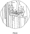
- the slot 26 converges to create narrow transverse width into which the delivery tube 20 is forced when the delivery tube is occluded, as shown in Fig. 6 .
- a trapezoid-shaped release tab 28 ( Figs. 4 , 5 and 10 ) extends forward from a front or distal end of the slide clamp 12 at a position which is adjacent to and distal of the non-occluding opening 24.
- a front door 30 is pivotally attached to a main body 32 of the infusion pump 10, as shown in Figs. 1 , 2 and 3 .
- a vertically-extending tubing channel 34 is located within a front panel 36 of the main pump body 32. The tubing channel 34 is accessible to receive a portion of the delivery tube 20 when the front door 30 is opened as shown in Figs. 2 and 3 .
- a conventional peristaltic pump 38 is located within the tubing channel 34 to compress and pinch the delivery tube 20 with the wavelike motion to move the fluid 14 through the delivery tube 20 when the door 30 is closed. The rate at which the peristaltic pump 38 operates controls the rate of flow of the fluid 14 through the delivery tube 20. The flow rate is programmed by attending medical personnel with the use of a conventional graphic interface 40 located on the exterior of the door 30.
- the peristaltic pump 38 prevents the gravity-induced free flow of fluid 14 through the delivery tube 20 when the infusion pump is not operating, so long as the door 30 is closed.
- a compression edge 42 of an internal occlusion clamp 43 compresses the delivery tube 20 against a stationary anvil 44 attached to the panel 36, thereby occluding the delivery tube when the door 30 is open.
- Closing the door 30 causes the internal occlusion clamp 43 to move the compression edge 42 away from the anvil 44 and open the delivery tube 20 to the fluid flow by operation of the peristaltic pump 38.
- the peristaltic pump 38 blocks the flow of fluid 14 through the delivery tube 20.
- a significant aspect of the present invention is using the slide clamp 12 as an actuator to release or open the internal occlusion clamp 43 while simultaneously moving the delivery tube 20 into the occluding slot 26, thereby pinching and occluding the delivery tube 20 with the slide clamp 12 when the occlusion clamp 43 is released or opened. In this manner, gravity-induced free flow of fluid 14 through the delivery tube 20 is prevented when the delivery tube 20 is released from the infusion pump.
- the anti-free flow requirements established by regulatory agencies and organizations are satisfied, by occluding the delivery tube with the slide clamp 12 at the same time that the slide clamp 12 is used as an actuator to release or open the internal occlusion clamp 43.
- the slide clamp 12 is manually positioned to insert the release tab 28 into an access opening 46 in the front panel 36 of the main body 32, as is understood by reference to Figs. 3-6 .
- Two tube supports 48 extend outward from the front panel 36 at locations above and below the access opening 46.
- Concave contact areas 50 ( Fig. 4 ) are formed in the forward portions of the tube supports 48 at locations transversely centered about the access opening 46.
- the release tab 28 causes the release tab 28 to release or open the internal occlusion clamp 43 while the contact areas 50 hold the delivery tube 20 stationary and force the delivery tube 20 into the occluding slot 26 of the slide clamp 12.
- the inward movement of the slide clamp 12 simultaneously forces the delivery tube 20 into the occluding slot 26 of the slide clamp 12 while the slide clamp 12 releases the internal occlusion clamp 43.
- the delivery tube 20 can be removed from the tubing channel 34 in the main body 32 of the infusion pump 10 because the compression edge 42 and the anvil 44 separate from one another. Gravity induced free flow of fluid through the removed delivery tube 20 is prevented by the occlusion from the slide clamp 12.
- Projections 52 are formed on opposite sides of the front edge of the release tab 28, as shown in Figs. 4 , 5 and 10 .
- the projections 52 fit into guide channels 54 formed in the tube supports 48 on opposite sides of the access opening 46.
- the projections 52 maintain the alignment of the release tab 28 within the access opening 46, to assure that the insertion of the slide clamp 12 positions the portion of the delivery tube 20 above and below the slide clamp in the contact areas 50. Such positioning assures that the further insertion of the slide clamp 12 into the access opening 46 moves the delivery tube into the occluding slot 26.
- the projections 52 also maintain the release tab 28 in position to release or open the internal occlusion clamp 43.
- a proximal or rear wedge-shaped portion 56 of the slide clamp 12 is significantly thicker than the remaining forward portions of the slide clamp 12.
- the thickness of the slide clamp 12 through the region of the occluding slot 26 and the release tab 28 is generally uniform.
- the wedge-shaped portion 56 increases in thickness beginning at a position approximately proximal of the proximal end of the occluding slot 26.
- the wedge-shaped rear portion 56 is intended to be grasped between the first and second fingers of the user, while the thumb of the user contacts the rear surface of the wedge-shaped portion 56.
- the delivery tube 20 is located in front of the first and second fingers, and the thumb pushes the slide clamp 12 into the access opening 46.
- the main body 32 of the infusion pump 10 may be held stationary by the user to counter the forces of pushing the slide clamp 12 to release the occlusion clamp 43 and to force the delivery tube 20 into the occluding slot 26 of the slide clamp 12.
- the peristaltic pump 38 is formed by a linear array of cam follower plungers 58 ( Fig. 8 ) located in the tubing channel 34 and by a spring-loaded backplate 60 ( Figs. 8 , 2 and 3 ) that is attached to an inner surface 62 of the door 30.
- the delivery tube 20 is loaded into the infusion pump 10 by positioning a portion of the delivery tube 20 within the tubing channel 34 as shown in Fig. 2 .
- the spring-loaded backplate 60 presses the delivery tube 20 against contact edges 63 of the cam follower plungers 58 when the door 30 is closed, as shown in Fig. 8 .
- the cam follower plungers 58 alternately and sequentially extend the contact edges 63 toward and away from the backplate 60 during operation of the peristaltic pump 38 to create an occlusion in the delivery tube 20 and move that occlusion sequentially through the peristaltic pump 38.
- One or more occlusions of the portion of the delivery tube within the peristaltic pump 38 exists due to this action.
- the peristaltic pump 38 continuously and controllably meters the fluid 14 through the delivery tube 20 toward the connector 22 and into the patient.
- Each contact edge 63 of each of the cam follower plunger 58 moves forward and backward in the tubing channel 34 while pressing against the delivery tube 20 due to the action of a cam lobe 64 attached eccentrically to a shaft 66, as understood from Fig. 8 .
- One cam lobe 64 is associated with each cam follower plunger 58.
- the cam lobe 64 is located within a rectangularly shaped opening 68 formed in the structure of each cam follower plunger 58.
- An electrical motor (not shown) rotates the shaft 66, causing the cam lobe 64 to rotate with the shaft 66.
- the cam lobe 64 rotates into contact with a front surface 70 of the opening 68 to push the cam follower plunger 58 forward with the contact edge 63 against the delivery tube 20.
- the eccentric surface of the cam lobe 64 push against a rear surface 72 of the opening 68, thereby moving the cam follower plunger 58 and the contact edge 63 rearwardly.
- the side surfaces 74 of the opening 68 may also contact the cam lobe 64 and cause the cam follower plungers 58 to pivot slightly from side to side. Attaching the separate cam lobes 64 at different rotationally displaced positions on the shaft 66 in sequence causes the wave-like sequential action of contact edges 63 of the cam follower plungers 58 against the delivery tube 20 from with rotation of the shaft 66.
- the spring loaded backplate 60 is confined within a retaining area 76 formed in the inner surface 62 of the door 30, as shown in Fig. 7 .
- Two or more springs 78 push the backplate 60 away from the door 30 and against a pair of retaining lips 80 which extend from the inner surface 62 and which form part of the retaining area 76.
- the backplate 60 withdraws into the door 30 from an extended position as shown in Figs. 2 , 3 and 8 , when enough pressure is exerted on the exterior face or working surface of the backplate 60 by the portion of the delivery tube 20 compressed by the contact edges 63 of the cam follower plungers 58, to overcome the force exerted by the springs 78.
- the spring loaded backplate 60 supplies sufficient force against the delivery tube 20 to allow the contact edges 63 to occlude the delivery tube 20 when each cam follower plunger 58 is in its forwardmost position.
- the door 30 of the infusion pump 10 must be closed for the peristaltic pump 38 to operate.
- a sensor (not shown) detects whether or not the door 30 is closed and allows the operation of the peristaltic pump 38 only when the door 30 is closed.
- At least one contact edge 63 of one cam follower plunger 58 is always occluding the delivery tube 20 when the door 30 is closed, whether or not the peristaltic pump 38 is operating. Since the delivery tube 20 is always occluded when the door 30 is closed, the fluid 14 is prevented from flowing freely by gravity through the delivery tube 20 when the door 30 is closed.
- the occlusion clamp 43 moves into a clamping or occluding position shown in Fig. 9 from an open or released position shown in Figs. 10 and 11 .
- the compression edge 42 of the occlusion clamp 43 presses the delivery tube 20 against the anvil 44 to occlude the delivery tube when the occlusion clamp 43 is in the clamping position.
- a blocking lip 82 extends from the compression edge 42 around the delivery tube 20 and across the gap between the compression edge 42 and the anvil 44 and slightly overlaps the anvil 44, as shown in Figs. 4 and 9 , to prevent the forcible removal of the delivery tube 20 from between the compression edge 42 and the anvil 44 when the occlusion clamp 43 is in the clamping position.
- the occlusion clamp 43 includes a lever 84 which pivots about a pivot point 86 to establish the clamping position ( Fig. 9 ) and the open position ( Figs. 10 and 11 ).
- a lever lock mechanism 88 ( Fig. 12 ) holds the lever 84 in the open position when the slide clamp 12 releases the occlusion clamp 43 when the door 30 of the infusion pump 10 is open.
- the lever 84 is biased into the clamping position by a bias spring 89 connected between an arm 90 of the lever 84 and a connection point 92 within the main body 32 of the infusion pump 10.
- Another arm 94 of the lever 84 extends on the opposite side of the pivot point 86 and locates the compression edge 42 at a position for interaction with the anvil 44.
- the other arm 94 also locates a release surface 96 ( Fig. 9 ) formed on the lever arm 94 at a location which is directly behind the access opening 46 ( Fig. 4 ) in the front panel 36 of the main body 32.
- the bias spring 89 forces the compression edge 42 toward the anvil 44 and forces the release surface 96 toward the access opening 46.
- the lever 84 is similar to a lever used in an internal occlusion clamp of a prior art infusion pump, except for the blocking lip 82 and the release surface 96.
- the blocking lip 82 is not used. Without the blocking lip 82, the delivery tube can be forcibly removed from between the compression edge 42 and the anvil 44.
- the release surface 96 does not exist but instead a portion of the lever 84 continues forward and extends outside of the front panel 36. The portion of the lever which extends forward from the front panel terminates in a contact, which is manually depressed by finger pressure of the user to open or release the internal occlusion clamp after the door has been opened.
- the lever lock mechanism 88 includes a plunger 98 which moves between a retracted position shown in Fig. 11 and an extended position shown in Figs. 9 and 10 .
- a spring 100 extends from within a recess in the plunger 98 to contact a surface of the main body. The spring 100 biases the plunger 98 toward the lever arm 94.
- a retaining edge 102 of the plunger 98 extends in front of and past the release surface 96 on the lever arm 94. The retaining edge 102 of the plunger 98 holds the lever 84 to establish the open position of the occlusion clamp 43.
- the release tab 28 of the slide clamp 12 contacts the release surface 96 of the lever arm 94 through the access opening 46, and further insertion force applied to the slide clamp 12 pivots the lever 84 sufficiently so that the retaining edge 102 of the plunger 98 extends in front of the release surface 96. With the plunger 98 in the extended position with the retaining edge 102 overlapping the release surface 96, the lever 84 is pivoted so that the occlusion clamp 43 is in the open position.
- the bias spring 89 supplies enough pivoting force on the arm 84 to maintain sufficient frictional contact between the release surface 96 and the retaining edge 102 to hold the occlusion clamp 43 in the open position.
- the occlusion clamp 43 can only be released by closing the door 30. Releasing the occlusion clamp 43 is accomplished by moving the plunger 98 to a retracted position where the retaining edge 102 is withdrawn from contact with the release surface 96, thereby allowing the lever arm 94 to pivot slightly forward.
- Moving the plunger 98 to the retracted position is accomplished by two release projections 104 which protrude from the inner surface 62 of the door 30 ( Figs. 2 and 3 ).
- the door release projections 104 extend through openings 108 in the front panel 36 of the main body 32 and contact upper and lower portions of a slide pin 110 which extends vertically upward and downward from the plunger 98 ( Figs. 11 and 12 ). Ramp surfaces of the door release projections 104 contact the slide pin 110, and move the plunger to the retracted position by camming action as the door 30 closes.
- a door release tab 114 extends from the inner surface 62 of the door 30 into the access opening 46 when the door is closed.
- the door release tab 114 contacts the release surface 96 of the lever arm 94, and holds the lever 84 in the position to release and open the occlusion clamp 43 when the door 30 is closed, as shown in Figs. 10 and 11 .
- the retaining edge 102 of the plunger 98 is moved laterally to the side of the release surface 96, so that upon opening the door 30, the plunger 98 does not prevent the lever 84 from pivoting to the occluding position.
- the plunger 98 of the lever lock mechanism 88 does not prevent the lever 84 from pivoting into the position to occlude the delivery tube 20 after the door 30 has been closed and when the door is opened.
- the plunger 98 of the lever lock mechanism 88 holds the lever 84 in the open position only after the slide clamp 12 has been used as an actuator to release the occlusion clamp 43 to its open position.
- a door latch lever 116 is pivotally connected to the door 30, as shown in Figs. 1-3 .
- the door latch lever 116 locks the door 30 to the body 32 when the lever 116 is pivoted into the closed position ( Fig. 1 ). Pivoting the door latch lever 116 in the opposite direction unlocks the door 30 and allows it to open to the open position ( Fig. 2 ).
- An arc shaped portion 118 of the door latch lever 116 extends into a recess area 120 formed on a front panel 36 of the main body 32.
- the arc shaped portion 118 engages a latch pin 122 which extends across a portion of the recess area 120.
- Pivoting movement of the door latch lever 116 causes the arc shaped portion 118 to move relative to the latch pin 122 and pull the door 30 firmly against the front panel 36 of the main body 32. Pivoting the door latch lever 116 in the opposite direction opens the door by releasing the arc shaped portion 118 from the latch pin 122.
- the slide clamp 12 is orientated horizontally and positioned such that the release tab 28 of the slide clamp 12 is adjacent to the access opening 46, as understood from Figs. 4 and 5 .
- the projections 52 of the slide clamp 12 extend into the guide channels 54 ( Fig. 5 ).
- the release tab 28 is forced into contact with the release surface 96 of the lever arm 94 while portions of the delivery tube 20 immediately above and below the slide clamp 12 move into contact with the concave contact areas 50 ( Fig. 5 ) of the tube supports 48, as shown in Figs. 6 , 10 and 11 .
- the thick rear wedge-shaped portion 56 of the slide clamp 12 is pushed by force from the users thumb while the slide clamp 12 is maintained in alignment between the tube supports 48 by the projections 52 in the guide channels 54.
- the release tab 28 of the slide clamp 12 moves forward while in contact with the release surface 96 of the lever arm 94, the lever 84 pivots into the position where the retaining edge 102 of the plunger 98 extends in front of and overlaps with the release surface 96 to thereby hold the lever 84 and establish the open position of the occlusion clamp 43 simultaneously while the portion of the delivery tube 20 within the slide clamp 12 is forced from the non-occluding opening 24 into the occluding slot 26.
- the simultaneous occurrence of these two events effectively maintains, and transfers, the location of the occlusion from the occlusion clamp 43 to the slide clamp 12.
- any further use of the delivery tube will require the user to manually move the slide clamp 12 relative to the delivery tube 20 so that the delivery tube extends through the non-occluding opening 24. Even if the delivery tube is inserted into the infusion pump and the infusion pump is operated, there will be no fluid flow through the delivery tube until the delivery tube 20 is moved into the non-occluding opening 24 of the slide clamp 12. This requirement establishes the necessity for an additional safety-related manual action before fluid will flow through the delivery tube.
- the infusion pump 10 as shown and described in relation to this invention is simpler in operation and construction than previously known anti-free flow infusion pumps.
- the infusion pump 10 and slide clamp 12 combination is also less costly to manufacture, and allows their use together in the manner which makes it relatively easy and straightforward to train medical personnel in the proper and safe use of the equipment.
Landscapes
- Health & Medical Sciences (AREA)
- Heart & Thoracic Surgery (AREA)
- Hematology (AREA)
- Engineering & Computer Science (AREA)
- Anesthesiology (AREA)
- Biomedical Technology (AREA)
- Life Sciences & Earth Sciences (AREA)
- Animal Behavior & Ethology (AREA)
- General Health & Medical Sciences (AREA)
- Public Health (AREA)
- Veterinary Medicine (AREA)
- Pulmonology (AREA)
- Vascular Medicine (AREA)
- Infusion, Injection, And Reservoir Apparatuses (AREA)
Claims (9)
- Infusionspumpe (10) zur Nutzung mit einer Gleitklemme (12) nach Anspruch 7 und mit einer internen Okklusionsklemme (43) zum Verhindern eines freien Fließens eines medizinischen Fluids (14) durch einen Abgabeschlauch (20) eines Infusionsschlauchsatzes (16), der mit der Infusionspumpe (10) verwendet wird, um den Fluss des Fluids (14), welches an einen Patienten abgegeben wird, zu regulieren, wobei die interne Okklusionsklemme (43) eine okkludierende Position zum Okkludieren eines ersten Teils des Abgabeschlauchs (20) in einem Schlauchkanal (34) der Infusionspumpe (10) aufweist sowie eine nichtokkludierende Position zum Ermöglichen einer Fluidbewegung durch den Abgabeschlauch (20), wenn der erste Teil des Abgabeschlauchs (20) für den Nutzer der Infusionspumpe (10) nicht zugänglich ist, wobei die interne Okklusionsklemme (43) einen beweglichen Freigabemechanismus (96) aufweist, durch den die interne Okklusionsklemme (43) von der okkludierenden Position zu der nichtokkludierenden Position bewegbar ist, wobei die Infusionspumpe (10) weiterhin eine Zugangsöffnung (46) aufweist, durch die die Okklusionsklemme (43) aus der okkludierenden Position zu der nichtokkludierenden Position bewegbar ist, wobei der Schlauchsatz (16) die Gleitklemme (12) enthält, welche mit einem zweiten Teil des Abgabeschlauchs (20) verbunden ist, wobei die Gleitklemme (12) eine nichtokkludierende Öffnung (24) aufweist, die den Abgabeschlauch (20) nicht okkludiert, wenn der Abgabeschlauch in der nichtokkludierenden Öffnung (24) angeordnet ist, und auch eine okkludierende Öffnung (26) aufweist, die den Abgabeschlauch (20) okkludiert, wenn der Abgabeschlauch in der okkludierenden Öffnung angeordnet ist.
- Infusionspumpe (10) nach Anspruch 1, wobei die Infusionspumpe (10) weiterhin umfasst:eine Pumpvorrichtung (38), die sich mit dem Schlauchkanal (34) zum Bewegen des Fluids (14) durch den Abgabeschlauch (20) in Kommunikation befindet;einen Gegenhalter (44), der an einer Seite des Schlauchkanals (34) angebracht ist;einen Schwenkhebel (84) der Okklusionsklemme (43) mit einer Kompressionskante (42), die sich von der Seite des Schlauchkanals (34) gegenüber dem Gegenhalter (44) in Nachbarschaft zu dem Gegenhalter (44) bewegt, wenn sich die interne Okklusionsklappe (43) in der okkludierenden Position befindet, und welche sich weg von der Nachbarschaft zu dem Gegenhalter (44) bewegt, wenn sich die interne Okklusionsklemme (43) in der nichtokkludierenden Position befindet, wobei der Hebel (84) eine Freigabeoberfläche (96) aufweist, die in der Zugangsöffnung (46) angeordnet ist; undeinen Hebelverriegelungsmechanismus (88), um den Hebel (84) lösbar in der nichtokkludierenden Position der internen Okklusionsklemme (43) zu halten; und wobei:
das Freigabestück (28) der Gleitklemme (12) die Freigabeoberfläche (96) des Hebels (84) kontaktiert und die Okklusionsklemme (43) aus der okkludierenden Position in die nichtokkludierende Position mit einführender Bewegung der Gleitklemme (12) in die Zugangsöffnung (46) bewegt. - Infusionspumpe (10) nach Anspruch 2, weiterhin umfassend:eine Tür (30), die zwischen einer geschlossenen Position, welche einen Zugriff auf den ersten Teil des Abgabeschlauchs (20) in dem Schlauchkanal (34) verhindert, und einer offenen Position bewegbar ist, welche einen Zugriff auf den ersten Teil des Abgabeschlauchs (20) in dem Schlauchkanal (34) zur Verfügung stellt, undein Türfreigabestück (114), welches von der Tür (30) in die Zugangsöffnung (46) vorsteht, um die Freigabeoberfläche (96) des Schwenkhebels (84) zu kontaktieren und die Okklusionsklemme (43) von der okkludierenden Position in die nichtokkludierende Position zu bewegen, wenn die Tür (30) geschlossen wird.
- Infusionspumpe (10) nach Anspruch 2 oder 3, wobei:
der Schwenkhebel (84) weiterhin eine Blockierlippe (82) enthält, die sich von der Kompressionskante (42) zu dem Gegenhalter (44) erstreckt, um ein Entfernen des Abgabeschlauchs (20) zwischen der Kompressionskante (42) und dem Gegenhalter (44) zu blockieren, wenn sich die interne Okklusionsklemme (43) in der okkludierenden Position befindet. - Infusionspumpe (10) nach Anspruch 2, 3 oder 4, wobei:der Schlauchträger (48) einen Führungskanal (54) enthält, welcher sich in Richtung auf die Zugangsöffnung (46) erstreckt; unddie Gleitklemme (12) einen Vorsprung (52) benachbart zu dem Freigabestück (28) enthält, welche sich in dem Führungskanal (54) während einer einführenden Bewegung der Gleitklemme bewegt.
- Infusionspumpe (10) nach Anspruch 2, 3, 4 oder 5, wobei der Hebelverriegelungsmechanismus (88) weiterhin umfasst:einen Stößel (98) mit einer Haltekante (102), die transversal bewegbar ist, um mit der Freigabeoberfläche (96) des Schwenkhebels (84) zu überlappen;einen Gleitstift (110), der sich transversal von dem Stößel (98) erstreckt; und wobei die Infusionspumpe (10) weiterhin umfasst:
eine Freigabeöffnung (108) benachbart zu dem Gleitstift (110), durch die Zugriff auf den Gleitstift zu erreichen ist; und wobei:
die Tür (30) weiterhin einen Türfreigabevorsprung (104) enthält, der von der Tür in die Freigabeöffnung (108) vorsteht, um den Gleitstift (110) zu kontaktieren und den Stößel (98) zu bewegen, um die Haltekante (102) von der überlappenden Beziehung mit der Freigabeoberfläche des Schwenkhebels (84) zu trennen und um der internen Okklusionsklemme (43) zu ermöglichen, die nichtokkludierende Position einzunehmen, wenn die Tür (30) geschlossen wird. - Gleitklemme (12) zur Nutzung mit der Infusionspumpe (10) nach Anspruch 1 zum selektiven Okkludieren eines Abgabeschlauchs (20), der sich durch die Infusionspumpe (10) erstreckt, welche eine interne Okklusionsklemme (43) mit einem Freigabemechanismus (96) aufweist, um die interne Okklusionsklemme (43) zwischen einer okkludierenden Position zum Okkludieren des Abgabeschlauchs (20) und einer nichtokkludierenden Position zum Öffnen des Abgabeschlauchs zu bewegen, wobei die Gleitklemme (12) geeignet ist, in einer Zugangsöffnung (46) der Infusionspumpe aufgenommen zu werden, wobei die Gleitklemme (12) einen Körper mit einer Länge in einer longitudinalen Dimension aufweist, die sich von einem proximalen Ende zu einem distalen Ende erstreckt, wobei der Körper eine Breite in einer lateralen Dimension aufweist, senkrecht zu der longitudinalen Dimension, wobei die Breite des Körpers geringer ist als die Länge des Körpers, wobei der Körper eine Höhe in einer Dimension senkrecht zu der longitudinalen und der lateralen Dimension aufweist, wobei die Höhe des Körpers geringer ist als die Breite des Körpers,wobei der Körper eine nichtokkludierende Öffnung (24) definiert, die eine Breite in der lateralen Dimension aufweist, die nicht ausreicht, um den Schlauch (20) auf ein Bewegen des Schlauchs in die nichtokkludierende Öffnung (24) zu quetschen und zu okkludieren,wobei der Körper weiterhin eine okkludierende Öffnung (26) definiert, die sich proximal von der nichtokkludierenden Öffnung (24) erstreckt, wobei die okkludierende Öffnung (26) eine Breite in der lateralen Dimension aufweist, die ausreichend ist, um den Schlauch auf eine Bewegung des Schlauchs in die okkludierende Öffnung (26) zu quetschen und zu okkludieren;dadurch gekennzeichnet, dass:ein trapezoidförmiges Freigabestück (28) an dem distalen Ende des Körpers angeordnet ist, das eine Breite aufweist, die geringer ist als die Breite des Körpers proximal von dem Freigabestück (28), wobei das Freigabestück geeignet ist, den Freigabemechanismus (96) zu kontaktieren und die interne Okklusionsklemme von der okkludierenden Position zu der nichtokkludierenden Position auf eine einführende Bewegung der Gleitklemme in die Zugangsöffnung (46) zu bewegen; undein keilförmiger Teil (56) an dem proximalen Ende des Körpers ausgebildet ist, wobei der keilförmige Teil (56) sich proximal von dem proximalen Ende der okkludierenden Öffnung (26) erstreckt und in seiner Höhe von dem proximalen Ende der okkludierenden Öffnung (26) zu dem proximalen Ende des Körpers zunehmend größer wird, wobei der keilförmige Teil geeignet ist, zwischen einem ersten und einem zweiten Finger eines Nutzers ergriffen zu werden, während ein Daumen des Nutzers eine proximale Oberfläche des keilförmigen Teils kontaktiert, während der Nutzer die Gleitklemme (12) während eines Einführens in die Zugangsöffnung (46) manipuliert, um die interne Okklusionsklemme (43) zu bewegen;sich der keilförmige Teil in seiner Höhe um einen Betrag vergrößert, der wenigstens zweimal der Höhe des Körpers an dem Ort der okkludierenden und der nichtokkludierenden Öffnung (24, 26) hat; unddie Höhe des keilförmigen Teils an dem proximalen Ende größer ist als
die Höhe des Körpers an dem distalen Ende. - Gleitklemme (12) nach Anspruch 7, weiterhin umfassend:
einen Vorsprung (52), der sich in der Höhendimension über dem Teil des Körpers, in dem die okkludierende und die nichtokkludierende Öffnung (24, 26) definiert sind, erstreckt, wobei der Vorsprung (52) sich von dem Körper an einem Ort distal von der nichtokkludierenden Öffnung (24) und proximal von dem Freigabestück (28) erstreckt, wobei der Vorsprung (52) geeignet ist, sich innerhalb eines Führungskanals (54) auf eine einführende Bewegung der Gleitklemme in die Zugangsöffnung (46) zu bewegen. - Infusionsschlauchset (16) mit einer Gleitklemme (12) nach Anspruch 7 oder 8, umfassend:eine komprimierbare Fluidtasche (18), die ein Inneres zum Aufnehmen eines Fluids (14) umfasst, welches einem Patienten zu infundieren ist;einen Abgabeschlauch (20) mit einem ersten Ende, das mit der Fluidtasche (18) verbunden ist, und einem zweiten Ende, mit einem Verbinder (22) zur Abgabe des Fluids (14), wobei der Abgabeschlauch (20) das Fluid von der Fluidtasche (18) zu dem Verbinder (22) führt; und wobeider Abgabeschlauch sich durch wenigstens eine von der okkludierenden und der nichtokkludierenden Öffnung (24, 26) in der Gleitklemme (12) erstreckt.
Applications Claiming Priority (1)
| Application Number | Priority Date | Filing Date | Title |
|---|---|---|---|
| US12/852,116 US8465464B2 (en) | 2010-08-06 | 2010-08-06 | Infusion pump and slide clamp apparatus and method |
Publications (2)
| Publication Number | Publication Date |
|---|---|
| EP2415498A1 EP2415498A1 (de) | 2012-02-08 |
| EP2415498B1 true EP2415498B1 (de) | 2019-01-02 |
Family
ID=44532536
Family Applications (1)
| Application Number | Title | Priority Date | Filing Date |
|---|---|---|---|
| EP11006387.2A Active EP2415498B1 (de) | 2010-08-06 | 2011-08-03 | Infusionspumpe und Gleitklemmvorrichtung und -verfahren |
Country Status (5)
| Country | Link |
|---|---|
| US (3) | US8465464B2 (de) |
| EP (1) | EP2415498B1 (de) |
| AU (1) | AU2011203150B9 (de) |
| CA (1) | CA2744609C (de) |
| MX (1) | MX2011007884A (de) |
Families Citing this family (95)
| Publication number | Priority date | Publication date | Assignee | Title |
|---|---|---|---|---|
| US9028691B2 (en) | 2007-02-27 | 2015-05-12 | Deka Products Limited Partnership | Blood circuit assembly for a hemodialysis system |
| US8992517B2 (en) | 2008-04-29 | 2015-03-31 | Virginia Tech Intellectual Properties Inc. | Irreversible electroporation to treat aberrant cell masses |
| US10272178B2 (en) | 2008-04-29 | 2019-04-30 | Virginia Tech Intellectual Properties Inc. | Methods for blood-brain barrier disruption using electrical energy |
| US9198733B2 (en) | 2008-04-29 | 2015-12-01 | Virginia Tech Intellectual Properties, Inc. | Treatment planning for electroporation-based therapies |
| US11272979B2 (en) | 2008-04-29 | 2022-03-15 | Virginia Tech Intellectual Properties, Inc. | System and method for estimating tissue heating of a target ablation zone for electrical-energy based therapies |
| US9867652B2 (en) | 2008-04-29 | 2018-01-16 | Virginia Tech Intellectual Properties, Inc. | Irreversible electroporation using tissue vasculature to treat aberrant cell masses or create tissue scaffolds |
| US11254926B2 (en) | 2008-04-29 | 2022-02-22 | Virginia Tech Intellectual Properties, Inc. | Devices and methods for high frequency electroporation |
| US10702326B2 (en) | 2011-07-15 | 2020-07-07 | Virginia Tech Intellectual Properties, Inc. | Device and method for electroporation based treatment of stenosis of a tubular body part |
| US10245098B2 (en) | 2008-04-29 | 2019-04-02 | Virginia Tech Intellectual Properties, Inc. | Acute blood-brain barrier disruption using electrical energy based therapy |
| US9283051B2 (en) | 2008-04-29 | 2016-03-15 | Virginia Tech Intellectual Properties, Inc. | System and method for estimating a treatment volume for administering electrical-energy based therapies |
| US10238447B2 (en) | 2008-04-29 | 2019-03-26 | Virginia Tech Intellectual Properties, Inc. | System and method for ablating a tissue site by electroporation with real-time monitoring of treatment progress |
| US8632534B2 (en) | 2009-04-03 | 2014-01-21 | Angiodynamics, Inc. | Irreversible electroporation (IRE) for congestive obstructive pulmonary disease (COPD) |
| US11638603B2 (en) | 2009-04-09 | 2023-05-02 | Virginia Tech Intellectual Properties, Inc. | Selective modulation of intracellular effects of cells using pulsed electric fields |
| US11382681B2 (en) | 2009-04-09 | 2022-07-12 | Virginia Tech Intellectual Properties, Inc. | Device and methods for delivery of high frequency electrical pulses for non-thermal ablation |
| US8903488B2 (en) | 2009-05-28 | 2014-12-02 | Angiodynamics, Inc. | System and method for synchronizing energy delivery to the cardiac rhythm |
| US9895189B2 (en) | 2009-06-19 | 2018-02-20 | Angiodynamics, Inc. | Methods of sterilization and treating infection using irreversible electroporation |
| US9789247B2 (en) | 2011-12-21 | 2017-10-17 | Deka Products Limited Partnership | Syringe pump, and related method and system |
| US9677555B2 (en) | 2011-12-21 | 2017-06-13 | Deka Products Limited Partnership | System, method, and apparatus for infusing fluid |
| US9151646B2 (en) | 2011-12-21 | 2015-10-06 | Deka Products Limited Partnership | System, method, and apparatus for monitoring, regulating, or controlling fluid flow |
| US9744300B2 (en) | 2011-12-21 | 2017-08-29 | Deka Products Limited Partnership | Syringe pump and related method |
| US9295778B2 (en) | 2011-12-21 | 2016-03-29 | Deka Products Limited Partnership | Syringe pump |
| US9700368B2 (en) | 2010-10-13 | 2017-07-11 | Angiodynamics, Inc. | System and method for electrically ablating tissue of a patient |
| WO2012088149A2 (en) | 2010-12-20 | 2012-06-28 | Virginia Tech Intellectual Properties, Inc. | High-frequency electroporation for cancer therapy |
| US9078665B2 (en) | 2011-09-28 | 2015-07-14 | Angiodynamics, Inc. | Multiple treatment zone ablation probe |
| US9376655B2 (en) | 2011-09-29 | 2016-06-28 | Life Technologies Corporation | Filter systems for separating microcarriers from cell culture solutions |
| CN103930160B (zh) * | 2011-11-16 | 2017-05-03 | 费森尤斯维亚尔两合公司 | 管泵、管夹、输注组件以及包括管泵和管夹的系统 |
| US10722645B2 (en) | 2011-12-21 | 2020-07-28 | Deka Products Limited Partnership | Syringe pump, and related method and system |
| US12544501B2 (en) * | 2011-12-21 | 2026-02-10 | Deka Products Limited Partneship | Flow meter having a valve |
| US10488848B2 (en) | 2011-12-21 | 2019-11-26 | Deka Products Limited Partnership | System, method, and apparatus for monitoring, regulating, or controlling fluid flow |
| US10088346B2 (en) | 2011-12-21 | 2018-10-02 | Deka Products Limited Partnership | System, method, and apparatus for monitoring, regulating, or controlling fluid flow |
| US11217340B2 (en) | 2011-12-21 | 2022-01-04 | Deka Products Limited Partnership | Syringe pump having a pressure sensor assembly |
| US9724466B2 (en) | 2011-12-21 | 2017-08-08 | Deka Products Limited Partnership | Flow meter |
| US9675756B2 (en) | 2011-12-21 | 2017-06-13 | Deka Products Limited Partnership | Apparatus for infusing fluid |
| US9746093B2 (en) | 2011-12-21 | 2017-08-29 | Deka Products Limited Partnership | Flow meter and related system and apparatus |
| US9372486B2 (en) | 2011-12-21 | 2016-06-21 | Deka Products Limited Partnership | System, method, and apparatus for monitoring, regulating, or controlling fluid flow |
| US9435455B2 (en) | 2011-12-21 | 2016-09-06 | Deka Products Limited Partnership | System, method, and apparatus for monitoring, regulating, or controlling fluid flow |
| US9746094B2 (en) | 2011-12-21 | 2017-08-29 | Deka Products Limited Partnership | Flow meter having a background pattern with first and second portions |
| US10563681B2 (en) | 2011-12-21 | 2020-02-18 | Deka Products Limited Partnership | System, method, and apparatus for clamping |
| US9856990B2 (en) | 2011-12-21 | 2018-01-02 | Deka Products Limited Partnership | Flow metering using a difference image for liquid parameter estimation |
| US10561787B2 (en) | 2011-12-21 | 2020-02-18 | Deka Products Limited Partnership | Syringe pump and related method |
| US9414881B2 (en) | 2012-02-08 | 2016-08-16 | Angiodynamics, Inc. | System and method for increasing a target zone for electrical ablation |
| US9364655B2 (en) | 2012-05-24 | 2016-06-14 | Deka Products Limited Partnership | Flexible tubing occlusion assembly |
| US9759343B2 (en) | 2012-12-21 | 2017-09-12 | Deka Products Limited Partnership | Flow meter using a dynamic background image |
| US20140271246A1 (en) * | 2013-03-14 | 2014-09-18 | Carefusion 303, Inc. | Cooperation of platen and pump cassette for pump device |
| US10226571B2 (en) | 2013-03-14 | 2019-03-12 | Carefusion 303, Inc. | Pump segment placement |
| US20140271247A1 (en) * | 2013-03-14 | 2014-09-18 | Carefusion 303, Inc. | Infusion pump configured to engage a sensor with tubing |
| US9968739B2 (en) | 2013-03-14 | 2018-05-15 | Carefusion 303, Inc. | Rotary valve for a disposable infusion set |
| US9468714B2 (en) | 2013-03-14 | 2016-10-18 | Carefusion 303, Inc. | Memory and identification associated with IV set |
| US9360124B2 (en) | 2013-03-15 | 2016-06-07 | Cook Medical Technologies Llc | Bi-directional valve device for selective control of fluid flow through multiple converging paths |
| USD762850S1 (en) * | 2013-04-23 | 2016-08-02 | Covidien Lp | Cassette |
| USD735319S1 (en) | 2013-06-11 | 2015-07-28 | Deka Products Limited Partnership | Medical pump |
| USD736370S1 (en) | 2013-06-11 | 2015-08-11 | Deka Products Limited Partnership | Medical pump |
| USD767756S1 (en) | 2013-06-11 | 2016-09-27 | Deka Products Limited Partnership | Medical pump |
| USD751690S1 (en) | 2013-11-06 | 2016-03-15 | Deka Products Limited Partnership | Apparatus to control fluid flow through a tube |
| USD751689S1 (en) * | 2013-11-06 | 2016-03-15 | Deka Products Limited Partnership | Apparatus to control fluid flow through a tube |
| USD749206S1 (en) * | 2013-11-06 | 2016-02-09 | Deka Products Limited Partnership | Apparatus to control fluid flow through a tube |
| USD752209S1 (en) * | 2013-11-06 | 2016-03-22 | Deka Products Limited Partnership | Apparatus to control fluid flow through a tube |
| USD745661S1 (en) | 2013-11-06 | 2015-12-15 | Deka Products Limited Partnership | Apparatus to control fluid flow through a tube |
| USD760782S1 (en) | 2013-12-20 | 2016-07-05 | Deka Products Limited Partnership | Display screen of a medical pump with a graphical user interface |
| USD760888S1 (en) * | 2013-12-20 | 2016-07-05 | Deka Products Limited Partnership | Medical pump |
| CA3175252A1 (en) | 2014-02-21 | 2015-08-27 | Deka Products Limited Partnership | Syringe pump having a pressure sensor assembly |
| CN112807074A (zh) | 2014-05-12 | 2021-05-18 | 弗吉尼亚暨州立大学知识产权公司 | 电穿孔系统 |
| US12114911B2 (en) | 2014-08-28 | 2024-10-15 | Angiodynamics, Inc. | System and method for ablating a tissue site by electroporation with real-time pulse monitoring |
| EP3193975B1 (de) | 2014-09-18 | 2022-07-06 | DEKA Products Limited Partnership | Vorrichtung und verfahren zur infusion eines fluids durch ein rohr mittels geeigneter erwärmung des rohrs |
| US10694972B2 (en) | 2014-12-15 | 2020-06-30 | Virginia Tech Intellectual Properties, Inc. | Devices, systems, and methods for real-time monitoring of electrophysical effects during tissue treatment |
| USD803386S1 (en) | 2015-02-10 | 2017-11-21 | Deka Products Limited Partnership | Syringe medical pump |
| USD801519S1 (en) | 2015-02-10 | 2017-10-31 | Deka Products Limited Partnership | Peristaltic medical pump |
| USD805183S1 (en) | 2015-02-10 | 2017-12-12 | Deka Products Limited Partnership | Medical pump |
| USD803387S1 (en) | 2015-02-10 | 2017-11-21 | Deka Products Limited Partnership | Syringe medical pump |
| EP3302681A4 (de) * | 2015-06-01 | 2019-03-13 | Smiths Medical ASD, Inc. | Infusatschlauchklemmensysteme für infusionspumpen |
| DE102015117493A1 (de) | 2015-10-14 | 2017-04-20 | B. Braun Melsungen Ag | Medizinische Pumpe mit Schlauchklemmenaufnahme, Schlauchklemme sowie System aus beiden |
| USD905848S1 (en) | 2016-01-28 | 2020-12-22 | Deka Products Limited Partnership | Apparatus to control fluid flow through a tube |
| EP4335471A3 (de) | 2016-01-28 | 2024-08-21 | DEKA Products Limited Partnership | Vorrichtung zur überwachung, regelung oder steuerung eines fluidstroms |
| USD854145S1 (en) | 2016-05-25 | 2019-07-16 | Deka Products Limited Partnership | Apparatus to control fluid flow through a tube |
| US10167861B2 (en) * | 2016-05-26 | 2019-01-01 | Namiki Precision Singapore Pte. Ltd. | Infusion pump |
| US11167081B2 (en) | 2016-06-16 | 2021-11-09 | Smiths Medical Asd, Inc. | Assemblies and methods for infusion pump system administration sets |
| US10905492B2 (en) | 2016-11-17 | 2021-02-02 | Angiodynamics, Inc. | Techniques for irreversible electroporation using a single-pole tine-style internal device communicating with an external surface electrode |
| DE102017103852A1 (de) * | 2017-02-24 | 2018-08-30 | B. Braun Melsungen Aktiengesellschaft | Sicherheits-Fluidleitungssystem für eine medizintechnische Schlauchpumpe, Schlauchpumpe sowie Einheit daraus |
| DE102017116106A1 (de) * | 2017-07-18 | 2019-01-24 | B. Braun Melsungen Ag | Vorrichtung und Verfahren zum Öffnen und Schließen einer Infusionsschlauchklemme |
| AU2018302257A1 (en) | 2017-07-19 | 2020-01-30 | Smiths Medical Asd, Inc. | Housing arrangements for infusion pumps |
| DE102017122647A1 (de) * | 2017-09-28 | 2019-03-28 | B. Braun Melsungen Ag | Schlauchklemme und volumetrische Pumpe mit Schlauchklemme |
| US11607537B2 (en) | 2017-12-05 | 2023-03-21 | Virginia Tech Intellectual Properties, Inc. | Method for treating neurological disorders, including tumors, with electroporation |
| US10759584B2 (en) | 2018-03-02 | 2020-09-01 | Life Technologies Corporation | System for port and tube holder assembly attachment device and methods of use |
| US11311329B2 (en) | 2018-03-13 | 2022-04-26 | Virginia Tech Intellectual Properties, Inc. | Treatment planning for immunotherapy based treatments using non-thermal ablation techniques |
| US12390262B2 (en) | 2018-03-13 | 2025-08-19 | Virginia Tech Intellectual Properties, Inc. | Treatment planning system for immunotherapy enhancement via non-thermal ablation |
| US11925405B2 (en) | 2018-03-13 | 2024-03-12 | Virginia Tech Intellectual Properties, Inc. | Treatment planning system for immunotherapy enhancement via non-thermal ablation |
| USD917045S1 (en) * | 2018-08-16 | 2021-04-20 | Deka Products Limited Partnership | Slide clamp |
| KR102841201B1 (ko) | 2018-08-16 | 2025-08-01 | 데카 프로덕츠 리미티드 파트너쉽 | 의료용 펌프 |
| US11950835B2 (en) | 2019-06-28 | 2024-04-09 | Virginia Tech Intellectual Properties, Inc. | Cycled pulsing to mitigate thermal damage for multi-electrode irreversible electroporation therapy |
| US12214189B2 (en) | 2019-07-24 | 2025-02-04 | Virginia Tech Intellectual Properties, Inc. | Fourier analysis spectroscopy for monitoring tissue impedance changes and treatment outcome during electroporation-based-therapies |
| WO2021021596A1 (en) | 2019-07-26 | 2021-02-04 | Deka Products Limited Partnership | Apparatus for monitoring, regulating, or controlling fluid flow |
| USD964563S1 (en) | 2019-07-26 | 2022-09-20 | Deka Products Limited Partnership | Medical flow clamp |
| USD1004412S1 (en) | 2019-08-16 | 2023-11-14 | Deka Products Limited Partnership | Slide clamp assembly |
| US12485279B2 (en) | 2020-11-25 | 2025-12-02 | Virginia Tech Intellectual Properties, Inc. | Methods for modulating temporal infrastructure of pulsed electric fields |
| WO2023055716A1 (en) | 2021-09-29 | 2023-04-06 | Medical Components, Inc. | Locking slide clamp |
Family Cites Families (26)
| Publication number | Priority date | Publication date | Assignee | Title |
|---|---|---|---|---|
| US3374509A (en) | 1966-05-27 | 1968-03-26 | Bard Inc C R | Clamp |
| US4155362A (en) | 1976-01-26 | 1979-05-22 | Baxter Travenol Laboratories, Inc. | Method and apparatus for metered infusion of fluids |
| US4460358A (en) | 1980-11-07 | 1984-07-17 | Ivac Corporation | Combined load and latch mechanism for fluid flow control apparatus |
| US4586691A (en) | 1985-05-13 | 1986-05-06 | Warner-Lambert Company | Safety slide clamp |
| US4689043A (en) | 1986-03-19 | 1987-08-25 | Imed Corporation | IV tube activator |
| US4818190A (en) | 1987-12-01 | 1989-04-04 | Pacesetter Infusion, Ltd. | Cassette loading and latching apparatus for a medication infusion system |
| US5017192A (en) | 1989-10-20 | 1991-05-21 | Minnesota Mining And Manufacturing Company | Free flow prevention system for infusion pump |
| US5254088A (en) * | 1990-02-02 | 1993-10-19 | Ep Technologies, Inc. | Catheter steering mechanism |
| JPH0693916B2 (ja) | 1990-10-31 | 1994-11-24 | テルモ株式会社 | 輸液ポンプ |
| CA2064134A1 (en) | 1991-04-23 | 1992-10-24 | Gary A. Thill | Free flow prevention system for infusion pump |
| US5290239A (en) | 1991-09-26 | 1994-03-01 | Baxter International, Inc. | Intravenous tube safety apparatus |
| US5437635A (en) | 1992-05-06 | 1995-08-01 | Mcgaw, Inc. | Tube flow limiter, safety flow clip, and tube pincher mechanism |
| US5290238A (en) | 1992-06-10 | 1994-03-01 | Imed Corporation | Self priming tubing set for an infusion device |
| US5401256A (en) | 1994-01-14 | 1995-03-28 | Minnesota Mining And Manufacturing Company | Flexible clamp for use in IV tubing set |
| US5453098A (en) | 1994-05-09 | 1995-09-26 | Imed Corporation | Two step IV fluid flow stop |
| US6261262B1 (en) | 1997-06-12 | 2001-07-17 | Abbott Laboratories | Pump with anti-free flow feature |
| US5868712A (en) | 1997-06-12 | 1999-02-09 | Abbott Laboratories | Pump with door-mounted mechanism for positioning tubing in the pump housing |
| US6117115A (en) * | 1998-10-12 | 2000-09-12 | B. Braun Medical, Inc. | Medical tubing slide clamp device for determining proper tubing size and functional characteristics |
| JP2000237308A (ja) | 1999-02-22 | 2000-09-05 | Ckd Corp | 輸液ポンプ |
| US6629955B2 (en) | 2001-05-04 | 2003-10-07 | Alaris Medical Systems, Inc. | Medical instrument flow stop interface |
| GB0215932D0 (en) | 2002-07-10 | 2002-08-21 | Smiths Group Plc | Flow preventers |
| US6840492B1 (en) | 2003-11-21 | 2005-01-11 | Alaris Medical Systems, Inc. | Slide clamp |
| US7303175B2 (en) | 2004-07-16 | 2007-12-04 | Cardinal Health 303, Inc. | Automatic clamp apparatus having lateral motion resistance for IV infusion sets |
| MX2007009289A (es) | 2005-02-01 | 2008-01-28 | Baxter Int | Sistema de suministro por infusion. |
| US7611498B2 (en) | 2006-05-18 | 2009-11-03 | Codan Holding Gmbh | Arrangement for the coupling of an intravenous tube with infusion pump |
| US9028456B2 (en) * | 2008-04-30 | 2015-05-12 | Namiki Seimitsu Houseki Kabushiki Kaisha | Infusion pump |
-
2010
- 2010-08-06 US US12/852,116 patent/US8465464B2/en not_active Expired - Fee Related
-
2011
- 2011-06-23 CA CA2744609A patent/CA2744609C/en active Active
- 2011-06-28 AU AU2011203150A patent/AU2011203150B9/en active Active
- 2011-07-26 MX MX2011007884A patent/MX2011007884A/es active IP Right Grant
- 2011-08-03 EP EP11006387.2A patent/EP2415498B1/de active Active
-
2013
- 2013-04-30 US US13/873,669 patent/US9216279B2/en not_active Expired - Fee Related
- 2013-04-30 US US13/874,116 patent/US9283370B2/en not_active Expired - Fee Related
Non-Patent Citations (1)
| Title |
|---|
| None * |
Also Published As
| Publication number | Publication date |
|---|---|
| US9216279B2 (en) | 2015-12-22 |
| US20130253442A1 (en) | 2013-09-26 |
| MX2011007884A (es) | 2012-02-22 |
| AU2011203150A1 (en) | 2012-02-23 |
| CA2744609C (en) | 2014-07-08 |
| AU2011203150B9 (en) | 2014-03-20 |
| US20130237956A1 (en) | 2013-09-12 |
| US20120035581A1 (en) | 2012-02-09 |
| AU2011203150B2 (en) | 2014-03-06 |
| US8465464B2 (en) | 2013-06-18 |
| EP2415498A1 (de) | 2012-02-08 |
| CA2744609A1 (en) | 2012-02-06 |
| US9283370B2 (en) | 2016-03-15 |
Similar Documents
| Publication | Publication Date | Title |
|---|---|---|
| US8465464B2 (en) | Infusion pump and slide clamp apparatus and method | |
| US9017297B2 (en) | Infusion pump and method which inhibits unintended tubing withdrawal | |
| CA2751513C (en) | Automatic safety occluder | |
| AU2009251680B2 (en) | Safety occluder and method of use | |
| JP7308997B2 (ja) | 注射器デバイス | |
| US10124158B2 (en) | Positive bolus clamp | |
| EP2621560B1 (de) | Stopfen gegen freie strömung und grundierungsaktuatorpolster | |
| JP6388936B2 (ja) | 指で迂回されるインラインオクルダーを有する注入ポンプカセット | |
| HK1182972A (en) | Anti free-flow occluder and priming actuator pad | |
| HK1182972B (en) | Anti free-flow occluder and priming actuator pad |
Legal Events
| Date | Code | Title | Description |
|---|---|---|---|
| AK | Designated contracting states |
Kind code of ref document: A1 Designated state(s): AL AT BE BG CH CY CZ DE DK EE ES FI FR GB GR HR HU IE IS IT LI LT LU LV MC MK MT NL NO PL PT RO RS SE SI SK SM TR |
|
| AX | Request for extension of the european patent |
Extension state: BA ME |
|
| PUAI | Public reference made under article 153(3) epc to a published international application that has entered the european phase |
Free format text: ORIGINAL CODE: 0009012 |
|
| 17P | Request for examination filed |
Effective date: 20120808 |
|
| STAA | Information on the status of an ep patent application or granted ep patent |
Free format text: STATUS: EXAMINATION IS IN PROGRESS |
|
| 17Q | First examination report despatched |
Effective date: 20170606 |
|
| RAP1 | Party data changed (applicant data changed or rights of an application transferred) |
Owner name: PJ REX TECH LLC |
|
| GRAP | Despatch of communication of intention to grant a patent |
Free format text: ORIGINAL CODE: EPIDOSNIGR1 |
|
| STAA | Information on the status of an ep patent application or granted ep patent |
Free format text: STATUS: GRANT OF PATENT IS INTENDED |
|
| INTG | Intention to grant announced |
Effective date: 20180831 |
|
| RIN1 | Information on inventor provided before grant (corrected) |
Inventor name: WAMSLEY, CHRISTINA Inventor name: TRAVIS, LEE W. |
|
| GRAS | Grant fee paid |
Free format text: ORIGINAL CODE: EPIDOSNIGR3 |
|
| GRAA | (expected) grant |
Free format text: ORIGINAL CODE: 0009210 |
|
| STAA | Information on the status of an ep patent application or granted ep patent |
Free format text: STATUS: THE PATENT HAS BEEN GRANTED |
|
| AK | Designated contracting states |
Kind code of ref document: B1 Designated state(s): AL AT BE BG CH CY CZ DE DK EE ES FI FR GB GR HR HU IE IS IT LI LT LU LV MC MK MT NL NO PL PT RO RS SE SI SK SM TR |
|
| REG | Reference to a national code |
Ref country code: GB Ref legal event code: FG4D |
|
| REG | Reference to a national code |
Ref country code: CH Ref legal event code: EP Ref country code: AT Ref legal event code: REF Ref document number: 1083613 Country of ref document: AT Kind code of ref document: T Effective date: 20190115 |
|
| REG | Reference to a national code |
Ref country code: IE Ref legal event code: FG4D |
|
| REG | Reference to a national code |
Ref country code: DE Ref legal event code: R096 Ref document number: 602011055290 Country of ref document: DE |
|
| REG | Reference to a national code |
Ref country code: NL Ref legal event code: MP Effective date: 20190102 |
|
| REG | Reference to a national code |
Ref country code: LT Ref legal event code: MG4D |
|
| REG | Reference to a national code |
Ref country code: AT Ref legal event code: MK05 Ref document number: 1083613 Country of ref document: AT Kind code of ref document: T Effective date: 20190102 |
|
| PG25 | Lapsed in a contracting state [announced via postgrant information from national office to epo] |
Ref country code: NL Free format text: LAPSE BECAUSE OF FAILURE TO SUBMIT A TRANSLATION OF THE DESCRIPTION OR TO PAY THE FEE WITHIN THE PRESCRIBED TIME-LIMIT Effective date: 20190102 |
|
| PG25 | Lapsed in a contracting state [announced via postgrant information from national office to epo] |
Ref country code: NO Free format text: LAPSE BECAUSE OF FAILURE TO SUBMIT A TRANSLATION OF THE DESCRIPTION OR TO PAY THE FEE WITHIN THE PRESCRIBED TIME-LIMIT Effective date: 20190402 Ref country code: FI Free format text: LAPSE BECAUSE OF FAILURE TO SUBMIT A TRANSLATION OF THE DESCRIPTION OR TO PAY THE FEE WITHIN THE PRESCRIBED TIME-LIMIT Effective date: 20190102 Ref country code: PL Free format text: LAPSE BECAUSE OF FAILURE TO SUBMIT A TRANSLATION OF THE DESCRIPTION OR TO PAY THE FEE WITHIN THE PRESCRIBED TIME-LIMIT Effective date: 20190102 Ref country code: SE Free format text: LAPSE BECAUSE OF FAILURE TO SUBMIT A TRANSLATION OF THE DESCRIPTION OR TO PAY THE FEE WITHIN THE PRESCRIBED TIME-LIMIT Effective date: 20190102 Ref country code: PT Free format text: LAPSE BECAUSE OF FAILURE TO SUBMIT A TRANSLATION OF THE DESCRIPTION OR TO PAY THE FEE WITHIN THE PRESCRIBED TIME-LIMIT Effective date: 20190502 Ref country code: ES Free format text: LAPSE BECAUSE OF FAILURE TO SUBMIT A TRANSLATION OF THE DESCRIPTION OR TO PAY THE FEE WITHIN THE PRESCRIBED TIME-LIMIT Effective date: 20190102 Ref country code: LT Free format text: LAPSE BECAUSE OF FAILURE TO SUBMIT A TRANSLATION OF THE DESCRIPTION OR TO PAY THE FEE WITHIN THE PRESCRIBED TIME-LIMIT Effective date: 20190102 |
|
| PG25 | Lapsed in a contracting state [announced via postgrant information from national office to epo] |
Ref country code: LV Free format text: LAPSE BECAUSE OF FAILURE TO SUBMIT A TRANSLATION OF THE DESCRIPTION OR TO PAY THE FEE WITHIN THE PRESCRIBED TIME-LIMIT Effective date: 20190102 Ref country code: BG Free format text: LAPSE BECAUSE OF FAILURE TO SUBMIT A TRANSLATION OF THE DESCRIPTION OR TO PAY THE FEE WITHIN THE PRESCRIBED TIME-LIMIT Effective date: 20190402 Ref country code: GR Free format text: LAPSE BECAUSE OF FAILURE TO SUBMIT A TRANSLATION OF THE DESCRIPTION OR TO PAY THE FEE WITHIN THE PRESCRIBED TIME-LIMIT Effective date: 20190403 Ref country code: HR Free format text: LAPSE BECAUSE OF FAILURE TO SUBMIT A TRANSLATION OF THE DESCRIPTION OR TO PAY THE FEE WITHIN THE PRESCRIBED TIME-LIMIT Effective date: 20190102 Ref country code: RS Free format text: LAPSE BECAUSE OF FAILURE TO SUBMIT A TRANSLATION OF THE DESCRIPTION OR TO PAY THE FEE WITHIN THE PRESCRIBED TIME-LIMIT Effective date: 20190102 Ref country code: IS Free format text: LAPSE BECAUSE OF FAILURE TO SUBMIT A TRANSLATION OF THE DESCRIPTION OR TO PAY THE FEE WITHIN THE PRESCRIBED TIME-LIMIT Effective date: 20190502 |
|
| REG | Reference to a national code |
Ref country code: DE Ref legal event code: R097 Ref document number: 602011055290 Country of ref document: DE |
|
| PG25 | Lapsed in a contracting state [announced via postgrant information from national office to epo] |
Ref country code: AT Free format text: LAPSE BECAUSE OF FAILURE TO SUBMIT A TRANSLATION OF THE DESCRIPTION OR TO PAY THE FEE WITHIN THE PRESCRIBED TIME-LIMIT Effective date: 20190102 Ref country code: DK Free format text: LAPSE BECAUSE OF FAILURE TO SUBMIT A TRANSLATION OF THE DESCRIPTION OR TO PAY THE FEE WITHIN THE PRESCRIBED TIME-LIMIT Effective date: 20190102 Ref country code: AL Free format text: LAPSE BECAUSE OF FAILURE TO SUBMIT A TRANSLATION OF THE DESCRIPTION OR TO PAY THE FEE WITHIN THE PRESCRIBED TIME-LIMIT Effective date: 20190102 Ref country code: EE Free format text: LAPSE BECAUSE OF FAILURE TO SUBMIT A TRANSLATION OF THE DESCRIPTION OR TO PAY THE FEE WITHIN THE PRESCRIBED TIME-LIMIT Effective date: 20190102 Ref country code: IT Free format text: LAPSE BECAUSE OF FAILURE TO SUBMIT A TRANSLATION OF THE DESCRIPTION OR TO PAY THE FEE WITHIN THE PRESCRIBED TIME-LIMIT Effective date: 20190102 Ref country code: SK Free format text: LAPSE BECAUSE OF FAILURE TO SUBMIT A TRANSLATION OF THE DESCRIPTION OR TO PAY THE FEE WITHIN THE PRESCRIBED TIME-LIMIT Effective date: 20190102 Ref country code: CZ Free format text: LAPSE BECAUSE OF FAILURE TO SUBMIT A TRANSLATION OF THE DESCRIPTION OR TO PAY THE FEE WITHIN THE PRESCRIBED TIME-LIMIT Effective date: 20190102 Ref country code: RO Free format text: LAPSE BECAUSE OF FAILURE TO SUBMIT A TRANSLATION OF THE DESCRIPTION OR TO PAY THE FEE WITHIN THE PRESCRIBED TIME-LIMIT Effective date: 20190102 |
|
| PLBE | No opposition filed within time limit |
Free format text: ORIGINAL CODE: 0009261 |
|
| STAA | Information on the status of an ep patent application or granted ep patent |
Free format text: STATUS: NO OPPOSITION FILED WITHIN TIME LIMIT |
|
| PG25 | Lapsed in a contracting state [announced via postgrant information from national office to epo] |
Ref country code: SM Free format text: LAPSE BECAUSE OF FAILURE TO SUBMIT A TRANSLATION OF THE DESCRIPTION OR TO PAY THE FEE WITHIN THE PRESCRIBED TIME-LIMIT Effective date: 20190102 |
|
| 26N | No opposition filed |
Effective date: 20191003 |
|
| PG25 | Lapsed in a contracting state [announced via postgrant information from national office to epo] |
Ref country code: SI Free format text: LAPSE BECAUSE OF FAILURE TO SUBMIT A TRANSLATION OF THE DESCRIPTION OR TO PAY THE FEE WITHIN THE PRESCRIBED TIME-LIMIT Effective date: 20190102 |
|
| PG25 | Lapsed in a contracting state [announced via postgrant information from national office to epo] |
Ref country code: TR Free format text: LAPSE BECAUSE OF FAILURE TO SUBMIT A TRANSLATION OF THE DESCRIPTION OR TO PAY THE FEE WITHIN THE PRESCRIBED TIME-LIMIT Effective date: 20190102 |
|
| PG25 | Lapsed in a contracting state [announced via postgrant information from national office to epo] |
Ref country code: CH Free format text: LAPSE BECAUSE OF NON-PAYMENT OF DUE FEES Effective date: 20190831 Ref country code: MC Free format text: LAPSE BECAUSE OF FAILURE TO SUBMIT A TRANSLATION OF THE DESCRIPTION OR TO PAY THE FEE WITHIN THE PRESCRIBED TIME-LIMIT Effective date: 20190102 Ref country code: LI Free format text: LAPSE BECAUSE OF NON-PAYMENT OF DUE FEES Effective date: 20190831 Ref country code: LU Free format text: LAPSE BECAUSE OF NON-PAYMENT OF DUE FEES Effective date: 20190803 |
|
| REG | Reference to a national code |
Ref country code: BE Ref legal event code: MM Effective date: 20190831 |
|
| PG25 | Lapsed in a contracting state [announced via postgrant information from national office to epo] |
Ref country code: IE Free format text: LAPSE BECAUSE OF NON-PAYMENT OF DUE FEES Effective date: 20190803 Ref country code: FR Free format text: LAPSE BECAUSE OF NON-PAYMENT OF DUE FEES Effective date: 20190831 |
|
| PG25 | Lapsed in a contracting state [announced via postgrant information from national office to epo] |
Ref country code: BE Free format text: LAPSE BECAUSE OF NON-PAYMENT OF DUE FEES Effective date: 20190831 |
|
| PG25 | Lapsed in a contracting state [announced via postgrant information from national office to epo] |
Ref country code: CY Free format text: LAPSE BECAUSE OF FAILURE TO SUBMIT A TRANSLATION OF THE DESCRIPTION OR TO PAY THE FEE WITHIN THE PRESCRIBED TIME-LIMIT Effective date: 20190102 |
|
| PG25 | Lapsed in a contracting state [announced via postgrant information from national office to epo] |
Ref country code: HU Free format text: LAPSE BECAUSE OF FAILURE TO SUBMIT A TRANSLATION OF THE DESCRIPTION OR TO PAY THE FEE WITHIN THE PRESCRIBED TIME-LIMIT; INVALID AB INITIO Effective date: 20110803 Ref country code: MT Free format text: LAPSE BECAUSE OF FAILURE TO SUBMIT A TRANSLATION OF THE DESCRIPTION OR TO PAY THE FEE WITHIN THE PRESCRIBED TIME-LIMIT Effective date: 20190102 |
|
| PG25 | Lapsed in a contracting state [announced via postgrant information from national office to epo] |
Ref country code: MK Free format text: LAPSE BECAUSE OF FAILURE TO SUBMIT A TRANSLATION OF THE DESCRIPTION OR TO PAY THE FEE WITHIN THE PRESCRIBED TIME-LIMIT Effective date: 20190102 |
|
| P01 | Opt-out of the competence of the unified patent court (upc) registered |
Effective date: 20230622 |
|
| PGFP | Annual fee paid to national office [announced via postgrant information from national office to epo] |
Ref country code: DE Payment date: 20250723 Year of fee payment: 15 |
|
| PGFP | Annual fee paid to national office [announced via postgrant information from national office to epo] |
Ref country code: GB Payment date: 20250822 Year of fee payment: 15 |
|
| REG | Reference to a national code |
Ref country code: DE Ref legal event code: R082 Ref document number: 602011055290 Country of ref document: DE Representative=s name: PUSCHMANN BORCHERT KAISER KLETTNER PATENTANWAE, DE Ref country code: DE Ref legal event code: R082 Ref document number: 602011055290 Country of ref document: DE Representative=s name: PATCARE PATENTANWAELTE PARTNERSCHAFT MBB, DE |