EP2414232B1 - Komforttasche - Google Patents
Komforttasche Download PDFInfo
- Publication number
- EP2414232B1 EP2414232B1 EP10712839.9A EP10712839A EP2414232B1 EP 2414232 B1 EP2414232 B1 EP 2414232B1 EP 10712839 A EP10712839 A EP 10712839A EP 2414232 B1 EP2414232 B1 EP 2414232B1
- Authority
- EP
- European Patent Office
- Prior art keywords
- rigid structure
- amenity
- coupled
- amenity pocket
- Prior art date
- Legal status (The legal status is an assumption and is not a legal conclusion. Google has not performed a legal analysis and makes no representation as to the accuracy of the status listed.)
- Not-in-force
Links
- 239000000945 filler Substances 0.000 claims description 11
- 230000001681 protective effect Effects 0.000 claims description 7
- 238000000034 method Methods 0.000 claims description 2
- 239000003190 viscoelastic substance Substances 0.000 claims description 2
- 229920006328 Styrofoam Polymers 0.000 claims 1
- 239000004619 high density foam Substances 0.000 claims 1
- 239000008261 styrofoam Substances 0.000 claims 1
- 239000000463 material Substances 0.000 description 11
- 229920003023 plastic Polymers 0.000 description 4
- 239000004033 plastic Substances 0.000 description 4
- 230000008878 coupling Effects 0.000 description 3
- 238000010168 coupling process Methods 0.000 description 3
- 238000005859 coupling reaction Methods 0.000 description 3
- 239000004744 fabric Substances 0.000 description 3
- 239000003292 glue Substances 0.000 description 3
- 239000010985 leather Substances 0.000 description 3
- 229910052751 metal Inorganic materials 0.000 description 3
- 239000002184 metal Substances 0.000 description 3
- 239000004745 nonwoven fabric Substances 0.000 description 3
- 239000000126 substance Substances 0.000 description 3
- 229920002994 synthetic fiber Polymers 0.000 description 3
- 239000004758 synthetic textile Substances 0.000 description 3
- 238000009423 ventilation Methods 0.000 description 3
- 239000002759 woven fabric Substances 0.000 description 3
- 239000002131 composite material Substances 0.000 description 2
- -1 felt Substances 0.000 description 2
- 239000007769 metal material Substances 0.000 description 2
- 239000010813 municipal solid waste Substances 0.000 description 2
- 229910001220 stainless steel Inorganic materials 0.000 description 2
- 239000010935 stainless steel Substances 0.000 description 2
- 125000000391 vinyl group Chemical group [H]C([*])=C([H])[H] 0.000 description 2
- 229920002554 vinyl polymer Polymers 0.000 description 2
- 230000006978 adaptation Effects 0.000 description 1
- 229910052782 aluminium Inorganic materials 0.000 description 1
- XAGFODPZIPBFFR-UHFFFAOYSA-N aluminium Chemical compound [Al] XAGFODPZIPBFFR-UHFFFAOYSA-N 0.000 description 1
- 239000006261 foam material Substances 0.000 description 1
- 239000007924 injection Substances 0.000 description 1
- 238000002347 injection Methods 0.000 description 1
- 238000012986 modification Methods 0.000 description 1
- 230000004048 modification Effects 0.000 description 1
- 238000011179 visual inspection Methods 0.000 description 1
Images



Classifications
-
- B—PERFORMING OPERATIONS; TRANSPORTING
- B64—AIRCRAFT; AVIATION; COSMONAUTICS
- B64D—EQUIPMENT FOR FITTING IN OR TO AIRCRAFT; FLIGHT SUITS; PARACHUTES; ARRANGEMENT OR MOUNTING OF POWER PLANTS OR PROPULSION TRANSMISSIONS IN AIRCRAFT
- B64D11/00—Passenger or crew accommodation; Flight-deck installations not otherwise provided for
- B64D11/06—Arrangements of seats, or adaptations or details specially adapted for aircraft seats
- B64D11/0627—Seats combined with storage means
- B64D11/0636—Personal storage means or waste disposal bags
-
- B—PERFORMING OPERATIONS; TRANSPORTING
- B64—AIRCRAFT; AVIATION; COSMONAUTICS
- B64D—EQUIPMENT FOR FITTING IN OR TO AIRCRAFT; FLIGHT SUITS; PARACHUTES; ARRANGEMENT OR MOUNTING OF POWER PLANTS OR PROPULSION TRANSMISSIONS IN AIRCRAFT
- B64D11/00—Passenger or crew accommodation; Flight-deck installations not otherwise provided for
- B64D11/06—Arrangements of seats, or adaptations or details specially adapted for aircraft seats
Definitions
- the field of the invention relates to amenity pockets for passenger seats or the like.
- pocket storage of passenger seats it may be desirable to utilize the pocket storage of passenger seats to store items requiring greater volume and/or load bearing capacity than what has traditionally been provided by these pockets.
- Document JP 60 110544 A discloses an amenity pocket comprising: a rigid structure (cf. "CONSTITUTION” in the abstract:”... a front panel made of a hard member --) comprising a back, a base (part of bs substantially perpendicular to b), and two sides (b ⁇ b-,'); a vehicle surface (a), wherein the base of the rigid structure is pivotally coupled to the vehicle surface (by means of curved portion of b2 in slot 82); and a deployment mechanism (spring c), wherein the deployment mechanism provides a non-zero deployment angle of the rigid structure relative to the vehicle surface when the rigid structure is deployed.
- Document US 2 841 211 A discloses an amenity pocket comprising: a rigid structure (9; cf. col. 2, I. 19-22:"... formed of sheet metal --) comprising a back (11), a base (10), and two sides (12); a surface (5), wherein the base of the rigid structure is pivotally coupled to the surface (8, 15, 15a); and a deployment mechanism (6, 16, 16a), wherein the deployment mechanism provides a non-zero deployment angle of the rigid structure relative to the vehicle surface when the rigid structure is deployed ( Fig. 3 ).
- Embodiments of the present invention include an amenity pocket comprising a rigid structure, a vehicle surface, and a deployment mechanism.
- the rigid structure includes a back, a base, and two sides.
- the deployment mechanism may include at least two gussets, wherein each gusset is coupled to the vehicle surface and coupled to one side of the rigid structure.
- the deployment mechanism provides a non-zero deployment angle of the rigid structure relative to the vehicle surface.
- the amenity pocket is coupled to a passenger seat back.
- a mounting structure comprising a base may be pivotally coupled to the base of the rigid structure and coupled to the vehicle surface.
- An interior surface of the rigid structure may be coupled to a filler.
- the filler may be coupled to a protective surface.
- an exterior surface of the rigid structure may be coupled to a cover.
- the amenity pocket may be deployed by providing a vehicle surface, pivotally coupling the vehicle surface to the base of the rigid structure, providing a deployment mechanism that sets a deployment angle of the rigid structure relative to the vehicle surface, providing a latch to releasably couple the rigid structure to the vehicle surface, releasing the latch to disengage the rigid structure from the vehicle surface, and rotating the rigid structure to the deployment angle.
- Figure 1 is a perspective view of an amenity pocket according to one embodiment of the present invention.
- Figure 2 is a cross-sectional perspective view of the interior side of the amenity pocket of Figure 1 .
- Figure 3 is a cross-sectional perspective view of the exterior side of the amenity pocket of Figure 1 .
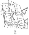
- Figure 4 is a perspective view of two amenity pockets of Figure 1 in deployed and stowed positions, respectively.
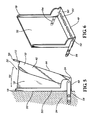
- Figure 5 is a side view of an amenity pocket of according to an alternative embodiment of the present invention.
- Figure 6 is a perspective view of a mounting structure that is coupled to the amenity pocket of Figure 5 .
- Figure 7 is a perspective view of an amenity pocket of according to another alternative embodiment of the present invention.
- Embodiments of the invention provide amenity pockets for use with a vehicle seat. While the amenity pockets are discussed for use with aircraft seats, they are by no means so limited. Rather, embodiments of the amenity pockets may be used in vehicle seats of any type. Similarly, the amenity pockets may be mounted to vehicle walls, bulkheads, or otherwise as appropriate or desired.
- FIGS 1-4 illustrate one embodiment of an amenity pocket 10.
- the amenity pocket 10 comprises a rigid structure 12, a deployment mechanism 16, and a hinge 54.
- a latch 20 may be used to retain the amenity pocket 10 in a stowed position.
- the rigid structure 12 provides the shape of the amenity pocket 10.
- the rigid structure 12 comprises two sides 22, a base 24, and a back 26.
- the base 24 includes a plurality of apertures 28. These apertures 28 may provide ventilation into the amenity pocket 10, as well as providing clean-out holes so that undesirable trash and debris does not become lodged in the bottom of the amenity pocket 10.
- the back 26 may also include a plurality of apertures 27. These apertures 27 may provide ventilation into the amenity pocket 10, as well as providing visual inspection holes for passengers to confirm that no personal items remain in the amenity pocket 10 when preparing to disembark from the vehicle.
- the rigid structure 12 may have any shape that encloses an area 30 formed between the amenity pocket 10 and a surface 32 to which the amenity pocket 10 is mounted.
- the surface 32 is a surface within a vehicle.
- the surface 32 is a rear surface of a passenger seat 34.
- the surface 32 may be a back surface of a mounting structure 18.
- the rigid structure 12 may be positioned between the surface 32 and a tray table (not shown). In other embodiments, as shown in Figure 4 , the rigid structure 12 may be positioned on the surface 32 in a location where a tray table is typically mounted. The rigid structure 12 may also be positioned on the surface 32 below an area 35. In some embodiments, the area 35 may include a video display or other equipment for passenger input or viewing.
- the depth of the area 30 is determined generally by the length of each side 22 of the rigid structure 12.
- the sides 22, base 24, and back 26 may have any suitable shape including rectilinear, curved, angled, or other similar shape.
- the rigid structure 12 may be formed of materials including but not limited to aluminum, sheet metal, stainless steel, other metallic material, composite material, injection molded or thermoformed plastic, or other similar material that provides sufficient strength to withstand a desired load.
- an interior surface 36 of the rigid structure 12 is coupled to a filler 38.
- the filler 38 may be formed of materials including but not limited to viscoelastic materials, foam materials, or other similar materials.
- the filler 38 and the interior surface 36 may be coupled in any suitable manner including but not limited to glue, mechanical fasteners, or other appropriate chemical or mechanical means.
- the filler 38 creates a resilient surface to lessen the impact force created when objects stored with the amenity pocket 10 come into contact with the rigid structure 12.
- the filler 38 may be coupled to a protective surface 40.
- the protective surface 40 may be formed of materials including but not limited to leather, vinyl, felt, cloth, plastic, woven fabrics, non-woven fabrics, synthetic fabrics, or other similar materials.
- the protective surface 40 and the filler 38 may be coupled in any suitable manner including but not limited to glue, mechanical fasteners, or other appropriate chemical or mechanical means.
- the protective surface 40 is designed to provide additional protection for items stored within the amenity pocket 10.
- a cover 42 may be coupled to an outer surface 44 of the rigid structure 12.
- the cover 42 may be formed of materials including but not limited to leather, vinyl, felt, cloth, plastic, woven fabrics, non-woven fabrics, synthetic fabrics, or other similar materials.
- the cover 42 and the outer surface 44 may be coupled in any suitable manner including but not limited to glue, mechanical fasteners, or other appropriate chemical or mechanical means.
- the rigid structure 12 is pivotally coupled directly to the surface 32.
- the hinge 54 is coupled to an aperture 46 positioned near the base of each side 22.
- the hinge 54 may be located in the center along the base 24 of the rigid structure 12 or any other suitable attachment location that allows the rigid structure 12 to pivot relative to the surface 32.
- each side 22 of the rigid structure 12 is coupled directly to the surface 32 via the deployment mechanism 16.
- the deployment mechanism 16 may include but is not limited to gussets, wherein the gussets may be formed of materials including but not limited to leather, cloth, plastic, woven fabrics, non-woven fabrics, and synthetic fabrics.
- the rigid structure 12 is pivotally coupled to the mounting structure 18, wherein the mounting structure 18 comprises a back portion that forms the surface 32, and the mounting structure 18 is in turn coupled to the passenger seat 34 or other vehicle surface.
- the mounting structure 18 includes a base 48 and two sides 50.
- the mounting structure 18 may be formed of materials including but not limited to sheet metal, stainless steel, other metallic material, composite material, or other similar material that provides sufficient strength to withstand a desired load.
- the base 48 of the mounting structure 18 is positioned below the base 24 of the rigid structure 12.
- the base 48 of the mounting structure 18 may have any suitable shape including rectilinear, curved, angled, or other similar shape.
- the base 48 may also include a plurality of apertures 52 that align with the plurality of apertures 28 of the base 24 of the rigid structure 12. These apertures 52 also provide ventilation into the amenity pocket 10, as well as providing clean-out holes to so that undesirable trash and debris does not become lodged in the bottom of the amenity pocket 10.
- At least a portion of the sides 50 of the mounting structure 18 may have substantially the same width as the sides 22 of the mounting structure 18.
- the sides 50 of the mounting structure 18 may taper inward away from the base 48 to a narrower width.
- each side 50 of the mounting structure 18 has a constant width along its length.
- Each side 50 of the mounting structure 18 is coupled to each side 22 of the mounting structure 18 via the deployment mechanism 16.
- the side 50 of the mounting structure 18 and the side 22 of the rigid structure 12 are pivotally coupled to one another near the bases 48 and 24.
- the hinge 54 is located on the sides of the mounting structure 18. In other embodiments, the hinge 54 may be located in the center of the mounting structure 18 or any other suitable attachment location that allows the rigid structure 12 to pivot relative to the mounting structure 18.
- the rigid structure 12 may pivot relative to the surface 32 so that the back 26 creates an angle of varying size relative to the surface 32.
- the maximum angle of travel by rigid structure 12, also referred as a deployment angle 56 may include a range of 10 degrees to 90 degrees. In other embodiments, the deployment angle is limited to 15 degrees.
- the deployment angle 56 is provided by the deployment mechanism 16. In other embodiments, the deployment angle 56 may be limited by other means. Moreover, the deployment angle 56 may be adjusted to accommodate a variety of stops. In these embodiments, a ratcheting device or ball-detent device may be combined with the deployment mechanism 16 to allow the rigid structure 12 to be positioned at a variety of deployment angles 56. For example, the deployment angle 56 may be incremented to allow the amenity pocket 10 to also function as a table. In this embodiment, the deployment angle 56 substantially aligns the back 26 with a horizontal plane.
- the amenity pocket 10 is stowed by coupling the rigid structure 12 to the surface 32 in a manner that prevents the rigid structure 12 from pivoting relative to the surface 32.
- the rigid structure 12 includes a projection 58 that engages with the latch 20.
- the latch 20 is mounted to the surface 32.
- the type of engagement between the latch 20 and the projection 58 include but are not limited to the type of latch commonly used for mounted tray tables on an aircraft, a slam latch, a pivot latch, snaps, hook and loop fasteners, snap-fit, or any other suitable releasable fastening device.
Landscapes
- Engineering & Computer Science (AREA)
- Aviation & Aerospace Engineering (AREA)
- Vehicle Step Arrangements And Article Storage (AREA)
- Seats For Vehicles (AREA)
- Chair Legs, Seat Parts, And Backrests (AREA)
Claims (14)
- Tasche mit Komfortmerkmal, umfassend:a) eine formstabile Struktur (12), die eine Rückseite (26), einen Boden (24) und zwei Seiten (22) umfasst;b) eine Fahrzeugfläche (32), wobei der Boden der formstabilen Struktur mit der Fahrzeugfläche drehgelenkig verbunden ist;
undc) einen Entfaltungsmechanismus (16), wobei der Entfaltungsmechanismus einen Entfaltungswinkel der formstabilen Struktur relativ zu der Fahrzeugfläche von ungleich Null bewirkt, wenn die formstabile Struktur entfaltet wird;
dadurch gekennzeichnet, dass:d) der Entfaltungsmechanismus (16) zumindest zwei Winkelstücke aufweist, wobei jedes Winkelstück mit der Fahrzeugfläche (32) verbunden ist und mit einer Seite (22) der formstabilen Struktur (12) verbunden ist. - Tasche mit Komfortmerkmal nach Anspruch 1, wobei der Entfaltungswinkel mindestens 15 Grad beträgt.
- Tasche mit Komfortmerkmal nach Anspruch 1 oder 2, wobei der Entfaltungsmechanismus (16) durch eine Reihe von gestuften Anschlägen mehrere Entfaltungswinkel vorsieht.
- Tasche mit Komfortmerkmal nach Anspruch 1 bis 3, wobei der Entfaltungswinkel im Wesentlichen die Rückseite der formstabilen Struktur nach einer waagerechten Ebene ausrichtet.
- Tasche mit Komfortmerkmal nach einem der Ansprüche 1 bis 4, des Weiteren umfassend eine Rastklinke (20) zur lösbaren Verbindung der formstabilen Struktur (12) mit der Fahrzeugfläche (32).
- Tasche mit Komfortmerkmal nach einem der Ansprüche 1 bis 5, des Weiteren umfassend ein Futterstück (38), das mit einer Innenfläche der formstabilen Struktur (12) verbunden ist.
- Tasche mit Komfortmerkmal nach Anspruch 6, wobei das Futterstück (38) aus einer Gruppe ausgewählt ist, die aus Styropor, viskoelastischen Werkstoffen oder hoch verdichtetem Schaum besteht.
- Tasche mit Komfortmerkmal nach Anspruch 6 oder 7, des Weiteren umfassend eine Schutz gewährende Fläche (40), die mit dem Futterstück (38) verbunden ist.
- Tasche mit Komfortmerkmal nach einem der Ansprüche 1 bis 8, des Weiteren umfassend eine Abdeckung (42), die mit einer Außenfläche der formstabilen Struktur (12) verbunden ist.
- Tasche mit Komfortmerkmal nach einem der Ansprüche 1 bis 9, des Weiteren umfassend eine Befestigungsstruktur (18), wobei die Befestigungsstruktur einen Boden (48) aufweist, der mit dem Boden (24) der formstabilen Struktur (12) drehgelenkig verbunden ist, und bei der die Befestigungsstruktur mit der Fahrzeugfläche (32) verbunden ist.
- Tasche mit Komfortmerkmal nach einem der Ansprüche 1 bis 10, wobei die Fahrzeugfläche (32) eine Fahrgastsitzlehne ist.
- Verfahren zum Entfalten einer Tasche (10) mit Komfortmerkmal nach einem der Ansprüche 1 bis 11, in Verbindung mit Anspruch 5 gelesen, die Schritte umfassend:a) Lösen der Rastklinke (20) zur Freigabe der formstabilen Struktur (12) von der Fahrzeugfläche (32),
undb) Drehen der formstabilen Struktur in den Entfaltungswinkel. - Sitz für ein Personenfahrzeug, der eine Rückseite und eine Tasche (10) mit Komfortmerkmal nach einem der Ansprüche 1 bis 11 aufweist.
- Luftfahrzeug mit einer Vielzahl von Sitzen (34) nach Anspruch 13.
Priority Applications (1)
| Application Number | Priority Date | Filing Date | Title |
|---|---|---|---|
| EP13153932.2A EP2589536B1 (de) | 2009-03-30 | 2010-03-30 | Komfort-Tasche |
Applications Claiming Priority (2)
| Application Number | Priority Date | Filing Date | Title |
|---|---|---|---|
| US16454109P | 2009-03-30 | 2009-03-30 | |
| PCT/US2010/029150 WO2010117759A1 (en) | 2009-03-30 | 2010-03-30 | Amenity pocket |
Related Child Applications (2)
| Application Number | Title | Priority Date | Filing Date |
|---|---|---|---|
| EP13153932.2A Division EP2589536B1 (de) | 2009-03-30 | 2010-03-30 | Komfort-Tasche |
| EP13153932.2 Division-Into | 2013-02-04 |
Publications (2)
| Publication Number | Publication Date |
|---|---|
| EP2414232A1 EP2414232A1 (de) | 2012-02-08 |
| EP2414232B1 true EP2414232B1 (de) | 2013-05-01 |
Family
ID=42668634
Family Applications (2)
| Application Number | Title | Priority Date | Filing Date |
|---|---|---|---|
| EP10712839.9A Not-in-force EP2414232B1 (de) | 2009-03-30 | 2010-03-30 | Komforttasche |
| EP13153932.2A Not-in-force EP2589536B1 (de) | 2009-03-30 | 2010-03-30 | Komfort-Tasche |
Family Applications After (1)
| Application Number | Title | Priority Date | Filing Date |
|---|---|---|---|
| EP13153932.2A Not-in-force EP2589536B1 (de) | 2009-03-30 | 2010-03-30 | Komfort-Tasche |
Country Status (4)
| Country | Link |
|---|---|
| US (1) | US8152234B2 (de) |
| EP (2) | EP2414232B1 (de) |
| CA (1) | CA2756980A1 (de) |
| WO (1) | WO2010117759A1 (de) |
Families Citing this family (18)
| Publication number | Priority date | Publication date | Assignee | Title |
|---|---|---|---|---|
| GB201107061D0 (en) * | 2011-04-27 | 2011-06-08 | Bentley Motors Ltd | Vehicle seat and trim |
| US8544928B2 (en) * | 2012-01-04 | 2013-10-01 | Ford Global Technologies, Llc | Flexible storage compartment for vehicle interior trim |
| DE102013100877A1 (de) * | 2013-01-29 | 2014-07-31 | Recaro Aircraft Seating Gmbh & Co. Kg | Flugzeugsitzrückenlehne |
| US20150136921A1 (en) * | 2013-11-15 | 2015-05-21 | Bertolini Corporation | Accessory holder for stackable chair |
| GB2526776A (en) * | 2014-04-07 | 2015-12-09 | Design Que Ltd | A retainer for retaining at least one article against a support surface |
| US9517727B2 (en) * | 2014-05-15 | 2016-12-13 | GM Global Technology Operations LLC | Pocket forming trim panel for a vehicle door and method |
| NZ729740A (en) * | 2014-09-25 | 2020-08-28 | King Furniture Australia Pty Ltd | “an article of furniture” |
| US9573528B1 (en) * | 2015-08-25 | 2017-02-21 | Ford Global Technologies, Llc | Integrated seatback storage |
| DE202016106446U1 (de) * | 2016-11-17 | 2017-01-27 | Lear Corporation | Kartenfachanordnung |
| US10377315B2 (en) * | 2017-01-16 | 2019-08-13 | Ford Global Technologies, Llc | In-board seat storage |
| GB2572159A (en) * | 2018-03-20 | 2019-09-25 | Mirus Aircraft Seating Ltd | Storage pocket |
| US11365754B2 (en) * | 2019-04-18 | 2022-06-21 | Ami Industries, Inc. | Detachable fastener assembly |
| US11225328B1 (en) | 2020-07-10 | 2022-01-18 | B/E Aerospace, Inc. | System including pocket |
| KR102990792B1 (ko) | 2020-09-29 | 2026-07-13 | 현대자동차주식회사 | 시트백 포켓 |
| US11325709B1 (en) | 2020-12-23 | 2022-05-10 | B/E Aerospace, Inc. | Upper shell including an actuatable pocket for an aircraft seat |
| US11873102B2 (en) | 2022-04-11 | 2024-01-16 | B/E Aerospace, Inc. | Implementations of deployable seatback pockets |
| US12004663B2 (en) * | 2022-06-28 | 2024-06-11 | L2 Furniture, LLC | Chair apparatus |
| PL448354A1 (pl) * | 2024-04-18 | 2025-10-20 | Grygiel Joanna Cityspace | Zespół kieszeni fotela |
Family Cites Families (15)
| Publication number | Priority date | Publication date | Assignee | Title |
|---|---|---|---|---|
| US365326A (en) * | 1887-06-21 | Alfeed c | ||
| US333853A (en) * | 1886-01-05 | Eichaed p | ||
| US1276713A (en) * | 1918-03-06 | 1918-08-27 | Carlos M Biedma | School-bench. |
| US1646266A (en) * | 1922-08-26 | 1927-10-18 | Baker Raulang Co | Receptacle |
| US1527056A (en) * | 1924-03-17 | 1925-02-17 | Martin Mattie | Shopping bag or parcel holder |
| US2841211A (en) | 1957-12-02 | 1958-07-01 | Thompson Mfg Company | Chair attachment |
| DE1961565A1 (de) * | 1969-12-09 | 1971-06-16 | Walter Schneider | Vordersitz fuer Personenkraftwagen |
| JPS60110544A (ja) | 1983-10-24 | 1985-06-17 | Tachikawa Spring Co Ltd | 車両用シ−トのポケツト |
| FR2613299B1 (fr) * | 1987-04-03 | 1990-08-24 | Peugeot | Agencement d'un vide-poches dans un vehicule automobile |
| US5292174A (en) * | 1991-10-22 | 1994-03-08 | Tachi-S Co., Ltd. | Pocket structure in automotive seat |
| JPH0648252A (ja) * | 1992-07-31 | 1994-02-22 | Kenji Shirai | 座席の傘立て取付構造 |
| US5695240A (en) * | 1996-05-13 | 1997-12-09 | Fuselage Engineering Services | Chair construction and passenger aircraft compartment including same |
| DE102004016255B8 (de) * | 2004-04-02 | 2005-12-15 | Itw Automotive Products Gmbh & Co. Kg | Kopfstütze für die Vordersitze von Automobilen |
| US7371341B2 (en) * | 2004-05-10 | 2008-05-13 | International Automotive Components Group North America, Inc. | Method of forming a vehicle component |
| DE102004050082B4 (de) * | 2004-10-14 | 2010-01-07 | Airbus Deutschland Gmbh | Passagiersitz mit Gepäckfach |
-
2010
- 2010-03-30 EP EP10712839.9A patent/EP2414232B1/de not_active Not-in-force
- 2010-03-30 CA CA2756980A patent/CA2756980A1/en not_active Abandoned
- 2010-03-30 EP EP13153932.2A patent/EP2589536B1/de not_active Not-in-force
- 2010-03-30 US US12/750,112 patent/US8152234B2/en active Active
- 2010-03-30 WO PCT/US2010/029150 patent/WO2010117759A1/en not_active Ceased
Also Published As
| Publication number | Publication date |
|---|---|
| WO2010117759A1 (en) | 2010-10-14 |
| EP2589536B1 (de) | 2014-07-02 |
| CA2756980A1 (en) | 2010-10-14 |
| US20100244506A1 (en) | 2010-09-30 |
| US8152234B2 (en) | 2012-04-10 |
| EP2414232A1 (de) | 2012-02-08 |
| EP2589536A1 (de) | 2013-05-08 |
Similar Documents
| Publication | Publication Date | Title |
|---|---|---|
| EP2589536B1 (de) | Komfort-Tasche | |
| EP2528473B1 (de) | Sitzlehnenanordnung | |
| US6276582B1 (en) | Item restraint device for vehicle seats | |
| US8801073B1 (en) | Luggage retention system | |
| US9340143B2 (en) | Adjustable cargo track system on side panel | |
| US20120139303A1 (en) | Display assembly | |
| US20160297533A1 (en) | Aircraft seating assembly | |
| WO1993024028A1 (en) | Carrying case for laptop computer | |
| US20150321614A1 (en) | Internal map pocket | |
| US10843603B2 (en) | Composite seating components | |
| US20060061121A1 (en) | Independent divan door and drawer assembly | |
| CN105480156B (zh) | 隔板总成及包括该隔板总成的车辆 | |
| EP3543128A1 (de) | Stautasche | |
| US9931989B2 (en) | Light weight low cost stretching load cover | |
| US8894140B2 (en) | Vehicle accessory for transporting objects | |
| US9079513B2 (en) | Luggage retention system | |
| EP4419384A1 (de) | Vorrichtung für den laderaum eines fahrzeugs | |
| EP3708429A1 (de) | Fahrzeug mit fahrzeugsitz, sitzschublade, sitzrahmen und bewegungseinheit | |
| US20050218172A1 (en) | Entertainment device storage case adapted for interconnection to a vehicle seat | |
| US20230127076A1 (en) | Portable tray for use with a console in a vehicle | |
| US20230115357A1 (en) | Foldable Vehicle Seat | |
| JP5316859B2 (ja) | 車内の床下収納構造 | |
| US20260116541A1 (en) | Locking device for a tray and an additional support | |
| EP4299443B1 (de) | System beinhaltend eine stautasche | |
| US12472858B2 (en) | Multi-purpose interior cabin lid for vehicle |
Legal Events
| Date | Code | Title | Description |
|---|---|---|---|
| PUAI | Public reference made under article 153(3) epc to a published international application that has entered the european phase |
Free format text: ORIGINAL CODE: 0009012 |
|
| 17P | Request for examination filed |
Effective date: 20111017 |
|
| AK | Designated contracting states |
Kind code of ref document: A1 Designated state(s): AT BE BG CH CY CZ DE DK EE ES FI FR GB GR HR HU IE IS IT LI LT LU LV MC MK MT NL NO PL PT RO SE SI SK SM TR |
|
| DAX | Request for extension of the european patent (deleted) | ||
| GRAP | Despatch of communication of intention to grant a patent |
Free format text: ORIGINAL CODE: EPIDOSNIGR1 |
|
| GRAS | Grant fee paid |
Free format text: ORIGINAL CODE: EPIDOSNIGR3 |
|
| GRAP | Despatch of communication of intention to grant a patent |
Free format text: ORIGINAL CODE: EPIDOSNIGR1 |
|
| GRAA | (expected) grant |
Free format text: ORIGINAL CODE: 0009210 |
|
| AK | Designated contracting states |
Kind code of ref document: B1 Designated state(s): AT BE BG CH CY CZ DE DK EE ES FI FR GB GR HR HU IE IS IT LI LT LU LV MC MK MT NL NO PL PT RO SE SI SK SM TR |
|
| REG | Reference to a national code |
Ref country code: GB Ref legal event code: FG4D |
|
| REG | Reference to a national code |
Ref country code: AT Ref legal event code: REF Ref document number: 609766 Country of ref document: AT Kind code of ref document: T Effective date: 20130515 Ref country code: CH Ref legal event code: EP |
|
| REG | Reference to a national code |
Ref country code: IE Ref legal event code: FG4D |
|
| RAP2 | Party data changed (patent owner data changed or rights of a patent transferred) |
Owner name: ZODIAC SEATS US LLC |
|
| REG | Reference to a national code |
Ref country code: DE Ref legal event code: R096 Ref document number: 602010006707 Country of ref document: DE Effective date: 20130627 |
|
| REG | Reference to a national code |
Ref country code: AT Ref legal event code: MK05 Ref document number: 609766 Country of ref document: AT Kind code of ref document: T Effective date: 20130501 |
|
| REG | Reference to a national code |
Ref country code: DE Ref legal event code: R081 Ref document number: 602010006707 Country of ref document: DE Owner name: ZODIAC SEATS US LLC, GAINESVILLE, US Free format text: FORMER OWNER: WEBER AIRCRAFT LLC, GAINESVILLE, TEX., US Effective date: 20130805 Ref country code: DE Ref legal event code: R081 Ref document number: 602010006707 Country of ref document: DE Owner name: ZODIAC SEATS US LLC, US Free format text: FORMER OWNER: WEBER AIRCRAFT LLC, GAINESVILLE, US Effective date: 20130805 |
|
| REG | Reference to a national code |
Ref country code: NL Ref legal event code: VDEP Effective date: 20130501 |
|
| REG | Reference to a national code |
Ref country code: LT Ref legal event code: MG4D |
|
| PG25 | Lapsed in a contracting state [announced via postgrant information from national office to epo] |
Ref country code: IS Free format text: LAPSE BECAUSE OF FAILURE TO SUBMIT A TRANSLATION OF THE DESCRIPTION OR TO PAY THE FEE WITHIN THE PRESCRIBED TIME-LIMIT Effective date: 20130901 Ref country code: GR Free format text: LAPSE BECAUSE OF FAILURE TO SUBMIT A TRANSLATION OF THE DESCRIPTION OR TO PAY THE FEE WITHIN THE PRESCRIBED TIME-LIMIT Effective date: 20130802 Ref country code: FI Free format text: LAPSE BECAUSE OF FAILURE TO SUBMIT A TRANSLATION OF THE DESCRIPTION OR TO PAY THE FEE WITHIN THE PRESCRIBED TIME-LIMIT Effective date: 20130501 Ref country code: ES Free format text: LAPSE BECAUSE OF FAILURE TO SUBMIT A TRANSLATION OF THE DESCRIPTION OR TO PAY THE FEE WITHIN THE PRESCRIBED TIME-LIMIT Effective date: 20130812 Ref country code: AT Free format text: LAPSE BECAUSE OF FAILURE TO SUBMIT A TRANSLATION OF THE DESCRIPTION OR TO PAY THE FEE WITHIN THE PRESCRIBED TIME-LIMIT Effective date: 20130501 Ref country code: SI Free format text: LAPSE BECAUSE OF FAILURE TO SUBMIT A TRANSLATION OF THE DESCRIPTION OR TO PAY THE FEE WITHIN THE PRESCRIBED TIME-LIMIT Effective date: 20130501 Ref country code: SE Free format text: LAPSE BECAUSE OF FAILURE TO SUBMIT A TRANSLATION OF THE DESCRIPTION OR TO PAY THE FEE WITHIN THE PRESCRIBED TIME-LIMIT Effective date: 20130501 Ref country code: NO Free format text: LAPSE BECAUSE OF FAILURE TO SUBMIT A TRANSLATION OF THE DESCRIPTION OR TO PAY THE FEE WITHIN THE PRESCRIBED TIME-LIMIT Effective date: 20130801 Ref country code: LT Free format text: LAPSE BECAUSE OF FAILURE TO SUBMIT A TRANSLATION OF THE DESCRIPTION OR TO PAY THE FEE WITHIN THE PRESCRIBED TIME-LIMIT Effective date: 20130501 Ref country code: PT Free format text: LAPSE BECAUSE OF FAILURE TO SUBMIT A TRANSLATION OF THE DESCRIPTION OR TO PAY THE FEE WITHIN THE PRESCRIBED TIME-LIMIT Effective date: 20130902 |
|
| PG25 | Lapsed in a contracting state [announced via postgrant information from national office to epo] |
Ref country code: CY Free format text: LAPSE BECAUSE OF FAILURE TO SUBMIT A TRANSLATION OF THE DESCRIPTION OR TO PAY THE FEE WITHIN THE PRESCRIBED TIME-LIMIT Effective date: 20130501 Ref country code: PL Free format text: LAPSE BECAUSE OF FAILURE TO SUBMIT A TRANSLATION OF THE DESCRIPTION OR TO PAY THE FEE WITHIN THE PRESCRIBED TIME-LIMIT Effective date: 20130501 Ref country code: HR Free format text: LAPSE BECAUSE OF FAILURE TO SUBMIT A TRANSLATION OF THE DESCRIPTION OR TO PAY THE FEE WITHIN THE PRESCRIBED TIME-LIMIT Effective date: 20130501 Ref country code: BG Free format text: LAPSE BECAUSE OF FAILURE TO SUBMIT A TRANSLATION OF THE DESCRIPTION OR TO PAY THE FEE WITHIN THE PRESCRIBED TIME-LIMIT Effective date: 20130801 |
|
| PG25 | Lapsed in a contracting state [announced via postgrant information from national office to epo] |
Ref country code: LV Free format text: LAPSE BECAUSE OF FAILURE TO SUBMIT A TRANSLATION OF THE DESCRIPTION OR TO PAY THE FEE WITHIN THE PRESCRIBED TIME-LIMIT Effective date: 20130501 |
|
| PG25 | Lapsed in a contracting state [announced via postgrant information from national office to epo] |
Ref country code: BE Free format text: LAPSE BECAUSE OF FAILURE TO SUBMIT A TRANSLATION OF THE DESCRIPTION OR TO PAY THE FEE WITHIN THE PRESCRIBED TIME-LIMIT Effective date: 20130501 Ref country code: EE Free format text: LAPSE BECAUSE OF FAILURE TO SUBMIT A TRANSLATION OF THE DESCRIPTION OR TO PAY THE FEE WITHIN THE PRESCRIBED TIME-LIMIT Effective date: 20130501 Ref country code: SK Free format text: LAPSE BECAUSE OF FAILURE TO SUBMIT A TRANSLATION OF THE DESCRIPTION OR TO PAY THE FEE WITHIN THE PRESCRIBED TIME-LIMIT Effective date: 20130501 Ref country code: CZ Free format text: LAPSE BECAUSE OF FAILURE TO SUBMIT A TRANSLATION OF THE DESCRIPTION OR TO PAY THE FEE WITHIN THE PRESCRIBED TIME-LIMIT Effective date: 20130501 Ref country code: DK Free format text: LAPSE BECAUSE OF FAILURE TO SUBMIT A TRANSLATION OF THE DESCRIPTION OR TO PAY THE FEE WITHIN THE PRESCRIBED TIME-LIMIT Effective date: 20130501 |
|
| PG25 | Lapsed in a contracting state [announced via postgrant information from national office to epo] |
Ref country code: RO Free format text: LAPSE BECAUSE OF FAILURE TO SUBMIT A TRANSLATION OF THE DESCRIPTION OR TO PAY THE FEE WITHIN THE PRESCRIBED TIME-LIMIT Effective date: 20130501 Ref country code: NL Free format text: LAPSE BECAUSE OF FAILURE TO SUBMIT A TRANSLATION OF THE DESCRIPTION OR TO PAY THE FEE WITHIN THE PRESCRIBED TIME-LIMIT Effective date: 20130501 Ref country code: IT Free format text: LAPSE BECAUSE OF FAILURE TO SUBMIT A TRANSLATION OF THE DESCRIPTION OR TO PAY THE FEE WITHIN THE PRESCRIBED TIME-LIMIT Effective date: 20130501 |
|
| PLBE | No opposition filed within time limit |
Free format text: ORIGINAL CODE: 0009261 |
|
| STAA | Information on the status of an ep patent application or granted ep patent |
Free format text: STATUS: NO OPPOSITION FILED WITHIN TIME LIMIT |
|
| REG | Reference to a national code |
Ref country code: DE Ref legal event code: R082 Ref document number: 602010006707 Country of ref document: DE Representative=s name: GODEMEYER BLUM LENZE PATENTANWAELTE, PARTNERSC, DE Ref country code: DE Ref legal event code: R082 Ref document number: 602010006707 Country of ref document: DE Representative=s name: GODEMEYER BLUM LENZE PARTNERSCHAFT, PATENTANWA, DE |
|
| 26N | No opposition filed |
Effective date: 20140204 |
|
| REG | Reference to a national code |
Ref country code: DE Ref legal event code: R097 Ref document number: 602010006707 Country of ref document: DE Effective date: 20140204 |
|
| PGFP | Annual fee paid to national office [announced via postgrant information from national office to epo] |
Ref country code: FR Payment date: 20140311 Year of fee payment: 5 |
|
| PGFP | Annual fee paid to national office [announced via postgrant information from national office to epo] |
Ref country code: GB Payment date: 20140326 Year of fee payment: 5 Ref country code: DE Payment date: 20140417 Year of fee payment: 5 |
|
| PG25 | Lapsed in a contracting state [announced via postgrant information from national office to epo] |
Ref country code: LU Free format text: LAPSE BECAUSE OF FAILURE TO SUBMIT A TRANSLATION OF THE DESCRIPTION OR TO PAY THE FEE WITHIN THE PRESCRIBED TIME-LIMIT Effective date: 20140330 |
|
| REG | Reference to a national code |
Ref country code: CH Ref legal event code: PL |
|
| REG | Reference to a national code |
Ref country code: IE Ref legal event code: MM4A |
|
| PG25 | Lapsed in a contracting state [announced via postgrant information from national office to epo] |
Ref country code: IE Free format text: LAPSE BECAUSE OF NON-PAYMENT OF DUE FEES Effective date: 20140330 Ref country code: CH Free format text: LAPSE BECAUSE OF NON-PAYMENT OF DUE FEES Effective date: 20140331 Ref country code: LI Free format text: LAPSE BECAUSE OF NON-PAYMENT OF DUE FEES Effective date: 20140331 |
|
| REG | Reference to a national code |
Ref country code: DE Ref legal event code: R119 Ref document number: 602010006707 Country of ref document: DE |
|
| GBPC | Gb: european patent ceased through non-payment of renewal fee |
Effective date: 20150330 |
|
| REG | Reference to a national code |
Ref country code: FR Ref legal event code: ST Effective date: 20151130 |
|
| PG25 | Lapsed in a contracting state [announced via postgrant information from national office to epo] |
Ref country code: DE Free format text: LAPSE BECAUSE OF NON-PAYMENT OF DUE FEES Effective date: 20151001 Ref country code: GB Free format text: LAPSE BECAUSE OF NON-PAYMENT OF DUE FEES Effective date: 20150330 |
|
| PG25 | Lapsed in a contracting state [announced via postgrant information from national office to epo] |
Ref country code: FR Free format text: LAPSE BECAUSE OF NON-PAYMENT OF DUE FEES Effective date: 20150331 Ref country code: MT Free format text: LAPSE BECAUSE OF FAILURE TO SUBMIT A TRANSLATION OF THE DESCRIPTION OR TO PAY THE FEE WITHIN THE PRESCRIBED TIME-LIMIT Effective date: 20130501 |
|
| PG25 | Lapsed in a contracting state [announced via postgrant information from national office to epo] |
Ref country code: SM Free format text: LAPSE BECAUSE OF FAILURE TO SUBMIT A TRANSLATION OF THE DESCRIPTION OR TO PAY THE FEE WITHIN THE PRESCRIBED TIME-LIMIT Effective date: 20130501 |
|
| PG25 | Lapsed in a contracting state [announced via postgrant information from national office to epo] |
Ref country code: MC Free format text: LAPSE BECAUSE OF FAILURE TO SUBMIT A TRANSLATION OF THE DESCRIPTION OR TO PAY THE FEE WITHIN THE PRESCRIBED TIME-LIMIT Effective date: 20130501 |
|
| PG25 | Lapsed in a contracting state [announced via postgrant information from national office to epo] |
Ref country code: TR Free format text: LAPSE BECAUSE OF FAILURE TO SUBMIT A TRANSLATION OF THE DESCRIPTION OR TO PAY THE FEE WITHIN THE PRESCRIBED TIME-LIMIT Effective date: 20130501 Ref country code: HU Free format text: LAPSE BECAUSE OF FAILURE TO SUBMIT A TRANSLATION OF THE DESCRIPTION OR TO PAY THE FEE WITHIN THE PRESCRIBED TIME-LIMIT; INVALID AB INITIO Effective date: 20100330 |
|
| PG25 | Lapsed in a contracting state [announced via postgrant information from national office to epo] |
Ref country code: MK Free format text: LAPSE BECAUSE OF FAILURE TO SUBMIT A TRANSLATION OF THE DESCRIPTION OR TO PAY THE FEE WITHIN THE PRESCRIBED TIME-LIMIT Effective date: 20130501 |