EP2413680A1 - Vehicle-mounted electronic device - Google Patents
Vehicle-mounted electronic device Download PDFInfo
- Publication number
- EP2413680A1 EP2413680A1 EP10755612A EP10755612A EP2413680A1 EP 2413680 A1 EP2413680 A1 EP 2413680A1 EP 10755612 A EP10755612 A EP 10755612A EP 10755612 A EP10755612 A EP 10755612A EP 2413680 A1 EP2413680 A1 EP 2413680A1
- Authority
- EP
- European Patent Office
- Prior art keywords
- heat
- section
- generating electronic
- vehicle
- metallic
- Prior art date
- Legal status (The legal status is an assumption and is not a legal conclusion. Google has not performed a legal analysis and makes no representation as to the accuracy of the status listed.)
- Withdrawn
Links
Images




Classifications
-
- H—ELECTRICITY
- H05—ELECTRIC TECHNIQUES NOT OTHERWISE PROVIDED FOR
- H05K—PRINTED CIRCUITS; CASINGS OR CONSTRUCTIONAL DETAILS OF ELECTRIC APPARATUS; MANUFACTURE OF ASSEMBLAGES OF ELECTRICAL COMPONENTS
- H05K7/00—Constructional details common to different types of electric apparatus
- H05K7/20—Modifications to facilitate cooling, ventilating, or heating
- H05K7/20845—Modifications to facilitate cooling, ventilating, or heating for automotive electronic casings
- H05K7/20854—Heat transfer by conduction from internal heat source to heat radiating structure
Definitions
- the present invention relates to a vehicle-mounted electronic apparatus such as a control unit that accommodates a circuit substrate in a resin case.
- a vehicle-mounted electronic apparatus has: a case, in which part of a bottom surface or side surface has an opening; a connector that sticks out from the opening of the case and that can be connected to an external device that inputs and outputs an electrical signal and an external power supply that supplies power; a circuit substrate that is provided inside the case, and that, by electrically connecting with the connector, performs signal processing using the electrical signal received as input from the external device and the power supplied from the external power supply; a metallic wiring board that comprises a plurality of metallic wires, and that is provided on an inner section on the bottom surface of the case and electrically connects with the circuit substrate; and a heat-generating electronic component that has its bottom surface connected on part of metallic wires in the metallic wiring board, and, in this vehicle-mounted electronic apparatus, the thickness of a metallic wire in the metallic wiring board that connects with the bottom surface of the heat-generating electronic component is thicker than the thickness of the connector terminal.
- the vehicle-mounted electronic apparatus of the present invention even when the method of inputting and outputting electrical signals to and from connectors changes, it is possible to release heat from heat-generating electronic components efficiently, without redesigning component of the vehicle-mounted electronic apparatus such as the case and metallic wiring board, or adding additional processing steps. That is to say, according to the present invention, it is possible to provide a vehicle-mounted electronic apparatus that makes components multifunctional while maintaining heat-releasing characteristics.
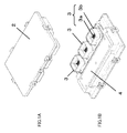
- FIG.IA is a perspective view showing a vehicle-mounted electronic apparatus according to the present invention from above.
- FIG.1B is a perspective view showing a vehicle-mounted electronic apparatus according to the present invention from below.
- FIG.2 is an exploded perspective view of a vehicle-mounted electronic apparatus according to the present invention from above;
- a vehicle-mounted electronic apparatus has case 2, connectors 3, heat-sink plate 4, circuit substrate 5, heat-generating electronic components 6, and metallic wiring board 7.
- Case 2 is comprised of upper case 2a and lower case 2b, and is a structure to cover circuit substrate 5 in a state upper case 2a and lower case 2b are coupled. Also, case 2 is made of resin or metal. Lower case 2b has opening section 2c. Upper case 2a has hook section 2d in each side. Lower case 2b has lock section 2e in each side. When these hook section 2d and lock section 2e are fitted together, upper case 2a and lower case 2b are fixed. With the present embodiment, opening section 2c is provided in the bottom surface of lower case 2b, but it is equally possible to provide opening section 2c on a side surface of lower case 2b. Also, case 2 may adopt a structure that does not provide hook section 2d and lock section 2e and that instead couples upper case 2a and lower case 2b by means of a screw, for example.
- Connectors 3 each have metallic terminals 3a and protecting section 3b that protects metallic terminal 3a.
- Metallic terminals 3a include an input terminal for receiving as input an electrical signal from an external electronic apparatus; an output terminal for outputting an electrical signal to an external electronic apparatus; a power supply terminal for connecting with a power supply and acquiring power; and a ground terminal to connect with the ground. As shown in FIG.1B and FIG.2 , connectors 3 stick out from opening section 2c of lower case 2b.
- heat-sink plate 4 is connected to the outer bottom surface of lower case 2b.
- This heat-sink plate 4 is made of metal having a high heat-releasing effect, and is, for example, an aluminum plate or copper plate.
- Circuit substrate 5 has a signal electronic component (not shown) that performs signal processing and that has a low calorific value.
- This circuit substrate 5 is made of, for example, glass epoxy.
- connectors 3 and metallic terminals 3a are electrically connected by alloy-junctioning or press-fitting metallic terminals 3a in a through hole provided in one end section on the bottom surface of circuit substrate 5. Then, circuit substrate 5 receives as input an electrical signal from an external device via metallic terminal 3a of an input terminal, is supplied power from an external power supply via metallic terminal 3a of a power supply terminal, and outputs an electrical signal to an external device via metallic terminal 3a of an output terminal.
- circuit substrate 5 and connector 3 are electrically connected via a through hole according to the present embodiment, any method of connection is possible.
- circuit substrate 5 and connector 3 may be connected by wire bonding and suchlike means, without using a through hole.
- FIG.3 is an enlarged perspective view of lower case 2b in FIG.2 .
- Heat-generating electronic components 6 and metallic wiring board 7 are provided in lower case 2b.
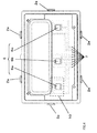
- FIG.4 illustrates metallic wiring board 7 provided inside lower case 2b, showing lower case 2b shown in FIG.3 from above.
- Heat-generating electronic components 6 are comprised of power-related electronic components of a high calorific value, such as transistors. As shown in FIG.2 to FIG.4 , heat-generating electronic components 6 provided in lower case 2b are comprised of three heat-generating electronic components 6a, 6b and 6c. Heat-sink plate 4 is provided on the back surface of lower case 2b in which heat-generating electronic components 6 are provided.
- FIG.5 is an enlarged view illustrating metallic wiring board 7 in part 10 enclosed by a dotted line in FIG.4 .
- electronic component 6a is removed from part 10 enclosed by a dotted line in FIG.4 , to explain metallic wiring board 7.
- FIG.6 is a perspective view for explaining an area around heat-generating electronic component 6a, showing FIG.3 from above.
- lower case 2b is removed in order to explain the positional relationships between heat-generating electronic components 6a and metallic wiring board 7.
- FIG.7 is an A-A cross-sectional view of FIG.6 .
- FIG.7 will be described including lower case 2b.
- FIG.5 to FIG.7 explain the positional relationships and connection relationships between heat-generating electronic component 6a and metallic wiring board 7.
- heat-generating electronic component 6a has two lead terminals 8 wire-bonded with the inner circuitry of heat-generating component 6a.
- the positional relationships and connection relationships between heat-generating electronic component 6a and metallic wiring board 7 shown in FIG.5 to FIG.7 apply alike to heat-generating electronic components 6b and 6c. Consequently, the positional relationships or connection relationships between heat-generating electronic components 6b and 6c and metallic wiring boar 7 will not be illustrated by way of drawing or explained.
- Metallic wiring board 7 has a plurality of metallic wires. Each metallic wire is formed L-shaped (see FIG.3 ). As shown in FIG.2 and FIG.3 , end section 7a, which is one end of each metallic wire formed in an L shape, sticks out nearly vertically from the bottom surface of lower case 2b. This end section 7a is electrically connected with circuit substrate 5, by means of alloy-junctioning or press-fitting, in a through hole provide in the other end section on the bottom surface of circuit substrate 5.
- metallic wiring board 7 and circuit substrate 5 are electrically connected via a through hole according to the present embodiment, any method of connection is possible.
- metallic wiring board 7 and circuit substrate 5 may be connected by wire bonding and suchlike means without using a through hole.
- metallic wiring board 7 is insert-molded in lower case 2b except for end section 7a.
- Metallic wiring board 7 is formed with input section 7b, output section 7c and power supplying section 7d.
- Input section 7b provides metallic wiring for inputting a signal from circuit substrate 5 to heat-generating electronic component 6a.
- Output section 7c provides metallic wiring for outputting a signal from heat-generating electronic components 6 to circuit substrate 5.
- Power supplying section 7d provides metallic wiring for supplying power from circuit substrate 5 to heat-generating electronic component 6a.
- connecting section 7e electrically connects with lead terminal 8, so that input section 7b, output section 7c and heat-generating electronic components 6a are electrically connected.
- mounting section 7f In the front end section of power supplying section 7d, mounting section 7f, where heat-generating electronic component 6a is placed and installed, is provided.
- This mounting section 7f is part of the upper surface of power supplying section 7d exposing from lower case 2b, as shown in FIG.7 .
- power supplying section 7d and heat-generating electronic component 6a are electrically connected.
- mounting section 7f has a greater metal thickness than input section 7b and output section 7c.
- the proportion of the weight of metallic wiring board 7 in a vehicle-mounted electronic apparatus is 10 % or so, for example, and therefore the weight of metallic wiring board 7 cannot be ignored. Consequently, making the metal of power supplying section 7d including mounting section 7f thicker contradicts the demand for reducing the weight of a vehicle-mounted electronic apparatus.
- metallic wiring board 7 is formed an L shape, but may be formed in other shapes such as a U-shape as well.
- the thickness of the metallic wiring board depends upon the thickness of connector terminals and is usually the same thickness as the connector terminal.
- the thickness of each metallic wire in metallic wiring board 7 does not depend upon the thickness of connector terminals and can be set freely. Consequently, it is possible to improve the heat releasing effect by making the thickness of power supplying section 7d, which includes mounting section 7f where heat-generating electronic components 6 of high calorific values are mounted, thicker than metallic terminal 3a of connector 3.
- the thickness of metallic wiring in input section 7b and output section 7c connecting with circuit substrate 5 where signal electronic components of low calorific values are mounted can be made equal to or thinner than the thickness of metallic terminal 3a. Consequently, it is possible to improve the heat releasing effect without increasing the weight of a vehicle-mounted electronic apparatus, and reduce the weight of a vehicle-mounted electronic apparatus.
- an electrical signal that is received as input from an external electronic apparatus via an input terminal in metallic terminals 3a of connector 3 is subjected to signal processing using signal electronic component in circuit substrate 5.
- An electrical signal having been subjected to signal processing is inputted in end section 7a of input section 7b in metallic wiring board 7.
- An electrical signal that is inputted in input section 7b is subject to signal processing by power-supplied heat-generating electronic components 6.
- This supply of power is given from power supplying section 7d, via a power supply terminal in metallic terminals 3a.
- An electrical signal having been subjected to signal processing in heat-generating electronic components 6 is inputted in output section 7c in metallic wiring board 7.
- An electrical signal received as input in output section 7c is subjected to signal processing by signal electronic components in circuit substrate 5.
- An electrical signal having been subjected to signal processing is outputted to an external electronic apparatus via an output terminal in metallic terminals 3a of connectors 3.
- the vehicle-mounted electronic apparatus of the present embodiment has a structure in which the metal thickness of a metallic wire connecting with the bottom surface of heat-generating electronic components 6 in metallic wiring board 7 of lower case 2b is thicker than the thickness of other metallic wires. Consequently, with the vehicle-mounted electronic apparatus of the present embodiment, it is possible to release heat efficiently while reducing the weight.
- the vehicle-mounted electronic apparatus has a structure in which input and output signals to and from heat-generating electronic components 6 do not pass connectors 3 directly but instead are inputted to or outputted from connectors 3 via signal electronic components on circuit substrate 5. Consequently, with the vehicle-mounted electronic apparatus of the present embodiment, it is possible to continue using lower case 2b in which metallic wiring board 7 is insert-molded and make the components multifunctional even when the specifications of connector input-output arrangement varies between vehicle types.
- a vehicle-mounted electronic apparatus is provided with a heat-sink plate to improve the heat releasing effect of heat-generating electronic components 6, it is possible to release heat as long as metallic wiring board 7 of the present invention is provided, so that it is not mandatory to provide heat-sink plate 4.
- a metallic wire that connects with the bottom surface of heat-generating electronic components 6 is made power supplying section 7d and metallic wires that connect with heat-generating electronic components 6 via lead terminal 8 are made input section 7b and output section 7c, but this is by no means limiting.
- metallic wires connecting with heat-generating electronic components 6 via lead terminal 8 become an output section and power supplying section.
- metallic wires connecting with heat-generating electronic components 6 via lead terminal 8 become an input section and power supplying section. That is to say, heat-generating electronic component 6 is placed on the surface of one of an input section and an output section in metallic wiring board 7 and connects with the bottom surface.
- the thickness of a metallic wire connecting with the bottom surface of heat-generating electronic component 6 is thicker than the thickness of metallic terminal 3a of connectors 3.
- the thickness of a metallic wire connecting via lead terminal 8, not connecting with the bottom surface of heat-generating electronic component 6, is thinner than the thickness of metallic terminal 3a of connectors 3.
- metallic wiring board 7 to connect with one heat-generating electronic component 6 is three, this number may as well be greater than three. Also, this number of terminals may be less than three, and needs to be at least two or greater. In the event there are two terminals, metallic wiring board 7 has only an input section and an output section.
- the vehicle-mounted electronic apparatus according to the present invention is suitable for use as a vehicle-mounted electronic apparatus having varying specifications per vehicle type.
Landscapes
- Physics & Mathematics (AREA)
- Thermal Sciences (AREA)
- Engineering & Computer Science (AREA)
- Microelectronics & Electronic Packaging (AREA)
- Cooling Or The Like Of Electrical Apparatus (AREA)
- Structure Of Printed Boards (AREA)
Abstract
Description
- The present invention relates to a vehicle-mounted electronic apparatus such as a control unit that accommodates a circuit substrate in a resin case.
- With a conventional vehicle-mounted electronic apparatus, in order to miniaturize and lower the cost of a control unit, a heating block and others are made unnecessary by connecting heat-generating electronic components to a metallic wiring board (see, for example, patent literature 1). Also, with a general vehicle-mounted electronic apparatus, in order to release the heat produced by heat-generating electronic components, a heat-sink plate is insert-molded in the bottom surface of a case, and heat-generating electronic components are placed on this heat-sink plate (see, for example, patent literature 2).
-
- PTL 1
Japanese Patent Application Laid-Open No.1999-284370 -
PTL 2
Japanese Patent Application Laid-Open No.2006-179763 - However, with the molding method disclosed in patent literature 1, there is a problem of difficulty components multifunctional. This is because, with the molding method disclosed in patent literature I, the connector-signal arrangement is fixed by insert-molding connectors and a case as one, so that, when the method of inputting and outputting electrical signals to and from connectors changes, all components of a vehicle-mounted electronic apparatus, such as a case, heat-generating electronic components and metallic wiring board need to be redesigned. By contrast with this, if a molding method is used that does not insert-mold an mounting section of heat-generating electronic components in a case and that instead places heat-generating electronic components on a circuit substrate, a vehicle-mounted electronic apparatus suffers performance deterioration due to the heat produced by heat-generating electronic components. Also, with the molding method disclosed by
patent literature 2, a step of insert-molding a heat-sink plate in the bottom surface of a case to release heat is necessary, and, although the heat produced by heat-generating electronic components can be released, there is a problem of poor productivity. - In view of the above problems, it is an object of the present invention to provide a vehicle-mounted electronic apparatus that, even when the method of inputting and outputting electrical signals to and from connectors changes, makes it possible to release heat from heat-generating electronic components efficiently and makes the components of the vehicle-mounted electronic apparatus multifunctional, without redesigning various components.
- In order to achieve the above object, a vehicle-mounted electronic apparatus according to the present invention has: a case, in which part of a bottom surface or side surface has an opening; a connector that sticks out from the opening of the case and that can be connected to an external device that inputs and outputs an electrical signal and an external power supply that supplies power; a circuit substrate that is provided inside the case, and that, by electrically connecting with the connector, performs signal processing using the electrical signal received as input from the external device and the power supplied from the external power supply; a metallic wiring board that comprises a plurality of metallic wires, and that is provided on an inner section on the bottom surface of the case and electrically connects with the circuit substrate; and a heat-generating electronic component that has its bottom surface connected on part of metallic wires in the metallic wiring board, and, in this vehicle-mounted electronic apparatus, the thickness of a metallic wire in the metallic wiring board that connects with the bottom surface of the heat-generating electronic component is thicker than the thickness of the connector terminal.
- With the vehicle-mounted electronic apparatus of the present invention, even when the method of inputting and outputting electrical signals to and from connectors changes, it is possible to release heat from heat-generating electronic components efficiently, without redesigning component of the vehicle-mounted electronic apparatus such as the case and metallic wiring board, or adding additional processing steps. That is to say, according to the present invention, it is possible to provide a vehicle-mounted electronic apparatus that makes components multifunctional while maintaining heat-releasing characteristics.
-
- FIG. is a perspective view of a vehicle-mounted electronic apparatus according to an embodiment of the present invention;
-
FIG.2 is a perspective view of a vehicle-mounted electronic apparatus according the embodiment; -
FIG.3 is an enlarged view of a lower case, which is a principle part of a vehicle-mounted electronic apparatus according to the embodiment; -
FIG.4 illustrates a metallic wiring board provided inside a lower case according to the embodiment; -
FIG.5 illustrates a metallic wiring board according to the embodiment; -
FIG.6 is a perspective view illustrating an area around heat-generating electronic components according to the embodiment; and -
FIG.7 is a cross-sectional view illustrating an area around heat-generating electronic components according to the embodiment. - An embodiment of a vehicle-mounted electronic apparatus of the present invention will be described now with reference to the accompanying drawings.
- FIG.IA is a perspective view showing a vehicle-mounted electronic apparatus according to the present invention from above.
FIG.1B is a perspective view showing a vehicle-mounted electronic apparatus according to the present invention from below. -
FIG.2 is an exploded perspective view of a vehicle-mounted electronic apparatus according to the present invention from above; - As shown in
FIG.1 andFIG.2 , a vehicle-mounted electronic apparatus hascase 2,connectors 3, heat-sink plate 4, circuit substrate 5, heat-generatingelectronic components 6, andmetallic wiring board 7. -
Case 2 is comprised ofupper case 2a andlower case 2b, and is a structure to cover circuit substrate 5 in a stateupper case 2a andlower case 2b are coupled. Also,case 2 is made of resin or metal.Lower case 2b has openingsection 2c.Upper case 2a hashook section 2d in each side.Lower case 2b haslock section 2e in each side. When thesehook section 2d andlock section 2e are fitted together,upper case 2a andlower case 2b are fixed. With the present embodiment, openingsection 2c is provided in the bottom surface oflower case 2b, but it is equally possible to provideopening section 2c on a side surface oflower case 2b. Also,case 2 may adopt a structure that does not providehook section 2d andlock section 2e and that instead couplesupper case 2a andlower case 2b by means of a screw, for example. -
Connectors 3 each havemetallic terminals 3a and protectingsection 3b that protectsmetallic terminal 3a.Metallic terminals 3a include an input terminal for receiving as input an electrical signal from an external electronic apparatus; an output terminal for outputting an electrical signal to an external electronic apparatus; a power supply terminal for connecting with a power supply and acquiring power; and a ground terminal to connect with the ground. As shown inFIG.1B andFIG.2 ,connectors 3 stick out fromopening section 2c oflower case 2b. - As shown in
FIG.1B , heat-sink plate 4 is connected to the outer bottom surface oflower case 2b. This heat-sink plate 4 is made of metal having a high heat-releasing effect, and is, for example, an aluminum plate or copper plate. - Circuit substrate 5 has a signal electronic component (not shown) that performs signal processing and that has a low calorific value. This circuit substrate 5 is made of, for example, glass epoxy. Also, in this circuit substrate 5,
connectors 3 andmetallic terminals 3a are electrically connected by alloy-junctioning or press-fittingmetallic terminals 3a in a through hole provided in one end section on the bottom surface of circuit substrate 5. Then, circuit substrate 5 receives as input an electrical signal from an external device viametallic terminal 3a of an input terminal, is supplied power from an external power supply viametallic terminal 3a of a power supply terminal, and outputs an electrical signal to an external device viametallic terminal 3a of an output terminal. - Although circuit substrate 5 and
connector 3 are electrically connected via a through hole according to the present embodiment, any method of connection is possible. For example, circuit substrate 5 andconnector 3 may be connected by wire bonding and suchlike means, without using a through hole. - The inner structure of
lower case 2b will be described next. -
FIG.3 is an enlarged perspective view oflower case 2b inFIG.2 . Heat-generatingelectronic components 6 andmetallic wiring board 7 are provided inlower case 2b. -
FIG.4 illustratesmetallic wiring board 7 provided insidelower case 2b, showinglower case 2b shown inFIG.3 from above. - Heat-generating
electronic components 6 are comprised of power-related electronic components of a high calorific value, such as transistors. As shown inFIG.2 to FIG.4 , heat-generatingelectronic components 6 provided inlower case 2b are comprised of three heat-generatingelectronic components sink plate 4 is provided on the back surface oflower case 2b in which heat-generatingelectronic components 6 are provided. -
FIG.5 is an enlarged view illustratingmetallic wiring board 7 inpart 10 enclosed by a dotted line inFIG.4 . InFIG.5 ,electronic component 6a is removed frompart 10 enclosed by a dotted line inFIG.4 , to explainmetallic wiring board 7. -
FIG.6 is a perspective view for explaining an area around heat-generatingelectronic component 6a, showingFIG.3 from above. InFIG.6 ,lower case 2b is removed in order to explain the positional relationships between heat-generatingelectronic components 6a andmetallic wiring board 7. -
FIG.7 is an A-A cross-sectional view ofFIG.6 .FIG.7 will be described includinglower case 2b. -
FIG.5 to FIG.7 explain the positional relationships and connection relationships between heat-generatingelectronic component 6a andmetallic wiring board 7. As shown inFIG.6 , heat-generatingelectronic component 6a has twolead terminals 8 wire-bonded with the inner circuitry of heat-generatingcomponent 6a. The positional relationships and connection relationships between heat-generatingelectronic component 6a andmetallic wiring board 7 shown inFIG.5 to FIG.7 , apply alike to heat-generatingelectronic components electronic components metallic wiring boar 7 will not be illustrated by way of drawing or explained. -
Metallic wiring board 7 has a plurality of metallic wires. Each metallic wire is formed L-shaped (seeFIG.3 ). As shown inFIG.2 andFIG.3 ,end section 7a, which is one end of each metallic wire formed in an L shape, sticks out nearly vertically from the bottom surface oflower case 2b. Thisend section 7a is electrically connected with circuit substrate 5, by means of alloy-junctioning or press-fitting, in a through hole provide in the other end section on the bottom surface of circuit substrate 5. - Incidentally, although
metallic wiring board 7 and circuit substrate 5 are electrically connected via a through hole according to the present embodiment, any method of connection is possible. For example,metallic wiring board 7 and circuit substrate 5 may be connected by wire bonding and suchlike means without using a through hole. - Also, as shown in
FIG.3 andFIG.4 ,metallic wiring board 7 is insert-molded inlower case 2b except forend section 7a. -
Metallic wiring board 7 is formed withinput section 7b,output section 7c andpower supplying section 7d.Input section 7b provides metallic wiring for inputting a signal from circuit substrate 5 to heat-generatingelectronic component 6a.Output section 7c provides metallic wiring for outputting a signal from heat-generatingelectronic components 6 to circuit substrate 5.Power supplying section 7d provides metallic wiring for supplying power from circuit substrate 5 to heat-generatingelectronic component 6a. - As shown in
FIG.5 to FIG.7 , in the front end section ofinput section 7b and the front end section of output section 7cin other words, in end sections on the side ofmetallic wiring board 7 apart fromend section 7a -- connectingsection 7e that exposes fromlower case 2b and electrically connects with heat-generatingelectronic components 6a is provided. This connectingsection 7e electrically connects withlead terminal 8, so thatinput section 7b,output section 7c and heat-generatingelectronic components 6a are electrically connected. - In the front end section of
power supplying section 7d, mountingsection 7f, where heat-generatingelectronic component 6a is placed and installed, is provided. This mountingsection 7f is part of the upper surface ofpower supplying section 7d exposing fromlower case 2b, as shown inFIG.7 . When the bottom surface of heat-generatingelectronic component 6a is placed upon the upper surface of this mountingsection 7f,power supplying section 7d and heat-generatingelectronic component 6a are electrically connected. - As shown in
FIG.7 , mountingsection 7f has a greater metal thickness thaninput section 7b andoutput section 7c. The proportion of the weight ofmetallic wiring board 7 in a vehicle-mounted electronic apparatus is 10 % or so, for example, and therefore the weight ofmetallic wiring board 7 cannot be ignored. Consequently, making the metal ofpower supplying section 7d including mountingsection 7f thicker contradicts the demand for reducing the weight of a vehicle-mounted electronic apparatus. - With the present embodiment, the metal of
power supplying section 7d including to which power of a high calorific value is supplied from a power supply, is made thick, and the metal ofinput section 7b andoutput section 7c, to which electrical signals of a low calorific value is inputted from circuit substrate 5, is made thinner. By this means, it is possible to improve the heat-releasing effect while maintaining the weight ofmetallic wiring board 7. Consequently, with the present embodiment, it is possible to both improve heat-release performance and reduce the weight of a vehicle-mounted electronic apparatus. With the present embodiment,metallic wiring board 7 is formed an L shape, but may be formed in other shapes such as a U-shape as well. - Heretofore, when a metallic wiring board is provided inside a case forming a connector and a case as one, the thickness of the metallic wiring board depends upon the thickness of connector terminals and is usually the same thickness as the connector terminal. However, with the present embodiment, upon providing mounting
section 7f, the thickness of each metallic wire inmetallic wiring board 7 does not depend upon the thickness of connector terminals and can be set freely. Consequently, it is possible to improve the heat releasing effect by making the thickness ofpower supplying section 7d, which includes mountingsection 7f where heat-generatingelectronic components 6 of high calorific values are mounted, thicker than metallic terminal 3a ofconnector 3. - On the other hand, the thickness of metallic wiring in
input section 7b andoutput section 7c connecting with circuit substrate 5 where signal electronic components of low calorific values are mounted, can be made equal to or thinner than the thickness ofmetallic terminal 3a. Consequently, it is possible to improve the heat releasing effect without increasing the weight of a vehicle-mounted electronic apparatus, and reduce the weight of a vehicle-mounted electronic apparatus. - In particular, generally one hundred or more vehicle-mounted electronic apparatuses are mounted in a vehicle to control the vehicle electrically, weight reduction is possible on the order of kilograms per vehicle, so that significant improvement of mileage is possible. Also, the step if insert-molding a heat-sink plate inside a case cab be omitted, so that it is possible to improve the prevision of processing and reduce the time of processing to improve productivity.
- With this structure of a vehicle-mounted electronic apparatus, an electrical signal that is received as input from an external electronic apparatus via an input terminal in
metallic terminals 3a ofconnector 3 is subjected to signal processing using signal electronic component in circuit substrate 5. An electrical signal having been subjected to signal processing is inputted inend section 7a ofinput section 7b inmetallic wiring board 7. An electrical signal that is inputted ininput section 7b is subject to signal processing by power-supplied heat-generatingelectronic components 6. This supply of power is given frompower supplying section 7d, via a power supply terminal inmetallic terminals 3a. An electrical signal having been subjected to signal processing in heat-generatingelectronic components 6 is inputted inoutput section 7c inmetallic wiring board 7. An electrical signal received as input inoutput section 7c is subjected to signal processing by signal electronic components in circuit substrate 5. An electrical signal having been subjected to signal processing is outputted to an external electronic apparatus via an output terminal inmetallic terminals 3a ofconnectors 3. - The vehicle-mounted electronic apparatus of the present embodiment has a structure in which the metal thickness of a metallic wire connecting with the bottom surface of heat-generating
electronic components 6 inmetallic wiring board 7 oflower case 2b is thicker than the thickness of other metallic wires. Consequently, with the vehicle-mounted electronic apparatus of the present embodiment, it is possible to release heat efficiently while reducing the weight. - Furthermore, the vehicle-mounted electronic apparatus according to the present embodiment has a structure in which input and output signals to and from heat-generating
electronic components 6 do not passconnectors 3 directly but instead are inputted to or outputted fromconnectors 3 via signal electronic components on circuit substrate 5. Consequently, with the vehicle-mounted electronic apparatus of the present embodiment, it is possible to continue usinglower case 2b in whichmetallic wiring board 7 is insert-molded and make the components multifunctional even when the specifications of connector input-output arrangement varies between vehicle types. - Although a vehicle-mounted electronic apparatus according to the present invention is provided with a heat-sink plate to improve the heat releasing effect of heat-generating
electronic components 6, it is possible to release heat as long asmetallic wiring board 7 of the present invention is provided, so that it is not mandatory to provide heat-sink plate 4. By this means, it is possible to reduce the weight of a vehicle-mounted electronic apparatus. Also, it is possible to reduce the labor of processing while maintaining the heat releasing effect bymetallic wiring board 7, and therefore it is possible to improve the productivity of a vehicle-mounted electronic apparatus. - Also, with the present embodiment, amongst a plurality of f metallic wires provided in
metallic wiring board 7, a metallic wire that connects with the bottom surface of heat-generatingelectronic components 6 is madepower supplying section 7d and metallic wires that connect with heat-generatingelectronic components 6 vialead terminal 8 are madeinput section 7b andoutput section 7c, but this is by no means limiting. - For example, it is possible to make a metallic wire that connects with the bottom surface of heat-generating
electronic components 6 an input section. In this case, metallic wires connecting with heat-generatingelectronic components 6 vialead terminal 8 become an output section and power supplying section. Also, it is equally possible to make a metallic wire connecting with the bottom surface of heat-generatingelectronic component 6 an output section. In this case, metallic wires connecting with heat-generatingelectronic components 6 vialead terminal 8 become an input section and power supplying section. That is to say, heat-generatingelectronic component 6 is placed on the surface of one of an input section and an output section inmetallic wiring board 7 and connects with the bottom surface. Then, inmetallic wiring board 7, the thickness of a metallic wire connecting with the bottom surface of heat-generatingelectronic component 6 is thicker than the thickness of metallic terminal 3a ofconnectors 3. On the other hand, inmetallic wiring board 7, the thickness of a metallic wire connecting vialead terminal 8, not connecting with the bottom surface of heat-generatingelectronic component 6, is thinner than the thickness of metallic terminal 3a ofconnectors 3. - Also, although the number of metallic wire terminals in
metallic wiring board 7 to connect with one heat-generatingelectronic component 6 is three, this number may as well be greater than three. Also, this number of terminals may be less than three, and needs to be at least two or greater. In the event there are two terminals,metallic wiring board 7 has only an input section and an output section. - The disclosure of Japanese Patent Application No.
2009-75557, filed on March 26, 2009 - The vehicle-mounted electronic apparatus according to the present invention is suitable for use as a vehicle-mounted electronic apparatus having varying specifications per vehicle type.
-
- 2
- Case
- 2a
- Upper case
- 2b
- Lower case
- 2b
- Lower case
- 3a
- Metallic terminal
- 3b
- Protecting section
- 4
- Heat-sink plate
- 5
- Circuit substrate
- 6
- Heat-generating electronic component
- 7
- Metallic wiring board
- 7a
- End section
- 7b
- Input section
- 7c
- Output section
- 7d
- Power supplying section
- 7e
- Connecting section
- 7f
- Mounting section
Claims (3)
- A vehicle-mounted electronic apparatus comprising:a case, in which part of a bottom surface or side surface has an opening;a connector that sticks out from the opening of the case and that can be connected to an external device that inputs and outputs an electrical signal and an external power supply that supplies power;a circuit substrate that is provided inside the case, and that, by electrically connecting with the connector, performs signal processing using the electrical signal received as input from the external device and the power supplied from the external power supply;a metallic wiring board that comprises a plurality of metallic wires, and that is provided on an inner section on the bottom surface of the case and electrically connects with the circuit substrate; anda heat-generating electronic component that has its bottom surface connected on part of metallic wires in the metallic wiring board, wherein a thickness of a metallic wire in the metallic wiring board that connects with the bottom surface of the heat-generating electronic component is thicker than a thickness of the connector terminal.
- The vehicle-mounted electronic apparatus according to claim 1, wherein the metallic wiring board comprises:an input section that inputs a signal from the circuit substrate to the heat-generating electronic component;an output section that outputs a signal from the heat-generating electronic component to the circuit substrate; anda power supplying section that supplies power to the heat-generating electronic component,wherein the bottom surface of the heat-generating electronic component connects with an upper surface of one of the input section, the output section and the power supplying section.
- The vehicle-mounted electronic apparatus according to claim 2, wherein:an electrical signal that is received as input from the connector is inputted in the input section via the circuit substrate;an electrical signal that is received as input in the input section is outputted to the output section via the heat-generating electronic component; andan electrical signal outputted to the output section is outputted to the connector via the circuit substrate.
Applications Claiming Priority (2)
| Application Number | Priority Date | Filing Date | Title |
|---|---|---|---|
| JP2009075557 | 2009-03-26 | ||
| PCT/JP2010/001845 WO2010109808A1 (en) | 2009-03-26 | 2010-03-15 | Vehicle-mounted electronic device |
Publications (2)
| Publication Number | Publication Date |
|---|---|
| EP2413680A1 true EP2413680A1 (en) | 2012-02-01 |
| EP2413680A4 EP2413680A4 (en) | 2013-05-29 |
Family
ID=42780508
Family Applications (1)
| Application Number | Title | Priority Date | Filing Date |
|---|---|---|---|
| EP10755612.8A Withdrawn EP2413680A4 (en) | 2009-03-26 | 2010-03-15 | ELECTRONIC DEVICE ON BOARD VEHICLE |
Country Status (5)
| Country | Link |
|---|---|
| US (1) | US8441800B2 (en) |
| EP (1) | EP2413680A4 (en) |
| JP (1) | JP5284462B2 (en) |
| CN (1) | CN102124828B (en) |
| WO (1) | WO2010109808A1 (en) |
Families Citing this family (9)
| Publication number | Priority date | Publication date | Assignee | Title |
|---|---|---|---|---|
| JP6073637B2 (en) * | 2012-10-18 | 2017-02-01 | 株式会社小糸製作所 | Electronic unit |
| US9099800B2 (en) * | 2012-11-09 | 2015-08-04 | Nsk Ltd. | Connector |
| US10890565B2 (en) * | 2017-06-22 | 2021-01-12 | Olympus America Inc. | Portable phased array test instrument |
| US11029985B2 (en) | 2018-01-19 | 2021-06-08 | Ge Aviation Systems Llc | Processor virtualization in unmanned vehicles |
| US10942509B2 (en) | 2018-01-19 | 2021-03-09 | Ge Aviation Systems Llc | Heterogeneous processing in unmanned vehicles |
| US11032919B2 (en) * | 2018-01-19 | 2021-06-08 | Ge Aviation Systems Llc | Control boxes and system-on-module circuit boards for unmanned vehicles |
| JP7222288B2 (en) * | 2019-03-28 | 2023-02-15 | 株式会社アイシン | Control device |
| TWI722836B (en) * | 2020-03-17 | 2021-03-21 | 群光電能科技股份有限公司 | Housing of power supply |
| JP2022079037A (en) * | 2020-11-16 | 2022-05-26 | 三菱電機株式会社 | In-vehicle electrical device |
Family Cites Families (37)
| Publication number | Priority date | Publication date | Assignee | Title |
|---|---|---|---|---|
| JPH066534B2 (en) | 1986-10-09 | 1994-01-26 | 積水化学工業株式会社 | Transdermal patch |
| JPS6393714U (en) * | 1986-12-10 | 1988-06-17 | ||
| US5023752A (en) * | 1989-10-31 | 1991-06-11 | General Motors Corporation | Electrical power distribution center |
| JP3261971B2 (en) | 1996-04-08 | 2002-03-04 | 住友電装株式会社 | Electrical junction box |
| JPH11284370A (en) | 1998-03-31 | 1999-10-15 | Matsushita Electric Ind Co Ltd | Connection structure of electric circuit |
| JP3785276B2 (en) * | 1998-09-10 | 2006-06-14 | 矢崎総業株式会社 | Electrical junction box |
| JP2001196770A (en) * | 2000-01-12 | 2001-07-19 | Omron Corp | control unit |
| JP3543713B2 (en) * | 2000-01-20 | 2004-07-21 | 住友電装株式会社 | Electrical junction box |
| JP2001211529A (en) * | 2000-01-20 | 2001-08-03 | Auto Network Gijutsu Kenkyusho:Kk | Electrical junction box |
| JP2001237557A (en) * | 2000-02-24 | 2001-08-31 | Keihin Corp | Electronic circuit board storage case |
| US6466447B2 (en) * | 2000-02-24 | 2002-10-15 | Denso Corporation | Electronic control unit having flexible wires connecting connector to circuit board |
| JP2002026251A (en) * | 2000-07-11 | 2002-01-25 | Toshiba Corp | Semiconductor device |
| DE10120715A1 (en) * | 2001-04-27 | 2002-11-28 | Bosch Gmbh Robert | Housing for an electrical device |
| JP2002359329A (en) * | 2001-05-30 | 2002-12-13 | Hitachi Ltd | Semiconductor device |
| JP2003348731A (en) * | 2002-05-22 | 2003-12-05 | Yazaki Corp | Bus bar wiring board and bus bar wiring board assembling method |
| CA2394403C (en) * | 2002-07-22 | 2012-01-10 | Celestica International Inc. | Component substrate for a printed circuit board and method of assemblying the substrate and the circuit board |
| JP4076459B2 (en) * | 2003-03-12 | 2008-04-16 | 株式会社オートネットワーク技術研究所 | BUSBAR COMPOSITION BOARD AND CIRCUIT COMPOSITION MANUFACTURING METHOD USING THE SAME |
| WO2004108450A1 (en) * | 2003-04-25 | 2004-12-16 | Ngk Spark Plug Co. Ltd | Air heater unit for motor vehicle and air heater system for motor vehicle |
| JP4211580B2 (en) * | 2003-11-18 | 2009-01-21 | 株式会社デンソー | Electronic device housing structure |
| DE102005016830A1 (en) * | 2004-04-14 | 2005-11-03 | Denso Corp., Kariya | Semiconductor device and method for its production |
| EP1759929A4 (en) * | 2004-05-31 | 2010-04-21 | Furukawa Electric Co Ltd | Power supply system for vehicle |
| US7548411B2 (en) * | 2004-10-29 | 2009-06-16 | Hitachi, Ltd. | Electronic circuit structure, power supply apparatus, power supply system, and electronic apparatus |
| JP4470688B2 (en) * | 2004-10-29 | 2010-06-02 | 株式会社日立製作所 | Mounting structure of bus bar structure, power supply device, power supply system, electronic circuit board, electronic device |
| JP2006179763A (en) | 2004-12-24 | 2006-07-06 | Denso Corp | Electronic equipment |
| CN1804933A (en) * | 2005-01-14 | 2006-07-19 | 江西巴士在线传媒有限公司 | Onboard digital audio/video electronic device |
| US7745930B2 (en) * | 2005-04-25 | 2010-06-29 | International Rectifier Corporation | Semiconductor device packages with substrates for redistributing semiconductor device electrodes |
| JP4594198B2 (en) * | 2005-09-02 | 2010-12-08 | 株式会社オートネットワーク技術研究所 | Electrical junction box |
| US20070075419A1 (en) * | 2005-09-06 | 2007-04-05 | Denso Corporation | Semiconductor device having metallic lead and electronic device having lead frame |
| JP4867280B2 (en) * | 2005-10-18 | 2012-02-01 | 株式会社ジェイテクト | Coating agent application method |
| JP4560477B2 (en) * | 2005-11-15 | 2010-10-13 | 日立オートモティブシステムズ株式会社 | Electronic control unit and waterproof case |
| JP4957048B2 (en) * | 2006-03-31 | 2012-06-20 | 株式会社ジェイテクト | Electronic control device |
| JP5232367B2 (en) * | 2006-07-12 | 2013-07-10 | ルネサスエレクトロニクス株式会社 | Semiconductor device |
| JP4923841B2 (en) | 2006-08-11 | 2012-04-25 | 住友電装株式会社 | Circuit material accommodated in electrical junction box and in-vehicle electrical junction box accommodating the circuit material |
| US7732351B2 (en) * | 2006-09-21 | 2010-06-08 | Semiconductor Energy Laboratory Co., Ltd. | Manufacturing method of semiconductor device and laser processing apparatus |
| US7982331B2 (en) * | 2006-12-29 | 2011-07-19 | Cummins Power Generation Ip, Inc. | Transfer switch assembly |
| JP2009075557A (en) | 2007-06-26 | 2009-04-09 | Carl Zeiss Smt Ag | Method and device for controlling a plurality of actuators and illumination devices for lithography |
| JP5116427B2 (en) * | 2007-10-11 | 2013-01-09 | 矢崎総業株式会社 | Electrical junction box |
-
2010
- 2010-03-15 EP EP10755612.8A patent/EP2413680A4/en not_active Withdrawn
- 2010-03-15 CN CN201080002287.1A patent/CN102124828B/en active Active
- 2010-03-15 WO PCT/JP2010/001845 patent/WO2010109808A1/en not_active Ceased
- 2010-03-15 JP JP2011505852A patent/JP5284462B2/en not_active Expired - Fee Related
- 2010-03-15 US US13/059,708 patent/US8441800B2/en not_active Expired - Fee Related
Also Published As
| Publication number | Publication date |
|---|---|
| WO2010109808A1 (en) | 2010-09-30 |
| CN102124828B (en) | 2014-11-12 |
| JPWO2010109808A1 (en) | 2012-09-27 |
| CN102124828A (en) | 2011-07-13 |
| EP2413680A4 (en) | 2013-05-29 |
| JP5284462B2 (en) | 2013-09-11 |
| US20110141706A1 (en) | 2011-06-16 |
| US8441800B2 (en) | 2013-05-14 |
Similar Documents
| Publication | Publication Date | Title |
|---|---|---|
| US8441800B2 (en) | Vehicle-mounted electronic device | |
| US5610799A (en) | Power module device | |
| CN104348041B (en) | Electronic device module | |
| EP3487272B1 (en) | Electronic control unit | |
| EP2685564B1 (en) | Electronics module and method for providing an electronics module | |
| CN114243331A (en) | Socket with interface | |
| CN101142721B (en) | Electrical Equipment | |
| CN101388597A (en) | Filter device and power conversion device connected with the filter device | |
| US6683789B1 (en) | Electronic control module for a removable connector and methods of assembling same | |
| US11011996B2 (en) | Power converter | |
| CN100438720C (en) | Integrated electrical module architecture for vehicles | |
| JP2000156924A (en) | Electrical connection box | |
| US20230253278A1 (en) | Semiconductor module with integrated current sensor | |
| US10653020B2 (en) | Electronic module and method for producing an electronic module | |
| US10944332B2 (en) | Power converter with shield plate and resin support member | |
| JP6104763B2 (en) | Power converter | |
| CN111463592B (en) | Electrical Equipment | |
| US20050078917A1 (en) | Optical active connector | |
| JP2017022184A (en) | Electronic component unit substrate, and electronic component unit | |
| JP2011165348A (en) | Connection structure of wire harness and printed circuit board | |
| CN112448212B (en) | Electronic equipment unit | |
| US11025022B2 (en) | Adapter for changing connector pitch and method for manufacturing same | |
| JP2017216419A (en) | Electronic device and method for manufacturing electronic device | |
| JP2007036760A (en) | Mounting structure of in-vehicle tuner module | |
| JPH07154947A (en) | Power semiconductor device |
Legal Events
| Date | Code | Title | Description |
|---|---|---|---|
| PUAI | Public reference made under article 153(3) epc to a published international application that has entered the european phase |
Free format text: ORIGINAL CODE: 0009012 |
|
| 17P | Request for examination filed |
Effective date: 20110302 |
|
| AK | Designated contracting states |
Kind code of ref document: A1 Designated state(s): AT BE BG CH CY CZ DE DK EE ES FI FR GB GR HR HU IE IS IT LI LT LU LV MC MK MT NL NO PL PT RO SE SI SK SM TR |
|
| DAX | Request for extension of the european patent (deleted) | ||
| A4 | Supplementary search report drawn up and despatched |
Effective date: 20130502 |
|
| RIC1 | Information provided on ipc code assigned before grant |
Ipc: H05K 7/20 20060101AFI20130424BHEP |
|
| RAP1 | Party data changed (applicant data changed or rights of an application transferred) |
Owner name: PANASONIC INTELLECTUAL PROPERTY MANAGEMENT CO., LT |
|
| RAP1 | Party data changed (applicant data changed or rights of an application transferred) |
Owner name: PANASONIC INTELLECTUAL PROPERTY MANAGEMENT CO., LT |
|
| 17Q | First examination report despatched |
Effective date: 20160919 |
|
| STAA | Information on the status of an ep patent application or granted ep patent |
Free format text: STATUS: EXAMINATION IS IN PROGRESS |
|
| STAA | Information on the status of an ep patent application or granted ep patent |
Free format text: STATUS: THE APPLICATION IS DEEMED TO BE WITHDRAWN |
|
| 18D | Application deemed to be withdrawn |
Effective date: 20190514 |