EP2413479A1 - Bus ring, and fixing structure thereof - Google Patents
Bus ring, and fixing structure thereof Download PDFInfo
- Publication number
- EP2413479A1 EP2413479A1 EP10755882A EP10755882A EP2413479A1 EP 2413479 A1 EP2413479 A1 EP 2413479A1 EP 10755882 A EP10755882 A EP 10755882A EP 10755882 A EP10755882 A EP 10755882A EP 2413479 A1 EP2413479 A1 EP 2413479A1
- Authority
- EP
- European Patent Office
- Prior art keywords
- stator
- bent portions
- bus ring
- conductive wires
- axial direction
- Prior art date
- Legal status (The legal status is an assumption and is not a legal conclusion. Google has not performed a legal analysis and makes no representation as to the accuracy of the status listed.)
- Withdrawn
Links
- 238000004804 winding Methods 0.000 claims abstract description 38
- 239000012212 insulator Substances 0.000 claims abstract description 21
- 238000009413 insulation Methods 0.000 description 5
- XEEYBQQBJWHFJM-UHFFFAOYSA-N Iron Chemical group [Fe] XEEYBQQBJWHFJM-UHFFFAOYSA-N 0.000 description 3
- 210000000078 claw Anatomy 0.000 description 2
- 230000003247 decreasing effect Effects 0.000 description 2
- 239000011347 resin Substances 0.000 description 2
- 229920005989 resin Polymers 0.000 description 2
- RYGMFSIKBFXOCR-UHFFFAOYSA-N Copper Chemical compound [Cu] RYGMFSIKBFXOCR-UHFFFAOYSA-N 0.000 description 1
- 230000004075 alteration Effects 0.000 description 1
- 230000000903 blocking effect Effects 0.000 description 1
- 239000004020 conductor Substances 0.000 description 1
- 229910052802 copper Inorganic materials 0.000 description 1
- 239000010949 copper Substances 0.000 description 1
- 230000000694 effects Effects 0.000 description 1
- 239000011810 insulating material Substances 0.000 description 1
- 239000000463 material Substances 0.000 description 1
- 230000004048 modification Effects 0.000 description 1
- 238000012986 modification Methods 0.000 description 1
- 238000003466 welding Methods 0.000 description 1
Images



Classifications
-
- H—ELECTRICITY
- H02—GENERATION; CONVERSION OR DISTRIBUTION OF ELECTRIC POWER
- H02K—DYNAMO-ELECTRIC MACHINES
- H02K3/00—Details of windings
- H02K3/04—Windings characterised by the conductor shape, form or construction, e.g. with bar conductors
- H02K3/18—Windings for salient poles
-
- H—ELECTRICITY
- H02—GENERATION; CONVERSION OR DISTRIBUTION OF ELECTRIC POWER
- H02K—DYNAMO-ELECTRIC MACHINES
- H02K3/00—Details of windings
- H02K3/46—Fastening of windings on the stator or rotor structure
- H02K3/52—Fastening salient pole windings or connections thereto
- H02K3/521—Fastening salient pole windings or connections thereto applicable to stators only
- H02K3/522—Fastening salient pole windings or connections thereto applicable to stators only for generally annular cores with salient poles
-
- H—ELECTRICITY
- H02—GENERATION; CONVERSION OR DISTRIBUTION OF ELECTRIC POWER
- H02K—DYNAMO-ELECTRIC MACHINES
- H02K3/00—Details of windings
- H02K3/46—Fastening of windings on the stator or rotor structure
-
- H—ELECTRICITY
- H02—GENERATION; CONVERSION OR DISTRIBUTION OF ELECTRIC POWER
- H02K—DYNAMO-ELECTRIC MACHINES
- H02K3/00—Details of windings
- H02K3/46—Fastening of windings on the stator or rotor structure
- H02K3/52—Fastening salient pole windings or connections thereto
-
- H—ELECTRICITY
- H02—GENERATION; CONVERSION OR DISTRIBUTION OF ELECTRIC POWER
- H02K—DYNAMO-ELECTRIC MACHINES
- H02K2203/00—Specific aspects not provided for in the other groups of this subclass relating to the windings
- H02K2203/09—Machines characterised by wiring elements other than wires, e.g. bus rings, for connecting the winding terminations
Definitions
- the present invention relates to a bus ring attached to a stator of a rotary electrical machine so as to connect a winding wound around a stator tooth and a fixing structure thereof.
- terminals in the shape of a staple are formed on a conductive wire curved in an arc shape.
- the terminals are in the shape of protruding in a radial direction of a ring-shaped stator and a winding wound around a stator tooth is connected to the terminals. It is, however, necessary to increase the outermost diameter of the bus ring for each protruding portion of the terminals, so that space that is greater than the thickness of a core back of a stator iron core is needed. As a result, it becomes necessary to increase the inner diameter of a housing for a rotary electrical machine. Accordingly, this causes a problem of hindering the downsizing of the rotary electrical machine.
- a bus ring attached to a stator having a plurality of stator teeth aligned in a circumferential direction and turning an end face thereof toward an axial direction of a rotary electrical machine along the end face, the bus ring is made by curving a conductive wire in an arc shape with a diameter smaller than that of the stator, wherein staple-shaped bent portions protruding in the axial direction are formed at the conductive wire and a winding wound around each of the plurality of stator teeth is connected to the bent portions.
- a plurality of conductive wires are respectively aligned in the axial direction.
- respective bent portions of the plurality of conductive wires are positioned in the circumferential direction.
- extending portions bent so as to respectively extend in a radial direction are formed at the plurality of conductive wires and the bent portions are formed at the conductive wires so as to be interposed between the extending portions.
- the bent portions respectively have a smaller width of the circumferential direction as the bent portions protrude in the axial direction.
- a fixing structure of the bus ring for attaching the bus ring to a stator having a plurality of stator teeth aligned in a circumferential direction and turning an end face of the stator toward an axial direction of a rotary electrical machine along the end face, wherein the bus ring is made by curving a conductive wire in an arc shape with a diameter smaller than that of the stator, in which staple-shaped bent portions protruding in the axial direction are formed at the conductive wires and a winding wound around each of the stator teeth is connected to the bent portions, and further, an insulator extending in the axial direction from the end face of the stator is interposed between each of the stator teeth and the winding to enter the insulator inside the conductive wire.
- the insulator supports the plurality of conductive wires at positions spaced away from the end face of the stator in the axial direction and respective bent portions of the plurality of conductive wires are different in length of protrusion of the bent portions in the axial direction.
- a bus ring which has no possibility of staple-shaped bent portion protruding in a radial direction of a stator iron core in a state where conductive wires are attached to a stator along an end face thereof because the bent portions protruding in an axial direction of a rotary electrical machine are formed at the conductive wires curved in an arc shape with a diameter smaller than that of the outer diameter of the stator iron core. Consequently, it is sufficient to use a minimum-size housing capable of housing the stator as a housing for a rotary electrical machine, which enables to downsize the rotary electrical machine.
- the bus ring of the present invention is capable of attaching fittings, typically, for screwing windings to the staple-shaped bent portions. Since it is possible to perform a task for connecting windings to such fittings outwards in the radial direction of the stator, the operator can smoothly connect the windings to the fittings because there is no interruption of the operator's hands caused by the stator. Further, it is possible to perform a task for connecting the windings to a plurality of bent portions formed at the conductive wire from a front face of each of the bent portions, so that it is possible for the operator to connect the windings to all of the bent portions in the same manner. This makes it easier to finish portions where the windings are connected to the bent portions in high grade.
- the rotary electrical machine has windings of at least two phases, there is no possibility of a plurality of conductive wires protruding in the radial direction of the stator by axially aligning the conductive wires.
- This makes it possible to downsize the rotary electrical machine regardless of the number of the conductive wires.
- there are advantages that it is possible to avoid the bent portions being overlapped and being an obstacle to other conductive wires when performing the aforementioned task in the bent portions of one conductive wire out of the plurality of conductive wires by aligning the plurality of conductive wires such that the respective bent portions of the plurality of conductive wires can be arranged in a circumferential direction.
- the conductive wires respectively have extending portions extending in the radial direction and bent portions interposed between the extending portions. This makes it possible to secure an insulation distance which will be described later. That is, in the case where a plurality of conductive wires are aligned in the axis direction, respective extending portions of these conductive wires radially extend. As a result, it is possible to keep an insulation distance which is essential to insulation between the bent portions of one conductive wire out of the plurality of conductive wires and other conductive wires even when approaching the conductive wires each other. This avoids the rotary electrical machine being unnecessarily long in the axial direction, resulting in downsizing of the rotary electrical machine.
- the bent portions may be in a shape of gradually reducing the width in the circumferential direction thereof as the bent portions axially protrude.
- each of the bent portions can be nipped in each of the fittings by allowing the fittings for connecting the windings to enter the bent portions and be pressed in the direction of projection of the bent portions. As a result, it is possible to easily perform positioning of the fittings with respect to the bent portions.
- the fixing structure of the bus ring of the present invention it is possible to support the plurality of conductive wires at positions spaced away from an end face of the stator in the axial direction.
- the housing of the rotary electrical machine with a minimum internal diameter that is capable of housing the stator may be used, resulting in downsizing of the entire rotary electrical machine.
- the respective bent portions of the plurality of conductive wires are different in length of protrusion of the bent portions in the axial direction. This makes it possible to set desirable space between the bent portions of respective conductive wires and the end face of the stator. For instance, it is possible to uniformly align the aforementioned space by long-protruding the bent portions thereof from the conductive wires in the axial direction as long as the plurality of conductive wires are relatively spaced away from the end face of the stator.
- FIG.1 shows a ring-shaped stator 3 turning an end face 1 thereof toward an axial direction of a rotary electrical machine pointed by an arrow S and a bus ring 5 attached to the stator 3 along the end face of the stator 3.
- a plurality of stator teeth 7 are aligned in a circumferential direction indicated by an arrow R.
- FIG. 2 shows the bus ring 5 removed from the stator 3.
- the aforementioned rotary electrical machine is not shown in figure due to obvious art, the rotary electrical machine may house the stator 3 inside the housing and rotate an output shaft together with a rotor.
- the bus ring 5 includes four conductive wires 9 curbed in the shape of an arc.
- each of the conductive wires 9 has a plurality of staple-shaped bent portions 11 protruding in an axial direction.
- the shape of an arc herein means a shape following a circle having a diameter of " ⁇ "
- the symbol " ⁇ " indicates the diameter of each of the conductive wires 9 and is set to be smaller than the diameter of an outer circumferential surface 13 of the stator 3 shown in FIG. 1 .
- the material for each of the conductive wires 9 is a conductor made of copper or the like and a surface of each of the conductive wires 9 may be covered with an insulating material.
- the cross section of each of the conductive wires 9 may be in the shape of a circle, an ellipse or a polygon.
- each of the conductive wires 9 may have extending portions 15 extending in a radial direction thereof and bent portions 11 respectively interposed between the extending portions 15.
- the diameter [ ⁇ max] of a circle circumscribing the outermost side of the radial direction of each of the conductive wires 9 is preferably smaller than the diameter of the outer circumferential surface 13 of the stator 3.
- the bent portions 11 are portions to which windings 17 would around the stator teeth 7 shown in FIG. 1 are connected, therefore, it is possible to attach fittings or the like for screwing ends of the windings 17.
- the width of the circumferential direction of a bent portion 11 is preferably reducing gradually as the bent portion 11 protrudes in the axial direction.
- the number of the conductive wires 9 shown in FIGs. 1 and 2 is set to be four because each of the windings 17 in the U-phase, V-phase, W-phase, and N-phase of the rotary electrical machine is connected to one conductive wire 9.
- the bus ring 5 may have one or more conductive wires 9 and the number of the conductive wires 9 may be increased or decreased according to the specifications of the rotary electrical machine.
- FIGs. 1 and 5 An insulator 25 is interposed between a stator tooth 7 and a winding 17. This point is applied to all stator teeth 7. Insulators 25 are respectively a bobbin made of a synthesized resin around which the windings 17 are wound and respectively have a support 27 protruding in the axial direction from the end face 1 of the stator 3. Alternatively, only supports 27 of the insulators 25 may be respectively made of a synthesized resin and the supports 27 and separated insulating paper may wrap the stator 3.
- Respective supports 27 of a plurality of insulators 25 shown in FIG. 1 are arranged in a cylindrical shape to enter inside the conductive wires 9. Since the conductive wires 9 are supported by the insulators 25 in this state, a holder or the like to attach the conductive wires 9 to the stator 3 is not needed. As a result, it is possible to reduce the number of parts for the rotary electrical machine. While the means for fixing the conductive wires 9 to the insulators 25 is not particularly limited, winding fittings 30 respectively having screw holes 31 and terminals 32 may be fixed to the supports 27 of the insulators 25. And then a screw is put through the hole 21 of the fitting 19 shown in FIG. 4 to be screwed up to the screw holes 31 of the winding fittings 30.
- the terminals 32 of the winding fittings 30 are portions to connect the ends of the windings 17.
- a numerical symbol 29 indicates a claw for positioning the conductive wires 9 in the supports 27 by engaging claws into the inside of the bent portions 11.
- each of the conductive wires 9 protruding in the radial direction of the stator 3 because it is possible to align the plurality of conductive wires 9 in the axial direction even though the number of the plurality of conductive wires 9 is increased or decreased. Consequently, the housing for a rotary electrical machine having a minimum inner diameter that enables the stator 3 to be housed may be sufficient, resulting in downsizing of the whole rotary electrical machine.
- the fixing structure 23 of the bus ring it is possible to avoid the bent portions 11 being overlapped to each other by aligning the positions of the respective bent portions 11 of the plurality of the conductive wires 9. Accordingly, when each of the windings 17 is connected to one bent portion 11 of one conductive wire out of the plurality of conductive wires 9, there is no possibility of the bent portions 11 of one conductive wire out of the plurality of the conductive wires 9 being blocked by the bent portions 11 of the other conductive wires 9.
- [d] denotes a length in which an extending portion 15 extends in a radial direction thereof and [s] denotes a length in which a bent portion 11 protrudes in an axial direction thereof.
- the plurality of conductive wires 9 supported by the insulators 25 respectively have the length [d] of the extending portion 15. Therefore, as shown in FIGs. 1 and 2 , an insulation distance essential to insulation is kept between the bent portions 11 of one conductive wire out of the plurality of conductive wires 9 and the other conductive wires 9.
- extending portions 15 may be omitted in the bus ring 5.
- the number of the bent portions 11 included in one conductive wire 9 is not limited.
- the present invention is applicable to rotary electrical machines.
Landscapes
- Engineering & Computer Science (AREA)
- Power Engineering (AREA)
- Insulation, Fastening Of Motor, Generator Windings (AREA)
- Windings For Motors And Generators (AREA)
Abstract
Description
- The present invention relates to a bus ring attached to a stator of a rotary electrical machine so as to connect a winding wound around a stator tooth and a fixing structure thereof.
- In a bus ring disclosed in Japanese Unexamined Patent Application Publication Nos.
JP 2004-096841 A JP 2006-067799 A - It is an object of the present invention to provide a bus ring and a fixing structure thereof to contribute downsizing of a rotary electrical machine.
- In a first preferred aspect, there is provided a bus ring according to the present invention attached to a stator having a plurality of stator teeth aligned in a circumferential direction and turning an end face thereof toward an axial direction of a rotary electrical machine along the end face, the bus ring is made by curving a conductive wire in an arc shape with a diameter smaller than that of the stator, wherein staple-shaped bent portions protruding in the axial direction are formed at the conductive wire and a winding wound around each of the plurality of stator teeth is connected to the bent portions.
- In a second preferred aspect of the bus ring according to the present invention, a plurality of conductive wires are respectively aligned in the axial direction.
- In a third preferred aspect of the bus ring according to the present invention, respective bent portions of the plurality of conductive wires are positioned in the circumferential direction.
- In a fourth preferred aspect of the bus ring according to the present invention, extending portions bent so as to respectively extend in a radial direction are formed at the plurality of conductive wires and the bent portions are formed at the conductive wires so as to be interposed between the extending portions.
- In a fifth preferred aspect of the bus ring according to the present invention, the bent portions respectively have a smaller width of the circumferential direction as the bent portions protrude in the axial direction.
- In a sixth preferred aspect of the present invention, there is provided a fixing structure of the bus ring according to the present invention for attaching the bus ring to a stator having a plurality of stator teeth aligned in a circumferential direction and turning an end face of the stator toward an axial direction of a rotary electrical machine along the end face, wherein the bus ring is made by curving a conductive wire in an arc shape with a diameter smaller than that of the stator, in which staple-shaped bent portions protruding in the axial direction are formed at the conductive wires and a winding wound around each of the stator teeth is connected to the bent portions, and further, an insulator extending in the axial direction from the end face of the stator is interposed between each of the stator teeth and the winding to enter the insulator inside the conductive wire.
- In a seventh preferred aspect of the fixing structure of the bus ring according to the present invention, the insulator supports the plurality of conductive wires at positions spaced away from the end face of the stator in the axial direction and respective bent portions of the plurality of conductive wires are different in length of protrusion of the bent portions in the axial direction.
- According to the present invention, there is provided a bus ring which has no possibility of staple-shaped bent portion protruding in a radial direction of a stator iron core in a state where conductive wires are attached to a stator along an end face thereof because the bent portions protruding in an axial direction of a rotary electrical machine are formed at the conductive wires curved in an arc shape with a diameter smaller than that of the outer diameter of the stator iron core. Consequently, it is sufficient to use a minimum-size housing capable of housing the stator as a housing for a rotary electrical machine, which enables to downsize the rotary electrical machine.
- In addition, the bus ring of the present invention is capable of attaching fittings, typically, for screwing windings to the staple-shaped bent portions. Since it is possible to perform a task for connecting windings to such fittings outwards in the radial direction of the stator, the operator can smoothly connect the windings to the fittings because there is no interruption of the operator's hands caused by the stator. Further, it is possible to perform a task for connecting the windings to a plurality of bent portions formed at the conductive wire from a front face of each of the bent portions, so that it is possible for the operator to connect the windings to all of the bent portions in the same manner. This makes it easier to finish portions where the windings are connected to the bent portions in high grade.
- Moreover, in the case where the rotary electrical machine has windings of at least two phases, there is no possibility of a plurality of conductive wires protruding in the radial direction of the stator by axially aligning the conductive wires. This makes it possible to downsize the rotary electrical machine regardless of the number of the conductive wires. Furthermore, there are advantages that it is possible to avoid the bent portions being overlapped and being an obstacle to other conductive wires when performing the aforementioned task in the bent portions of one conductive wire out of the plurality of conductive wires by aligning the plurality of conductive wires such that the respective bent portions of the plurality of conductive wires can be arranged in a circumferential direction.
- According to the bus ring of the present invention, the conductive wires respectively have extending portions extending in the radial direction and bent portions interposed between the extending portions. This makes it possible to secure an insulation distance which will be described later. That is, in the case where a plurality of conductive wires are aligned in the axis direction, respective extending portions of these conductive wires radially extend. As a result, it is possible to keep an insulation distance which is essential to insulation between the bent portions of one conductive wire out of the plurality of conductive wires and other conductive wires even when approaching the conductive wires each other. This avoids the rotary electrical machine being unnecessarily long in the axial direction, resulting in downsizing of the rotary electrical machine.
- In addition, the bent portions may be in a shape of gradually reducing the width in the circumferential direction thereof as the bent portions axially protrude. In this case, for instance, each of the bent portions can be nipped in each of the fittings by allowing the fittings for connecting the windings to enter the bent portions and be pressed in the direction of projection of the bent portions. As a result, it is possible to easily perform positioning of the fittings with respect to the bent portions.
- According to the fixing structure of the bus ring of the present invention, it is possible to support the plurality of conductive wires at positions spaced away from an end face of the stator in the axial direction. In this case, regardless of an increase or a decrease of the number of the conductive wires, there is no possibility of each conductive wire protruding in the radial direction of the stator because it is possible to axially align the plurality of conductive wires. Accordingly, the housing of the rotary electrical machine with a minimum internal diameter that is capable of housing the stator may be used, resulting in downsizing of the entire rotary electrical machine. There are further advantages that it is not necessary to enlarge the width or the diameter of each of the conductive wires for each protruded portion of the respective bent portions to enter the support of an insulator inside the conductive wires because the bent portions of the bus ring axially protrude.
- Additionally, according to the fixing structure of the bus ring of the present invention, the respective bent portions of the plurality of conductive wires are different in length of protrusion of the bent portions in the axial direction. This makes it possible to set desirable space between the bent portions of respective conductive wires and the end face of the stator. For instance, it is possible to uniformly align the aforementioned space by long-protruding the bent portions thereof from the conductive wires in the axial direction as long as the plurality of conductive wires are relatively spaced away from the end face of the stator.
- It is also possible to support the conductive wires by an insulator in a state where the insulator enters inside the conductive wires when the insulator is interposed between the stator tooth and the winding. In this case, it is possible to reduce the number of parts for the rotary electrical machine because a holder or the like for attaching the conductive wires to the stator is not needed.
-
-
FIG. 1 is a perspective view showing an example in which a bus ring of an embodiment of the present invention is attached to a stator of a rotary electrical machine; -
FIG. 2 is a perspective view of a bus ring of an embodiment of the present invention; -
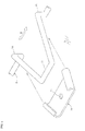
FIG. 3 is a perspective view showing one conductive wire applied to a bus ring of an embodiment of the present invention; -
FIG. 4 is an exploded perspective view of a usage example of bent portions of a bus ring of an embodiment of the present invention; -
FIG. 5 is an exploded perspective view showing a major part of a fixing structure of a bus ring of an embodiment of the present invention; -
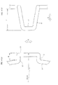
FIG. 6(a) is a plan view of bent portions of a bus ring of an embodiment of the present invention; and -
FIG. 6(b) is a side view thereof. -
FIG.1 shows a ring-shaped stator 3 turning anend face 1 thereof toward an axial direction of a rotary electrical machine pointed by an arrow S and abus ring 5 attached to thestator 3 along the end face of thestator 3. In thestator 3, a plurality ofstator teeth 7 are aligned in a circumferential direction indicated by an arrow R.FIG. 2 shows thebus ring 5 removed from thestator 3. Although the aforementioned rotary electrical machine is not shown in figure due to obvious art, the rotary electrical machine may house thestator 3 inside the housing and rotate an output shaft together with a rotor. - As shown in
FIG. 2 , thebus ring 5 includes fourconductive wires 9 curbed in the shape of an arc. As shown inFIG. 3 , each of theconductive wires 9 has a plurality of staple-shaped bent portions 11 protruding in an axial direction. The shape of an arc herein means a shape following a circle having a diameter of "φ" The symbol "φ" indicates the diameter of each of theconductive wires 9 and is set to be smaller than the diameter of an outercircumferential surface 13 of thestator 3 shown inFIG. 1 . The material for each of theconductive wires 9 is a conductor made of copper or the like and a surface of each of theconductive wires 9 may be covered with an insulating material. The cross section of each of theconductive wires 9 may be in the shape of a circle, an ellipse or a polygon. - Further, each of the
conductive wires 9 may have extendingportions 15 extending in a radial direction thereof andbent portions 11 respectively interposed between the extendingportions 15. In this case, the diameter [φ max] of a circle circumscribing the outermost side of the radial direction of each of theconductive wires 9 is preferably smaller than the diameter of the outercircumferential surface 13 of thestator 3. - The
bent portions 11 are portions to whichwindings 17 would around thestator teeth 7 shown inFIG. 1 are connected, therefore, it is possible to attach fittings or the like for screwing ends of thewindings 17. As shown inFIG. 4 , the width of the circumferential direction of abent portion 11 is preferably reducing gradually as thebent portion 11 protrudes in the axial direction. For example, in the case where a fitting 19 with both sides bent into a hook is subject to resistance welding to thebent portion 11, it is possible to nip thebent portion 11 inside the fitting 19 simply by allowing thebent portion 11 to enter inside the fitting 19. This enables easy positioning of the fitting 19 relative to thebent portion 11. And the fitting 19 has ahole 21 and the ends of the winding 17 are connected to the fitting 19 in a manner which will be described later. - As mentioned above, work for positioning the fitting 19 in the
bent portion 11 and work for connecting the winding 17 to the fitting 19 can be done from outward of the radial direction of thestator 3. This makes an operator possible to smoothly connect the winding 17 to the fitting 19 without blocking the operator's hands by thestator 3. Moreover, the operator is able to connect thewindings 17 to all of thebent portions 11 in the same manner because it is possible to do the aforementioned work from a front surface of each of thebent portions 11. As a result, it is easy to finish all places where the ends of thewindings 17 are connected to theconductive wires 9 in high quality. - The number of the
conductive wires 9 shown inFIGs. 1 and2 is set to be four because each of thewindings 17 in the U-phase, V-phase, W-phase, and N-phase of the rotary electrical machine is connected to oneconductive wire 9. In addition, thebus ring 5 may have one or moreconductive wires 9 and the number of theconductive wires 9 may be increased or decreased according to the specifications of the rotary electrical machine. - Next, a fixing
structure 23 of a bus ring for attaching one or a plurality ofconductive wires 9 to thestator 3 will now be described based onFIGs. 1 and5 . Aninsulator 25 is interposed between astator tooth 7 and a winding 17. This point is applied to allstator teeth 7.Insulators 25 are respectively a bobbin made of a synthesized resin around which thewindings 17 are wound and respectively have asupport 27 protruding in the axial direction from theend face 1 of thestator 3. Alternatively, only supports 27 of theinsulators 25 may be respectively made of a synthesized resin and thesupports 27 and separated insulating paper may wrap thestator 3. -
Respective supports 27 of a plurality ofinsulators 25 shown inFIG. 1 are arranged in a cylindrical shape to enter inside theconductive wires 9. Since theconductive wires 9 are supported by theinsulators 25 in this state, a holder or the like to attach theconductive wires 9 to thestator 3 is not needed. As a result, it is possible to reduce the number of parts for the rotary electrical machine. While the means for fixing theconductive wires 9 to theinsulators 25 is not particularly limited, windingfittings 30 respectively having screw holes 31 andterminals 32 may be fixed to thesupports 27 of theinsulators 25. And then a screw is put through thehole 21 of the fitting 19 shown inFIG. 4 to be screwed up to the screw holes 31 of the windingfittings 30. This allows the fitting 19 positioned in theconductive wire 9 to be fixed to thesupport 27 through a windingfitting 30. Theterminals 32 of the windingfittings 30 are portions to connect the ends of thewindings 17. Anumerical symbol 29 indicates a claw for positioning theconductive wires 9 in thesupports 27 by engaging claws into the inside of thebent portions 11. - Furthermore, there is no possibility of each of the
conductive wires 9 protruding in the radial direction of thestator 3 because it is possible to align the plurality ofconductive wires 9 in the axial direction even though the number of the plurality ofconductive wires 9 is increased or decreased. Consequently, the housing for a rotary electrical machine having a minimum inner diameter that enables thestator 3 to be housed may be sufficient, resulting in downsizing of the whole rotary electrical machine. In addition, there is an advantage of no need for enlarging the diameter of each of theconductive wires 9 for each protruded portion of thebent portions 11 to allow each of thesupports 27 of theinsulators 25 to enter inside each of theconductive wires 9 because thebent portions 11 protrude in an axial direction from theconductive wires 9. - According to the fixing
structure 23 of the bus ring, it is possible to avoid thebent portions 11 being overlapped to each other by aligning the positions of the respectivebent portions 11 of the plurality of theconductive wires 9. Accordingly, when each of thewindings 17 is connected to onebent portion 11 of one conductive wire out of the plurality ofconductive wires 9, there is no possibility of thebent portions 11 of one conductive wire out of the plurality of theconductive wires 9 being blocked by thebent portions 11 of the otherconductive wires 9. - Additionally, as shown in
FIGs. 6(a) and 6(b) , [d] denotes a length in which an extendingportion 15 extends in a radial direction thereof and [s] denotes a length in which abent portion 11 protrudes in an axial direction thereof. The plurality ofconductive wires 9 supported by theinsulators 25 respectively have the length [d] of the extendingportion 15. Therefore, as shown inFIGs. 1 and2 , an insulation distance essential to insulation is kept between thebent portions 11 of one conductive wire out of the plurality ofconductive wires 9 and the otherconductive wires 9. Consequently, according to the fixingstructure 23 of the bus ring, it is not necessary for the rotary electrical machine to be excessively long in the axial direction, resulting in downsizing of the rotary electrical machine. Further, as shown inFIG. 1 , it is possible to uniformly align space between theend face 1 of thestator 3 and thebent portions 11 of each of theconductive wires 9 by lengthen the length [s] of thebent portions 11 as a conductive wire out of the plurality ofconductive wires 9 being relatively spaced away from theend face 1 of thestator 3. - It is to be understood that the present invention may be practiced in an embodiment in which various modifications, alterations or variations are added based on knowledge of a person having ordinary skill in the art without departing the spirits and scope of the present invention. For instance, extending
portions 15 may be omitted in thebus ring 5. Further, the number of thebent portions 11 included in oneconductive wire 9 is not limited. - The present invention is applicable to rotary electrical machines.
- 1:end face; 3: stator; 5: bus ring: 7: stator tooth; 9: conductive wire; 11: bent portion; 13: outer circumferential surface: 15: extending portion; 17: winding; 19: fitting; 21: hole; 23: fixing structure of bus ring; 25: insulator; 27: support; 30: winding fitting; 31: screw hole; 32: terminal
Claims (7)
- A bus ring (5) attached to a stator (3) having a plurality of stator teeth (7) aligned in a circumferential direction and turning an end face (1) thereof toward an axial direction of a rotary electrical machine along the end face (1), the bus ring (5) being made by curving a conductive wire (9) in an arc shape with a diameter smaller than that of the stator (3),
wherein staple-shaped bent portions (11) protruding in the axial direction are formed at the conductive wire (9), and a winding (17) wound around each of the plurality of stator teeth (7) is connected to the bent portions (11). - The bus ring (5) according to claim 1, wherein a plurality of conductive wires (9) are respectively aligned in the axial direction.
- The bus ring (5) according to claim 2, wherein respective bent portions (11) of the plurality of conductive wires (9) are positioned in the circumferential direction.
- The bus ring (5) according to claim 2 or claim 3,
wherein extending portions (15) bent so as to respectively extend in a radial direction are formed at the plurality of conductive wires (9) and the bent portions (11) are formed at the conductive wires (9) so as to be interposed between the extending portions (15). - The bus ring (5) according to any one of claims 1 to 4, wherein the bent portions (11) respectively have a smaller width of the circumferential direction as the bent portions (11) protrude in the axial direction.
- A fixing structure (23) of a bus ring (5) for attaching a bus ring (5) to a stator (3) having a plurality of stator teeth (7) aligned in a circumferential direction and turning an end face (1) of the stator (3) toward an axial direction of a rotary electrical machine along the end face (1),
wherein the bus ring (5) is made by curving a conductive wire (9) in an arc shape with a diameter smaller than that of the stator (3), in which staple-shaped bent portions (11) protruding in the axial direction are formed at the conductive wire (9) and a winding (17) wound around each of the stator teeth (7) is connected to the bent portions (11), and
further wherein an insulator (25) extending in the axial direction from the end face (1) of the stator (3) is interposed between each of the stator teeth (7) and the winding (17) in the stator (3) to enter the insulator (25) inside the conductive wire (9). - The fixing structure (23) according to claim 6,
wherein the insulator (25) supports the plurality of conductive wires (9) at positions spaced away from the end face (1) of the stator (3) in the axial direction and respective bent portions (11) of the plurality of conductive wires (9) are different in length of protrusion of the bent portions (11) in the axial direction.
Applications Claiming Priority (2)
| Application Number | Priority Date | Filing Date | Title |
|---|---|---|---|
| JP2009069790A JP4636192B2 (en) | 2009-03-23 | 2009-03-23 | Bus ring and its mounting structure |
| PCT/JP2010/054109 WO2010110082A1 (en) | 2009-03-23 | 2010-03-11 | Bus ring, and fixing structure thereof |
Publications (2)
| Publication Number | Publication Date |
|---|---|
| EP2413479A1 true EP2413479A1 (en) | 2012-02-01 |
| EP2413479A4 EP2413479A4 (en) | 2017-01-18 |
Family
ID=42780775
Family Applications (1)
| Application Number | Title | Priority Date | Filing Date |
|---|---|---|---|
| EP10755882.7A Withdrawn EP2413479A4 (en) | 2009-03-23 | 2010-03-11 | Bus ring, and fixing structure thereof |
Country Status (6)
| Country | Link |
|---|---|
| US (1) | US8952583B2 (en) |
| EP (1) | EP2413479A4 (en) |
| JP (1) | JP4636192B2 (en) |
| KR (1) | KR101224332B1 (en) |
| CN (1) | CN102334264B (en) |
| WO (1) | WO2010110082A1 (en) |
Cited By (2)
| Publication number | Priority date | Publication date | Assignee | Title |
|---|---|---|---|---|
| EP2765687A3 (en) * | 2013-02-08 | 2016-10-05 | Hitachi Metals, Ltd. | Electricity collection and distribution ring and method of manufacturing the same |
| WO2019179558A1 (en) * | 2018-03-20 | 2019-09-26 | Schaeffler Technologies AG & Co. KG | Connection of "n"-busbars in an electric motor |
Families Citing this family (11)
| Publication number | Priority date | Publication date | Assignee | Title |
|---|---|---|---|---|
| JP5259778B2 (en) * | 2011-06-23 | 2013-08-07 | 達昭 浦谷 | Busbar and stator |
| JP5930801B2 (en) * | 2012-03-30 | 2016-06-08 | 日立オートモティブシステムズ株式会社 | In-vehicle motor and electric power steering apparatus using the same |
| WO2014020755A1 (en) * | 2012-08-03 | 2014-02-06 | 三菱電機株式会社 | Rotating electrical machine |
| CN104641540B (en) * | 2012-11-19 | 2018-02-16 | 三菱电机株式会社 | The rotor and its manufacture method of electric rotating machine |
| JP6113607B2 (en) | 2013-08-27 | 2017-04-12 | 日立金属株式会社 | Power collection / retention member holding structure, electric motor, and electric motor manufacturing method |
| JP6098589B2 (en) * | 2014-08-08 | 2017-03-22 | トヨタ自動車株式会社 | Rotating electrical machine stator |
| JP6160635B2 (en) * | 2015-02-16 | 2017-07-12 | 日立金属株式会社 | Power collection and distribution ring and electric motor |
| JP6124493B1 (en) * | 2015-06-05 | 2017-05-10 | デンソートリム株式会社 | Rotating electric machine for internal combustion engine and stator thereof |
| CN107979204B (en) * | 2017-12-27 | 2023-12-05 | 五羊—本田摩托(广州)有限公司 | Motor stator and motor |
| JP6676099B2 (en) * | 2018-05-18 | 2020-04-08 | 三菱電機株式会社 | Rotating electric machine |
| JP7089939B2 (en) | 2018-05-22 | 2022-06-23 | Ntn株式会社 | Motors and vehicle power units equipped with this motor, generators and bearings for wheels with generators equipped with this generator |
Family Cites Families (13)
| Publication number | Priority date | Publication date | Assignee | Title |
|---|---|---|---|---|
| JPH1118331A (en) * | 1997-06-30 | 1999-01-22 | Matsushita Electric Ind Co Ltd | Motor stator |
| JP3535452B2 (en) * | 2000-06-28 | 2004-06-07 | 株式会社日立製作所 | DC brushless motor |
| JP3701639B2 (en) * | 2002-08-29 | 2005-10-05 | 本田技研工業株式会社 | Electric motor lead frame and power distribution parts using the same |
| DE10261611A1 (en) * | 2002-12-27 | 2004-07-08 | Robert Bosch Gmbh | Connection element for a winding of an electrical machine |
| JP4332128B2 (en) | 2005-04-12 | 2009-09-16 | 本田技研工業株式会社 | Motor stator structure |
| JP4684023B2 (en) * | 2005-06-29 | 2011-05-18 | 住友電装株式会社 | Centralized power distribution member for thin brushless motor for vehicles |
| DE202005011721U1 (en) * | 2005-07-27 | 2006-12-07 | Ebm-Papst Mulfingen Gmbh & Co. Kg | Stator of an electric motor with winding wiring arrangement |
| JP4149474B2 (en) | 2005-10-07 | 2008-09-10 | 本田技研工業株式会社 | Stator and manufacturing method thereof |
| CN101694954B (en) * | 2006-07-04 | 2012-07-25 | 本田技研工业株式会社 | Motor stator structure |
| JP4914287B2 (en) * | 2007-05-02 | 2012-04-11 | 住友電気工業株式会社 | Insulator, split stator, and stator for rotating electrical machine |
| WO2009025144A1 (en) * | 2007-08-17 | 2009-02-26 | Kabushiki Kaisha Yaskawa Denki | Stator and rotating electrical machine using the same |
| JP5178292B2 (en) * | 2008-04-15 | 2013-04-10 | 本田技研工業株式会社 | Current collection and distribution structure of rotating electrical machines |
| US8154163B2 (en) * | 2008-04-15 | 2012-04-10 | Honda Motor Co., Ltd. | Electric power collection/distribution ring of rotary electric machine |
-
2009
- 2009-03-23 JP JP2009069790A patent/JP4636192B2/en active Active
-
2010
- 2010-03-11 WO PCT/JP2010/054109 patent/WO2010110082A1/en not_active Ceased
- 2010-03-11 CN CN2010800098758A patent/CN102334264B/en not_active Expired - Fee Related
- 2010-03-11 EP EP10755882.7A patent/EP2413479A4/en not_active Withdrawn
- 2010-03-11 KR KR1020117018566A patent/KR101224332B1/en not_active Expired - Fee Related
- 2010-03-11 US US13/258,774 patent/US8952583B2/en not_active Expired - Fee Related
Non-Patent Citations (1)
| Title |
|---|
| See references of WO2010110082A1 * |
Cited By (2)
| Publication number | Priority date | Publication date | Assignee | Title |
|---|---|---|---|---|
| EP2765687A3 (en) * | 2013-02-08 | 2016-10-05 | Hitachi Metals, Ltd. | Electricity collection and distribution ring and method of manufacturing the same |
| WO2019179558A1 (en) * | 2018-03-20 | 2019-09-26 | Schaeffler Technologies AG & Co. KG | Connection of "n"-busbars in an electric motor |
Also Published As
| Publication number | Publication date |
|---|---|
| CN102334264B (en) | 2013-12-18 |
| CN102334264A (en) | 2012-01-25 |
| JP2010226832A (en) | 2010-10-07 |
| EP2413479A4 (en) | 2017-01-18 |
| KR20110114630A (en) | 2011-10-19 |
| WO2010110082A1 (en) | 2010-09-30 |
| KR101224332B1 (en) | 2013-01-21 |
| US8952583B2 (en) | 2015-02-10 |
| US20120013210A1 (en) | 2012-01-19 |
| JP4636192B2 (en) | 2011-02-23 |
Similar Documents
| Publication | Publication Date | Title |
|---|---|---|
| US8952583B2 (en) | Bus ring, and fixing structure thereof | |
| EP3007319B1 (en) | Rotary electric machine, and manufacturing method therefor | |
| US9079603B2 (en) | Motor for an electric power steering apparatus | |
| EP2611000B1 (en) | Electric motor | |
| US8154163B2 (en) | Electric power collection/distribution ring of rotary electric machine | |
| EP2833520B1 (en) | Stator | |
| EP3193428B1 (en) | Stator | |
| EP2833521A1 (en) | Stator | |
| WO2015097753A1 (en) | Rotating electrical machine | |
| JP2016059130A (en) | Rotating electric machine stator | |
| JP2007174869A (en) | Insulator, stator assembly, segment stator, and stator for rotating electrical machine | |
| JP4971025B2 (en) | Stator for rotating electrical machine | |
| US10348149B2 (en) | Stator for rotating electric machine and rotating electric machine including the stator | |
| EP4084299A1 (en) | Coil, stator comprising same, and motor | |
| EP3079233A1 (en) | Electric power collection/distribution ring and electric motor | |
| JP2019135903A (en) | Armature of rotary electric machine and rotary electric machine | |
| EP3285366A1 (en) | Stator and method of manufacturing stator | |
| JP4986974B2 (en) | Stator | |
| JP2012105372A (en) | Outer rotor type electric motor | |
| EP3276798B1 (en) | Stator | |
| JP2007259523A (en) | Stator and insulator for rotating electrical machine | |
| JP6656366B2 (en) | Rotating electric machine rotor | |
| JP2016052234A (en) | Manufacturing method of rotary electric machine stator with lead wire | |
| EP3373420A1 (en) | Rotor of rotating electric machine | |
| US20250047165A1 (en) | Motor |
Legal Events
| Date | Code | Title | Description |
|---|---|---|---|
| PUAI | Public reference made under article 153(3) epc to a published international application that has entered the european phase |
Free format text: ORIGINAL CODE: 0009012 |
|
| 17P | Request for examination filed |
Effective date: 20111010 |
|
| AK | Designated contracting states |
Kind code of ref document: A1 Designated state(s): AT BE BG CH CY CZ DE DK EE ES FI FR GB GR HR HU IE IS IT LI LT LU LV MC MK MT NL NO PL PT RO SE SI SK SM TR |
|
| DAX | Request for extension of the european patent (deleted) | ||
| RA4 | Supplementary search report drawn up and despatched (corrected) |
Effective date: 20161221 |
|
| RIC1 | Information provided on ipc code assigned before grant |
Ipc: H02K 3/52 20060101AFI20161215BHEP Ipc: H02K 3/46 20060101ALI20161215BHEP Ipc: H02K 3/18 20060101ALI20161215BHEP |
|
| STAA | Information on the status of an ep patent application or granted ep patent |
Free format text: STATUS: THE APPLICATION IS DEEMED TO BE WITHDRAWN |
|
| 18D | Application deemed to be withdrawn |
Effective date: 20170720 |