JP5259778B2 - Busbar and stator - Google Patents
Busbar and stator Download PDFInfo
- Publication number
- JP5259778B2 JP5259778B2 JP2011139758A JP2011139758A JP5259778B2 JP 5259778 B2 JP5259778 B2 JP 5259778B2 JP 2011139758 A JP2011139758 A JP 2011139758A JP 2011139758 A JP2011139758 A JP 2011139758A JP 5259778 B2 JP5259778 B2 JP 5259778B2
- Authority
- JP
- Japan
- Prior art keywords
- bus bar
- phase
- coil connection
- coil
- circular
- Prior art date
- Legal status (The legal status is an assumption and is not a legal conclusion. Google has not performed a legal analysis and makes no representation as to the accuracy of the status listed.)
- Active
Links
Images


Landscapes
- Motor Or Generator Frames (AREA)
- Windings For Motors And Generators (AREA)
- Insulation, Fastening Of Motor, Generator Windings (AREA)
Description
本発明は、バスバー及びステータに関する。 The present invention relates to a bus bar and a stator.
電動モータとして、円筒形のステーターコイルと、ステーターコイルの内側に配置された円柱形のローターと、ローターに接続されているシャフトから構成されたものが知られており、ステーターコイルとしては、内歯形状のステータ鉄心の内歯に、ステータ鉄心の径方向内側から捲線を捲き付けて構成したものがある。 As an electric motor, a motor composed of a cylindrical stator coil, a cylindrical rotor arranged inside the stator coil, and a shaft connected to the rotor is known. There is one in which the inner teeth of the shaped stator iron core are wound with a winding from the inside in the radial direction of the stator iron core.
このような電動モータとしては、U相、V相、W相からなる3相のコイル群により回転磁界を形成するモータが知られている。そして、これら各相のコイル群から導出される導電線の結線は、バスバーを利用して行われている(例えば、特許文献1参照)。 As such an electric motor, a motor that forms a rotating magnetic field by a three-phase coil group including a U phase, a V phase, and a W phase is known. And the connection of the conductive wire derived | led-out from these coil groups of each phase is performed using the bus bar (for example, refer patent document 1).
しかしながら、上記バスバーは金属板を打ち抜いて作製しているため、材料を捨てる部分が生じ、歩留まりが悪かった。 However, since the bus bar is manufactured by punching a metal plate, a portion for discarding the material is generated, and the yield is poor.
一方、この問題を解決するために、丸線によってバスバーを作製することも考えられるが、占積率が悪くなるという問題が生じる。 On the other hand, in order to solve this problem, it is conceivable to make a bus bar with a round wire, but there arises a problem that the space factor deteriorates.
本発明は、歩留まりの良好な又は占積率の良好なバスバー及びステータを提供することを目的とする。 An object of the present invention is to provide a bus bar and a stator having a good yield or a good space factor.
上記目的を達成するために、第1の本発明は、
複数のコイルの一端同士を接続する、一本の平角線で円状又は円弧状に形成されたバスバーであって、
前記平角線の一端から他端の間に形成された、前記コイルの一端と接続する複数のコイル接続部と、
隣り合う前記コイル接続部の間に形成された渡り部とを備え、
前記コイル接続部では、前記平角線の一部において、前記平角線の主面同士が重なっている、バスバーである。
In order to achieve the above object, the first present invention provides:
A bus bar that connects one end of a plurality of coils and is formed in a circular or arc shape with a single rectangular wire,
A plurality of coil connecting portions formed between one end of the flat wire and the other end, connected to one end of the coil;
A transition portion formed between adjacent coil connection portions,
The coil connecting portion is a bus bar in which main surfaces of the rectangular wires overlap each other in a part of the rectangular wires.
第2の本発明は、
前記平角線の主面同士は、前記平角線が折り曲げられて重なっており、
折り目の部分に、切り欠き部が形成されている、第1の本発明のバスバーである。
The second aspect of the present invention
The main surfaces of the flat wire are overlapped by bending the flat wire,
The bus bar according to the first aspect of the present invention, wherein a notch is formed at a fold.
第3の本発明は、
前記コイル接続部は、
前記円状又は前記円弧状の軸と平行な方向に形成されている、第1の本発明のバスバーである。
The third aspect of the present invention provides
The coil connection part is
It is the bus bar of the first aspect of the present invention formed in a direction parallel to the circular or arcuate axis.
第4の本発明は、
前記コイル接続部は、
前記円状又は前記円弧状の内側に向かって形成されている、第1の本発明のバスバーである。
The fourth invention relates to
The coil connection part is
It is a bus bar according to the first aspect of the present invention, which is formed toward the inside of the circular shape or the circular arc shape.
第5の本発明は、
前記平角線は、隣り合う前記渡り部のうち一方の前記渡り部において、その両主面のうち一方の主面が前記円状又は前記円弧状の外周側を向き、他方の主面が前記円状又は円弧状の内周側を向くように配置されており、他方の前記渡り部において、前記一方の主面が前記円状又は前記円弧状の内周側を向き、前記他方の主面が前記円状又は前記円弧状の外周側を向くように配置されている、第1の本発明のバスバーである。
The fifth aspect of the present invention relates to
The rectangular wire has one main surface of the two crossing portions facing the circular or arcuate outer peripheral side, and the other main surface of the crossing portion of the crossing portions adjacent to each other. Is arranged so as to face the inner peripheral side of the circular or arc shape, and in the other transition portion, the one main surface faces the inner peripheral side of the circular or arc shape, and the other main surface is It is the bus bar according to the first aspect of the present invention, which is arranged so as to face the outer circumference side of the circular shape or the circular arc shape.
第6の本発明は、
前記平角線の外周には、ポリイミドおよびテフロン(登録商標)の2層で形成された薄膜の絶縁テープが、加熱して密着するように横巻に巻き付けられている、第1の本発明のバスバーである。
The sixth invention relates to
A bus bar according to the first aspect of the present invention, in which a thin-film insulating tape formed of two layers of polyimide and Teflon (registered trademark) is wound in a lateral winding so as to be heated and adhered to the outer periphery of the rectangular wire It is.
第7の本発明は、
ステータコアと、
前記ステータコアのティースに配置された複数のU相コイルと、
前記ステータコアのティースに配置された複数のV相コイルと、
前記ステータコアのティースに配置された複数のW相コイルと、
前記複数のU相コイルを接続するU相バスバーと、
前記複数のV相コイルを接続するV相バスバーと、
前記複数のW相コイルを接続するW相バスバーと、
前記複数のU相コイル、前記複数のV相コイル、及び複数のW相コイルを中性点に接続する中性バスバーとを備え、
前記U相バスバー、前記V相バスバー、前記W相バスバー、及び前記中性バスバーのうち少なくとも1つに第1の本発明のバスバーが用いられている、ステータである。
The seventh invention relates to
A stator core;
A plurality of U-phase coils arranged on the teeth of the stator core;
A plurality of V-phase coils disposed on the teeth of the stator core;
A plurality of W-phase coils disposed on the teeth of the stator core;
A U-phase bus bar connecting the plurality of U-phase coils;
A V-phase bus bar connecting the plurality of V-phase coils;
A W-phase bus bar connecting the plurality of W-phase coils;
A neutral bus bar that connects the plurality of U-phase coils, the plurality of V-phase coils, and the plurality of W-phase coils to a neutral point;
A stator in which the bus bar according to the first aspect of the present invention is used for at least one of the U-phase bus bar, the V-phase bus bar, the W-phase bus bar, and the neutral bus bar.
本発明によれば、歩留まりの良好な又は占積率の良好なバスバー及びステータを提供することが出来る。 According to the present invention, it is possible to provide a bus bar and a stator having a good yield or a good space factor.
以下、本発明にかかる実施の形態について図面を参照しながら説明する。 Embodiments of the present invention will be described below with reference to the drawings.
(実施の形態1)
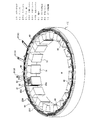
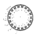
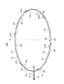
以下に、本発明にかかる実施の形態1におけるステータについて説明する。図1は、本実施の形態1のステータの斜視構成図である。又、図2は、本実施の形態1のステータの平面構成図である。
(Embodiment 1)
Below, the stator in
図1及び図2に示すステータは、U相、V相、W相の3相モータ用のステータであり、18個のティース11を有するステータコア10と、それぞれのティース11に巻き付けられて形成されたコイル20(U相コイル20U、V相コイル20V、及びW相コイル20W)と、U相バスバー30U、V相バスバー30V、及びW相バスバー30Wと、6つの中性バスバー40とを備えている。尚、図1には1個のU相コイル20Uのみ図示されている。
The stator shown in FIG. 1 and FIG. 2 is a stator for a U-phase, V-phase, and W-phase three-phase motor, and is formed by winding a
U相コイル20U、V相コイル20V、及びW相コイル20Wは、同じ構成であり、丸線を捲き回すことによって形成され、この順に図2中時計回りにそれぞれのティース11に配置されている。
The
上記U相コイル20U、V相コイル20V、及びW相コイル20Wは、それぞれ6個ずつ設けられている。そして、6個のU相コイル20Uのそれぞれの端21がU相バスバー30Uに電気的に接続されており、それぞれの端22は、中性バスバー40に電気的に接続されている。同様に、6個のV相コイル20Vのそれぞれの端21がV相バスバー30Vに電気的に接続されており、それぞれの端22は、中性バスバー40に電気的に接続されている。又、6個のW相コイル20Wのそれぞれの端21がW相バスバー30Wに電気的に接続されており、それぞれの端22は、中性バスバー40に電気的に接続されている。
Six
次に、本発明にかかる実施の形態1のバスバーの構成について説明するが、U相バスバー30Uと、V相バスバー30Vと、W相バスバー30Wは、同様の構成であるため、U相バスバー30Uを例に挙げて説明する。
Next, the configuration of the bus bar according to the first embodiment of the present invention will be described. The
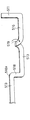
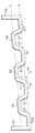
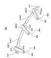
図3は、本実施の形態1のU相バスバー30Uの斜視構成図である。図3に示すように、本実施の形態1のU相バスバー30Uは、一本の平角線50によって、ステータコア10の外周に沿うように円状に形成されている。この平角線50の一端51と他端52は重なり合って、外周側に折り曲げられており、U相バスバー30Uの端子31を構成している。
FIG. 3 is a perspective configuration diagram of the
又、平角線50の一端51から他端52までの間には、6個のU相コイル20Uの端21を繋ぐための6個のコイル接続部32が形成されている。図3において、これらのコイル接続部32には、括弧内に一端51から何番目のコイル接続部312であるかを示すために番号がふられている。すなわち、6個のコイル接続部312は、時計回りに、一端51からコイル接続部32(1)、32(2)、32(3)、32(4)、32(5)、32(6)の順に他端52まで繋がっている。
Further, six
そして、これらコイル接続部32の間には、コイル接続部32同士を繋ぐ渡り部33が形成されている。尚、一端51と一端51側の端のコイル接続部32の間の線材部分は、渡り部36として図示され、他端52と他端52側の端のコイル接続部32の間の線材部分は、渡り部37として図示されている。
And between these
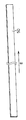
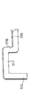
図4は、図3のS部の拡大図であり、コイル接続部32(5)近傍の拡大斜視構成図である。中心側(軸M側)から視て(矢印A参照)、コイル接続部32の左隣の渡り部33(L)では、平角線50の一方の主面50aが円状の外周側を向き、他方の主面50bが円状の内周側を向いている。そして、平角線50がエッジワイズに曲げられて、折り返される。このように折り返されることによって、コイル接続部32では、平角線50の一部において主面50b同士が重なることになる。尚、エッジワイズとは、平角線50の主面50a、50bは曲がる前後で同一面に位置し、端面50eが曲がる前後で同一面に位置しないように、平角線50が曲げられることである。いいかえると、端面50eに折り目が形成されるように平角線50が曲げられることである。
FIG. 4 is an enlarged view of the S part of FIG. When viewed from the center side (axis M side) (see arrow A), at the crossing portion 33 (L) adjacent to the left of the
コイル接続部32から、更に平角線50がエッジワイズに曲げられて、中心側から視てコイル接続部32の右隣の渡り部33(R)が形成されている。このため、コイル接続部32の右隣の渡り部33では、主面50bが円状の外周側を向き、主面50aが円状の内周側を向いている。このように、コイル接続部32を挟んで隣り合う渡り部33では、平角線50の主面50aと主面50bの向きが反対になっている。
The
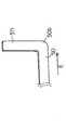
そして、コイル接続部32(2)は、円状の軸(図1、図3中M参照)と平行な方向に向かって左右の渡り部33から突出しており、その突出した先端部34には、切り欠き部35が形成されている。この切り欠き部35に、U相コイル20Uの端21が挿入されて接続される
又、実施の形態1では、中心側から視て、コイル接続部32(2)の左隣の渡り部33と繋がっている部分38が、右側の渡り部33と繋がっている部分39より外周側(図中奥側)に位置している。
And the coil connection part 32 (2) protrudes from the left and
尚、他の全てのコイル接続部32(1)、32(3)、32(4)、32(5)、32(6)は、コイル接続部32(2)と同様に構成されている。又、コイル接続部32(1)では、中心側から視て左側には、渡り部36は配置されており、コイル接続部32(6)では、左隣には、渡り部37が配置されている。
又、本発明の折り目の一例は、本実施の形態の先端部34に対応する。
In addition, all the other coil connection parts 32 (1), 32 (3), 32 (4), 32 (5), 32 (6) are comprised similarly to the coil connection part 32 (2). Further, in the coil connection portion 32 (1), a
An example of the fold line of the present invention corresponds to the
尚、本実施の形態1のU相バスバー30U、V相バスバー30V、及びW相バスバー30Wは、図2に示すように時計回りにずらして配置されており、最も内周側にU相バスバー30Uが配置され、次にV相バスバー30Vが配置され、最も外側にW相バスバー30Wが配置されている。尚、本発明の円状に形成されたバスバーの一例は、本実施の形態のU相バスバー30U、V相バスバー30V、及びW相バスバー30Wに対応する。
The
次に、中性バスバー40の構成について説明する。
Next, the configuration of the
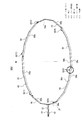
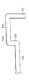
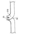
図5は、中性バスバー40の斜視構成図である。図2及び図5に示すように6個の中性バスバー40は、ステータコア10の外周に沿うように湾曲して円弧状に形成されている。
図5に示す中性バスバー40は、それぞれ3つのコイル接続部42と、コイル接続部42の間を電気的に繋ぐ渡り部43とを備えている。尚、中心から視て(矢印A参照)、最も左側のコイル接続部42の端には、端部46が形成されており、最も右側のコイル接続部42の端には、端部47が形成されている。これらコイル接続部42は、実施の形態1と同様に、円弧状の軸(図1中M参照)と平行な方向に向かって形成されており、渡り部43の構成も実施の形態1と同様の構成である。また、コイル接続部42は、コイル接続部32と同様に先端部44に切り欠き部45が形成されている。
FIG. 5 is a perspective configuration diagram of the
Each
ここで、端部46の側から1番目、2番目、3番目のコイル接続部42を42(1)、42(2)、42(3)と符号を付し、渡り部43を43(1)、43(2)と符号を付す。
Here, the first, second, and third
コイル接続部42(1)の端部46と繋がっている部分48は、コイル接続部42(1)の渡り部43(1)と繋がっている部分49より、外周側に位置している。コイル接続部42(2)の渡り部43(1)と繋がっている部分48は、コイル接続部42(2)の渡り部43(2)と繋がっている部分49より、外周側に位置している。コイル接続部42(3)の渡り部43(2)と繋がっている部分48は、コイル接続部42(3)の端部47と繋がっている部分49より、外周側に位置している。このように、いずれのコイル接続部42(1)、42(2)、42(3)も同様に構成されている。
The
そして、6個の中性バスバー40は、U相バスバー30Uよりも内側に配置されている。尚、本発明の円弧状に形成されたバスバーの一例は、本実施の形態の中性バスバー40に対応する。又、本発明の折り目の一例は、本実施の形態の先端部44に対応する。
The six neutral bus bars 40 are arranged inside the
尚、図2に示すように、6個のU相コイル20Uは、それぞれの端21がU相バスバー30Uのコイル接続部32に接続されており、それぞれの端22が中性バスバー40のコイル接続部42に接続されている。又、6個のV相コイル20Vは、それぞれの端21がV相バスバー30Vのコイル接続部32に接続されており、それぞれの端22が中性バスバー40のコイル接続部42に接続されている。そして、6個のW相コイル20Wは、それぞれの端21がW相バスバー30Wのコイル接続部32に接続されており、それぞれの端22が中性バスバー40のコイル接続部42に接続されている。又、図2において、括弧内のU、V、Wによって各相の端子31が示されている。このように、各相において6個のコイルが並列に接続されることになる。
As shown in FIG. 2, each of the six
次に、本発明にかかる実施の形態1のバスバーの製造方法について説明する。尚、上述したU相コイル20Uを例に挙げて説明する。
Next, the manufacturing method of the bus bar according to the first embodiment of the present invention will be described. The above-described
図6(a)〜(i)は、本実施の形態1のバスバーの製造方法を説明するための模式図である。 6 (a) to 6 (i) are schematic diagrams for explaining the bus bar manufacturing method according to the first embodiment.
図6(a)は、一本の平角線50を示している。この線材の方向が矢印Eで示されている。
FIG. 6A shows one
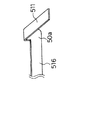
この平角線50が、図6(b)に示すように、矢印Eを基準にして、図中において、端部511がエッジワイズに上方に折り曲げられる。そして、平角線50は、折り曲げられた部分から直線状の線材部分516の間を空けて、図6(c)に示すように、エッジワイズにクランク状に曲げられる(図中クランク形状部518参照)。
As shown in FIG. 6 (b), the
続いて図6(d)に示すように、1つめのクランク形状部518から、直線の線材部分513の間を空けて、更にクランク形状部518が形成され、計6つのクランク形状部518が形成される。このように曲げることによって、矢印E方向と平行な2つの直線上(図中B、C参照)のそれぞれに配置された、複数の線材部分513、516が形成される。最後に、図6(e)に示すように、直線状の線材部分517を空けて、図中において端部512がエッジワイズに下方に折り曲げられる。
Subsequently, as shown in FIG. 6 (d), a space between the
次に、図6(f)に示すように、端部511から一つ目のクランク形状部518は、その上部518a(図6(d)参照)が図中手前側に折り返される。ここで、線材部分516と線材部分513が、正面視において直線上になるように折り返され、折り返し部519が形成される。
Next, as shown in FIG. 6 (f), the first crank
続いて、図6(g)に示すように、端部511から2つ目のクランク形状部518は、その上部518a(図6(f)参照)が図中奥側に位置するように折り返され、折り返し部519が形成される。ここで、端部511から1つ目の線材部分513と2つ目の線材部分513が正面視において直線上に配置されるように折り返される。
Subsequently, as shown in FIG. 6G, the second crank-shaped
このように、6つのクランク形状部518が、奥側、手前側に交互に折り返され、6つの折り返し部519が形成される。
In this manner, the six crank-shaped
そして、図6(h)に示すように、各折り返し部519の折り目部分519a(図6(g)参照)に切り欠き部35が形成され、コイル接続部32が作製される。一方、端部511は、図6(i)に示すように、フラットワイズに折り返される。ここで、フラットワイズとは、主面に折り目が形成されるように曲げられることである(図6(i)中、主面50a参照)。尚、線材部分516は、図3の渡り部36に対応し、線材部分517は、図3の渡り部37に対応する。また、端部511は一端51に対応し、端部512は他端52に対応する。
Then, as shown in FIG. 6 (h), a
そして、図6(h)に示すようにコイル接続部32が形成された平角線50をステータコア10の外周に沿うように円状に湾曲させ、両端51、52によって端子31が形成され、図3に示すU相バスバー30Uが作製される。
Then, as shown in FIG. 6 (h), the
尚、V相バスバー30V、W相バスバー30W、及び中性バスバー40も同様に作製される。
The V-
このようにしてバスバーが作製された後、ステータコア10のティース11に配置されたコイル20の端21及び端22を切り欠き部35、45内に配置し、ヒュージングによって熱かしめを行うことによって、図1に示すようにコイルとバスバーの間の結線が行われ、本実施の形態1のステータが作製される。
After the bus bar is manufactured in this manner, the ends 21 and 22 of the coil 20 disposed in the
以上のように、本実施の形態1では、一本の平角線によってバスバーを作製しているため、捨てる部分がなく歩留まりが良好となる。又、平角線を用いているため、占積率も良好となる。 As described above, in the first embodiment, since the bus bar is manufactured by one flat wire, there is no portion to be discarded and the yield is improved. Moreover, since the rectangular wire is used, the space factor is also good.
(実施の形態2)
次に、本発明にかかる実施の形態2におけるバスバーについて説明する。本実施の形態2のバスバーは、実施の形態1と基本的な構成は同じであるが、一部のコイル接続部で、その形状が異なっている。そのため、本相違点を中心に説明する。尚、実施の形態1と同様の構成については同一の符号が付されている。
(Embodiment 2)
Next, the bus bar according to the second embodiment of the present invention will be described. The basic configuration of the bus bar of the second embodiment is the same as that of the first embodiment, but the shape of the bus bar is different at some coil connection portions. Therefore, this difference will be mainly described. In addition, the same code | symbol is attached | subjected about the structure similar to
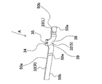
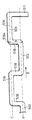
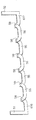
図7は、本実施の形態2のU相バスバー310Uの斜視構成図である。
FIG. 7 is a perspective configuration diagram of the
図7に示すように、本実施の形態2のU相バスバー310Uは、実施の形態1と同様に、一本の平角線50によって、ステータコア10の外周に沿うように円状に形成されている。この平角線50の一端51と他端52は重なり合って、外周側に折り曲げられており、U相バスバー30Uの端子31を構成している。
As shown in FIG. 7, the U-phase bus bar 310 </ b> U of the second embodiment is formed in a circular shape along the outer periphery of the
又、平角線50の一端51から他端52までの間には、6個のU相コイル20Uを繋ぐための6個のコイル接続部312が形成されている。図7において、これらのコイル接続部312は、括弧内に一端51から何番目のコイル接続部312であるかを示すために番号がふられている。すなわち、6個のコイル接続部312は、時計回りに、一端51からコイル接続部312(1)、312(2)、312(3)、312(4)、312(5)、312(6)の順に他端52まで繋がっている。
Further, six
そして、これらコイル接続部312の間には、コイル接続部312同士を繋ぐ渡り部313が形成されている。尚、一端51と一端51側の端のコイル接続部312の間の線材部分は、渡り部316として図示され、他端52と他端52側の端のコイル接続部312の間の線材部分は、渡り部317として図示されている。
And between these
図8(a)は、コイル接続部312(5)の拡大斜視構成図である。一方、図8(b)は、実施の形態1のコイル接続部32(5)の拡大斜視構成図であり、図4と同様の構成を示す図である。
FIG. 8A is an enlarged perspective configuration diagram of the coil connection portion 312 (5). On the other hand, FIG.8 (b) is an expansion perspective view of the coil connection part 32 (5) of
図7及び図8(a)に示すように、本実施の形態2のコイル接続部312は、実施の形態1のコイル接続部32と同様に、軸Mと平行に渡り部313から突出して形成されており、その先端部314に切り欠き部315が形成されている。
As shown in FIGS. 7 and 8A, the
又、図8(a)、(b)に示すように、実施の形態2では、内周側から視て(矢印A参照)、コイル接続部312(5)の左側の渡り部313と繋がっている部分318が、右側の渡り部313と繋がっている部分319より外周側に位置しており、実施の形態1と同様の構成である。すなわち、実施の形態1においても、コイル接続部32(5)の左側の渡り部33と繋がっている部分38が、右側の渡り部33と繋がっている部分39よりが外周側に位置している。
Further, as shown in FIGS. 8A and 8B, in the second embodiment, when viewed from the inner peripheral side (see arrow A), it is connected to the
尚、コイル接続部312(1)、(3)においても、同様に、中心側から視て、コイル接続部312の左側の渡り部313と繋がっている部分318が、右側の渡り部313と繋がっている部分319より外周側に位置しており、実施の形態1のコイル接続部32と同様の構成である。又、コイル接続部312(1)では、中心側から視て左側には、渡り部36が配置されている。
Similarly, in the coil connection portions 312 (1) and (3), the
図9(a)は、コイル接続部312(2)の拡大斜視図である。一方、図9(b)は、実施の形態1のコイル接続部32(2)の拡大斜視図である。図9(a)、(b)に示すように、実施の形態1では、円の中心側から視て(矢印A参照)、コイル接続部32(2)の左側の渡り部33と繋がっている部分38が、右側の渡り部33と繋がっている部分39より外周側に位置しているが、実施の形態2では、コイル接続部312(2)の左側の渡り部313と繋がっている部分318が、右側の渡り部313と繋がっている部分319より内周側に位置している。
FIG. 9A is an enlarged perspective view of the coil connecting portion 312 (2). On the other hand, FIG.9 (b) is an expansion perspective view of the coil connection part 32 (2) of
尚、コイル接続部312(4)、(6)においても、同様に、中心側から視て、コイル接続部312の左側の渡り部313と繋がっている部分318が、右側の渡り部313と繋がっている部分319より内周側に位置している。又、コイル接続部312(6)では、左隣には、渡り部37が配置されている。
Similarly, in the coil connection portions 312 (4) and (6), the
このように、本実施の形態2では、実施の形態1と異なり、コイル接続部312(2)、312(4)、312(6)において、コイル接続部312とその左側の渡り部313とが繋がっている部分318が、コイル接続部312とその右側の渡り部313とが繋がっている部分319よりも内周側に位置している。
As described above, in the second embodiment, unlike the first embodiment, in the coil connection portions 312 (2), 312 (4), and 312 (6), the
尚、本発明の円状のバスバーの一例は、本実施の形態のU相バスバー310Uに対応する。又、本発明の折り目の一例は、本実施の形態の先端部314に対応する。
An example of the circular bus bar of the present invention corresponds to the
図10は、本実施の形態の中性バスバー410の斜視構成図である。
FIG. 10 is a perspective configuration diagram of the
図10に示すように、本実施の形態2の中性バスバー410は、実施の形態1の中性バスバー40と同様に、3つのコイル接続部412、渡り部413、先端部414、切り欠き部415、及び端部416、417を備えている。ここで、端部416の側から1番目、2番目、3番目のコイル接続部412を412(1)、412(2)、412(3)と符号を付す。
As shown in FIG. 10, the
コイル接続部412(1)の端部416と繋がっている部分418は、コイル接続部412(1)の渡り部413と繋がっている部分419より、外周側に位置している。中心側から視て、コイル接続部412(2)とその左隣の渡り部413と繋がっている部分418は、コイル接続部412(2)とその右隣の渡り部413と繋がっている部分419より、内周側に位置している。コイル接続部412(3)の渡り部413と繋がっている部分418は、コイル接続部412(3)の端部417と繋がっている部分419より、外周側に位置している。
A
次に、本発明にかかる実施の形態2のバスバーの製造方法について説明する。 Next, the manufacturing method of the bus bar according to the second embodiment of the present invention will be described.
図11(a)〜(d)は、本実施の形態2のバスバーの製造方法を説明するための図である。図11(a)は、一本の平角線50を示している。この線材の方向が矢印Eで示されている。
FIGS. 11A to 11D are views for explaining a method of manufacturing the bus bar according to the second embodiment. FIG. 11A shows one
この平角線50が、図11(b)に示すように、概略、図中矢印E方向に沿うように、E方向を基準にして左右にエッジワイズに曲げられ、6つのクランク形状部57が形成される。このように曲げることによって、矢印E方向と平行な2つの直線上(図中B、C参照)のそれぞれに配置された、複数の線材部分55、56が形成される。尚、端部511、512部分は、矢印Eに対して垂直方向に形成されている。後述する工程によって、これら線材部分55、56は、渡り部33となる。また、端部511とクランク形状部57の間の線材部分616は、図7に示す渡り部316となり、端部512とクランク形状部57との間の線材部分617は、渡り部317となる
そして、図11(c)に示すように、線材部分56が、線材部分55と実質上同一直線上になるように折り曲げられる。これによって平角線50が重なった重なり部分58が6箇所形成される。
As shown in FIG. 11 (b), this
次に、図11(d)に示すように、重なり部分58の先端部分に切り欠き部35が形成され、コイル接続部32が形成される。そして、図11(d)に示す形状の平角線50をステータコア10の外周に沿うように円状に湾曲させ、両端51、52によって端子31が形成され、図7に示すU相バスバー310Uが作製される。
Next, as shown in FIG. 11 (d), the
尚、V相バスバー、W相バスバー、及び中性バスバーも同様に作製される。 A V-phase bus bar, a W-phase bus bar, and a neutral bus bar are similarly manufactured.
このようにしてバスバーが作製された後、ステータコア10のティース11に配置されたコイル20の端21及び端22を切り欠き部35、45内に配置し、ヒュージングによって熱かしめを行い、コイルとバスバーの間の結線が行われ、本実施の形態1のステータが作製される。
After the bus bar is manufactured in this way, the ends 21 and 22 of the coil 20 disposed in the
実施の形態1では、コイル接続部を1つずつ形成していく必要があったが、本実施の形態2では、線材部分56を折り曲げることによって2つのコイル接続部を簡単に形成出来るため、実施の形態1と比較して製造しやすいという利点がある。
In the first embodiment, it is necessary to form the coil connection portions one by one. However, in the second embodiment, the two coil connection portions can be easily formed by bending the
又、3つの線材部分56をまとめて折り曲げることにより、6つのコイル接続部をまとめて形成することが出来、製造工程がより簡単になる。
Further, by bending the three
(実施の形態3)
次に、本発明にかかる実施の形態3のバスバーについて説明する。本実施の形態3のバスバーは、実施の形態1と基本的な構成は同じであるが、実施の形態1とはコイル接続部の形状が異なっている、そのため、本相違点を中心に説明する。尚、実施の形態1と同様の構成については同一の符号が付されている。
(Embodiment 3)
Next, the bus bar according to the third embodiment of the present invention will be described. The basic configuration of the bus bar of the third embodiment is the same as that of the first embodiment, but the shape of the coil connection portion is different from that of the first embodiment. Therefore, this difference will be mainly described. . In addition, the same code | symbol is attached | subjected about the structure similar to
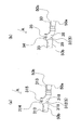
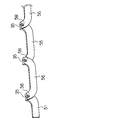
図12は、本発明にかかる実施の形態3におけるU相バスバー300Uの斜視構成図である。図12に示すように、本実施の形態3のU相バスバー300Uは、実施の形態1と同様に、一本の平角線50によって、ステータコア10の外周に沿うようにリング状に形成されており、端子31と、渡り部36、37と、コイル接続部302と、渡り部33とを備えている。
FIG. 12 is a perspective configuration diagram of a
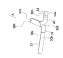
図13は、図12のT部拡大図である。図12及び図13に示すように、本実施の形態では、コイル接続部302は、実施の形態1のコイル接続部32と異なり、リング状の内側(ステータコア10の内側)に向かって突出するように形成され、その先端部304に切り欠き部305が形成されている。尚、本発明の円状のバスバーの一例は、本実施の形態のU相バスバー300に対応する。又、本発明の折り目の一例は、本実施の形態の先端部304に対応する。
FIG. 13 is an enlarged view of a T portion in FIG. As shown in FIGS. 12 and 13, in the present embodiment, unlike the
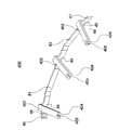
図14は、中性バスバー400の斜視構成図である。本実施の形態2の中性バスバー400は、実施の形態1と同様に、一本の平角線50によって形成されており、コイル接続部402と、コイル接続部402を連結する渡り部43とを備えている。コイル接続部402は、実施の形態1のコイル接続部42と異なっており、ステータコア10の内側に向かって突出するように形成されている。そして、コイル接続部402は、その突出した先端部404に切り欠き部405が形成されている。尚、本発明の円弧状のバスバーの一例は、本実施の形態の中性バスバー400に対応する。又、本発明の折り目の一例は、本実施の形態の先端部404に対応する。
FIG. 14 is a perspective configuration diagram of the
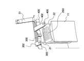
図15は、本実施の形態3のステータのU相コイル20U近傍の斜視構成図であり、U相コイル20Uの端21とU相バスバー300Uのコイル接続部302の間の連結及びU相コイル20Uの端22と中性バスバー400のコイル接続部402の間の連結状態を示す図である。
FIG. 15 is a perspective configuration diagram of the vicinity of the
図15に示すように、本実施の形態3では、コイル接続部302及びコイル接続部402が、ステータコア10の内周側に突出して形成され、コイル接続部302の切り欠き部305は、端21がU相コイル20Uから引き出されている部分の上方に配置されており、コイル接続部402の切り欠き部405は、端22がU相コイル20Uから引き出されている部分の上方に配置されている。そのため、実施の形態3では、端21及び端22をほぼ垂直に配置した状態で、それぞれをU相バスバー300Uの切り欠き部305及び中性バスバー400の切り欠き部405に挿入し、電気的に接続することが出来る。
As shown in FIG. 15, in the third embodiment, the
尚、本実施の形態3のバスバーを製造する際には、実施の形態1におけるクランク形状部518の長さ(図6(d)中、h参照)を長くし、フラットワイズに曲げることで、コイル接続部302の内側に突出する分の長さを確保することが出来る。
When manufacturing the bus bar of the third embodiment, the length of the
以上のように、本実施の形態3の構成では、実施の形態1のように、端21及び端22を、ステータコア10の外周側に向けて引き回す必要がないため、より簡単に製造を行うことが可能となる。
As described above, in the configuration of the third embodiment, the
(実施の形態4)
次に、本発明にかかる実施の形態4のバスバーについて説明する。本実施の形態4のバスバーは、実施の形態2と基本的な構成は同じであるが、実施の形態2とはコイル接続部の形状が異なっている、そのため、本相違点を中心に説明する。尚、実施の形態1と同様の構成については同一の符号が付されている。
(Embodiment 4)
Next, the bus bar according to the fourth embodiment of the present invention will be described. The basic configuration of the bus bar of the fourth embodiment is the same as that of the second embodiment, but the shape of the coil connection portion is different from that of the second embodiment. Therefore, this difference will be mainly described. . In addition, the same code | symbol is attached | subjected about the structure similar to
図16は、本発明にかかる実施の形態4におけるU相バスバー320Uの斜視構成図である。図16に示すように、本実施の形態4のU相バスバー320Uは、実施の形態2と同様に、一本の平角線50によって、ステータコア10の外周に沿うようにリング状に形成されており、端子31と、渡り部316、317と、コイル接続部322と、渡り部313を備えている。
FIG. 16 is a perspective configuration diagram of a
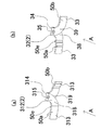
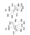
図17(a)は、端51から1番目のコイル接続部322(1)の斜視構成図であり、図17(b)は、端51から4番目のコイル接続部322(4)の斜視構成図である。図16及び図17(a)、(b)に示すように、本実施の形態のコイル接続部322は、実施の形態2のコイル接続部312と異なり、リング状の内側(ステータコア10の内側)に向かって突出するように形成され、その先端部324に切り欠き部325が形成されている。尚、本発明の円状のバスバーの一例は、本実施の形態のU相バスバー320に対応する。又、本発明の折り目の一例は、本実施の形態の先端部324に対応する。
17A is a perspective configuration diagram of the first coil connection portion 322 (1) from the
又、実施の形態2と同様に、図17(a)に示すように、コイル接続部322(1)では、中心側から視てコイル接続部322とその左側の渡り部316とが繋がっている部分318は、コイル接続部322とその右側の渡り部313とが繋がっている部分319よりも外周側に位置しており、この構成は、コイル接続部322(3)、(5)においても同様である。又、実施の形態2と同様に、図17(b)に示すように、コイル接続部322(4)では、中心側から視てコイル接続部322とその左側の渡り部313とが繋がっている部分318は、コイル接続部322とその右側の渡り部313とが繋がっている部分319よりも内周側に位置しており、この構成は、コイル接続部322(2)、(6)においても同様である。
Similarly to the second embodiment, as shown in FIG. 17A, in the coil connection portion 322 (1), the
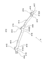
図18は、本発明にかかる実施の形態2における中性バスバー420の斜視構成図である。本実施の形態4の中性バスバー420は、実施の形態2と同様に、一本の平角線50によって形成されており、コイル接続部422と、コイル接続部422を連結する渡り部413とを備えている。コイル接続部422は、実施の形態2のコイル接続部412と異なっており、ステータコア10の内側に向かって突出するように形成されている。そして、コイル接続部422は、その突出した先端部424に切り欠き部425が形成されている。尚、本発明の円弧状のバスバーの一例は、本実施の形態の中性バスバー420に対応する。又、本発明の折り目の一例は、本実施の形態の先端部424に対応する。
FIG. 18 is a perspective configuration diagram of a
尚、本実施の形態4のバスバーを製造する際には、実施の形態2におけるクランク形状部57の長さ(図11(b)中、h参照)を長くすることで、内側に突出する分の長さを確保することが出来、重なった部分58の先端に切り欠き部35が形成された後、重なった部分58を内側にフラットワイズに曲げることにより、コイル接続部322が形成される。
When manufacturing the bus bar of the fourth embodiment, the length of the crank-shaped
又、コイル20とバスバーとの接続は、実施の形態3と同様のため省略する。 Further, since the connection between the coil 20 and the bus bar is the same as that of the third embodiment, the description thereof is omitted.
以上のように、本実施の形態4の構成では、実施の形態2のように、端21及び端22を、ステータコア10の外周側に向けて引き回す必要がないため、より簡単に製造を行うことが可能となる。
As described above, in the configuration of the fourth embodiment, it is not necessary to route the
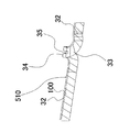
尚、上記実施の形態1〜4に記載のバスバーの平角線50としては、単線導体上に、ポリウレタン樹脂、ポリエステル樹脂等の絶縁被膜を施したエナメル線が用いられたものが用いられているが、エナメル導線に限らず、平角銅線にテープ状の絶縁フィルムを横巻きに巻き付けたものが用いられても良い。図19(a)は、絶縁フィルム100の断面構成図である。図19(a)に示すように、絶縁フィルム100は、絶縁材料として一般的に使われているポリイミドの層110の下側にテフロン(登録商標)の層120が形成されたものである。尚、平角銅線500に絶縁フィルム100を巻き付ける際には、テフロン層120が平角銅線500に接し、絶縁フィルム100は少なくとも一部が重なるようにして、図19(b)に示すように横巻きに巻き付けられる。尚、巻き付けの際に加熱することによって、テフロン層120が加熱されて溶け、平角銅線500に密着するため、接着剤を用いる必要がない。図20に、平角銅線500に絶縁フィルム100を巻き付けた平角線510を用いたU相バスバー30Uの部分斜視構成図を示す。尚、本発明の絶縁テープの一例は、図19(a)に示す絶縁フィルム100に対応する。
In addition, as the
又、上記実施の形態1〜4では、コイル20として、丸線を捲き回して形成されたものを用いて説明したが、平角線を用いて形成されたものが用いられてもよい。 Moreover, although the said Embodiment 1-4 demonstrated using the coil 20 formed by winding a round wire, what was formed using the flat wire may be used.
又、上記実施の形態1〜4では、3相のステータを用いたが、3相に限られるものではない。 Moreover, in the said Embodiment 1-4, although the three-phase stator was used, it is not restricted to three phases.
本発明のバスバーは、歩留まりの良好な又は占積率の良好な効果を有し、ステータ等として利用することが出来る。 The bus bar of the present invention has an effect of good yield or good space factor, and can be used as a stator or the like.
10 ステータコア
11 ティース
20U U相コイル
20V V相コイル
20W W相コイル
21、22 端
30U、300U、310U、320U U相バスバー
30V V相バスバー
30W W相バスバー
31 端子
32、302、312、322 コイル接続部
33、303、313 渡り部
34、304、314、324 先端部
35、305、315、325 切り欠き部
40、400、410、420 中性バスバー
42、402、412、422 コイル接続部
44、404、414、424 先端部
45、405、415、425 切り欠き部
43、413 渡り部
50 平角線
55、56、57、550、560、570、 線材部分
58、580 重なり部
DESCRIPTION OF
Claims (7)
前記平角線の一端から他端の間に形成された、前記コイルの一端と接続する複数のコイル接続部と、
隣り合う前記コイル接続部の間に形成された渡り部とを備え、
前記コイル接続部では、前記平角線の一部において、前記平角線の主面同士が重なっている、バスバー。 A bus bar that connects one end of a plurality of coils and is formed in a circular or arc shape with a single rectangular wire,
A plurality of coil connecting portions formed between one end of the flat wire and the other end, connected to one end of the coil;
A transition portion formed between adjacent coil connection portions,
In the coil connection portion, a bus bar in which main surfaces of the rectangular wires overlap each other in a part of the rectangular wires.
折り目の部分に、切り欠き部が形成されている、請求項1記載のバスバー。 The main surfaces of the flat wire are overlapped by bending the flat wire,
The bus bar according to claim 1, wherein a notch is formed in the fold portion.
前記円状又は前記円弧状の軸と平行な方向に形成されている、請求項1記載のバスバー。 The coil connection part is
The bus bar according to claim 1, wherein the bus bar is formed in a direction parallel to the circular or arcuate axis.
前記円状又は前記円弧状の内側に向かって形成されている、請求項1記載のバスバー。 The coil connection part is
The bus bar according to claim 1, wherein the bus bar is formed toward the inside of the circular shape or the circular arc shape.
前記ステータコアのティースに配置された複数のU相コイルと、
前記ステータコアのティースに配置された複数のV相コイルと、
前記ステータコアのティースに配置された複数のW相コイルと、
前記複数のU相コイルを接続するU相バスバーと、
前記複数のV相コイルを接続するV相バスバーと、
前記複数のW相コイルを接続するW相バスバーと、
前記複数のU相コイル、前記複数のV相コイル、及び複数のW相コイルを中性点に接続する中性バスバーとを備え、
前記U相バスバー、前記V相バスバー、前記W相バスバー、及び前記中性バスバーのうち少なくとも1つに請求項1記載のバスバーが用いられている、ステータ。 A stator core;
A plurality of U-phase coils arranged on the teeth of the stator core;
A plurality of V-phase coils disposed on the teeth of the stator core;
A plurality of W-phase coils disposed on the teeth of the stator core;
A U-phase bus bar connecting the plurality of U-phase coils;
A V-phase bus bar connecting the plurality of V-phase coils;
A W-phase bus bar connecting the plurality of W-phase coils;
A neutral bus bar that connects the plurality of U-phase coils, the plurality of V-phase coils, and the plurality of W-phase coils to a neutral point;
The stator in which the bus bar according to claim 1 is used for at least one of the U-phase bus bar, the V-phase bus bar, the W-phase bus bar, and the neutral bus bar.
Priority Applications (1)
| Application Number | Priority Date | Filing Date | Title |
|---|---|---|---|
| JP2011139758A JP5259778B2 (en) | 2011-06-23 | 2011-06-23 | Busbar and stator |
Applications Claiming Priority (1)
| Application Number | Priority Date | Filing Date | Title |
|---|---|---|---|
| JP2011139758A JP5259778B2 (en) | 2011-06-23 | 2011-06-23 | Busbar and stator |
Publications (2)
| Publication Number | Publication Date |
|---|---|
| JP2013009495A JP2013009495A (en) | 2013-01-10 |
| JP5259778B2 true JP5259778B2 (en) | 2013-08-07 |
Family
ID=47676359
Family Applications (1)
| Application Number | Title | Priority Date | Filing Date |
|---|---|---|---|
| JP2011139758A Active JP5259778B2 (en) | 2011-06-23 | 2011-06-23 | Busbar and stator |
Country Status (1)
| Country | Link |
|---|---|
| JP (1) | JP5259778B2 (en) |
Cited By (1)
| Publication number | Priority date | Publication date | Assignee | Title |
|---|---|---|---|---|
| EP4047792A4 (en) * | 2019-10-15 | 2022-12-14 | LG Innotek Co., Ltd. | ENGINE |
Families Citing this family (5)
| Publication number | Priority date | Publication date | Assignee | Title |
|---|---|---|---|---|
| JP5853598B2 (en) * | 2011-09-02 | 2016-02-09 | 株式会社明電舎 | Rotating electric machine |
| JP6204188B2 (en) * | 2013-12-27 | 2017-09-27 | トヨタ自動車株式会社 | Rotating electric machine stator |
| JP2016021467A (en) * | 2014-07-14 | 2016-02-04 | 達昭 浦谷 | Wiring structure for solar cell module and method for manufacturing wiring structure for solar cell module |
| JP6511869B2 (en) * | 2015-03-03 | 2019-05-15 | 日産自動車株式会社 | Coil wire bonding method of rotating electrical machine, method of manufacturing bus bar of rotating electrical machine, and bus bar of rotating electrical machine |
| JP2023122304A (en) * | 2022-02-22 | 2023-09-01 | 株式会社アイシン | Rotating electric machine stator |
Family Cites Families (6)
| Publication number | Priority date | Publication date | Assignee | Title |
|---|---|---|---|---|
| JPS56150938A (en) * | 1980-04-23 | 1981-11-21 | Mitsubishi Electric Corp | Interpole crossover track |
| JP3650372B2 (en) * | 2002-05-07 | 2005-05-18 | 三菱電機株式会社 | Rotating electric machine |
| JP5232547B2 (en) * | 2008-06-30 | 2013-07-10 | 日立オートモティブシステムズ株式会社 | Rotating electric machine |
| JP4636192B2 (en) * | 2009-03-23 | 2011-02-23 | ダイキン工業株式会社 | Bus ring and its mounting structure |
| JP5463711B2 (en) * | 2009-03-31 | 2014-04-09 | 日本電産株式会社 | Motor and method of manufacturing annular power supply member for motor |
| JP5729091B2 (en) * | 2010-10-29 | 2015-06-03 | 日本電産株式会社 | Bus bar, motor and manufacturing method thereof |
-
2011
- 2011-06-23 JP JP2011139758A patent/JP5259778B2/en active Active
Cited By (1)
| Publication number | Priority date | Publication date | Assignee | Title |
|---|---|---|---|---|
| EP4047792A4 (en) * | 2019-10-15 | 2022-12-14 | LG Innotek Co., Ltd. | ENGINE |
Also Published As
| Publication number | Publication date |
|---|---|
| JP2013009495A (en) | 2013-01-10 |
Similar Documents
| Publication | Publication Date | Title |
|---|---|---|
| US8674577B2 (en) | Stator for electric rotating machine | |
| JP5586969B2 (en) | Rotating electric machine stator | |
| CN101689777B (en) | Stator for rotary electric machine and rotary electric machine using same | |
| US8779643B2 (en) | Stator for electric rotating machine and method of manufacturing same | |
| CN101958589B (en) | Stators for rotating electrical machines | |
| US8082653B2 (en) | Method of producing coil made up of rectangular wave-shaped windings | |
| JP5070248B2 (en) | Rotating electric machine and manufacturing method thereof | |
| JP6033582B2 (en) | Stator and stator manufacturing method | |
| JP5989496B2 (en) | Bus ring for stator of rotating electrical machine | |
| JP5259778B2 (en) | Busbar and stator | |
| JP5304058B2 (en) | Concentrated winding stator manufacturing method and concentrated winding stator | |
| JP6638629B2 (en) | Rotating electric machine stator | |
| JP2011151953A (en) | Stator of dynamo-electric machine | |
| JP2011072052A (en) | Stator and method for manufacturing the same | |
| WO2014007177A1 (en) | Stator | |
| CN103840589A (en) | Hairpin bar and hairpin winding motor having same | |
| JP6288002B2 (en) | Manufacturing method of rotating electrical machine stator and cassette coil for rotating electrical machine | |
| US8659201B2 (en) | Stator for electric rotating machine | |
| KR20230034943A (en) | Stators and electric machines for electric machines | |
| CN110476325B (en) | Rotating electrical machine | |
| JP6443303B2 (en) | Rotating electrical machine stator | |
| JP5434227B2 (en) | Stator and stator manufacturing method | |
| JP2022182851A (en) | stator | |
| JP5972154B2 (en) | Rotating electric machine | |
| JP2015119535A (en) | Rotary electric machine stator |
Legal Events
| Date | Code | Title | Description |
|---|---|---|---|
| TRDD | Decision of grant or rejection written | ||
| A01 | Written decision to grant a patent or to grant a registration (utility model) |
Free format text: JAPANESE INTERMEDIATE CODE: A01 Effective date: 20130423 |
|
| A61 | First payment of annual fees (during grant procedure) |
Free format text: JAPANESE INTERMEDIATE CODE: A61 Effective date: 20130424 |
|
| FPAY | Renewal fee payment (event date is renewal date of database) |
Free format text: PAYMENT UNTIL: 20160502 Year of fee payment: 3 |
|
| R150 | Certificate of patent or registration of utility model |
Ref document number: 5259778 Country of ref document: JP Free format text: JAPANESE INTERMEDIATE CODE: R150 Free format text: JAPANESE INTERMEDIATE CODE: R150 |
|
| R250 | Receipt of annual fees |
Free format text: JAPANESE INTERMEDIATE CODE: R250 |
|
| R250 | Receipt of annual fees |
Free format text: JAPANESE INTERMEDIATE CODE: R250 |
|
| R250 | Receipt of annual fees |
Free format text: JAPANESE INTERMEDIATE CODE: R250 |
|
| R250 | Receipt of annual fees |
Free format text: JAPANESE INTERMEDIATE CODE: R250 |
|
| R250 | Receipt of annual fees |
Free format text: JAPANESE INTERMEDIATE CODE: R250 |
|
| R250 | Receipt of annual fees |
Free format text: JAPANESE INTERMEDIATE CODE: R250 |
|
| R250 | Receipt of annual fees |
Free format text: JAPANESE INTERMEDIATE CODE: R250 |
|
| R250 | Receipt of annual fees |
Free format text: JAPANESE INTERMEDIATE CODE: R250 |
|
| R250 | Receipt of annual fees |
Free format text: JAPANESE INTERMEDIATE CODE: R250 |
|
| R250 | Receipt of annual fees |
Free format text: JAPANESE INTERMEDIATE CODE: R250 |
|
| R250 | Receipt of annual fees |
Free format text: JAPANESE INTERMEDIATE CODE: R250 |