EP3079233A1 - Electric power collection/distribution ring and electric motor - Google Patents

Electric power collection/distribution ring and electric motor Download PDF

Info

Publication number
EP3079233A1
EP3079233A1 EP13898795.3A EP13898795A EP3079233A1 EP 3079233 A1 EP3079233 A1 EP 3079233A1 EP 13898795 A EP13898795 A EP 13898795A EP 3079233 A1 EP3079233 A1 EP 3079233A1
Authority
EP
European Patent Office
Prior art keywords
bus
ring
rotational axis
axis line
bus ring
Prior art date
Legal status (The legal status is an assumption and is not a legal conclusion. Google has not performed a legal analysis and makes no representation as to the accuracy of the status listed.)
Withdrawn
Application number
EP13898795.3A
Other languages
German (de)
French (fr)
Other versions
EP3079233A4 (en
Inventor
Kenichi Egami
Current Assignee (The listed assignees may be inaccurate. Google has not performed a legal analysis and makes no representation or warranty as to the accuracy of the list.)
Proterial Ltd
Original Assignee
Hitachi Metals Ltd
Priority date (The priority date is an assumption and is not a legal conclusion. Google has not performed a legal analysis and makes no representation as to the accuracy of the date listed.)
Filing date
Publication date
Application filed by Hitachi Metals Ltd filed Critical Hitachi Metals Ltd
Publication of EP3079233A1 publication Critical patent/EP3079233A1/en
Publication of EP3079233A4 publication Critical patent/EP3079233A4/en
Withdrawn legal-status Critical Current

Links

Images

Classifications

    • HELECTRICITY
    • H02GENERATION; CONVERSION OR DISTRIBUTION OF ELECTRIC POWER
    • H02KDYNAMO-ELECTRIC MACHINES
    • H02K3/00Details of windings
    • H02K3/46Fastening of windings on the stator or rotor structure
    • H02K3/50Fastening of winding heads, equalising connectors, or connections thereto
    • HELECTRICITY
    • H02GENERATION; CONVERSION OR DISTRIBUTION OF ELECTRIC POWER
    • H02KDYNAMO-ELECTRIC MACHINES
    • H02K2203/00Specific aspects not provided for in the other groups of this subclass relating to the windings
    • H02K2203/09Machines characterised by wiring elements other than wires, e.g. bus rings, for connecting the winding terminations

Definitions

  • This invention relates to an electric power collection/distribution ring to perform electrical collection and distribution for windings coiled around an iron core of a stator, and an electric motor with the electric power collection/distribution ring.
  • an electric power collection/distribution ring for an electric motor which comprises a plurality of conductive members to be connected respectively with windings coiled around an iron core of a stator, has been known (See, e.g., PTL 1 ).
  • the electric power collection/distribution ring described in PTL 1 includes a connection terminal comprising first, second, third and fourth conductive members and an annular holding member (connection substrate) holding these conductive members.
  • the first, second, third and fourth conductive members are fitted in holding grooves formed at a holding member such that the first to fourth conductive members are aligned in two lines in an axial direction and in two lines in a radial direction, respectively.
  • the first and second conductive members are disposed inwardly in the radial direction than the third and fourth conductive members.
  • connection portions to be connected to ends of the winding for each phase of the stator are formed by bending the conductive member such that the connection portion protrudes from the holding groove in the axial direction.
  • the ends of a winding drawn inwardly in the radial direction of the holding member are connected to the connection portions of the first and second conductive members, and the ends of a winding drawn outwardly in the radial direction of the holding member are connected to the connection portions of the third and fourth conductive members.
  • Respective connection portions of the first to the fourth conductive members and the ends of respective windings are joined with each other e.g. by welding.
  • the winding to be connected to the connection portions of the first and second conductive members is drawn inwardly in the radial direction of the holding member, and the winding to be connected to the connection portions of the third and fourth conductive members is drawn outwardly in the radial direction of the holding member.
  • each winding might not be drawn in such a manner, and in that case, for example, it is necessary to route the ends of the winding outside the stator along the radial direction of the stator. As a result, wiring work might become complicated.
  • an embodiment of the invention provides an electric power collection/distribution ring, to be arranged in parallel with a stator in a direction of a rotational axis line of a rotor of a three-phase alternating current electric motor, comprising:
  • an electric motor comprising:
  • the electric power collection/distribution ring and the electric motor of the present invention it is possible to achieve easier connection between a winding and a connection terminal to be connected to the winding as well as contribution to downsizing.
  • a three-phase alternating current electric motor in the embodiment according to the present invention is used as, for example, a vehicle driving source for running and is supported by a vehicle body.
  • FIG.1 is a perspective view showing a configuration example of an electric motor 1 in the embodiment according to the present invention. Besides, a rotational axis line O of a rotor 22 and an output shaft 23 is shown in FIG.1 by chain line.
  • the electric motor 1 comprises a cylindrical stator 21, the rotor 22 rotatable with respect to the stator 21 which is arranged at an inner side than the stator 21 in a radial direction of the stator 21, the output shaft 23 penetrating a central portion of the rotor 22, which is integrated with the rotor 22 and rotatably supported, and an electric power collection/distribution ring 11 arranged in parallel with the stator 21 in a direction of the rotational axis line O of the rotor 22.
  • the stator 21, the rotor 22, and the output shaft 23 are arranged concentrically about the rotational axis line O, and the output shaft 23, the rotor 22 and the stator 21 are arranged in this order from an innermost side to an outermost side.
  • the electric power collection/distribution ring 11 is arranged concentrically about the rotational axis line O, and comprising first to fourth bus rings 31 to 34, first, second and third power supply terminals 41 to 43 which are connected to the first to fourth bus rings 31 to 34 respectively, and connected to a terminal base 20 formed at an outer side than the first to fourth bus rings 31 to 34 in a direction orthogonal to the rotational axis line O by a bolt 20 a, a plurality of first to fourth connection terminals 51 to 54 for connecting between respective phase windings 210 (U-phase winding 211, V-phase winding 212, W-phase winding 213 ) of the stator 21 and the first to fourth bus rings 31 to 34, and a plurality of (in the present embodiment, six) holding members 30 which hold the first to fourth bus rings 31 to 34.
  • the terminal base 20 is connected to a wire harness (not shown) of which one end is connected to an inverter, and the other end of the wire harness are electrically connected to the first, second and third power supply terminals 41 to 43 via the terminal base 20. Electric current output from the inverter is fed to the electric motor 1 through the wire harness and the first, second and third power supply terminals 41 to 43.
  • the terminal base 20 is fixed on a fixed section in a body of a vehicle (not shown).
  • the first to fourth bus rings 31 to 34 are arranged closer to the stator 21 than the terminal base 20 in the direction of the rotational axis line O.
  • the plurality of (in the present embodiment, four) first connection terminals 51 are provided at the first bus ring 31, the plurality of (in the present embodiment, four) second connection terminals 52 are provided at the second bus ring 32, the plurality of (in the present embodiment, four) third connection terminals 53 are provided on the third bus ring 33, and the plurality of (in the present embodiment, twelve) fourth connection terminals 54 are provided at the fourth bus ring 34 respectively.
  • the plurality of first connection terminals 51 are connected to one end of the U-phase winding 211
  • the plurality of second connection terminals 52 are connected to one end of the V-phase winding 212
  • the plurality of third connection terminals 53 are connected to one end of the W-phase winding 213 respectively by e.g. fusing.
  • the plurality of fourth connection terminals 54 are connected to the other ends of the U-phase winding 211, the V-phase winding 212, and the W-phase winding 213 respectively.
  • a circuit of current flow through the U-phase winding 211, the V-phase winding 212, and the W-phase winding 213 is closed by the fourth bus ring 34 (closed circuit).
  • the fourth bus ring 34 is a neutral-phase bus ring for forming the closed circuit in the U-phase winding 211, V-phase winding 212, and W-phase winding 213.
  • FIG.2 is a perspective view showing a configuration example of the electric power collection/distribution ring 11 in the embodiment according to the present invention.
  • FIG.3 is a sectional view of the electric power collection/distribution ring 11 taken along A-A line in FIG.2 .
  • FIG.4 is a schematic diagram showing a positional relationship between connection portions 312, 322, 332 of first to fourth bus rings 31 to 33 with respect to ring portions 311, 321, 331.
  • the rotational axis line O is shown in FIG.4 by chain line.
  • the first to third bus rings 31 to 33 are configured by bending insulated electric wires respectively comprising core conductors 310 a, 320 a, 330 a, insulators 310 b, 320 b, 330 b covering the core conductors 310 a, 320 a, 330 a, and comprising ling portions 311, 321, 331 which are formed annularly about the rotational axis line O, and connection terminals 312, 322, 332 to connect between the ring portions 311, 321, 331 and the first, second and third power supply terminals 41 to 43.
  • the fourth bus ring 34 is configured by bending an insulated electric wire comprising a core conductor 340 a and an insulator 340 b, and formed annularly about the rotational axis line O without any connection portion to connect with the first, second, and third power supply terminals 41 to 43.
  • the fourth bus ring 34 is, as described above, the neutral-phase bus ring to provide the closed circuit in the U-phase winding 211, V-phase winding 212, and W-phase winding 213, the connection terminal is not connected to any end of the fourth bus ring 34, unlike configurations of the first to third bus rings 31 to 33. Therefore, the fourth bus ring 34 is consisting of a ring portion 341.
  • the term "ring” refers to a shape extending substantially along by around circumferential direction of the stator 21.
  • the bus ring may be formed in a polygonal shape or a plurality of circular-arc shaped conductive members may be combined to provide a single bus ring, if whole of the bus ring extends substantially along by around a circumferential direction of the stator 21, such a shape is included in "ring".
  • the first to fourth bus rings 31 to 34 are arranged such that the first bus ring 31 and the fourth bus ring 34 are arranged in parallel (juxtaposed) in the direction of the rotational axis line O, and that the second bus ring 32 and the third bus ring 33 are arranged in parallel in the direction of the rotational axis line O. Moreover the first bus ring 31 and the second bus ring 32 are arranged in parallel in the direction orthogonal to the rotational axis line O, and the third bus ring 33 and the fourth bus ring 34 are arranged in parallel in the direction orthogonal to the rotational axis line O.
  • the fourth bus ring 34 is arranged between the first bus ring 31 and the stator 21 (cf. FIG.4 ) in the direction of the rotational axis line O
  • the third bus ring 33 is arranged between the second bus ring 32 and the stator 21 in the direction of the rotational axis line O.
  • the third bus ring 33 and the fourth bus ring 34 are arranged closer to the stator 21 than the first bus ring 31 and the second bus ring 32 in the direction of the rotational axis line O.
  • the first bus ring 31 and the fourth bus ring 34 are arranged closer to the rotational axis line O than the second bus ring 32 and the third bus ring 33.
  • first to fourth bus rings 31 to 34 are arranged such that the first bus ring 31 overlaps at least partially the fourth bus ring 34 in a view from the direction of the rotational axis line O, and the second bus ring 32 overlaps at least partially the third bus ring 33 in the view from the direction of the rotational axis line O, the first bus ring 31 overlaps at least partially the second bus ring 32 in a view from the direction orthogonal to the rotational axis line O, and the third bus ring 33 overlaps at least partially the fourth bus ring 34 in the view from the direction orthogonal to the rotational axis line O.
  • a distance between the first bus ring 31 and the second bus ring 32, and a distance between the third bus ring 33 and the fourth bus ring 34 are respectively set to be shorter than diameters of the insulated electric wires constituting the first to fourth bus rings 31 to 34 respectively.
  • a distance between the first bus ring 31 and the neutral-phase ring 34 and a distance between the second bus ring 32 and the third bus ring 33 are respectively arranged to be spaced apart so as not to interfere with each other due to e.g. vibration of a vehicle.
  • a ring portion 311 in the first bus ring 31 is connected to the plurality of first connection terminals 51
  • a ring portion 321 in the second bus ring 32 is connected to the plurality of second connection terminals 52
  • a ring portion 331 in the third bus ring 33 is connected to the plurality of third connection terminals 53
  • a ring portion 341 in the fourth bus ring 34 is connected to the plurality of fourth connection terminals 54, at even intervals in the circumferential direction respectively.
  • the first to fourth connection terminals 51 to 54 and the fourth connection terminal 54 are arranged such that the first connection terminal 51, the fourth connection terminal 54, the second connection terminal 52, the fourth connection terminal 54, the third connection terminal 53, the fourth connection terminal 54, the first connection terminal 51, ...in a clockwise direction along with a circumferential direction of the first to fourth bus rings 31 to 34.
  • the first connection portion 312 of the first bus ring 31 and the second connection portion 322 of the second bus ring 32 comprise base end sections 312 a, 322 a and extending portions 312 b, 322 b extended from the base end sections 312 a, 322 a for the terminal base 20 in the direction of the rotational axis line O, integrally.
  • the base end sections 312 a, 322 a are bent in a circular-arc shape respectively in the space between both ends of the ring portions 311, 312 and the extending portions 312 b, 322 b.
  • a connection portion 332 of the third bus ring 33 comprises a base end section 332 a and an extending portion 332 b integrally likewise the first and second bus rings 31, 32.
  • a shape of the base end section 332 a is different from the base end sections 312 a, 322 a of the first and second bus rings 31, 32.
  • the shape of the base end section 332a of the third bus ring 33 will be described later.
  • the first to third power supply terminals 41 to 43 comprise connecting chips 411, 421, 431 each having a planar shape, and swaging sections 412, 422, 432 integrally which swage the core conductors 310 a, 320 a, 330 a exposed from the insulators 310 b, 320 b, 330 b in tips of the extending portions 312 b, 322 b, 332 b of the first, second and third bus rings 31, 32, 33.
  • the connecting chips 411, 421, 431 are formed by partially bending ends of the swaging section 412, 422, 433 so as to project outwardly in the radial direction of the first to fourth bus rings 31 to 34.
  • the connecting chips 411, 421, 431 are pierced through through-holes 411 a, 421 a , 431 a in the direction parallel with the direction of the rotational axis line O to accommodate the bolt 20 a (cf. FIG.1 ) to connect between the first to third power supply terminal 41 to 43 and the terminal base 20.
  • Base end sections 312 a, 322 a of the connection terminals 312, 322 are is configured to extend from both ends of the ring portions 311, 321 toward an opposite side of the stator 21 in a direction in parallel with the rotational axis line O respectively with describing a circular-arc.
  • extending portions 312 b, 322 b are configured to further extend from an end of the end of the bases 312 a, 322 b toward the opposite side of the stator 21 in the direction parallel with the rotational axis line O.
  • connection terminals 312, 322 of the first and second bus rings 31, 32 are configured such that the base end sections 312 a, 322 a and the extending portion 312 b, 322 b are extending in the direction parallel with the rotational axis line O.
  • a base end section 332 a of the base 332 is configured to extend outwardly in the radial direction of the third bus ring 33 from both ends of the ring portion 331, and toward an opposite side of the stator 21 in the direction parallel with the rotational axis line O.
  • an extending portion 332 b is configured to further extend toward the opposite side of the stator 21 in the direction parallel with the rotational axis line O from an end of the end of the base 332 a. Therefore, the connection portion 332 is located at an outer side than the ring portion 331 in the radial direction in a view from the rotational axis line O.
  • FIG.5 A is a perspective view showing a configuration example of a holding member 30.
  • FIG.5 B is a side view of the holding member 30 in FIG.5 A viewed from an arrow B.
  • the holding member 30 is made from an insulating member, e.g., resin etc., and comprises an inner wall section 305 arranged at an inner side than the first to fourth bus rings 31 to 34 in the radial direction, an outer wall section 306 arranged at an outer side than the first to fourth bus rings 31 to 34 in the radial direction, a central wall section 307 interposed between the inner wall section 305 and the outer wall section 306 as one piece.
  • the inner wall section 305, the outer wall section 306, and the central wall section 307 are shaped in a gradual arc along a shape of the first to fourth bus rings 31 to 34.
  • a first holding groove 301 to hold the first bus ring 31 and a fourth holding groove 304 to hold the fourth bus ring 34 are formed between the inner wall section 305 and the central wall section 307, and a second holding groove 302 to hold the second bus ring 32 and a third holding groove 303 to hold the third bus ring 33 are formed between the outer wall section 306 and the central wall section 307.
  • the holding member 30 comprises a partition section 308 a to separate between the first holding groove 301 and the fourth holding groove 304 in a portion between the inner wall section 305 and the central section 307, and a partition section 308b to separate between the second holding groove 302 and the third holding groove 303 in a portion between the outer wall section 306 and the central section 307.
  • a pair of salient portions 301 a, 301 b are formed on an inner surface of the first holding groove 301 to prevent the first bus ring 31 from being left out from the first holding groove 301.
  • a pair of salient portions 302 a 302 b are formed on an inner surface of the second holing groove 302
  • a pair of salient portions 303 a 303 b are formed on an inner surface of the third holing groove 303
  • a pair of salient portions 304 a 304 b are formed on an inner surface of the fourth holing groove 304.
  • one salient portion 301 a of the pair of salient portions 301 a, 301 b on the first holding groove 301 and one salient portion 304 a of the pair of salient portions 304 a , 304 b on the fourth holding groove 304 are formed on the side of the inner wall section 305, while the other salient portion 301 b in the first holding groove 301 and the other salient portion 304 b in the fourth holding groove 304 are formed respectively on the side of the central wall section 307.
  • One salient portion 302 a of the pair of salient portions 302 a, 302 b on the second holding groove 302 and one salient portion 303 a on the third holding groove 303 are formed on the side of the outer wall section 306 , while the other salient portion 302 b on the second holding groove 302 and the other salient portion 303 b on the third holding groove 303 are formed on the side of the central wall section 307.
  • FIG.6 is a perspective view of a first connection terminal 51 and its peripheral part.
  • FIG.7 is a perspective view of a fourth connection terminal 54 and its peripheral part.
  • FIG.8 is a perspective view of a second connection terminal 52 and its peripheral part.
  • FIG.9 is a perspective view of a third connection terminal 53 and its peripheral part.
  • the first and second bus rings 31, 32 are shown by the two-dot chain line in FIG.7 and FIG.9 .
  • the first connection terminal 51 integrally comprises, as shown in FIG.6 , a swaging section 511 swaged at a portion where the core conductor 310 a of the first bus ring 31 is exposed, a base 512 arranged on a side of one end in a circumferential direction of the first bus ring 31 in the swaging section 511, an extending portion 513 extending in a radial direction of the first to fourth bus rings 31 to 33 and the fourth bus ring 34 from a side of one end of the base 512, and a winding connection portion 514 which is formed at an opposite side of the other end of the base 512 in the extending portion 513, connected to one end of the U-phase winding 211 (cf. FIG.1 ).
  • the swaging section 511 swages the first bus ring 31 toward the direction of the rotational axis line O from an inside of the radial direction of the first bus ring 31.
  • the base 512 is formed in a rectangular shape in which long sides are formed in the direction of the rotational axis line O and short sides are formed in the circumferential direction of the first to fourth bus rings 31 to 34.
  • the extending portion 513 extends from an end of a side of the stator 21 in a direction of the long sides of the base 512 outwardly in the radial direction of the second bus ring 32. Namely, the extending portion 513 of the first connection terminal 51 connected to the first bus ring 31 is extending across an adjacent bus ring (the second bus ring 32 ) in the radial direction between the swaging section 511 and the winding connection portion 514.
  • both ends of the extending portion 513 (an end on the side of the base 512 and an end on the side of the winding connection portion 514 ) in an extending direction are bent toward an opposite side of the stator 21 in the direction of the rotational axis line O (on a side of the terminal base 20 ). Accordingly, the extending portion 513 is located closer to the stator 21 than the swaging section 511 and the winding connection portion 514.
  • the extending portion 513 is extending across in the direction orthogonal to the rotational axis line O between the first bus ring 31 and the fourth bus ring 34, as well as between the second bus ring 32 and the third bus ring 33 without contacting circumferential surfaces of the first to third bus rings 31 to 33 and the neutral-phase bus ring 34. Besides, it is enough for the extending portion 513 to intervene at least in a space between the second bus ring 32 and the third bus ring 33.
  • the winding connection portion 514 comprises a pair of straight portions 514 a extending toward the radial direction of the first to fourth bus rings 31 to 34, and a circular-arc portion 514 b having a circular-arc shape and linking the pair of straight portions 514 a as one piece.
  • the circular-arc portion 514 b is located on a side of the swaging section 511 in the radial direction of the first to fourth bus rings 31 to 34. Accordingly, the winding connection portion 514 is configured to open outwardly in the radial direction of the second bus ring 32 and third bus rings 33.
  • the fourth connection terminal 54 comprises, as shown in FIG.7 , a swaging section 541 swaged at a portion where the core conductor 340 a of the fourth bus ring 34 are exposed, a base 542 arranged on a side of one end in the circumferential direction of the swaging section 541 of the fourth bus ring 34, an extending portion 543 extended over the second bus ring 32 and the third bus ring 33 in the direction orthogonal to the rotational axis line O from a side of one end of the base 542, and a winding connection portion 544 which is provided at an opposite side of the base 542 in the extending portion 543, connected to each of the other ends of the U-phase winding 211, V-phase winding 212, and W-phase winding 213 (cf. FIG.1 ) as one piece.
  • the swaging section 541 swages the fourth bus ring 34 in the direction of the rotational axis line O from an inside of the axial direction of the fourth bus ring 34.
  • the base 542 is formed in a rectangular shape in which long sides are formed in the direction of the rotational axis line O and short sides are formed in the circumferential direction of the first to fourth bus rings 31 to 34.
  • the extending portion 543 extends from an end on an opposite side of the stator 21 in a direction of the long side of the base 542 outwardly in the radial direction of the third bus ring 33.
  • the extending portion 543 of the fourth connection terminal 54 which is connected to the fourth bus ring 34 is extended over an adjacent bus ring (the third bus ring 33 ) in the radial direction between the swaging section 541 and the winding connection portion 544.
  • both ends in an extending direction of the extending portion 543 are bent toward a side of the stator 21 in the direction of the rotational axis line O. Accordingly, the swaging section 541 and the winding connection portion 544 are located closer to the stator 21 than the extending portion 543 in the direction of the rotational axis line O.
  • the extending portion 543 likewise the extending portion 513 of the first connection terminal 51, is extending across in the direction orthogonal to the rotational axis line O between the first bus ring 31 and the fourth bus ring 34, and between the second bus ring 32 and the third bus ring 33, without contacting the circumferential surfaces of the first to third bus rings 31 to 33 and the neutral-phase bus ring 34.
  • the first connection terminal 51 it is enough for the extending portion 543 of the fourth connection terminal 54 to intervene at least in a space between the second bus ring 32 and the third bus ring 33.
  • the winding connection portion 544 integrally comprises, likewise the winding connection portion 514 of the first connection terminal 51, a pair of straight portions 544 a and a circular-arc portion 514 b so as to open outwardly in the radial direction of the second bus ring 32 and the third bus rings 33.
  • the first connection terminal 51 and the fourth connection terminal 54 have an identical shape, but differ from each other in an orientation of a position.
  • the first connection terminal 51 and the fourth connection terminal 54 are composed of same shapes in all of the swaging portions 511, 541, the bases 512, 542, the extending portions 513, 543, and the winding connection portions 514,544.
  • the first connection terminal 51 is swaged to the first bus ring 31 so as to locate the extending portion 513 at the side of the stator 21 with respect to the swaging section 511 and the winding connection portion 514 in the direction of the rotational axis line O.
  • the fourth connection terminal 54 is swaged to the fourth bus ring 34 so as to locate the extending portion 543 at an opposite side of the stator 21 with respect to the swaging section 511 and the winding connection portion 514 in the direction of the rotational axis line O.
  • the second connection terminal 52 integrally comprises, as shown in FIG.8 , a swaging section 521 swaged at a portion where the core conductor 320 a of the second bus ring 32 is exposed, a base 522 which is provided at an a side of one end of the swaging section 521 in the circumferential direction of the second bus ring 32, and a winding connection portion 523 which is formed at one end on the side of the stator 21 in the direction of the rotational axis line O in the base 522, connected to one end of the V-phase winding 212 (cf. FIG.1 ).
  • the swaging section 521 swages the second bus ring 32 toward the direction of the rotational axis line O from an outside of the radial direction of the second bus ring 34.
  • the base 522 is formed in a rectangular shape in which long sides are formed in the direction of the rotational axis line O and short sides are formed in a circumferential direction of the first to fourth bus rings 31 to 33 and the fourth bus ring 34.
  • the winding connection portion 523 integrally comprises, likewise the winding connection portion 514 of the first connection terminal 51 and the winding connection portion 544 of the fourth connection terminal 54, a pair of straight portions 523 a and a circular-arc portion 523 b so as to open outwardly in the radial direction of the second bus ring 32 and the third bus ring 33.
  • the third connection terminal 53 integrally comprises, as shown in FIG.9 , a swaging section 531 swaged at a portion where the core conductor 330 a of the third bus ring 33 is exposed, a base 532 which is provided on a side of one end of the swaging section 531 in the circumferential direction of the third bus ring 33, and a winding connection portion 533 which is formed at one end of an opposite side of the stator 21 in the direction of the rotational axis line O in the base 532, connected to one end of the W-phase winding 213 (cf. FIG.1 ).
  • the swaging section 531 swages the third bus ring 33 in the direction of the rotational axis line O from an outside of the radial direction of the third bus ring 33.
  • the base 53 comprises long sides in the direction of the rotational axis line O and short sides in the circumferential direction of the first to fourth bus rings 31 to 34.
  • the winding connection portion 533 integrally comprises, likewise the winding connection portion 523 of the second connection terminal 52, a pair of straight portions 533 a and a circular-arc portion 533 b so as to open outwardly in the radial direction of the second bus ring 32 and the third bus ring 33.
  • the second connection terminal 52 and the third connection terminal 53 do not include any extending portion in contrast to the configuration of the first connection terminal 51 and the fourth connection terminal 54.
  • the second connection terminal 52 and the third connection terminal 53 have an identical shape, but differ from each other in an orientation of a position. That is to say, the second connection terminal 52 and the third connection terminal 53 are composed of same shapes in all of the swaging sections 521, 531, the bases 522, 532, and the winding connection portions 523, 533.
  • the second connection terminal 52 is swaged to the second bus ring 32 so as to locate the winding connection portion 523 on a side of the stator 21 with respect to the swaging section 521 in the direction of the rotational axis line O.
  • the third connection terminal 53 is swaged to the third-phase bus ring 33 so as to locate the winding connection portion 533 on an opposite side of the stator 21 with respect to the swaging section 531 in the direction of the rotational axis line O.
  • FIG.10 A is an explanatory diagram for explaining the positional relationship of the extending portion 513 of the first connection terminal 51 and the extending portion 543 of the fourth connection terminal 54 in the radial direction of the second bus ring 32 an the third bus ring 33.
  • the extending portion 513 of the first connection terminal 51 and the extending portion 543 of the fourth connection terminal 54 are configured such that a dimension d 1 in the direction parallel with the rotational axis line O (an alignment direction of the second bus ring 32 and the third bus ring 33 ) is shorter than a dimension d 2 in the direction along the circumferential direction of the first to fourth bus rings 31 to 34 (d 1 ⁇ d 2 ).
  • the second bus ring 32 and the extending portions 513, 543 are spaced apart from each other with a distance h so as not to interfere with each other due to e.g. vibration of a vehicle.
  • the third bus ring 33 and the extending portions 513, 543 are spaced apart from each other with the distance h so as not to interfere with each other due to e.g. vibration of a vehicle.
  • the distance h is around 1 to 5 mm.
  • a dimension in the rotational axis line O is a total of an addition of a diameter (outer diameter) of the insulated electric wire for the second bus ring 32 and a diameter (outer diameter) of the insulated electric wire for the third bus ring 33 and a dimension of ( 2 h+d 1 ).
  • FIG.10 B is an explanatory diagram showing a comparative example 1 as compared with FIG.10 A.
  • FIG.10 C is an explanatory diagram showing a comparative example 2 as compared with FIG.10 A .
  • the second bus ring 32 is closer to the stator 21 than the extending portion 513 of the first connection terminal 51
  • the fourth connection terminal 54 is closer to the stator 21 than the third bus ring 33.
  • the extending portion 513 of the first connection terminal 51 and the extending portion 543 of the fourth connection terminal 54 are not interposed between the second bus ring 32 and the third bus ring 33.
  • a dimension in the rotational axis line O is a total of an addition of a diameter (outer diameter) of the insulated electric wire for the second bus ring 32 and a diameter (outer diameter) of the insulated electric wire for the third bus ring 33 and a dimension of ( 3 h+ 2 d 1 ).
  • the extending portion 513 of the first connection terminal 51 and the extending portion 543 of the fourth connection terminal 54 are arranged such that, in a cross section parallel with the rotational axis line O between the second bus ring 32 and the third bus ring 33, a dimension d 1 in the alignment direction of the second bus ring 32 and the third bus ring 33 is set to be d 2 .
  • a dimension in the rotational axis line O is a total of an addition of a diameter (outer diameter) of the insulated electric wire for the second bus ring 32 and a diameter (outer diameter) of the insulated electric wire for the third bus ring 33 and a dimension of ( 2 h+d 2 ).
  • the embodiment as described above has the following functions and advantageous effects.
  • the first connection terminal 51 connected to the first bus ring 31 and the fourth connection terminal 54 connected to the fourth bus ring 34 respectively have the extending portions 513, 543 that are extending across the second bus ring 32 and the third bus ring 33 in the direction orthogonal to the rotational axis line O, so that it is possible to facilitate the connection with the windings 210 drawn outside from the electric power collection/distribution ring 11 in the rotational axis line O.
  • the extending portions 513, 543 are extending across in the direction orthogonal to the rotational axis line O a space between the second bus ring 32 and the third bus ring 33 that are securely spaced apart from each other with a predetermined distance, so that it is possible to reduce the thickness of the electric power collection/distribution ring 11 in the rotational axis line O as compared to the comparative example 1 as shown in FIG.10 B .
  • the extending portion 513 of the first connection terminal 51 and the extending portion 543 of the fourth connection terminal 54 are configured such that, in a cross section parallel with the rotational axis line O between the second bus ring 32 and the third bus ring 33, the dimension d 1 in the direction parallel with the rotational axis line O is shorter than the dimension d 2 in the direction along the circumferential direction of the first to fourth bus rings 31 to 34. Therefore, it is possible to reduce the thickness of the electric power collection/distribution ring 11 in the rotational axis line O as compared to the comparative example 2 as shown in FIG.10 C .
  • the various kinds of modifications can be implemented without departing from the gist of the invention.
  • the winding 210 is drawn to be located at an outer side than the electric power collection/distribution ring 11 in the direction orthogonal to the rotational axis line O
  • the invention is not to be limited to described above, e.g., it is possible to draw the winding 210 to be located at an inner side than the electric power collection/distribution ring 11 in the direction orthogonal to the rotational axis line O.
  • the first to fourth bus rings 31 to 34 are held by the plurality of holding members 30.
  • the present invention is not limited thereto, and the first to fourth bus rings 31 to 34 may be held by covering with e.g. a mold resin.
  • the extending portions 312 b, 322 b, 332 b of the connection terminals 312, 322, 332 of the first to third bus rings 31 to 33 are extended toward the terminal base 20 which is arranged at the opposite side of the stator 21 in the direction of the rotational axis line O.
  • the present invention is not limited to the embodiment as described above, and e.g. the extending portions 312 b, 322 b, 332 b may be extended toward a terminal base which is arranged at the side of the stator 21 in the direction of the rotational axis line O.
  • the connecting chips 411, 421, 431 in the first to third power supply terminals 41 to 43 are bent to be extended outwardly in the radial direction of the first to fourth bus rings 31 to 34.
  • the present invention is not limited to the first embodiment as described above, e.g., the connecting chips 411, 421, 431 may be extended in parallel with the rotational axis line O without bending.
  • the first to fourth connection terminals 51 to 54 are formed of separate parts different from the first to fourth bus rings 31 to 34.
  • the present invention is not limited to the first embodiment as described above, e.g., corresponding parts to the connection terminal may be formed by bending the first to fourth bus rings 31 to 34.
  • the mutual positional relationship between the first to fourth bus rings 31 to 34 is not limited to the positional relationship described in the above embodiment.
  • the insulated electric wire is used for the first to fourth bus rings 31 to 34.
  • the present invention is not limited to the first embodiment as described above, e.g., bare wire or bus bar formed by punching a plate etc. may be used for the first to fourth bus rings 31 to 34.
  • the first to fourth bus rings 31 to 34 are formed in a circular shape.
  • the present invention is not limited to the embodiment as described above, and the first to fourth bus rings 31 to 34 may be formed in e.g. elliptical shape or polygonal shape.
  • the first to fourth bus rings 31 to 34 are formed by bending one conductive member (the insulated electric wire) in an annular shape.
  • the present invention is not limited to the embodiment as described above, e.g., a plurality of separate conductive members connected with each other to provide an annular shape may be used for the first to fourth bus rings 31 to 34.

Abstract

[Problem] Provided is an electric power collection/distribution ring in which a coil and a connection terminal to which the coil is connected can be easily connected to each other, even while contributing to size reduction, and also provided is an electric motor. An electric power collection/distribution ring (11) comprises: first to fourth bus rings (31 to 34) disposed about a rotational axis line (O) in a concentric manner; and connection terminals (51 to 54) for connecting the coil (210) of each phase of a stator (21) and each of the first to fourth bus rings (31 to 34). In the electric power collection/distribution ring (11), the first to fourth bus rings (31 to 34) are disposed such that: the first bus ring (31) and the fourth bus ring (34) are disposed side by side in a rotational axis line (O) direction and the second bus ring (32) and the third bus ring (33) are disposed side by side in the rotational axis line (O) direction; and the first bus ring (31) and the second bus ring (32) are disposed side by side in a direction orthogonal to the rotational axis line (O) and the third bus ring (33) and the fourth bus ring (34) are disposed side by side in the direction orthogonal to the rotational axis line (O).The connection terminals (51, 54) of the first and fourth bus rings (31, 34) have extending portions (513, 543) extending across the second and third bus rings (32, 33) in the direction orthogonal to the rotational axis line (O).

Description

    [Technical Field]
  • This invention relates to an electric power collection/distribution ring to perform electrical collection and distribution for windings coiled around an iron core of a stator, and an electric motor with the electric power collection/distribution ring.
  • [Background Art]
  • Conventionally, an electric power collection/distribution ring for an electric motor, which comprises a plurality of conductive members to be connected respectively with windings coiled around an iron core of a stator, has been known (See, e.g., PTL1).
  • The electric power collection/distribution ring described in PTL1 includes a connection terminal comprising first, second, third and fourth conductive members and an annular holding member (connection substrate) holding these conductive members. The first, second, third and fourth conductive members are fitted in holding grooves formed at a holding member such that the first to fourth conductive members are aligned in two lines in an axial direction and in two lines in a radial direction, respectively. The first and second conductive members are disposed inwardly in the radial direction than the third and fourth conductive members.
  • In the first to fourth conductive members, a plurality of connection portions (bent portions) to be connected to ends of the winding for each phase of the stator are formed by bending the conductive member such that the connection portion protrudes from the holding groove in the axial direction. The ends of a winding drawn inwardly in the radial direction of the holding member are connected to the connection portions of the first and second conductive members, and the ends of a winding drawn outwardly in the radial direction of the holding member are connected to the connection portions of the third and fourth conductive members. Respective connection portions of the first to the fourth conductive members and the ends of respective windings are joined with each other e.g. by welding.
  • [Prior Art Document] [Patent Literature]
  • [Summary of the Invention] [Problems to be solved by the Invention]
  • In the electric power collection/distribution ring described in the PTL1, the winding to be connected to the connection portions of the first and second conductive members is drawn inwardly in the radial direction of the holding member, and the winding to be connected to the connection portions of the third and fourth conductive members is drawn outwardly in the radial direction of the holding member. However, depending on a configuration of the motor, each winding might not be drawn in such a manner, and in that case, for example, it is necessary to route the ends of the winding outside the stator along the radial direction of the stator. As a result, wiring work might become complicated.
  • It is therefore an object of the invention to provide an electric power collection/distribution ring and an electric motor using the same, which achieves easier connection between a winding and a connection terminal to be connected to the winding as well as contribution to downsizing.
  • [Means for solving the Problems]
  • To achieve the object as described above, an embodiment of the invention provides an electric power collection/distribution ring, to be arranged in parallel with a stator in a direction of a rotational axis line of a rotor of a three-phase alternating current electric motor, comprising:
    • first to fourth bus rings, arranged concentrically about the rotational axis line, each of the first to fourth bus rings and the neural-phase bus ring being connected to a winding for each phase in the stator; and
    • connection terminals for connecting the winding of each phase of a stator and each of the first to fourth bus rings,
    • wherein the first to fourth bus rings are arranged such that the first bus ring and the fourth bus ring are arranged side by side in the direction of the rotational axis line and the second bus ring and the third bus ring are arranged side by side in the direction of the rotational axis line and the first bus ring and the second bus ring are arranged side by side in a direction orthogonal to the rotational axis line and the third bus ring and the fourth bus ring are arranged side by side in the direction orthogonal to the rotational axis line,
    • wherein the connection terminals of the first and fourth bus rings have extending portions extending across the second and third bus rings in the direction orthogonal to the rotational axis line.
  • Further, to achieve the object as described above, another embodiment of the invention provides an electric motor comprising:
    • a stator;
    • a rotor rotatable with respect to stator; and
    • an electric power collection/distribution ring arranged in parallel with the stator in a direction of a rotational axis line of the rotor,
    wherein the electric power collection/distribution ring comprises:
    • first to fourth bus rings, arranged concentrically about the rotational axis line, each of the first to fourth bus rings and the neural-phase bus ring being connected to a winding for each phase in the stator; and
    • connection terminals for connecting the winding of each phase of a stator and each of the first to fourth bus rings,
    • wherein the first to fourth bus rings are arranged such that the first bus ring and the fourth bus ring are arranged side by side in the direction of the rotational axis line and the second bus ring and the third bus ring are arranged side by side in the direction of the rotational axis line and the first bus ring and the second bus ring are arranged side by side in a direction orthogonal to the rotational axis line and the third bus ring and the fourth bus ring are arranged side by side in the direction orthogonal to the rotational axis line,
    • wherein the connection terminals of the first and fourth bus rings have extending portions extending across the second and third bus rings in the direction orthogonal to the rotational axis line.
    [Advantageous Effects of Invention]
  • According to the electric power collection/distribution ring and the electric motor of the present invention, it is possible to achieve easier connection between a winding and a connection terminal to be connected to the winding as well as contribution to downsizing.
  • [Brief Description of Drawings]
    • [ FIG.1] FIG.1 is a perspective view showing a configuration example of an electric motor in an embodiment.
    • [ FIG.2] FIG.2 is a sectional view of the electric power collection/distribution ring taken along A-A line in FIG.1 .
    • [ FIG.4] FIG.4 is a schematic diagram showing a positional relationship between connection portions of first to fourth bus rings with respect to ring portions.
    • [ FIG.5 A] FIG.5A is a perspective view showing a configuration example of a holding member.
    • [ FIG.5 B] FIG.5B is a side view the holding member viewed from a direction indicated by an arrow B.
    • [ FIG.6] FIG.6 is a perspective view showing a first connection terminal and its peripheral part.
    • [ FIG.7] FIG.7 is a perspective view showing a fourth connection terminal and its peripheral part.
    • [ FIG.8] FIG.8 is a perspective view showing a second connection terminal and its peripheral part.
    • [ FIG.9] FIG.9 is a perspective view showing a third connection terminal and its peripheral part.
    • [ FIG.10 A] FIG.10A is a schematic diagram showing a positional relationship between extended portions of the first and fourth connection terminals and the second and third bus rings in an axial direction.
    • [ FIG.10 B] FIG.10B is an explanatory diagram showing a comparative example 1 as compared with FIG.10A .
    • [ FIG.1 C] FIG.10C is an explanatory diagram showing a comparative example 2 as compared with FIG.10A.
    [Description of Embodiment] [Embodiment]
  • A three-phase alternating current electric motor in the embodiment according to the present invention is used as, for example, a vehicle driving source for running and is supported by a vehicle body.
  • (Configuration of electric motor 1)
  • FIG.1 is a perspective view showing a configuration example of an electric motor 1 in the embodiment according to the present invention. Besides, a rotational axis line O of a rotor 22 and an output shaft 23 is shown in FIG.1 by chain line.
  • The electric motor 1 comprises a cylindrical stator 21, the rotor 22 rotatable with respect to the stator 21 which is arranged at an inner side than the stator 21 in a radial direction of the stator 21, the output shaft 23 penetrating a central portion of the rotor 22, which is integrated with the rotor 22 and rotatably supported, and an electric power collection/distribution ring 11 arranged in parallel with the stator 21 in a direction of the rotational axis line O of the rotor 22. The stator 21, the rotor 22, and the output shaft 23 are arranged concentrically about the rotational axis line O, and the output shaft 23, the rotor 22 and the stator 21 are arranged in this order from an innermost side to an outermost side.
  • The electric power collection/distribution ring 11 is arranged concentrically about the rotational axis line O, and comprising first to fourth bus rings 31 to 34, first, second and third power supply terminals 41 to 43 which are connected to the first to fourth bus rings 31 to 34 respectively, and connected to a terminal base 20 formed at an outer side than the first to fourth bus rings 31 to 34 in a direction orthogonal to the rotational axis line O by a bolt 20a, a plurality of first to fourth connection terminals 51 to 54 for connecting between respective phase windings 210 (U-phase winding 211, V-phase winding 212, W-phase winding 213) of the stator 21 and the first to fourth bus rings 31 to 34, and a plurality of (in the present embodiment, six) holding members 30 which hold the first to fourth bus rings 31 to 34.
  • The terminal base 20 is connected to a wire harness (not shown) of which one end is connected to an inverter, and the other end of the wire harness are electrically connected to the first, second and third power supply terminals 41 to 43 via the terminal base 20. Electric current output from the inverter is fed to the electric motor 1 through the wire harness and the first, second and third power supply terminals 41 to 43. The terminal base 20 is fixed on a fixed section in a body of a vehicle (not shown). In the present embodiment, the first to fourth bus rings 31 to 34 are arranged closer to the stator 21 than the terminal base 20 in the direction of the rotational axis line O.
  • The plurality of (in the present embodiment, four) first connection terminals 51 are provided at the first bus ring 31, the plurality of (in the present embodiment, four) second connection terminals 52 are provided at the second bus ring 32, the plurality of (in the present embodiment, four) third connection terminals 53 are provided on the third bus ring 33, and the plurality of (in the present embodiment, twelve) fourth connection terminals 54 are provided at the fourth bus ring 34 respectively.
  • Also, the plurality of first connection terminals 51 are connected to one end of the U-phase winding 211, the plurality of second connection terminals 52 are connected to one end of the V-phase winding 212, and the plurality of third connection terminals 53 are connected to one end of the W-phase winding 213 respectively by e.g. fusing.
  • Meanwhile, the plurality of fourth connection terminals 54 are connected to the other ends of the U-phase winding 211, the V-phase winding 212, and the W-phase winding 213 respectively. Hereby, a circuit of current flow through the U-phase winding 211, the V-phase winding 212, and the W-phase winding 213 is closed by the fourth bus ring 34 (closed circuit). In other words, the fourth bus ring 34 is a neutral-phase bus ring for forming the closed circuit in the U-phase winding 211, V-phase winding 212, and W-phase winding 213.
  • (Configuration of electric power collection/distribution ring 11)
  • Next, a configuration of an electric power collection/distribution ring 11 will be described later with referring to FIGS.2 to 4 .
  • FIG.2 is a perspective view showing a configuration example of the electric power collection/distribution ring 11 in the embodiment according to the present invention. FIG.3 is a sectional view of the electric power collection/distribution ring 11 taken along A-A line in FIG.2 . FIG.4 is a schematic diagram showing a positional relationship between connection portions 312, 322, 332 of first to fourth bus rings 31 to 33 with respect to ring portions 311, 321, 331. Besides, the rotational axis line O is shown in FIG.4 by chain line.
  • The first to third bus rings 31 to 33 are configured by bending insulated electric wires respectively comprising core conductors 310a, 320a, 330a, insulators 310b, 320b, 330b covering the core conductors 310a, 320a, 330a, and comprising ling portions 311, 321, 331 which are formed annularly about the rotational axis line O, and connection terminals 312, 322, 332 to connect between the ring portions 311, 321, 331 and the first, second and third power supply terminals 41 to 43.
  • The fourth bus ring 34 is configured by bending an insulated electric wire comprising a core conductor 340a and an insulator 340b, and formed annularly about the rotational axis line O without any connection portion to connect with the first, second, and third power supply terminals 41 to 43.
  • Since the fourth bus ring 34 is, as described above, the neutral-phase bus ring to provide the closed circuit in the U-phase winding 211, V-phase winding 212, and W-phase winding 213, the connection terminal is not connected to any end of the fourth bus ring 34, unlike configurations of the first to third bus rings 31 to 33. Therefore, the fourth bus ring 34 is consisting of a ring portion 341.
  • Note that the term "ring" refers to a shape extending substantially along by around circumferential direction of the stator 21. For example, even though a part of the bus ring includes a protruding portion in the radial direction, i.e., the bus ring may be formed in a polygonal shape or a plurality of circular-arc shaped conductive members may be combined to provide a single bus ring, if whole of the bus ring extends substantially along by around a circumferential direction of the stator 21, such a shape is included in "ring".
  • The first to fourth bus rings 31 to 34 are arranged such that the first bus ring 31 and the fourth bus ring 34 are arranged in parallel (juxtaposed) in the direction of the rotational axis line O, and that the second bus ring 32 and the third bus ring 33 are arranged in parallel in the direction of the rotational axis line O. Moreover the first bus ring 31 and the second bus ring 32 are arranged in parallel in the direction orthogonal to the rotational axis line O, and the third bus ring 33 and the fourth bus ring 34 are arranged in parallel in the direction orthogonal to the rotational axis line O.
  • In the present embodiment, the fourth bus ring 34 is arranged between the first bus ring 31 and the stator 21 (cf. FIG.4 ) in the direction of the rotational axis line O, and the third bus ring 33 is arranged between the second bus ring 32 and the stator 21 in the direction of the rotational axis line O. In other words, the third bus ring 33 and the fourth bus ring 34 are arranged closer to the stator 21 than the first bus ring 31 and the second bus ring 32 in the direction of the rotational axis line O. The first bus ring 31 and the fourth bus ring 34 are arranged closer to the rotational axis line O than the second bus ring 32 and the third bus ring 33.
  • Furthermore, the first to fourth bus rings 31 to 34 are arranged such that the first bus ring 31 overlaps at least partially the fourth bus ring 34 in a view from the direction of the rotational axis line O, and the second bus ring 32 overlaps at least partially the third bus ring 33 in the view from the direction of the rotational axis line O, the first bus ring 31 overlaps at least partially the second bus ring 32 in a view from the direction orthogonal to the rotational axis line O, and the third bus ring 33 overlaps at least partially the fourth bus ring 34 in the view from the direction orthogonal to the rotational axis line O.
  • In the direction orthogonal to the rotational axis line O, a distance between the first bus ring 31 and the second bus ring 32, and a distance between the third bus ring 33 and the fourth bus ring 34 are respectively set to be shorter than diameters of the insulated electric wires constituting the first to fourth bus rings 31 to 34 respectively.
  • Also, a distance between the first bus ring 31 and the neutral-phase ring 34 and a distance between the second bus ring 32 and the third bus ring 33 are respectively arranged to be spaced apart so as not to interfere with each other due to e.g. vibration of a vehicle.
  • A ring portion 311 in the first bus ring 31 is connected to the plurality of first connection terminals 51, a ring portion 321 in the second bus ring 32 is connected to the plurality of second connection terminals 52, a ring portion 331 in the third bus ring 33 is connected to the plurality of third connection terminals 53, and a ring portion 341 in the fourth bus ring 34 is connected to the plurality of fourth connection terminals 54, at even intervals in the circumferential direction respectively.
  • In the present embodiment, when viewed from the terminal base 20 (cf. FIG.1 ) along the direction of the rotational axis line O, the first to fourth connection terminals 51 to 54 and the fourth connection terminal 54 are arranged such that the first connection terminal 51, the fourth connection terminal 54, the second connection terminal 52, the fourth connection terminal 54, the third connection terminal 53, the fourth connection terminal 54, the first connection terminal 51, ...in a clockwise direction along with a circumferential direction of the first to fourth bus rings 31 to 34.
  • The first connection portion 312 of the first bus ring 31 and the second connection portion 322 of the second bus ring 32 comprise base end sections 312a, 322a and extending portions 312b, 322b extended from the base end sections 312a, 322a for the terminal base 20 in the direction of the rotational axis line O, integrally. The base end sections 312a, 322a are bent in a circular-arc shape respectively in the space between both ends of the ring portions 311, 312 and the extending portions 312b, 322b.
  • A connection portion 332 of the third bus ring 33 comprises a base end section 332a and an extending portion 332b integrally likewise the first and second bus rings 31, 32. However a shape of the base end section 332a is different from the base end sections 312a, 322a of the first and second bus rings 31, 32. The shape of the base end section 332a of the third bus ring 33 will be described later.
  • The first to third power supply terminals 41 to 43 comprise connecting chips 411, 421, 431 each having a planar shape, and swaging sections 412, 422, 432 integrally which swage the core conductors 310a, 320a, 330a exposed from the insulators 310b, 320b, 330b in tips of the extending portions 312b, 322b, 332b of the first, second and third bus rings 31, 32, 33.
  • The connecting chips 411, 421, 431 are formed by partially bending ends of the swaging section 412, 422, 433 so as to project outwardly in the radial direction of the first to fourth bus rings 31 to 34. The connecting chips 411, 421, 431 are pierced through through- holes 411a, 421a, 431a in the direction parallel with the direction of the rotational axis line O to accommodate the bolt 20a (cf. FIG.1 ) to connect between the first to third power supply terminal 41 to 43 and the terminal base 20.
  • Base end sections 312a, 322a of the connection terminals 312, 322 are is configured to extend from both ends of the ring portions 311, 321 toward an opposite side of the stator 21 in a direction in parallel with the rotational axis line O respectively with describing a circular-arc. In addition, extending portions 312b, 322b are configured to further extend from an end of the end of the bases 312a, 322b toward the opposite side of the stator 21 in the direction parallel with the rotational axis line O.
  • In other words, the connection terminals 312, 322 of the first and second bus rings 31, 32 are configured such that the base end sections 312a, 322a and the extending portion 312b, 322b are extending in the direction parallel with the rotational axis line O.
  • Otherwise, in the third bus ring 33, a base end section 332a of the base 332 is configured to extend outwardly in the radial direction of the third bus ring 33 from both ends of the ring portion 331, and toward an opposite side of the stator 21 in the direction parallel with the rotational axis line O. Then, an extending portion 332b is configured to further extend toward the opposite side of the stator 21 in the direction parallel with the rotational axis line O from an end of the end of the base 332a. Therefore, the connection portion 332 is located at an outer side than the ring portion 331 in the radial direction in a view from the rotational axis line O.
  • (The configuration of the holding member 30)
  • Next, the configuration of the holding member 30 will be explained below with referring to FIGS. 5A and 5B.
  • FIG.5A is a perspective view showing a configuration example of a holding member 30. FIG.5B is a side view of the holding member 30 in FIG.5A viewed from an arrow B.
  • The holding member 30 is made from an insulating member, e.g., resin etc., and comprises an inner wall section 305 arranged at an inner side than the first to fourth bus rings 31 to 34 in the radial direction, an outer wall section 306 arranged at an outer side than the first to fourth bus rings 31 to 34 in the radial direction, a central wall section 307 interposed between the inner wall section 305 and the outer wall section 306 as one piece. The inner wall section 305, the outer wall section 306, and the central wall section 307 are shaped in a gradual arc along a shape of the first to fourth bus rings 31 to 34.
  • A first holding groove 301 to hold the first bus ring 31 and a fourth holding groove 304 to hold the fourth bus ring 34 are formed between the inner wall section 305 and the central wall section 307, and a second holding groove 302 to hold the second bus ring 32 and a third holding groove 303 to hold the third bus ring 33 are formed between the outer wall section 306 and the central wall section 307.
  • The holding member 30 comprises a partition section 308a to separate between the first holding groove 301 and the fourth holding groove 304 in a portion between the inner wall section 305 and the central section 307, and a partition section 308b to separate between the second holding groove 302 and the third holding groove 303 in a portion between the outer wall section 306 and the central section 307.
  • A pair of salient portions 301a, 301b are formed on an inner surface of the first holding groove 301 to prevent the first bus ring 31 from being left out from the first holding groove 301. Likewise, a pair of salient portions 302a 302b are formed on an inner surface of the second holing groove 302, a pair of salient portions 303a 303b are formed on an inner surface of the third holing groove 303, and a pair of salient portions 304a 304b are formed on an inner surface of the fourth holing groove 304.
  • As shown in FIG. 5B , one salient portion 301a of the pair of salient portions 301a, 301b on the first holding groove 301 and one salient portion 304a of the pair of salient portions 304a, 304b on the fourth holding groove 304 are formed on the side of the inner wall section 305, while the other salient portion 301b in the first holding groove 301 and the other salient portion 304b in the fourth holding groove 304 are formed respectively on the side of the central wall section 307.
  • One salient portion 302a of the pair of salient portions 302a, 302b on the second holding groove 302 and one salient portion 303a on the third holding groove 303 are formed on the side of the outer wall section 306, while the other salient portion 302b on the second holding groove 302 and the other salient portion 303b on the third holding groove 303 are formed on the side of the central wall section 307.
  • (Configuration of first to fourth connection terminals 51 to 54)
  • Next, the configuration of the first to fourth connection terminals 51 to 54 will be described below with referring to FIGS. 6 to 9 .
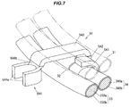
  • FIG.6 is a perspective view of a first connection terminal 51 and its peripheral part. FIG.7 is a perspective view of a fourth connection terminal 54 and its peripheral part. FIG.8 is a perspective view of a second connection terminal 52 and its peripheral part. FIG.9 is a perspective view of a third connection terminal 53 and its peripheral part. Besides, the first and second bus rings 31, 32 are shown by the two-dot chain line in FIG.7 and FIG.9 .
  • The first connection terminal 51 integrally comprises, as shown in FIG.6 , a swaging section 511 swaged at a portion where the core conductor 310a of the first bus ring 31 is exposed, a base 512 arranged on a side of one end in a circumferential direction of the first bus ring 31 in the swaging section 511, an extending portion 513 extending in a radial direction of the first to fourth bus rings 31 to 33 and the fourth bus ring 34 from a side of one end of the base 512, and a winding connection portion 514 which is formed at an opposite side of the other end of the base 512 in the extending portion 513, connected to one end of the U-phase winding 211 (cf. FIG.1 ).
  • The swaging section 511 swages the first bus ring 31 toward the direction of the rotational axis line O from an inside of the radial direction of the first bus ring 31. The base 512 is formed in a rectangular shape in which long sides are formed in the direction of the rotational axis line O and short sides are formed in the circumferential direction of the first to fourth bus rings 31 to 34.
  • The extending portion 513 extends from an end of a side of the stator 21 in a direction of the long sides of the base 512 outwardly in the radial direction of the second bus ring 32. Namely, the extending portion 513 of the first connection terminal 51 connected to the first bus ring 31 is extending across an adjacent bus ring (the second bus ring 32) in the radial direction between the swaging section 511 and the winding connection portion 514.
  • Also, both ends of the extending portion 513 (an end on the side of the base 512 and an end on the side of the winding connection portion 514) in an extending direction are bent toward an opposite side of the stator 21 in the direction of the rotational axis line O (on a side of the terminal base 20). Accordingly, the extending portion 513 is located closer to the stator 21 than the swaging section 511 and the winding connection portion 514.
  • In the present embodiment, the extending portion 513 is extending across in the direction orthogonal to the rotational axis line O between the first bus ring 31 and the fourth bus ring 34, as well as between the second bus ring 32 and the third bus ring 33 without contacting circumferential surfaces of the first to third bus rings 31 to 33 and the neutral-phase bus ring 34. Besides, it is enough for the extending portion 513 to intervene at least in a space between the second bus ring 32 and the third bus ring 33.
  • The winding connection portion 514 comprises a pair of straight portions 514a extending toward the radial direction of the first to fourth bus rings 31 to 34, and a circular-arc portion 514b having a circular-arc shape and linking the pair of straight portions 514a as one piece. In the present embodiment, the circular-arc portion 514b is located on a side of the swaging section 511 in the radial direction of the first to fourth bus rings 31 to 34. Accordingly, the winding connection portion 514 is configured to open outwardly in the radial direction of the second bus ring 32 and third bus rings 33.
  • The fourth connection terminal 54 comprises, as shown in FIG.7 , a swaging section 541 swaged at a portion where the core conductor 340a of the fourth bus ring 34 are exposed, a base 542 arranged on a side of one end in the circumferential direction of the swaging section 541 of the fourth bus ring 34, an extending portion 543 extended over the second bus ring 32 and the third bus ring 33 in the direction orthogonal to the rotational axis line O from a side of one end of the base 542, and a winding connection portion 544 which is provided at an opposite side of the base 542 in the extending portion 543, connected to each of the other ends of the U-phase winding 211, V-phase winding 212, and W-phase winding 213 (cf. FIG.1 ) as one piece.
  • The swaging section 541 swages the fourth bus ring 34 in the direction of the rotational axis line O from an inside of the axial direction of the fourth bus ring 34. The base 542 is formed in a rectangular shape in which long sides are formed in the direction of the rotational axis line O and short sides are formed in the circumferential direction of the first to fourth bus rings 31 to 34.
  • The extending portion 543 extends from an end on an opposite side of the stator 21 in a direction of the long side of the base 542 outwardly in the radial direction of the third bus ring 33. In other words, the extending portion 543 of the fourth connection terminal 54 which is connected to the fourth bus ring 34 is extended over an adjacent bus ring (the third bus ring 33) in the radial direction between the swaging section 541 and the winding connection portion 544.
  • Moreover, both ends in an extending direction of the extending portion 543 (the end on the side of the base 542 and the end on the side of the winding connection portion 544) are bent toward a side of the stator 21 in the direction of the rotational axis line O. Accordingly, the swaging section 541 and the winding connection portion 544 are located closer to the stator 21 than the extending portion 543 in the direction of the rotational axis line O.
  • In the present embodiment, the extending portion 543, likewise the extending portion 513 of the first connection terminal 51, is extending across in the direction orthogonal to the rotational axis line O between the first bus ring 31 and the fourth bus ring 34, and between the second bus ring 32 and the third bus ring 33, without contacting the circumferential surfaces of the first to third bus rings 31 to 33 and the neutral-phase bus ring 34. Besides, likewise the first connection terminal 51, it is enough for the extending portion 543 of the fourth connection terminal 54 to intervene at least in a space between the second bus ring 32 and the third bus ring 33.
  • The winding connection portion 544 integrally comprises, likewise the winding connection portion 514 of the first connection terminal 51, a pair of straight portions 544a and a circular-arc portion 514b so as to open outwardly in the radial direction of the second bus ring 32 and the third bus rings 33.
  • In the present embodiment, the first connection terminal 51 and the fourth connection terminal 54 have an identical shape, but differ from each other in an orientation of a position. In other words, the first connection terminal 51 and the fourth connection terminal 54 are composed of same shapes in all of the swaging portions 511, 541, the bases 512, 542, the extending portions 513, 543, and the winding connection portions 514,544.
  • The first connection terminal 51 is swaged to the first bus ring 31 so as to locate the extending portion 513 at the side of the stator 21 with respect to the swaging section 511 and the winding connection portion 514 in the direction of the rotational axis line O. Otherwise, the fourth connection terminal 54 is swaged to the fourth bus ring 34 so as to locate the extending portion 543 at an opposite side of the stator 21 with respect to the swaging section 511 and the winding connection portion 514 in the direction of the rotational axis line O.
  • The second connection terminal 52 integrally comprises, as shown in FIG.8 , a swaging section 521 swaged at a portion where the core conductor 320a of the second bus ring 32 is exposed, a base 522 which is provided at an a side of one end of the swaging section 521 in the circumferential direction of the second bus ring 32, and a winding connection portion 523 which is formed at one end on the side of the stator 21 in the direction of the rotational axis line O in the base 522, connected to one end of the V-phase winding 212 (cf. FIG.1 ).
  • The swaging section 521 swages the second bus ring 32 toward the direction of the rotational axis line O from an outside of the radial direction of the second bus ring 34. The base 522 is formed in a rectangular shape in which long sides are formed in the direction of the rotational axis line O and short sides are formed in a circumferential direction of the first to fourth bus rings 31 to 33 and the fourth bus ring 34.
  • The winding connection portion 523 integrally comprises, likewise the winding connection portion 514 of the first connection terminal 51 and the winding connection portion 544 of the fourth connection terminal 54, a pair of straight portions 523a and a circular-arc portion 523b so as to open outwardly in the radial direction of the second bus ring 32 and the third bus ring 33.
  • The third connection terminal 53 integrally comprises, as shown in FIG.9 , a swaging section 531 swaged at a portion where the core conductor 330a of the third bus ring 33 is exposed, a base 532 which is provided on a side of one end of the swaging section 531 in the circumferential direction of the third bus ring 33, and a winding connection portion 533 which is formed at one end of an opposite side of the stator 21 in the direction of the rotational axis line O in the base 532, connected to one end of the W-phase winding 213 (cf. FIG.1 ).
  • The swaging section 531 swages the third bus ring 33 in the direction of the rotational axis line O from an outside of the radial direction of the third bus ring 33. The base 53 comprises long sides in the direction of the rotational axis line O and short sides in the circumferential direction of the first to fourth bus rings 31 to 34.
  • The winding connection portion 533 integrally comprises, likewise the winding connection portion 523 of the second connection terminal 52, a pair of straight portions 533a and a circular-arc portion 533b so as to open outwardly in the radial direction of the second bus ring 32 and the third bus ring 33.
  • In the present embodiment, the second connection terminal 52 and the third connection terminal 53 do not include any extending portion in contrast to the configuration of the first connection terminal 51 and the fourth connection terminal 54.
  • Also, in the present embodiment, the second connection terminal 52 and the third connection terminal 53 have an identical shape, but differ from each other in an orientation of a position. That is to say, the second connection terminal 52 and the third connection terminal 53 are composed of same shapes in all of the swaging sections 521, 531, the bases 522, 532, and the winding connection portions 523, 533.
  • The second connection terminal 52 is swaged to the second bus ring 32 so as to locate the winding connection portion 523 on a side of the stator 21 with respect to the swaging section 521 in the direction of the rotational axis line O. Otherwise, the third connection terminal 53 is swaged to the third-phase bus ring 33 so as to locate the winding connection portion 533 on an opposite side of the stator 21 with respect to the swaging section 531 in the direction of the rotational axis line O.
  • (Positional relationship of the extending portions 513, 543 in the axial direction)
  • Next, a positional relationship of the extending portion 513 of the first connection terminal 51 and the extending portion 543 of the fourth connection terminal 54 in the radial direction will be explained below with referring to FIG.10A.
  • FIG.10A is an explanatory diagram for explaining the positional relationship of the extending portion 513 of the first connection terminal 51 and the extending portion 543 of the fourth connection terminal 54 in the radial direction of the second bus ring 32 an the third bus ring 33.
  • In a cross section parallel with the rotational axis line O between the second bus ring 32 and the third bus ring 33, the extending portion 513 of the first connection terminal 51 and the extending portion 543 of the fourth connection terminal 54 are configured such that a dimension d1 in the direction parallel with the rotational axis line O (an alignment direction of the second bus ring 32 and the third bus ring 33) is shorter than a dimension d2 in the direction along the circumferential direction of the first to fourth bus rings 31 to 34 (d1<d2).
  • Also, the second bus ring 32 and the extending portions 513, 543 are spaced apart from each other with a distance h so as not to interfere with each other due to e.g. vibration of a vehicle. Likewise, the third bus ring 33 and the extending portions 513, 543 are spaced apart from each other with the distance h so as not to interfere with each other due to e.g. vibration of a vehicle. In the present embodiment, the distance h is around 1 to 5 mm. Therefore, in the electric power collection/distribution ring 11 in the present embodiment, a dimension in the rotational axis line O is a total of an addition of a diameter (outer diameter) of the insulated electric wire for the second bus ring 32 and a diameter (outer diameter) of the insulated electric wire for the third bus ring 33 and a dimension of (2h+d1).
  • (Comparative example)
  • FIG.10B is an explanatory diagram showing a comparative example 1 as compared with FIG.10A. FIG.10C is an explanatory diagram showing a comparative example 2 as compared with FIG.10A.
  • As shown in FIG.10B, in the rotational axis line O, the second bus ring 32 is closer to the stator 21 than the extending portion 513 of the first connection terminal 51, and the fourth connection terminal 54 is closer to the stator 21 than the third bus ring 33. In other words, the extending portion 513 of the first connection terminal 51 and the extending portion 543 of the fourth connection terminal 54 are not interposed between the second bus ring 32 and the third bus ring 33.
  • The second bus ring 32 and the third bus ring 33, the second bus ring 32 and the extending portion 513 of the first connection terminal 51, and the third bus ring 33 and the extending portion 543 of the fourth connection terminal 54 are respectively spaced apart from each other with a distance h so as not to interfere with each other. Therefore, in the electric power collection/distribution ring 11 in the comparative example 1 as shown in FIG.10B, a dimension in the rotational axis line O is a total of an addition of a diameter (outer diameter) of the insulated electric wire for the second bus ring 32 and a diameter (outer diameter) of the insulated electric wire for the third bus ring 33 and a dimension of (3h+2d1).
  • As shown in FIG.10C, the extending portion 513 of the first connection terminal 51 and the extending portion 543 of the fourth connection terminal 54 are arranged such that, in a cross section parallel with the rotational axis line O between the second bus ring 32 and the third bus ring 33, a dimension d1 in the alignment direction of the second bus ring 32 and the third bus ring 33 is set to be d2.
  • The second bus ring 32 should be spaced apart from the extending portions 513, 543 by a distance h, and the third bus ring 33 should be spaced part from extending portions 513, 543 by a distance h, respectively. Therefore, in the electric power collection/distribution ring 11 in the comparative example 2 as shown in FIG.10C, a dimension in the rotational axis line O is a total of an addition of a diameter (outer diameter) of the insulated electric wire for the second bus ring 32 and a diameter (outer diameter) of the insulated electric wire for the third bus ring 33 and a dimension of (2h+d2).
  • (Functions and advantageous effects of the embodiment)
  • The embodiment as described above has the following functions and advantageous effects.
  • (1) The first connection terminal 51 connected to the first bus ring 31 and the fourth connection terminal 54 connected to the fourth bus ring 34 respectively have the extending portions 513, 543 that are extending across the second bus ring 32 and the third bus ring 33 in the direction orthogonal to the rotational axis line O, so that it is possible to facilitate the connection with the windings 210 drawn outside from the electric power collection/distribution ring 11 in the rotational axis line O.
  • (2) In the first connection terminal 51 and the fourth connection terminal 54, the extending portions 513, 543 are extending across in the direction orthogonal to the rotational axis line O a space between the second bus ring 32 and the third bus ring 33 that are securely spaced apart from each other with a predetermined distance, so that it is possible to reduce the thickness of the electric power collection/distribution ring 11 in the rotational axis line O as compared to the comparative example 1 as shown in FIG.10B.
  • (3) The extending portion 513 of the first connection terminal 51 and the extending portion 543 of the fourth connection terminal 54 are configured such that, in a cross section parallel with the rotational axis line O between the second bus ring 32 and the third bus ring 33, the dimension d1 in the direction parallel with the rotational axis line O is shorter than the dimension d2 in the direction along the circumferential direction of the first to fourth bus rings 31 to 34. Therefore, it is possible to reduce the thickness of the electric power collection/distribution ring 11 in the rotational axis line O as compared to the comparative example 2 as shown in FIG.10 C.
  • (Summary of the embodiment)
  • Next, technical idea understood from the embodiment as described above will be described below with using the reference numerals, etc., used in the description of the embodiment. However, each reference numeral, etc., described below is not intended to limit the constituent elements in the claims to the members, etc., specifically described in the embodiment.
    1. [1] An electric power collection/distribution ring (11), to be arranged in parallel with a stator (21) in a direction of a rotational axis line O of a rotor (22) of a three-phase alternating current electric motor (1), comprising:
      • first to fourth bus rings (31 to 34), arranged concentrically about the rotational axis line O, each of the first to fourth bus rings (31 to 33) and the neural-phase bus ring (34) being connected to a winding for each phase (211, 212, 213) in the stator (21); and
      • connection terminals (first to fourth connection terminals 51 to 54) for connecting the winding (211, 212, 213) of each phase of a stator (21) and each of the first to fourth bus rings (31 to 34),
      • wherein the first to fourth bus rings (31 to 34) are arranged such that the first bus ring (31) and the fourth bus ring (34) are arranged side by side in the direction of the rotational axis line (O) and the second bus ring (32) and the third bus ring (33) are arranged side by side in the direction of the rotational axis line (O) and the first bus ring (31) and the second bus ring (32) are arranged side by side in a direction orthogonal to the rotational axis line (O) and the third bus ring (33) and the fourth bus ring (34) are arranged side by side in the direction orthogonal to the rotational axis line (O),
      • wherein the connection terminals (51, 54) of the first and fourth bus rings (31, 34) have extending portions (513, 543) extending across the second and third bus rings (32, 33) in the direction orthogonal to the rotational axis line (O).
    2. [2] The electric power collection/distribution ring (11) according to [1], wherein the first to fourth bus rings (31 to 34) are extending across a space between the second bus ring (32) and the second bus ring (33) in the direction orthogonal to the rotational axis line (O).
    3. [3] The electric power collection/distribution ring (11) according to [2], wherein the extending portions (513, 543) are configured such that, in a cross section parallel with the rotational axis line O between the second bus ring (32) and the third bus ring (33), a dimension in the direction parallel with the rotational axis line O is shorter than a dimension in a direction along a circumferential direction of the first to fourth bus rings (31 to 34).
    4. [4] The electric power collection/distribution ring (11) according to any one of [1] to [3], wherein the extending portions (513, 543) do not contact circumferential surfaces of the first to fourth bus rings (31 to 34).
    5. [5] An electric motor (1) comprising:
      • a stator (21);
      • a rotor (22) rotatable with respect to stator (21); and
      • an electric power collection/distribution ring (11) arranged in parallel with the stator (21) in a direction of a rotational axis line O of the rotor (22),
      wherein the electric power collection/distribution ring (11) comprises:
      • first to fourth bus rings (31 to 34), arranged concentrically about the rotational axis line O, each of the first to fourth bus rings (31 to 33) and the neural-phase bus ring (34) being connected to a winding for each phase (211, 212, 213) in the stator (21); and
      • connection terminals (first to fourth connection terminals 51 to 54) for connecting the winding (211, 212, 213) of each phase of a stator (21) and each of the first to fourth bus rings (31 to 34),
      • wherein the first to fourth bus rings (31 to 34) are arranged such that the first bus ring (31) and the fourth bus ring (34) are arranged side by side in the direction of the rotational axis line (O) and the second bus ring (32) and the third bus ring (33) are arranged side by side in the direction of the rotational axis line (O) and the first bus ring (31) and the second bus ring (32) are arranged side by side in a direction orthogonal to the rotational axis line (O) and the third bus ring (33) and the fourth bus ring (34) are arranged side by side in the direction orthogonal to the rotational axis line (O),
      • wherein the connection terminals (51, 54) of the first and fourth bus rings (31, 34) have extending portions (513, 543) extending across the second and third bus rings (32, 33) in the direction orthogonal to the rotational axis line (O).
  • Although the embodiments of the invention have been described, the invention is not to be limited to the embodiments. Further, it should be noted that all combinations of the features described in the embodiments are not necessary to solve the problem of the invention.
  • The various kinds of modifications can be implemented without departing from the gist of the invention. For example, in the embodiment described above, although the winding 210 is drawn to be located at an outer side than the electric power collection/distribution ring 11 in the direction orthogonal to the rotational axis line O, the invention is not to be limited to described above, e.g., it is possible to draw the winding 210 to be located at an inner side than the electric power collection/distribution ring 11 in the direction orthogonal to the rotational axis line O.
  • Also, in the embodiment as described above, the first to fourth bus rings 31 to 34 are held by the plurality of holding members 30. The present invention is not limited thereto, and the first to fourth bus rings 31 to 34 may be held by covering with e.g. a mold resin.
  • Also, in the embodiment as described above, the extending portions 312b, 322b, 332b of the connection terminals 312, 322, 332 of the first to third bus rings 31 to 33 are extended toward the terminal base 20 which is arranged at the opposite side of the stator 21 in the direction of the rotational axis line O. The present invention is not limited to the embodiment as described above, and e.g. the extending portions 312b, 322b, 332b may be extended toward a terminal base which is arranged at the side of the stator 21 in the direction of the rotational axis line O.
  • Also, in the embodiment as described above, the connecting chips 411, 421, 431 in the first to third power supply terminals 41 to 43 are bent to be extended outwardly in the radial direction of the first to fourth bus rings 31 to 34. The present invention is not limited to the first embodiment as described above, e.g., the connecting chips 411, 421, 431 may be extended in parallel with the rotational axis line O without bending.
  • Also, in the embodiment as described above, the first to fourth connection terminals 51 to 54 are formed of separate parts different from the first to fourth bus rings 31 to 34. The present invention is not limited to the first embodiment as described above, e.g., corresponding parts to the connection terminal may be formed by bending the first to fourth bus rings 31 to 34.
  • Also, the mutual positional relationship between the first to fourth bus rings 31 to 34 is not limited to the positional relationship described in the above embodiment.
  • Also, in the embodiment as described above, the insulated electric wire is used for the first to fourth bus rings 31 to 34. The present invention is not limited to the first embodiment as described above, e.g., bare wire or bus bar formed by punching a plate etc. may be used for the first to fourth bus rings 31 to 34.
  • Also, in the embodiment as described above, the first to fourth bus rings 31 to 34 are formed in a circular shape. The present invention is not limited to the embodiment as described above, and the first to fourth bus rings 31 to 34 may be formed in e.g. elliptical shape or polygonal shape.
  • Also, in the embodiment as described above, the first to fourth bus rings 31 to 34 are formed by bending one conductive member (the insulated electric wire) in an annular shape. The present invention is not limited to the embodiment as described above, e.g., a plurality of separate conductive members connected with each other to provide an annular shape may be used for the first to fourth bus rings 31 to 34.
  • [List of Reference numerals]
  • 1:
    ELECTRIC MOTOR
    11:
    ELECTRIC POWER COLLECTION/DISTRIBUTION RING
    21:
    STATOR
    22:
    ROTOR
    31 to 34:
    FIRST TO FOURTH BUS RINGS
    51 to 54:
    CONNECTION TERMINAL
    210:
    WINDING
    211:
    U-phase WINDING
    212:
    V-phase WINDING
    213:
    W-phase WINDING
    513, 543:
    EXTENDING PORTIONS
    O:
    ROTATIONAL AXIS LINE

Claims (5)

  1. An electric power collection/distribution ring, to be arranged in parallel with a stator in a direction of a rotational axis line of a rotor of a three-phase alternating current electric motor, comprising:
    first to fourth bus rings, arranged concentrically about the rotational axis line, each of the first to fourth bus rings and the neural-phase bus ring being connected to a winding for each phase in the stator; and
    connection terminals for connecting the winding of each phase of a stator and each of the first to fourth bus rings,
    wherein the first to fourth bus rings are arranged such that the first bus ring and the fourth bus ring are arranged side by side in the direction of the rotational axis line and the second bus ring and the third bus ring are arranged side by side in the direction of the rotational axis line and the first bus ring and the second bus ring are arranged side by side in a direction orthogonal to the rotational axis line and the third bus ring and the fourth bus ring are arranged side by side in the direction orthogonal to the rotational axis line,
    wherein the connection terminals of the first and fourth bus rings have extending portions extending across the second and third bus rings in the direction orthogonal to the rotational axis line.
  2. The electric power collection/distribution ring according to claim 1, wherein the first to fourth bus rings are extending across a space between the second bus ring and the second bus ring in the direction orthogonal to the rotational axis line.
  3. The electric power collection/distribution ring according to claim 2, wherein the extending portions are configured such that, in a cross section parallel with the rotational axis line between the second bus ring and the third bus ring, a dimension in the direction parallel with the rotational axis line is shorter than a dimension in a direction along a circumferential direction of the first to fourth bus rings.
  4. The electric power collection/distribution ring according to any one of claims 1 to 3, wherein the extending portions do not contact circumferential surfaces of the first to fourth bus rings.
  5. An electric motor comprising:
    a stator;
    a rotor rotatable with respect to stator; and
    an electric power collection/distribution ring arranged in parallel with the stator in a direction of a rotational axis line of the rotor,
    wherein the electric power collection/distribution ring comprises:
    first to fourth bus rings, arranged concentrically about the rotational axis line, each of the first to fourth bus rings and the neural-phase bus ring being connected to a winding for each phase in the stator; and
    connection terminals for connecting the winding of each phase of a stator and each of the first to fourth bus rings,
    wherein the first to fourth bus rings are arranged such that the first bus ring and the fourth bus ring are arranged side by side in the direction of the rotational axis line and the second bus ring and the third bus ring are arranged side by side in the direction of the rotational axis line and the first bus ring and the second bus ring are arranged side by side in a direction orthogonal to the rotational axis line and the third bus ring and the fourth bus ring are arranged side by side in the direction orthogonal to the rotational axis line,
    wherein the connection terminals of the first and fourth bus rings have extending portions extending across the second and third bus rings in the direction orthogonal to the rotational axis line.
EP13898795.3A 2013-12-03 2013-12-03 Electric power collection/distribution ring and electric motor Withdrawn EP3079233A4 (en)

Applications Claiming Priority (1)

Application Number Priority Date Filing Date Title
PCT/JP2013/082447 WO2015083230A1 (en) 2013-12-03 2013-12-03 Electric power collection/distribution ring and electric motor

Publications (2)

Publication Number Publication Date
EP3079233A1 true EP3079233A1 (en) 2016-10-12
EP3079233A4 EP3079233A4 (en) 2017-10-04

Family

ID=53273027

Family Applications (1)

Application Number Title Priority Date Filing Date
EP13898795.3A Withdrawn EP3079233A4 (en) 2013-12-03 2013-12-03 Electric power collection/distribution ring and electric motor

Country Status (3)

Country Link
EP (1) EP3079233A4 (en)
JP (1) JP6350543B2 (en)
WO (1) WO2015083230A1 (en)

Cited By (1)

* Cited by examiner, † Cited by third party
Publication number Priority date Publication date Assignee Title
CN110971046A (en) * 2018-09-28 2020-04-07 日本电产株式会社 Electric pump device

Families Citing this family (4)

* Cited by examiner, † Cited by third party
Publication number Priority date Publication date Assignee Title
JP6577258B2 (en) * 2015-06-18 2019-09-18 矢崎総業株式会社 Feeding ring
JP6589601B2 (en) * 2015-11-27 2019-10-16 日立金属株式会社 Wiring component and method of manufacturing wiring component
JP6673518B1 (en) * 2019-07-08 2020-03-25 日立金属株式会社 Power distribution components
JP7205505B2 (en) * 2020-02-21 2023-01-17 日立金属株式会社 power distribution material

Family Cites Families (10)

* Cited by examiner, † Cited by third party
Publication number Priority date Publication date Assignee Title
JP3646856B2 (en) * 1999-07-05 2005-05-11 本田技研工業株式会社 Hybrid vehicle drive device
JP2006174547A (en) * 2004-12-14 2006-06-29 Mitsubishi Electric Corp Stator of dynamo-electric machine
JP2007174826A (en) * 2005-12-22 2007-07-05 Sumitomo Electric Ind Ltd Stator for dynamo-electric machine, insulator, and bus bar unit
JP4913538B2 (en) * 2006-10-23 2012-04-11 古河電気工業株式会社 Centralized power distribution parts
JP5026871B2 (en) * 2007-07-04 2012-09-19 本田技研工業株式会社 Lead frame structure
JP5026872B2 (en) * 2007-07-04 2012-09-19 本田技研工業株式会社 Stator
JP5333996B2 (en) * 2007-08-17 2013-11-06 株式会社安川電機 Stator and rotating electric machine using the same
JP5759238B2 (en) * 2011-04-12 2015-08-05 日立金属株式会社 Power collection and distribution ring and manufacturing method thereof
JP5810869B2 (en) * 2011-11-28 2015-11-11 トヨタ自動車株式会社 Rotating electrical machine terminal module and rotating electrical machine equipped with the same
JP5998498B2 (en) * 2012-02-06 2016-09-28 日産自動車株式会社 Power distribution component and method for manufacturing power distribution component

Cited By (1)

* Cited by examiner, † Cited by third party
Publication number Priority date Publication date Assignee Title
CN110971046A (en) * 2018-09-28 2020-04-07 日本电产株式会社 Electric pump device

Also Published As

Publication number Publication date
JP6350543B2 (en) 2018-07-04
WO2015083230A1 (en) 2015-06-11
EP3079233A4 (en) 2017-10-04
JPWO2015083230A1 (en) 2017-03-16

Similar Documents

Publication Publication Date Title
US8497618B2 (en) Stator for rotatry electrical machine including an insulating bobbin
US9318814B2 (en) Wire connection member, wire connection structure and annular power distribution member
US9419491B2 (en) Motor connecting member and motor device
US9780617B2 (en) Bus bar unit
US8922079B2 (en) Electric motor and centralized power distribution member
US7598637B2 (en) Stator for an electrical machine
US10374480B2 (en) Motor
JP5989496B2 (en) Bus ring for stator of rotating electrical machine
EP3079233A1 (en) Electric power collection/distribution ring and electric motor
US9362796B2 (en) Electricity collection and distribution ring and electric motor
US11418070B2 (en) Stator and rotary electric machine
US10396607B2 (en) Bus ring unit
EP2690757A2 (en) Electricity collection and distribution ring and electric motor
US11146136B2 (en) Bus bar assembly for electric machine winding
JP6592285B2 (en) Feeding ring
US11165301B2 (en) Interior bus bar for electric machine winding
US10938256B2 (en) Motor stator and manufacturing method thereof
US20150061433A1 (en) Electricity collection and distribution ring
JP2016059130A (en) Stator of dynamo-electric machine
US20180115211A1 (en) Rotary electric machine
JP2014090567A (en) Stator of dynamo-electric machine
EP3079232A1 (en) Electric power collection/distribution ring and electric motor
US11876414B2 (en) Electric motor comprising a wiring unit, and method for producing an electric motor comprising a wiring unit
US20210273516A1 (en) Electric motor comprising a wiring unit, and method for producing an electric motor comprising a wiring unit
JP2007202289A (en) Lead frame and power distribution part using it

Legal Events

Date Code Title Description
PUAI Public reference made under article 153(3) epc to a published international application that has entered the european phase

Free format text: ORIGINAL CODE: 0009012

17P Request for examination filed

Effective date: 20160704

AK Designated contracting states

Kind code of ref document: A1

Designated state(s): AL AT BE BG CH CY CZ DE DK EE ES FI FR GB GR HR HU IE IS IT LI LT LU LV MC MK MT NL NO PL PT RO RS SE SI SK SM TR

AX Request for extension of the european patent

Extension state: BA ME

DAX Request for extension of the european patent (deleted)
A4 Supplementary search report drawn up and despatched

Effective date: 20170906

RIC1 Information provided on ipc code assigned before grant

Ipc: H02K 3/50 20060101ALI20170831BHEP

Ipc: H02K 3/04 20060101AFI20170831BHEP

STAA Information on the status of an ep patent application or granted ep patent

Free format text: STATUS: THE APPLICATION HAS BEEN WITHDRAWN

18W Application withdrawn

Effective date: 20201215