EP2413341B1 - Push button with mechanical signal display - Google Patents
Push button with mechanical signal display Download PDFInfo
- Publication number
- EP2413341B1 EP2413341B1 EP20100007800 EP10007800A EP2413341B1 EP 2413341 B1 EP2413341 B1 EP 2413341B1 EP 20100007800 EP20100007800 EP 20100007800 EP 10007800 A EP10007800 A EP 10007800A EP 2413341 B1 EP2413341 B1 EP 2413341B1
- Authority
- EP
- European Patent Office
- Prior art keywords
- sliding
- pushbutton
- housing
- display
- contours
- Prior art date
- Legal status (The legal status is an assumption and is not a legal conclusion. Google has not performed a legal analysis and makes no representation as to the accuracy of the status listed.)
- Not-in-force
Links
Images

Classifications
-
- H—ELECTRICITY
- H01—ELECTRIC ELEMENTS
- H01H—ELECTRIC SWITCHES; RELAYS; SELECTORS; EMERGENCY PROTECTIVE DEVICES
- H01H9/00—Details of switching devices, not covered by groups H01H1/00 - H01H7/00
- H01H9/16—Indicators for switching condition, e.g. "on" or "off"
-
- H—ELECTRICITY
- H01—ELECTRIC ELEMENTS
- H01H—ELECTRIC SWITCHES; RELAYS; SELECTORS; EMERGENCY PROTECTIVE DEVICES
- H01H3/00—Mechanisms for operating contacts
- H01H3/02—Operating parts, i.e. for operating driving mechanism by a mechanical force external to the switch
- H01H3/022—Emergency operating parts, e.g. for stop-switch in dangerous conditions
Definitions
- the invention relates to a push button with a mechanical signal display for the circuit of a switching unit, comprising an actuating head and a housing, wherein the mechanical display is arranged in the actuating head and has at least one recess and a recognizable by the recess display area.
- Electromechanical command devices are widely used to operate and control machinery and equipment. They occur in various forms, for example as pushbuttons, toggle switches, key switches or emergency stop switches. Command devices are mounted on control panels, control panels, control cabinet doors or enclosure covers. By manually operating the command devices electrical switching state changes and thus the desired control effects are generated. Command devices are equipped as standard with a mechanical display to indicate prevailing switching states, the mechanical display optionally optionally or additionally equipped with a luminous or illuminated unit.
- Command devices are generally modular. That is, they consist of a push button, a fastening part, such as a ring nut or a mounting bracket and one or more switching elements, which are designed as normally closed or normally closed contacts.
- the actuator is usually guided from the front through a hole in the dash panel and mounted from behind by means of a fastening part.
- the switching elements are mechanically fastened with screws, snap hooks or bolts on the actuator or on the fastening part.
- the electrical connection of the switching elements to the controller via terminals.
- it is mandatory that the signal be sent through the Opening of positively-opening contacts is generated. This means that with an unconfirmed emergency stop command device, the contacts and thus the associated circuit are closed.
- the normally closed contact is interrupted by striking the emergency stop actuator, which is located in front of the control panel, and the system or machine is put into a safe state.
- the emergency stop actuator which is located in front of the control panel, and the system or machine is put into a safe state.
- the emergency stop command device is no longer functional. That is, in an emergency operation, the contacts are not opened and thus there is no elimination of the dangerous condition. This can lead to fatal damage to man and machine. Therefore, the secure connection between actuator and switching element is essential.
- the disadvantage of the prior art is that the mechanical display surface is guided over very delicate mechanical components that can easily tilt or deform due to the spatial tightness in the command device and as a consequence no longer allow a proper operation of the command device.
- the object of the present invention is to provide a push button with a mechanical signal display, which is structurally simple and allows reliable operation.
- the pushbutton according to the invention is designed structurally simple, but still so robust designed that ensures reliable operation is.
- the slide contours which are in operative connection with one another, are mounted on the outside of the housing, so that the interior of the pushbutton, which is already very limited anyway, can be used elsewhere.
- the outside attachment of the sliding contours, which are arranged on the one hand on the outside of the housing, and on the other on the actuating head in a partial area which is guided over the housing, has the further advantage that even if the sliding contours are damaged, the detached part does not engage in fall inside the push button and prevent actuation of the pushbutton there.
- the sliding contours are structurally kept so simple that they are preferably arranged in a plurality on the housing or on the actuating head, so that even if a sliding contour damage the other sliding contours can still work properly and the pushbutton therefore not a total must be replaced.
- the housing is designed as a rosette, so as a cylindrical basic shape.
- This body has proven to be particularly advantageous for the actuation of the actuating head, since the cylindrical shape offers no edges at which the actuating head could get caught in the actuation case.
- the sliding contour is formed on the housing as a sliding web.
- This sliding web acts as a guide web and is in operative connection with the bevelled cylinder jacket part section surface of the actuating head. After actuation of the actuating head, the slanted Zylindermantelteilab songs appearance is then arranged between two guide webs.
- the sliding webs are arranged at preferably regular intervals around the housing. This results in several Sliding contour pairs of sliding webs and bevelled cylindrical shell section areas, which allow the pushbutton to continue to be used if one of these sliding pairs is damaged.
- the sliding contour is formed on the actuating head as a chamfered cylinder jacket part portion surface. It is provided in the case of actuation that the slanted Zylindermantelteilabitess formulation slides down on an edge of a guide bar until the actuating head has arrived in the end position.
- the mechanical signal display for the status display of at least two switching states is formed. These two different switching states may be indicated by different colors, such as green and red, applied in a lid member of the actuator head which terminates in the beveled cylindrical shell portion portion.
- the sliding contours are formed from plastic. This material allows for a smooth sliding action between the beveled cylinder shell portion surfaces and the sliding webs. In addition, plastic is dimensionally stable and is not subject to major aging processes.
- the sliding contours are arranged on the outside of the housing and on the actuating head.
- the external attachment of the sliding structures results in that the interior of the pushbutton can be used elsewhere.
- sprayed plastic parts do not fall into the interior of the pushbutton, where they could oppose an actuation of the pushbutton.
- the pushbutton according to the invention is structurally simple in design, but still designed so robust that a reliable operation is guaranteed.
- the slide contours which are in operative connection with one another, are mounted on the outside of the housing, so that the interior of the pushbutton, which is already very limited anyway, can be used elsewhere.
- Another decisive advantage is that the sliding contours are structurally kept so simple that they are preferably arranged in a plurality on the housing or on the actuating head, so that even if a sliding contour damage the other sliding contours can still work properly and the pushbutton therefore not a total must be replaced.
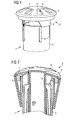
- Fig. 1 shows a pushbutton 1 according to the invention with an actuating head 2, which is formed from a cap 3 and a cover member 4, and a housing 5 which is formed as a rosette with a cylindrical base body.
- the cap 3 is preferably concentric and has a A plurality of preferably regularly arranged recesses 6, which allow a view of the underlying cover element 4.
- Below the cap 3, the lid member 4 is arranged, which is also formed concentrically and the color different display surfaces 7 provides for the switching state detection.
- the lid member 4 opens laterally into beveled cylinder shell part section surfaces 8, which serve as a sliding contour and form the first part of a sliding pair.
- Gleitstege 9 are arranged on the housing, which also serve as a sliding contour and form the second part of a sliding pair.
- the sliding webs 9 are preferably arranged regularly around the housing 5.
- Fig. 3 the cap 3 is shown with the preferably regularly arranged recesses 6. Through the recesses 6, the color differently shaped display surfaces 7 of the lid member 4 can Fig. 4 are displayed.
- the pushbutton according to the invention is structurally simple in design, but still designed so robust that a reliable operation is guaranteed.
- the slide contours which are in operative connection with one another, are mounted on the outside of the housing, so that the interior of the pushbutton, which is already very limited anyway, can be used elsewhere.
- Another decisive advantage is that the sliding contours are structurally kept so simple that they are preferably arranged in a plurality on the housing or on the actuating head, so that even if a sliding contour damage the other sliding contours can still work properly and the pushbutton therefore not a total must be replaced.
Description
Die Erfindung betrifft einen Drucktaster mit einer mechanischen Signalanzeige für die Schaltung einer Schalteinheit, aufweisend einen Betätigungskopf und ein Gehäuse, wobei die mechanische Anzeige im Betätigungskopf angeordnet ist und mindestens eine Ausnehmung aufweist sowie eine durch die Ausnehmung erkennbare Anzeigefläche.The invention relates to a push button with a mechanical signal display for the circuit of a switching unit, comprising an actuating head and a housing, wherein the mechanical display is arranged in the actuating head and has at least one recess and a recognizable by the recess display area.
Elektromechanische Befehlsgeräte werden zur Bedienung und Steuerung von Maschinen und Anlagen weitläufig verwendet. Sie treten in verschiedenen Ausprägungen, zum Beispiel als Drucktaster, Knebelschalter, Schlüsselschalter oder Not-AusSchalter auf. Befehlsgeräte werden auf Schalttafeln, Bedientableaus, Schaltschranktüren oder Gehäusedecken montiert. Durch manuelles Betätigen der Befehlsgeräte werden elektrische Schaltzustandsänderungen und damit die gewünschten Steuerungseffekte erzeugt. Befehlsgeräte werden standardmäßig mit einer mechanischen Anzeige ausgerüstet, um herrschende Schaltzustände anzuzeigen, wobei die mechanische Anzeige gegebenenfalls alternativ oder zusätzlich mit einer leuchtbaren oder beleuchteten Einheit bestückt ist.Electromechanical command devices are widely used to operate and control machinery and equipment. They occur in various forms, for example as pushbuttons, toggle switches, key switches or emergency stop switches. Command devices are mounted on control panels, control panels, control cabinet doors or enclosure covers. By manually operating the command devices electrical switching state changes and thus the desired control effects are generated. Command devices are equipped as standard with a mechanical display to indicate prevailing switching states, the mechanical display optionally optionally or additionally equipped with a luminous or illuminated unit.
Befehlsgeräte sind in der Regel modular aufgebaut. Das bedeutet, sie bestehen aus einem Druckknauf, einem Befestigungsteil, wie zum Beispiel einer Ringmutter oder einem Montagehalter und einem oder mehreren Schaltelementen, die als Öffner- oder Schließerschaltglieder ausgeführt sind. Zur Montage wird der Betätiger in der Regel von vorn durch ein Loch in der Schalttafel geführt und von hinten mittels eines Befestigungsteils montiert. Die Schaltelemente werden mit Schrauben, Schnapphaken oder Riegeln mechanisch am Betätiger oder am Befestigungsteil befestigt. Die elektrische Verbindung der Schaltelemente mit der Steuerung erfolgt über Anschlussklemmen. Bei Sicherheitsanwendungen wie zum Beispiel Not-Aus-Befehlsgeräten ist es Vorschrift, dass das Signal durch das Öffnen von zwangsöffnenden Kontakten erzeugt wird. Das heißt, dass bei einem unbetätigten Not-Aus-Befehlsgerät die Kontakte und damit der zugehörige Stromkreis geschlossen sind. Im Störungs- oder Notfall wird durch Schlagen auf den Not-Aus-Betätiger, der sich vor der Schalttafel befindet, der Öffnerkontakt unterbrochen und die Anlage oder Maschine in einen sicheren Zustand versetzt. Dies funktioniert jedoch nur, wenn die räumliche Zuordnung zwischen Betätiger und Schaltelement sichergestellt ist. Durch mangelhafte Montage oder durch Gewalteinwirkung kann es vorkommen, dass die Schaltelemente mechanisch vom Betätiger getrennt werden. In diesem Fall ist das Not-Aus-Befehlsgerät nicht mehr funktionsfähig. Das heißt, bei einer Betätigung im Notfall werden die Kontakte nicht geöffnet und damit erfolgt auch keine Beseitigung des Gefahrenzustands. Dies kann zu fatalen Schäden für Mensch und Maschine führen. Daher kommt der sicheren Verbindung zwischen Betätiger und Schaltelement eine wesentliche Bedeutung zu.Command devices are generally modular. That is, they consist of a push button, a fastening part, such as a ring nut or a mounting bracket and one or more switching elements, which are designed as normally closed or normally closed contacts. For installation, the actuator is usually guided from the front through a hole in the dash panel and mounted from behind by means of a fastening part. The switching elements are mechanically fastened with screws, snap hooks or bolts on the actuator or on the fastening part. The electrical connection of the switching elements to the controller via terminals. For safety applications such as emergency stop command devices, it is mandatory that the signal be sent through the Opening of positively-opening contacts is generated. This means that with an unconfirmed emergency stop command device, the contacts and thus the associated circuit are closed. In the event of a fault or emergency, the normally closed contact is interrupted by striking the emergency stop actuator, which is located in front of the control panel, and the system or machine is put into a safe state. However, this only works if the spatial allocation between actuator and switching element is ensured. Due to poor installation or due to the effects of force, it may happen that the switching elements are mechanically separated from the actuator. In this case, the emergency stop command device is no longer functional. That is, in an emergency operation, the contacts are not opened and thus there is no elimination of the dangerous condition. This can lead to fatal damage to man and machine. Therefore, the secure connection between actuator and switching element is essential.
Die Forderung nach einer integrierten optischen Anzeige, bei der es sich sowohl um eine mechanische und/oder elektrische Schaltanzeige handelt, führt zu einem Problem hinsichtlich der Unterbringung der erforderlichen Bauteile, da das Gesamtvolumen des Gerätes, insbesondere durch einen genormten Einbaudurchmesser (zum Beispiel 22,5 mm), nur in engen Grenzen variiert werden kann. Bisher wurde, wenn eine Integration der Anzeige in das Befehlsgerät nicht möglich war, meist eine zusätzliche Befehlsstelle, beispielsweise mit einem Leuchtmelder angebracht. Auf Grund des zusätzlichen Platzbedarfs, zum Beispiel auf einer Schalttafel der Installationseinheit und der zwingenden Verwendung einer separaten Anzeige, ist diese Lösung unvorteilhaft.The requirement for an integrated optical display, which is both a mechanical and / or electrical switching display, leads to a problem with regard to the accommodation of the required components, since the total volume of the device, in particular by a standard mounting diameter (for example 22, 5 mm), can only be varied within narrow limits. So far, if an integration of the display in the command device was not possible, usually an additional command point, for example, attached with a light. Due to the extra space required, for example on a panel of the installation unit and the mandatory use of a separate display, this solution is unfavorable.
Aus dem Stand der Technik geht dazu aus der der
Aus der
Der Nachteil am Stand der Technik besteht darin, dass die mechanische Anzeigefläche über sehr feingliedrige mechanische Bauelemente geführt ist, die auf Grund der räumlichen Enge im Befehlsgerät leicht verkanten oder sich verformen können und als Konsequenz eine vorschriftsmäßige Bedienung des Befehlsgerätes nicht mehr zulassen.The disadvantage of the prior art is that the mechanical display surface is guided over very delicate mechanical components that can easily tilt or deform due to the spatial tightness in the command device and as a consequence no longer allow a proper operation of the command device.
Demgemäß besteht die Aufgabe der vorliegenden Erfindung darin, einen Drucktaster mit einer mechanischen Signalanzeige zu schaffen, der konstruktiv einfach gehalten ist und eine zuverlässige Bedienung ermöglicht.Accordingly, the object of the present invention is to provide a push button with a mechanical signal display, which is structurally simple and allows reliable operation.
Diese Aufgabe wird durch einen Drucktaster mit den Merkmalen des Patentanspruchs 1 gelöst. Vorteilhafte Aus- und Weiterbildungen, welche einzeln oder in Kombination miteinander eingesetzt werden können, sind der Gegenstand der abhängigen Ansprüche.This object is achieved by a push-button with the features of claim 1. Advantageous embodiments and developments, which can be used individually or in combination with each other, are the subject of the dependent claims.
Erfindungsgemäß wird diese Aufgabe durch einen Drucktaster mit den Merkmalen des Anspruchs 1 gelöst.According to the invention this object is achieved by a push-button with the features of claim 1.
Der erfindungsgemäße Drucktaster ist konstruktiv einfach ausgestaltet, dabei aber trotzdem so robust ausgeführt, dass eine zuverlässige Bedienung gewährleistet ist. Die miteinander in Wirkverbindung stehenden Gleitkonturen sind gehäuseaußenseitig angebracht, so dass der sowieso schon sehr begrenzte Innenraum des Drucktasters anderweitig genutzt werden kann. Die außenseitige Anbringung der Gleitkonturen, die zum Einen an der Außenseite des Gehäuses angeordnet sind, sowie zum Anderen am Betätigungskopf in einem Teilbereich, der über dem Gehäuse geführt ist, weist den weiteren Vorteil auf, dass selbst bei Beschädigung der Gleitkonturen die abgesprungen Teil nicht in den Innenraum des Drucktasters fallen und dort eine Betätigung des Drucktasters verhindern. Ein weiterer entscheidender Vorteil besteht darin, dass die Gleitkonturen konstruktiv so einfach gehalten sind, dass sie vorzugsweise in einer Mehrzahl am Gehäuse beziehungsweise am Betätigungskopf angeordnet sind, so dass selbst bei Beschädigung einer Gleitkontur die anderen Gleitkonturen noch vorschriftsmäßig funktionieren können und der Drucktaster deswegen nicht insgesamt ausgetauscht werden muss.The pushbutton according to the invention is designed structurally simple, but still so robust designed that ensures reliable operation is. The slide contours, which are in operative connection with one another, are mounted on the outside of the housing, so that the interior of the pushbutton, which is already very limited anyway, can be used elsewhere. The outside attachment of the sliding contours, which are arranged on the one hand on the outside of the housing, and on the other on the actuating head in a partial area which is guided over the housing, has the further advantage that even if the sliding contours are damaged, the detached part does not engage in fall inside the push button and prevent actuation of the pushbutton there. Another decisive advantage is that the sliding contours are structurally kept so simple that they are preferably arranged in a plurality on the housing or on the actuating head, so that even if a sliding contour damage the other sliding contours can still work properly and the pushbutton therefore not a total must be replaced.
In einer besonders vorteilhaften Ausführungsform ist vorgesehen, dass das Gehäuse als Rosette, also als zylindrische Grundform ausgebildet ist. Dieser Grundkörper hat sich insbesondere für die Betätigung des Betätigungskopfes vorteilhaft erwiesen, da die zylindrische Form keine Kanten bietet, an denen der Betätigungskopf im Betätigungsfall verhaken könnte.In a particularly advantageous embodiment it is provided that the housing is designed as a rosette, so as a cylindrical basic shape. This body has proven to be particularly advantageous for the actuation of the actuating head, since the cylindrical shape offers no edges at which the actuating head could get caught in the actuation case.
Gemäß der Erfindung ist die Gleitkontur am Gehäuse als Gleitsteg ausgebildet. Dieser erfindungsgemäße Gleitsteg wirkt als Führungssteg und steht mit der abgeschrägten Zylindermantelteilabschnittsfläche des Betätigungskopfes in Wirkverbindung. Nach Betätigung des Betätigungskopfes ist die abgeschrägte Zylindermantelteilabschnittsfläche dann zwischen zwei Führungsstegen angeordnet.According to the invention, the sliding contour is formed on the housing as a sliding web. This sliding web according to the invention acts as a guide web and is in operative connection with the bevelled cylinder jacket part section surface of the actuating head. After actuation of the actuating head, the slanted Zylindermantelteilabschnittsfläche is then arranged between two guide webs.
In einer besonders vorteilhaften Ausführungsform ist vorgesehen, dass die Gleitstege in vorzugsweise regelmäßigen Abständen um das Gehäuse angeordnet sind. Damit ergeben sich mehrere Gleitkonturpaare aus Gleitstegen und abgeschrägten Zylindermantelteilabschnittsflächen, die es erlauben, den Drucktaster auch weiter zu verwenden, wenn eines dieser Gleitpaare beschädigt wird.In a particularly advantageous embodiment, it is provided that the sliding webs are arranged at preferably regular intervals around the housing. This results in several Sliding contour pairs of sliding webs and bevelled cylindrical shell section areas, which allow the pushbutton to continue to be used if one of these sliding pairs is damaged.
Gemäß der Erfindung ist die Gleitkontur am Betätigungskopf als abgeschrägte Zylindermantelteilabschnittsfläche ausgebildet. Dabei ist im Betätigungsfall vorgesehen, dass die abgeschrägte Zylindermantelteilabschnittsfläche an einer Kante eines Führungssteges heruntergleitet, bis der Betätigungskopf in der Endposition angelangt ist.According to the invention, the sliding contour is formed on the actuating head as a chamfered cylinder jacket part portion surface. It is provided in the case of actuation that the slanted Zylindermantelteilabschnittsfläche slides down on an edge of a guide bar until the actuating head has arrived in the end position.
In einer besonders vorteilhaften Ausführungsform ist vorgesehen, dass die mechanische Signalanzeige für die Zustandsanzeige von mindestens zwei Schaltzuständen ausgebildet ist. Diese zwei unterschiedlichen Schaltzustände können durch unterschiedliche Farben, wie zum Beispiel grün und rot, angezeigt werden, die in einem Deckelelement des Betätigungskopfes, das in die abgeschrägte Zylindermantelteilabschnittsfläche mündet, aufgetragen sind.In a particularly advantageous embodiment, it is provided that the mechanical signal display for the status display of at least two switching states is formed. These two different switching states may be indicated by different colors, such as green and red, applied in a lid member of the actuator head which terminates in the beveled cylindrical shell portion portion.
Es ist vorteilhaft, wenn die Gleitkonturen aus Kunststoff ausgebildet sind. Dieses Material ermöglicht einen leichten Gleitvorgang zwischen den abgeschrägten Zylindermantelteilabschnittsflächen und den Gleitstegen. Zudem ist Kunststoff formstabil und unterliegt keinen größeren Alterungsprozessen.It is advantageous if the sliding contours are formed from plastic. This material allows for a smooth sliding action between the beveled cylinder shell portion surfaces and the sliding webs. In addition, plastic is dimensionally stable and is not subject to major aging processes.
Gemäß der Erfindung sind die Gleitkonturen außenseitig am Gehäuse und am Betätigungskopf angeordnet. Die außenseitige Anbringung der Gleitstrukturen führt dazu, dass der Innenraum des Drucktasters anderweitig verwendet werden kann. Außerdem fallen abspritzende Kunststoffteile nicht in den Innenraum des Drucktasters, wo sie einer Betätigung des Drucktasters entgegenstehen könnten.According to the invention, the sliding contours are arranged on the outside of the housing and on the actuating head. The external attachment of the sliding structures results in that the interior of the pushbutton can be used elsewhere. In addition, sprayed plastic parts do not fall into the interior of the pushbutton, where they could oppose an actuation of the pushbutton.
Der erfindungsgemäße Drucktaster ist konstruktiv einfach ausgestaltet, dabei aber trotzdem so robust ausgeführt, dass eine zuverlässige Bedienung gewährleistet ist. Die miteinander in Wirkverbindung stehenden Gleitkonturen sind gehäuseaußenseitig angebracht, so dass der sowieso schon sehr begrenzte Innenraum des Drucktasters anderweitig genutzt werden kann. Ein weiterer entscheidender Vorteil besteht darin, dass die Gleitkonturen konstruktiv so einfach gehalten sind, dass sie vorzugsweise in einer Mehrzahl am Gehäuse beziehungsweise am Betätigungskopf angeordnet sind, so dass selbst bei Beschädigung einer Gleitkontur die anderen Gleitkonturen noch vorschriftsmäßig funktionieren können und der Drucktaster deswegen nicht insgesamt ausgetauscht werden muss.The pushbutton according to the invention is structurally simple in design, but still designed so robust that a reliable operation is guaranteed. The slide contours, which are in operative connection with one another, are mounted on the outside of the housing, so that the interior of the pushbutton, which is already very limited anyway, can be used elsewhere. Another decisive advantage is that the sliding contours are structurally kept so simple that they are preferably arranged in a plurality on the housing or on the actuating head, so that even if a sliding contour damage the other sliding contours can still work properly and the pushbutton therefore not a total must be replaced.
Weitere Vorteile und Ausführungen der Erfindung werden nachfolgend anhand von Ausführungsbeispielen sowie anhand der Zeichnung erläutert.Further advantages and embodiments of the invention will be explained below with reference to embodiments and with reference to the drawing.
Dabei zeigen schematisch:
-
Fig. 1 in einer perspektivischen Darstellung einen erfindungsgemäßen Drucktaster mit Gleitkonturen; -
Fig. 2 in einer Schnittdarstellung den Drucktaster nachFig. 1 ; -
Fig. 3 in einer Draufsicht eine Kappe des Drucktasters mit Anzeigenflächen; -
Fig. 4 in einer Draufsicht ein Deckelelement mit farblich unterschiedlichen Anzeigenflächen.
-
Fig. 1 in a perspective view of a pushbutton according to the invention with sliding contours; -
Fig. 2 in a sectional view the push button toFig. 1 ; -
Fig. 3 in a plan view of a cap of the push button with display areas; -
Fig. 4 in a plan view of a cover element with different color display surfaces.
Dieser konstruktive Aufbau geht ebenso aus
In
Der erfindungsgemäße Drucktaster ist konstruktiv einfach ausgestaltet, dabei aber trotzdem so robust ausgeführt, dass eine zuverlässige Bedienung gewährleistet ist. Die miteinander in Wirkverbindung stehenden Gleitkonturen sind gehäuseaußenseitig angebracht, so dass der sowieso schon sehr begrenzte Innenraum des Drucktasters anderweitig genutzt werden kann. Ein weiterer entscheidender Vorteil besteht darin, dass die Gleitkonturen konstruktiv so einfach gehalten sind, dass sie vorzugsweise in einer Mehrzahl am Gehäuse beziehungsweise am Betätigungskopf angeordnet sind, so dass selbst bei Beschädigung einer Gleitkontur die anderen Gleitkonturen noch vorschriftsmäßig funktionieren können und der Drucktaster deswegen nicht insgesamt ausgetauscht werden muss.The pushbutton according to the invention is structurally simple in design, but still designed so robust that a reliable operation is guaranteed. The slide contours, which are in operative connection with one another, are mounted on the outside of the housing, so that the interior of the pushbutton, which is already very limited anyway, can be used elsewhere. Another decisive advantage is that the sliding contours are structurally kept so simple that they are preferably arranged in a plurality on the housing or on the actuating head, so that even if a sliding contour damage the other sliding contours can still work properly and the pushbutton therefore not a total must be replaced.
Claims (5)
- Pushbutton (1) with a mechanical signal display for switching a switching unit, having an operating head (2), which is formed from a cap (3) and a cover element (4), and having a housing (5), wherein the mechanical display is arranged in the operating head (2) and has at least one recess (6) and also has a display area (7) which can be seen through the recess (6), wherein sliding contours (8, 9) which are operatively connected to one another are arranged on the operating head (2) and on the housing (5), characterized in that the cover element (4) opens laterally into the bevelled cylinder casing partial section surfaces (8) which serve as a sliding contour and form the first part of a sliding pair, and wherein sliding webs (9) are arranged on the outside of the housing (5) and likewise serve as a sliding contour and form the second part of a sliding pair.
- Pushbutton (1) according to Claim 1, characterized in that the housing (5) is in the form of a rosette.
- Pushbutton (1) according to Claim 1, characterized in that the sliding webs (9) are arranged at regular intervals around the housing (5).
- Pushbutton (1) according to one of the preceding claims, characterized in that the mechanical signal display is designed for displaying at least two switching states.
- Pushbutton (1) according to one of the preceding claims, characterized in that the sliding contours (8, 9) are formed from plastic.
Priority Applications (2)
| Application Number | Priority Date | Filing Date | Title |
|---|---|---|---|
| EP20100007800 EP2413341B1 (en) | 2010-07-27 | 2010-07-27 | Push button with mechanical signal display |
| CN201110210455.2A CN102412079B (en) | 2010-07-27 | 2011-07-26 | Push button with mechanical signal display |
Applications Claiming Priority (1)
| Application Number | Priority Date | Filing Date | Title |
|---|---|---|---|
| EP20100007800 EP2413341B1 (en) | 2010-07-27 | 2010-07-27 | Push button with mechanical signal display |
Publications (2)
| Publication Number | Publication Date |
|---|---|
| EP2413341A1 EP2413341A1 (en) | 2012-02-01 |
| EP2413341B1 true EP2413341B1 (en) | 2015-04-29 |
Family
ID=43334435
Family Applications (1)
| Application Number | Title | Priority Date | Filing Date |
|---|---|---|---|
| EP20100007800 Not-in-force EP2413341B1 (en) | 2010-07-27 | 2010-07-27 | Push button with mechanical signal display |
Country Status (2)
| Country | Link |
|---|---|
| EP (1) | EP2413341B1 (en) |
| CN (1) | CN102412079B (en) |
Families Citing this family (2)
| Publication number | Priority date | Publication date | Assignee | Title |
|---|---|---|---|---|
| CN106783266B (en) * | 2016-11-22 | 2019-08-09 | 南通北外滩建设工程有限公司 | Electric heater detachable switch system |
| DE102019101267A1 (en) * | 2019-01-18 | 2020-07-23 | Eaton Intelligent Power Limited | Pushbutton arrangement with identification of switching states |
Family Cites Families (5)
| Publication number | Priority date | Publication date | Assignee | Title |
|---|---|---|---|---|
| US3721789A (en) * | 1972-03-17 | 1973-03-20 | M Black | Electrical switch indicator |
| FR2716293B1 (en) * | 1994-02-14 | 1996-05-15 | Baco Const Elect | Push-turn type hook control button, in particular for action on an electrical component. |
| FR2726938B1 (en) * | 1994-11-16 | 1997-01-24 | Baco Const Elect | PUSH-PULL TYPE SNAP-ON CONTROL KNOB, PARTICULARLY FOR ACTION ON AN ELECTRICAL COMPONENT |
| US7790996B2 (en) * | 2007-07-12 | 2010-09-07 | General Electric Company | Status indication for emergency stop push button |
| DE102007046999B3 (en) | 2007-10-01 | 2009-01-02 | Siemens Ag | actuator |
-
2010
- 2010-07-27 EP EP20100007800 patent/EP2413341B1/en not_active Not-in-force
-
2011
- 2011-07-26 CN CN201110210455.2A patent/CN102412079B/en not_active Expired - Fee Related
Also Published As
| Publication number | Publication date |
|---|---|
| CN102412079B (en) | 2015-07-15 |
| CN102412079A (en) | 2012-04-11 |
| EP2413341A1 (en) | 2012-02-01 |
Similar Documents
| Publication | Publication Date | Title |
|---|---|---|
| EP2206132B1 (en) | Actuator | |
| EP3912178B1 (en) | Push-button arrangement with identification of a switching state | |
| EP2413341B1 (en) | Push button with mechanical signal display | |
| EP3533076B1 (en) | Switch device for machine tool | |
| EP1906418A1 (en) | Control device with a control device | |
| DE2810745C2 (en) | Limit switch operated by cable pull | |
| EP2478541B1 (en) | Actuator with signal display | |
| DE202011104176U1 (en) | Emergency stop switch for safety-related shutdown of electrical equipment | |
| EP2704273B1 (en) | Control and signaling device to be mounted in the mounting bore of a mounting plate | |
| EP3107211B1 (en) | Control and operation unit for an elevating work platform, a mobile working machine or a construction machine | |
| EP2296159B1 (en) | Actuator with signal display | |
| DE202012008253U1 (en) | Command and signaling device | |
| EP2704272B1 (en) | Control and signaling device to be mounted in the mounting bore of a mounting plate | |
| EP3507818B1 (en) | Holding adapter for fixing control and signalling devices and also arrangement | |
| EP2478538A1 (en) | Actuator | |
| DE102009008537B3 (en) | pushbutton | |
| DE202005018658U1 (en) | Electrical switch device e.g. for operating voltage by household installations, | |
| EP1482527B1 (en) | Push button switch | |
| EP2697542B1 (en) | Command and alert device | |
| EP3772077B1 (en) | Fixing module for a command and reporting appliance with integrated ground function | |
| WO2015158380A1 (en) | Actuator having a mechanical signal display | |
| EP2852014A1 (en) | Control and signaling device with recessed front panel installation | |
| DE202012008252U1 (en) | Command and signaling device | |
| EP2095383A1 (en) | Dust protection device for a signalling and/or command device | |
| DE202010012639U1 (en) | Installation device for the variable fixation of command and signaling devices on front panels of different thicknesses |
Legal Events
| Date | Code | Title | Description |
|---|---|---|---|
| AK | Designated contracting states |
Kind code of ref document: A1 Designated state(s): AL AT BE BG CH CY CZ DE DK EE ES FI FR GB GR HR HU IE IS IT LI LT LU LV MC MK MT NL NO PL PT RO SE SI SK SM TR |
|
| AX | Request for extension of the european patent |
Extension state: BA ME RS |
|
| PUAI | Public reference made under article 153(3) epc to a published international application that has entered the european phase |
Free format text: ORIGINAL CODE: 0009012 |
|
| 17P | Request for examination filed |
Effective date: 20120507 |
|
| RAP1 | Party data changed (applicant data changed or rights of an application transferred) |
Owner name: SIEMENS AKTIENGESELLSCHAFT |
|
| 17Q | First examination report despatched |
Effective date: 20140415 |
|
| GRAP | Despatch of communication of intention to grant a patent |
Free format text: ORIGINAL CODE: EPIDOSNIGR1 |
|
| INTG | Intention to grant announced |
Effective date: 20141205 |
|
| GRAS | Grant fee paid |
Free format text: ORIGINAL CODE: EPIDOSNIGR3 |
|
| GRAA | (expected) grant |
Free format text: ORIGINAL CODE: 0009210 |
|
| AK | Designated contracting states |
Kind code of ref document: B1 Designated state(s): AL AT BE BG CH CY CZ DE DK EE ES FI FR GB GR HR HU IE IS IT LI LT LU LV MC MK MT NL NO PL PT RO SE SI SK SM TR |
|
| REG | Reference to a national code |
Ref country code: GB Ref legal event code: FG4D Free format text: NOT ENGLISH |
|
| REG | Reference to a national code |
Ref country code: CH Ref legal event code: EP |
|
| REG | Reference to a national code |
Ref country code: AT Ref legal event code: REF Ref document number: 724836 Country of ref document: AT Kind code of ref document: T Effective date: 20150515 |
|
| REG | Reference to a national code |
Ref country code: IE Ref legal event code: FG4D Free format text: LANGUAGE OF EP DOCUMENT: GERMAN |
|
| REG | Reference to a national code |
Ref country code: DE Ref legal event code: R096 Ref document number: 502010009418 Country of ref document: DE Effective date: 20150603 |
|
| REG | Reference to a national code |
Ref country code: NL Ref legal event code: VDEP Effective date: 20150429 |
|
| REG | Reference to a national code |
Ref country code: LT Ref legal event code: MG4D |
|
| PG25 | Lapsed in a contracting state [announced via postgrant information from national office to epo] |
Ref country code: NL Free format text: LAPSE BECAUSE OF FAILURE TO SUBMIT A TRANSLATION OF THE DESCRIPTION OR TO PAY THE FEE WITHIN THE PRESCRIBED TIME-LIMIT Effective date: 20150429 |
|
| PG25 | Lapsed in a contracting state [announced via postgrant information from national office to epo] |
Ref country code: ES Free format text: LAPSE BECAUSE OF FAILURE TO SUBMIT A TRANSLATION OF THE DESCRIPTION OR TO PAY THE FEE WITHIN THE PRESCRIBED TIME-LIMIT Effective date: 20150429 Ref country code: PT Free format text: LAPSE BECAUSE OF FAILURE TO SUBMIT A TRANSLATION OF THE DESCRIPTION OR TO PAY THE FEE WITHIN THE PRESCRIBED TIME-LIMIT Effective date: 20150831 Ref country code: LT Free format text: LAPSE BECAUSE OF FAILURE TO SUBMIT A TRANSLATION OF THE DESCRIPTION OR TO PAY THE FEE WITHIN THE PRESCRIBED TIME-LIMIT Effective date: 20150429 Ref country code: FI Free format text: LAPSE BECAUSE OF FAILURE TO SUBMIT A TRANSLATION OF THE DESCRIPTION OR TO PAY THE FEE WITHIN THE PRESCRIBED TIME-LIMIT Effective date: 20150429 Ref country code: NO Free format text: LAPSE BECAUSE OF FAILURE TO SUBMIT A TRANSLATION OF THE DESCRIPTION OR TO PAY THE FEE WITHIN THE PRESCRIBED TIME-LIMIT Effective date: 20150729 Ref country code: HR Free format text: LAPSE BECAUSE OF FAILURE TO SUBMIT A TRANSLATION OF THE DESCRIPTION OR TO PAY THE FEE WITHIN THE PRESCRIBED TIME-LIMIT Effective date: 20150429 |
|
| PG25 | Lapsed in a contracting state [announced via postgrant information from national office to epo] |
Ref country code: LV Free format text: LAPSE BECAUSE OF FAILURE TO SUBMIT A TRANSLATION OF THE DESCRIPTION OR TO PAY THE FEE WITHIN THE PRESCRIBED TIME-LIMIT Effective date: 20150429 Ref country code: IS Free format text: LAPSE BECAUSE OF FAILURE TO SUBMIT A TRANSLATION OF THE DESCRIPTION OR TO PAY THE FEE WITHIN THE PRESCRIBED TIME-LIMIT Effective date: 20150829 Ref country code: GR Free format text: LAPSE BECAUSE OF FAILURE TO SUBMIT A TRANSLATION OF THE DESCRIPTION OR TO PAY THE FEE WITHIN THE PRESCRIBED TIME-LIMIT Effective date: 20150730 |
|
| PG25 | Lapsed in a contracting state [announced via postgrant information from national office to epo] |
Ref country code: EE Free format text: LAPSE BECAUSE OF FAILURE TO SUBMIT A TRANSLATION OF THE DESCRIPTION OR TO PAY THE FEE WITHIN THE PRESCRIBED TIME-LIMIT Effective date: 20150429 Ref country code: DK Free format text: LAPSE BECAUSE OF FAILURE TO SUBMIT A TRANSLATION OF THE DESCRIPTION OR TO PAY THE FEE WITHIN THE PRESCRIBED TIME-LIMIT Effective date: 20150429 |
|
| REG | Reference to a national code |
Ref country code: DE Ref legal event code: R097 Ref document number: 502010009418 Country of ref document: DE |
|
| PG25 | Lapsed in a contracting state [announced via postgrant information from national office to epo] |
Ref country code: CZ Free format text: LAPSE BECAUSE OF FAILURE TO SUBMIT A TRANSLATION OF THE DESCRIPTION OR TO PAY THE FEE WITHIN THE PRESCRIBED TIME-LIMIT Effective date: 20150429 Ref country code: SK Free format text: LAPSE BECAUSE OF FAILURE TO SUBMIT A TRANSLATION OF THE DESCRIPTION OR TO PAY THE FEE WITHIN THE PRESCRIBED TIME-LIMIT Effective date: 20150429 Ref country code: PL Free format text: LAPSE BECAUSE OF FAILURE TO SUBMIT A TRANSLATION OF THE DESCRIPTION OR TO PAY THE FEE WITHIN THE PRESCRIBED TIME-LIMIT Effective date: 20150429 Ref country code: RO Free format text: LAPSE BECAUSE OF NON-PAYMENT OF DUE FEES Effective date: 20150429 Ref country code: MC Free format text: LAPSE BECAUSE OF FAILURE TO SUBMIT A TRANSLATION OF THE DESCRIPTION OR TO PAY THE FEE WITHIN THE PRESCRIBED TIME-LIMIT Effective date: 20150429 |
|
| REG | Reference to a national code |
Ref country code: CH Ref legal event code: PL |
|
| PLBE | No opposition filed within time limit |
Free format text: ORIGINAL CODE: 0009261 |
|
| STAA | Information on the status of an ep patent application or granted ep patent |
Free format text: STATUS: NO OPPOSITION FILED WITHIN TIME LIMIT |
|
| GBPC | Gb: european patent ceased through non-payment of renewal fee |
Effective date: 20150729 |
|
| PG25 | Lapsed in a contracting state [announced via postgrant information from national office to epo] |
Ref country code: LU Free format text: LAPSE BECAUSE OF FAILURE TO SUBMIT A TRANSLATION OF THE DESCRIPTION OR TO PAY THE FEE WITHIN THE PRESCRIBED TIME-LIMIT Effective date: 20150727 |
|
| 26N | No opposition filed |
Effective date: 20160201 |
|
| REG | Reference to a national code |
Ref country code: IE Ref legal event code: MM4A |
|
| PG25 | Lapsed in a contracting state [announced via postgrant information from national office to epo] |
Ref country code: IT Free format text: LAPSE BECAUSE OF FAILURE TO SUBMIT A TRANSLATION OF THE DESCRIPTION OR TO PAY THE FEE WITHIN THE PRESCRIBED TIME-LIMIT Effective date: 20150429 Ref country code: GB Free format text: LAPSE BECAUSE OF NON-PAYMENT OF DUE FEES Effective date: 20150729 Ref country code: CH Free format text: LAPSE BECAUSE OF NON-PAYMENT OF DUE FEES Effective date: 20150731 Ref country code: LI Free format text: LAPSE BECAUSE OF NON-PAYMENT OF DUE FEES Effective date: 20150731 |
|
| PG25 | Lapsed in a contracting state [announced via postgrant information from national office to epo] |
Ref country code: SI Free format text: LAPSE BECAUSE OF FAILURE TO SUBMIT A TRANSLATION OF THE DESCRIPTION OR TO PAY THE FEE WITHIN THE PRESCRIBED TIME-LIMIT Effective date: 20150429 |
|
| REG | Reference to a national code |
Ref country code: FR Ref legal event code: PLFP Year of fee payment: 7 |
|
| PG25 | Lapsed in a contracting state [announced via postgrant information from national office to epo] |
Ref country code: IE Free format text: LAPSE BECAUSE OF NON-PAYMENT OF DUE FEES Effective date: 20150727 |
|
| REG | Reference to a national code |
Ref country code: AT Ref legal event code: MM01 Ref document number: 724836 Country of ref document: AT Kind code of ref document: T Effective date: 20150727 |
|
| PG25 | Lapsed in a contracting state [announced via postgrant information from national office to epo] |
Ref country code: AT Free format text: LAPSE BECAUSE OF NON-PAYMENT OF DUE FEES Effective date: 20150727 |
|
| PG25 | Lapsed in a contracting state [announced via postgrant information from national office to epo] |
Ref country code: MT Free format text: LAPSE BECAUSE OF FAILURE TO SUBMIT A TRANSLATION OF THE DESCRIPTION OR TO PAY THE FEE WITHIN THE PRESCRIBED TIME-LIMIT Effective date: 20150429 |
|
| PG25 | Lapsed in a contracting state [announced via postgrant information from national office to epo] |
Ref country code: SM Free format text: LAPSE BECAUSE OF FAILURE TO SUBMIT A TRANSLATION OF THE DESCRIPTION OR TO PAY THE FEE WITHIN THE PRESCRIBED TIME-LIMIT Effective date: 20150429 Ref country code: BG Free format text: LAPSE BECAUSE OF FAILURE TO SUBMIT A TRANSLATION OF THE DESCRIPTION OR TO PAY THE FEE WITHIN THE PRESCRIBED TIME-LIMIT Effective date: 20150429 Ref country code: HU Free format text: LAPSE BECAUSE OF FAILURE TO SUBMIT A TRANSLATION OF THE DESCRIPTION OR TO PAY THE FEE WITHIN THE PRESCRIBED TIME-LIMIT; INVALID AB INITIO Effective date: 20100727 |
|
| PG25 | Lapsed in a contracting state [announced via postgrant information from national office to epo] |
Ref country code: CY Free format text: LAPSE BECAUSE OF FAILURE TO SUBMIT A TRANSLATION OF THE DESCRIPTION OR TO PAY THE FEE WITHIN THE PRESCRIBED TIME-LIMIT Effective date: 20150429 Ref country code: SE Free format text: LAPSE BECAUSE OF FAILURE TO SUBMIT A TRANSLATION OF THE DESCRIPTION OR TO PAY THE FEE WITHIN THE PRESCRIBED TIME-LIMIT Effective date: 20150429 |
|
| REG | Reference to a national code |
Ref country code: FR Ref legal event code: PLFP Year of fee payment: 8 |
|
| PG25 | Lapsed in a contracting state [announced via postgrant information from national office to epo] |
Ref country code: BE Free format text: LAPSE BECAUSE OF NON-PAYMENT OF DUE FEES Effective date: 20150731 |
|
| PG25 | Lapsed in a contracting state [announced via postgrant information from national office to epo] |
Ref country code: TR Free format text: LAPSE BECAUSE OF FAILURE TO SUBMIT A TRANSLATION OF THE DESCRIPTION OR TO PAY THE FEE WITHIN THE PRESCRIBED TIME-LIMIT Effective date: 20150429 |
|
| PG25 | Lapsed in a contracting state [announced via postgrant information from national office to epo] |
Ref country code: MK Free format text: LAPSE BECAUSE OF FAILURE TO SUBMIT A TRANSLATION OF THE DESCRIPTION OR TO PAY THE FEE WITHIN THE PRESCRIBED TIME-LIMIT Effective date: 20150429 |
|
| REG | Reference to a national code |
Ref country code: FR Ref legal event code: PLFP Year of fee payment: 9 |
|
| PG25 | Lapsed in a contracting state [announced via postgrant information from national office to epo] |
Ref country code: AL Free format text: LAPSE BECAUSE OF FAILURE TO SUBMIT A TRANSLATION OF THE DESCRIPTION OR TO PAY THE FEE WITHIN THE PRESCRIBED TIME-LIMIT Effective date: 20150429 |
|
| PGFP | Annual fee paid to national office [announced via postgrant information from national office to epo] |
Ref country code: DE Payment date: 20190919 Year of fee payment: 10 Ref country code: FR Payment date: 20190716 Year of fee payment: 10 |
|
| REG | Reference to a national code |
Ref country code: DE Ref legal event code: R119 Ref document number: 502010009418 Country of ref document: DE |
|
| PG25 | Lapsed in a contracting state [announced via postgrant information from national office to epo] |
Ref country code: FR Free format text: LAPSE BECAUSE OF NON-PAYMENT OF DUE FEES Effective date: 20200731 |
|
| PG25 | Lapsed in a contracting state [announced via postgrant information from national office to epo] |
Ref country code: DE Free format text: LAPSE BECAUSE OF NON-PAYMENT OF DUE FEES Effective date: 20210202 |