EP2413151B1 - Method for calculating the state of charge of a sodium-sulfur battery - Google Patents
Method for calculating the state of charge of a sodium-sulfur battery Download PDFInfo
- Publication number
- EP2413151B1 EP2413151B1 EP10755778.7A EP10755778A EP2413151B1 EP 2413151 B1 EP2413151 B1 EP 2413151B1 EP 10755778 A EP10755778 A EP 10755778A EP 2413151 B1 EP2413151 B1 EP 2413151B1
- Authority
- EP
- European Patent Office
- Prior art keywords
- charge
- sodium
- sulfur battery
- capacity
- discharge
- Prior art date
- Legal status (The legal status is an assumption and is not a legal conclusion. Google has not performed a legal analysis and makes no representation as to the accuracy of the status listed.)
- Active
Links
Images


Classifications
-
- G—PHYSICS
- G01—MEASURING; TESTING
- G01R—MEASURING ELECTRIC VARIABLES; MEASURING MAGNETIC VARIABLES
- G01R31/00—Arrangements for testing electric properties; Arrangements for locating electric faults; Arrangements for electrical testing characterised by what is being tested not provided for elsewhere
- G01R31/36—Arrangements for testing, measuring or monitoring the electrical condition of accumulators or electric batteries, e.g. capacity or state of charge [SoC]
- G01R31/378—Arrangements for testing, measuring or monitoring the electrical condition of accumulators or electric batteries, e.g. capacity or state of charge [SoC] specially adapted for the type of battery or accumulator
-
- G—PHYSICS
- G01—MEASURING; TESTING
- G01R—MEASURING ELECTRIC VARIABLES; MEASURING MAGNETIC VARIABLES
- G01R31/00—Arrangements for testing electric properties; Arrangements for locating electric faults; Arrangements for electrical testing characterised by what is being tested not provided for elsewhere
- G01R31/36—Arrangements for testing, measuring or monitoring the electrical condition of accumulators or electric batteries, e.g. capacity or state of charge [SoC]
- G01R31/382—Arrangements for monitoring battery or accumulator variables, e.g. SoC
-
- H—ELECTRICITY
- H01—ELECTRIC ELEMENTS
- H01M—PROCESSES OR MEANS, e.g. BATTERIES, FOR THE DIRECT CONVERSION OF CHEMICAL ENERGY INTO ELECTRICAL ENERGY
- H01M10/00—Secondary cells; Manufacture thereof
- H01M10/36—Accumulators not provided for in groups H01M10/05-H01M10/34
- H01M10/39—Accumulators not provided for in groups H01M10/05-H01M10/34 working at high temperature
- H01M10/3909—Sodium-sulfur cells
-
- G—PHYSICS
- G01—MEASURING; TESTING
- G01R—MEASURING ELECTRIC VARIABLES; MEASURING MAGNETIC VARIABLES
- G01R31/00—Arrangements for testing electric properties; Arrangements for locating electric faults; Arrangements for electrical testing characterised by what is being tested not provided for elsewhere
- G01R31/36—Arrangements for testing, measuring or monitoring the electrical condition of accumulators or electric batteries, e.g. capacity or state of charge [SoC]
- G01R31/396—Acquisition or processing of data for testing or for monitoring individual cells or groups of cells within a battery
-
- Y—GENERAL TAGGING OF NEW TECHNOLOGICAL DEVELOPMENTS; GENERAL TAGGING OF CROSS-SECTIONAL TECHNOLOGIES SPANNING OVER SEVERAL SECTIONS OF THE IPC; TECHNICAL SUBJECTS COVERED BY FORMER USPC CROSS-REFERENCE ART COLLECTIONS [XRACs] AND DIGESTS
- Y02—TECHNOLOGIES OR APPLICATIONS FOR MITIGATION OR ADAPTATION AGAINST CLIMATE CHANGE
- Y02E—REDUCTION OF GREENHOUSE GAS [GHG] EMISSIONS, RELATED TO ENERGY GENERATION, TRANSMISSION OR DISTRIBUTION
- Y02E60/00—Enabling technologies; Technologies with a potential or indirect contribution to GHG emissions mitigation
- Y02E60/10—Energy storage using batteries
Definitions
- the present invention relates to a method for accurately calculating the state of charge of a sodium-sulfur battery.
- a sodium-sulfur battery may be given as one example of electric power storage devices which are expected to be used more and more in various application fields, such as electric-load leveling, measures against a momentary drop in power, or compensation for fluctuations in the power generated by a natural energy generating system.
- Such a sodium-sulfur battery is generally configured in such a manner that a plurality of electric cells is connected in series to form a string, a plurality of thus connected strings is connected in parallel to form a block, a plurality of thus connected blocks is connected in series to form a module, and finally a plurality of thus connected modules is connected in series.
- the operating cycle of the sodium-sulfur battery in case of the application of the load leveling, for example, is a repetition of a cycle consisting of a discharge and a charge with intervening an idle period there between.
- JP-A-08-017478 may be given as an example of a prior art. Other examples are given by JP 2000 048865 A , US 2001/048286 A1 , JP 9 318716 A , JP 3 158781 A , and JP 2008 251291 A .
- the rated capacity of the sodium-sulfur battery decreases due to the increase in the residual capacity by the deterioration or the like of electric cells, this would generate an error between the state of charge calculated by the integration and the actual state of charge, and would make it impossible to accurately calculate a true state of charge.
- the failure to accurately calculate the true state of charge is apt to operate the sodium-sulfur battery, with deviating from its operational range. This may lead to an overdischarge or an overcharge, eventually causing a vicious circle of further deterioration or the like of the electric cells.
- the product capacity (absolute capacity) of a sodium-sulfur battery is provided with an electrical tolerance so as to restrain a drop in the rated capacity of the sodium-sulfur battery caused by possible deterioration or the like of electric cells, thereby securing the rated capacity until the final year of the expected life thereof.
- the state of charge should exceed the rated capacity at the end of the charge if the integrated charge currents are added to the state of charge at the initial stage of delivering the battery, which is designed by taking the increase of the residual capacity after the lapse of several years into consideration.
- the present invention has been made with a view of the background described above and it is an object of the invention to provide a means which is applicable to the compensation for fluctuations in power generated by a natural energy generating device and which permits accurate and precise calculation of the state of charge of a sodium-sulfur battery. Studies have revealed that the object can be fulfilled by the following means.
- the method for calculating the state of charge of a sodium-sulfur battery according to the present invention is a method for calculating the current state of charge of a sodium-sulfur battery.
- the term "current” here means the point of time at which the calculation is about to start. The same meaning applies a current residual capacity Qsc of a block and the like, which will be described hereinafter.
- the state of charge is a dischargeable electrical quantity [Ah] remaining in the sodium-sulfur battery, and it is a management value.
- the method for calculating the state of charge of a sodium-sulfur battery according to the present invention may be said to be a means for matching the state of charge, which is a management value, to a true (actual) state of charge.
- the product capacity is an electrical quantity [Ah] that a sodium-sulfur battery can absolutely have, and is also called an absolute capacity.
- the product capacity is a designed value (fixed value).
- the residual capacity is an electrical quantity [Ah] that remains in the sodium-sulfur battery with age and cannot be discharged.
- An equivalent cycle determines the value of the residual capacity (refer to Fig. 7 , which will be discussed hereinafter).
- the number of the equivalent cycles corresponds to the number of cycles of discharges at a rated capacity (Ah). A discharge carried out is always followed by a charge (for the next discharge), which explains why it is called a cycle. If the yearly numbers of discharges carried out at the rated capacity (Ah) are uniform, then the equivalent cycles can be replaced by the number of lapse years. The final year means the final year in an expected life.
- the used capacity is an electrical quantity [Ah] (considered) to have been (actually) discharged by the sodium-sulfur battery, and this is a management value determined by calculation.
- the electrical quantity [Ah] that can be discharged by the sodium-sulfur battery is referred to as an available capacity.
- the rated capacity is a (specified) available capacity peculiar to each sodium-sulfur battery.
- the used capacity changes within the range of an available capacity.
- the used capacity is set again (reset) to 0 [Ah] at the end of a charge and determined by adding up currents from that point (e.g., "+" for a discharge current or "-" for a charge current).
- the used capacity for calculating the state of charge is desirably reset also at the end of a discharge as shown below. In this case, it is not of course reset to 0 [Ah].
- the used capacity Qu [Ah] is reset to 0 [Ah] at the end of a charge and also reset according to expression (3) given below in a single-phase region after the completion of a discharge.
- Qu Qn ⁇ Qsc
- the method for calculating the state of charge of a sodium-sulfur battery according to the present invention is preferably used in the case where the sodium-sulfur battery, the state of charge of which is to be calculated, is a sodium-sulfur battery which constitutes a power storage compensating unit in an interconnected system, which combines a power generating unit incurring output fluctuations and the power storage compensating unit to supply power to a power system, and which compensates for the output fluctuations of the power generating unit.
- whether or not a certain region is a single-phase region is determined by determining whether or not the region is a region in which a voltage drops in the relationship between a depth of charge and a voltage (which will be discussed in more detail hereinafter).
- a determination voltage may be set beforehand to determine whether or not a region is the single-phase region so as to determine that a certain region is a single-phase region if a voltage drops to the preset voltage or less.
- the value of the determination voltage may be set to be slightly lower (by a predetermined value) than a predetermined voltage in a two-phase region.
- temperature means a battery operating temperature or more specifically, the temperature in a module during an operation.
- the method for calculating the state of charge of a sodium-sulfur battery according to the present invention determines the state of charge of the sodium-sulfur battery according to the aforesaid expression (1).
- (Qa-Qsf) corresponds to the available capacity in the final year. The available capacity always remains constant, however, in the final year, the electrical tolerance (which will be discussed later) is 0 (zero), so that the available capacity is determined by calculating Qa-Qsf.
- expression (1) determines the (current) state of charge on the basis of the ratio of the (current) used capacity to the available capacity, thus making it always possible to calculate an accurate state of charge independently of changes in the residual capacity with the lapse of year.
- a state of charge can be precisely calculated, thus protecting a sodium-sulfur battery from being operated beyond an operational range and also preventing the battery from being overdischarged or overcharged. This makes it possible to avoid a vicious circle in which an overdischarge or an overcharge results in further deterioration or the like of electric cells.
- the used capacity is reset at regular intervals against an error which is incurred during the measurement of a charge current and a discharge current, and even expanded in integration.
- This arrangement prevents an increase in an error also in the state of charge determined on the basis of the used capacity, making it possible to calculate the state of charge more accurately than in the case where the method for calculating the state of charge of a sodium-sulfur battery according to the present invention is not used.
- a used capacity is reset according to expression (3) in a single-phase region after completion of a discharge (at the side of a discharge end), and the current used capacity is reset on the basis of the (current) depth of charge of a normal block determined from a block voltage and a current block residual capacity.
- the state of charge calculated according to expression (1) on the basis of the (current) used capacity will have a more accurate value as a current state of charge, compared with the case where the preferred embodiment of the present inventive method for calculating the state of charge of the sodium-sulfur battery is not employed.
- Figure 1 is a circuit diagram illustrating an example of a module constituting the sodium-sulfur battery.
- Figure 2 is a graph illustrating the relationship between depth of charge and voltage of the sodium-sulfur battery.
- Fig. 3 is a conceptual diagram illustrating the deterioration of the sodium-sulfur battery with lapse of time.
- a sodium-sulfur battery 3 has a plurality of (an m number of) modules 34 shown in Fig. 1 .
- Each of the modules 34 is constructed of a plurality of (an n number of) blocks 33 connected in series, each of the blocks 33 is constructed of a plurality of (a u number of) strings 32 connected in parallel, and each of the strings 32 is constructed of a plurality of (an s number of) electric cells 31 connected in series.
- the electric cell 31 has molten metal sodium, which is a cathode active material, and molten sulfur, which is an anode active material.
- the cathode active material and the anode active material are isolated by a beta alumina solid electrolyte, which has a selective permeability with respect to sodium ions.
- the sodium-sulfur battery is a high-temperature secondary battery operated at about 280°C to about 350°C (around 300°C).
- the molten sodium emits electrons and turns into a sodium ion, which moves to the anode side through a solid electrolyte tube so as to react with sulfur and electrons having passed through an external circuit to generate sodium polysulfide, thereby generating a voltage of approximately 2V in the electric cell 31.
- the reaction to produce sodium and sulfur takes place in a charge.
- the operating cycle of the sodium-sulfur battery consists of the repetition of a cycle of the aforesaid discharge and charge with a rest between the cycles when the battery is used in, for example, a load leveling application.
- the voltage (e.g., a block voltage) while the sodium-sulfur battery is in operation remains almost constant except for the vicinity of the end of a charge or a discharge.
- the voltage obviously rises toward the end of the charge and obviously falls toward the end of the discharge with a reduction in the molar proportion of sulfur.
- the composition of the sodium polysulfide generated at the positive electrode changes according to a depth of charge. The changes in the composition are grasped in terms of the value of x of Na 2 S x .
- the positive electrode In a fully charged state, the positive electrode has a two-phase region wherein S and Na 2 S 5 coexist.
- a sodium-sulfur battery in a virgin state cannot be fully charged 100% although the depth of charge (the depth of charge during an operation) is fixed, and the (ageing) residual capacity that prevents a full charge increases as time passes, as illustrated in Fig. 3 .
- an electrical tolerance is considered for an available capacity, so that the electrical tolerance compensates for an increase in the residual capacity thereby to secure the available capacity until the final year (expected life) is reached.
- the electrical tolerance refers to the capacity obtained by subtracting the residual capacity and the available capacity from the product capacity.
- the method for calculating the state of charge of a sodium-sulfur battery according to the present invention will now be described by taking, as an example, the case of the sodium-sulfur battery 3 illustrated in Fig. 1 .
- the number (the series number) of the modules 34 of the sodium-sulfur battery 3 is ten
- the number (the series number) of the blocks 33 constituting the module 34 is four
- the number (the parallel number) of the strings 32 constituting the block 33 is twelve
- the number (the series number) of the electric cells 31 constituting the string 32 is eight.
- the product capacity Qa denotes a designed value
- the used capacity Qu denotes a value determined by integrating the currents related to charges and discharges (e.g., discharge currents are indicated by "+” and charge currents are indicated by "-") of the sodium-sulfur battery.
- Figure 7 is a graph, which illustrates the relationship between residual capacity [Ah] and equivalent cycle (the number of cycles) [cycle] and which shows that the residual capacity increases as discharges are repeated (with lapse of time).
- the equivalent cycle in the final year (Cef) is set, the residual capacity in the final year (Qsf) may be obtained.
- the residual capacity means a residual capacity of an electric cell.
- the used capacity Qu in expression (1) is reset to 0 [Ah] at the end of a charge.
- the end of a charge can be generally judged by checking whether or not the voltage of a block 33 has reached a charge end cut voltage VH shown by expression (6) given below during a charge.
- VH 8 ⁇ 2.075 + ⁇ + I ⁇ R
- auxiliary charge described in JP 3505116 it is preferably to take the auxiliary charge described in JP 3505116 into consideration. For example, when the final auxiliary charge stage described in JP 3505116 is reached, it may be judged as the end of a charge.
- the used capacity Qu in expression (1) is reset according to expression (3) given below in a single-phase region after completion of a discharge.
- Qu Qn ⁇ Qsc
- the depth of charge Qn [Ah] of a normal block in expression (3) is get according to expression (4') given below.
- Qn 12 ⁇ f 2 V 5 0, 5, T , Id where f2(V5(0.5, T, Id)): conversion function for determining the depth of charge [Ah] of the block 33 based on the voltage [V] of the block 33 of the module 34 of, for example, a fifth highest voltage after having comparing blocks each showing the highest voltage in each of the modules (The voltage [V] is to be obtained by converting into a stable open-circuit voltage [V] based on an unstable open-circuit voltage [V] measured after 30 minutes (0.5 hours) have passed since the completion of a discharge in the single-phase region and then correcting the converted stable open-circuit voltage [V] on the basis of a temperature T[°C] upon completion of the discharge and a discharge current Id[A] upon completion of
- the method for calculating the state of charge of the sodium-sulfur battery according to the present invention uses a means for determining the (true, stabilized) open-circuit voltage at the end of a discharge on the basis of the transient voltage indicated by the sodium-sulfur battery after the completion of the discharge.
- the open-circuit voltage at this time is referred to as the 30-minute rest OCV (Open Circuit Voltage).
- the 30-minute rest OCV is converted into the open-circuit voltage [V] of the block 33 after the lapse of, for example, two hours.
- This open-circuit voltage is referred to as the two-hour rest OCV and considered to be the true open-circuit voltage value (before the correction based on the temperature and the discharge current).
- each OCV is indicated as the OCV of an electric cell, as is clear from the numerical values on the axis of ordinates and the axis of abscissas.
- a further correction is made on the basis of the temperature T[°C] and the discharge current Id[A] upon the completion of the discharge to determine the true open-circuit voltage value of the block.
- the correction can be made on the basis of the point that the value of (the two-hour rest OCV - the 30-minute rest OCV)[V] and the temperature T[°C] and the discharge current [A] have a predetermined relationship.
- the value of (the two-hour rest OCV - the 30-minute rest OCV)[V] is a correction value (a value to be corrected), and the value to be corrected is the two-hour rest OCV (before correction) [V] determined on the basis of the 30-minute rest OCV.
- x denotes temperature
- y denotes (the two-hour rest OCV - the 30-minute rest OCV). According to Fig. 5 , if the temperature rises by, for example, 10°C, then a correction of approximately -0.004V (-4mV) is required.
- x denotes discharge current
- y denotes (the two-hour rest OCV - the 30minute rest OCV). According to Fig. 6 , if the discharge current increases by, for example, 10A, then a correction of approximately +0.003V (3mV) is required.
- the voltages of the blocks 33 constituting the module 34 are determined to identify the block 33 having a highest voltage [V]. Then, based on the (highest) voltage of the block 33 determined in each of the modules 34, the comparison among the modules 34 is carried out to determine the voltage of the block 33 in the module 34 having (for example) a fifth highest voltage.
- the determined voltage [V] is converted into the depth of charge [Ah].
- the voltage is based on a voltage measured in the single-phase region, so that the voltage [V] can be converted into the depth of charge [Ah] (refer to Fig. 2 ).
- the depth of charge (capacity) is based on the voltage of the block 33 and therefore equivalent to the capacity of a single string 32.
- multiplying the depth of charge by twelve, which is the number of the strings 32 determines the depth of charge [Ah] of the block, which is a normal block depth of charge Qn [Ah].
- the current block residual capacity (Qsc) may be determined.
- the residual capacity in Fig. 7 is the residual capacity of an electric cell.
- the method for calculating the state of charge of a sodium-sulfur battery according to the present invention may be preferable used as a means for accurately and precisely calculating the current state of charge of a sodium-sulfur battery used for applications, such as load leveling, measures against a momentary drop in power, or compensation for fluctuations in the power generated by a natural energy generating system.
Landscapes
- Physics & Mathematics (AREA)
- General Physics & Mathematics (AREA)
- Engineering & Computer Science (AREA)
- Manufacturing & Machinery (AREA)
- Chemical & Material Sciences (AREA)
- Chemical Kinetics & Catalysis (AREA)
- Electrochemistry (AREA)
- General Chemical & Material Sciences (AREA)
- Secondary Cells (AREA)
Description
- The present invention relates to a method for accurately calculating the state of charge of a sodium-sulfur battery.
- A sodium-sulfur battery may be given as one example of electric power storage devices which are expected to be used more and more in various application fields, such as electric-load leveling, measures against a momentary drop in power, or compensation for fluctuations in the power generated by a natural energy generating system.
- Such a sodium-sulfur battery is generally configured in such a manner that a plurality of electric cells is connected in series to form a string, a plurality of thus connected strings is connected in parallel to form a block, a plurality of thus connected blocks is connected in series to form a module, and finally a plurality of thus connected modules is connected in series. And, the operating cycle of the sodium-sulfur battery, in case of the application of the load leveling, for example, is a repetition of a cycle consisting of a discharge and a charge with intervening an idle period there between.
- Failure of the sodium-sulfur battery to exhibit its expected performance would interfere with the aforesaid applications, such as the load leveling, measures against a momentary drop in power, and the compensation for fluctuations in power. Further, if the sodium-sulfur battery repeats charges and discharges, deviating from its set operational range, then the battery will be overdischarged or overcharged, leading to reduction in the performance thereof. It is important, therefore, to accurately grasp the state of charge of the sodium-sulfur battery.
- As one of the conventional methods for calculating the state of charge of a sodium-sulfur battery, there has been known, for example, a method for calculating the state of charge by integrating the charge currents or the discharge currents of the sodium-sulfur battery and then calculating the state of charge on the basis of the integrated value and a rated capacity thereof. More specifically, the integrating value of the discharge currents may be subtracted from the rated capacity at the time of a discharge, while the integrated value of the charge currents may be added to the state of charge (before the charge) to calculate a (an updated) state of charge at the time of a charge.
JP-A-08-017478 JP 2000 048865 A US 2001/048286 A1 ,JP 9 318716 A JP 3 158781 A JP 2008 251291 A - However, if an error in the measurement of the charge current or the discharge current would occur, the error should be expanded to a great extent by the integration, and this would make it difficult to accurately calculate the state of charge.
- Further, if the rated capacity of the sodium-sulfur battery decreases due to the increase in the residual capacity by the deterioration or the like of electric cells, this would generate an error between the state of charge calculated by the integration and the actual state of charge, and would make it impossible to accurately calculate a true state of charge. The failure to accurately calculate the true state of charge is apt to operate the sodium-sulfur battery, with deviating from its operational range. This may lead to an overdischarge or an overcharge, eventually causing a vicious circle of further deterioration or the like of the electric cells.
- In many cases, however, the product capacity (absolute capacity) of a sodium-sulfur battery is provided with an electrical tolerance so as to restrain a drop in the rated capacity of the sodium-sulfur battery caused by possible deterioration or the like of electric cells, thereby securing the rated capacity until the final year of the expected life thereof. In this case, however, since there is practically no residual capacity at the initial stage of delivering the sodium-sulfur battery (a new product), sometimes the state of charge should exceed the rated capacity at the end of the charge if the integrated charge currents are added to the state of charge at the initial stage of delivering the battery, which is designed by taking the increase of the residual capacity after the lapse of several years into consideration. Thus, it can not be said that the accurate calculation of the state of charge is calculated. As corrective measures thereto, there may be though about a method in which resetting is carried out by taking the state of charge at the end of a charge as 100%. However, when the battery is used in such an application for compensating for fluctuations in the power generated by a natural energy generating device among the aforesaid applications, it may take a long period of time until the end of a charge is reached. This may increase the error in the state of charge to a great extent.
- The present invention has been made with a view of the background described above and it is an object of the invention to provide a means which is applicable to the compensation for fluctuations in power generated by a natural energy generating device and which permits accurate and precise calculation of the state of charge of a sodium-sulfur battery. Studies have revealed that the object can be fulfilled by the following means.
- According to the present invention, there is provided a method for calculating the state of charge of a sodium-sulfur battery by determining, based on an expression (1) given below, a state of charge Qr [Ah] of the sodium-sulfur battery which is constituted in such a manner that an s umber of plural electric cells in series is connected to form a string, a u number of plural thus formed strings is connected in parallel to form a block, an n number of plural thus formed blocks is connected in series to form a module, and finally an m number of plural thus formed modules is connected in series:

- Qu: used capacity [Ah]
- Qa: product capacity [Ah]
- Qsf: residual capacity in final year [Ah]

- The method for calculating the state of charge of a sodium-sulfur battery according to the present invention is a method for calculating the current state of charge of a sodium-sulfur battery. The term "current" here means the point of time at which the calculation is about to start. The same meaning applies a current residual capacity Qsc of a block and the like, which will be described hereinafter. The state of charge is a dischargeable electrical quantity [Ah] remaining in the sodium-sulfur battery, and it is a management value. The method for calculating the state of charge of a sodium-sulfur battery according to the present invention may be said to be a means for matching the state of charge, which is a management value, to a true (actual) state of charge.
- The product capacity is an electrical quantity [Ah] that a sodium-sulfur battery can absolutely have, and is also called an absolute capacity. The product capacity is a designed value (fixed value). The residual capacity is an electrical quantity [Ah] that remains in the sodium-sulfur battery with age and cannot be discharged. An equivalent cycle determines the value of the residual capacity (refer to
Fig. 7 , which will be discussed hereinafter). The number of the equivalent cycles corresponds to the number of cycles of discharges at a rated capacity (Ah). A discharge carried out is always followed by a charge (for the next discharge), which explains why it is called a cycle. If the yearly numbers of discharges carried out at the rated capacity (Ah) are uniform, then the equivalent cycles can be replaced by the number of lapse years. The final year means the final year in an expected life. - The used capacity is an electrical quantity [Ah] (considered) to have been (actually) discharged by the sodium-sulfur battery, and this is a management value determined by calculation. The electrical quantity [Ah] that can be discharged by the sodium-sulfur battery is referred to as an available capacity. The rated capacity is a (specified) available capacity peculiar to each sodium-sulfur battery. The used capacity changes within the range of an available capacity. The used capacity is set again (reset) to 0 [Ah] at the end of a charge and determined by adding up currents from that point (e.g., "+" for a discharge current or "-" for a charge current).
- However, in the method for calculating the state of charge of the sodium-sulfur battery according to the present invention, the used capacity for calculating the state of charge is desirably reset also at the end of a discharge as shown below. In this case, it is not of course reset to 0 [Ah].
- More specifically, in the method for calculating the state of charge of a sodium-sulfur battery according to the present invention, preferably, the used capacity Qu [Ah] is reset to 0 [Ah] at the end of a charge and also reset according to expression (3) given below in a single-phase region after the completion of a discharge.

- Qn : normal block depth of charge [Ah]
- Qsc : current block residual capacity [Ah]

- The expression "to reset the used capacity to 0 [Ah] at the end of a charge" means to reset it to 0 [Ah] if the end of a charge is reached, but does not mean to reset it to 0 [Ah] by always bringing up the end of a charge.
- The method for calculating the state of charge of a sodium-sulfur battery according to the present invention is preferably used in the case where the sodium-sulfur battery, the state of charge of which is to be calculated, is a sodium-sulfur battery which constitutes a power storage compensating unit in an interconnected system, which combines a power generating unit incurring output fluctuations and the power storage compensating unit to supply power to a power system, and which compensates for the output fluctuations of the power generating unit.
- In the method for calculating the state of charge of a sodium-sulfur battery according to the present invention, whether or not a certain region is a single-phase region is determined by determining whether or not the region is a region in which a voltage drops in the relationship between a depth of charge and a voltage (which will be discussed in more detail hereinafter). Alternatively, a determination voltage may be set beforehand to determine whether or not a region is the single-phase region so as to determine that a certain region is a single-phase region if a voltage drops to the preset voltage or less. In this case, the value of the determination voltage may be set to be slightly lower (by a predetermined value) than a predetermined voltage in a two-phase region.
- In the method for calculating the state of charge of a sodium-sulfur battery according to the present invention, temperature means a battery operating temperature or more specifically, the temperature in a module during an operation.
- The voltages, currents, depths, capacities (electrical quantities) and the like in the present description are shown in terms of expressions or the like with the references thereof given; however, it is needless to say that there are cases where they can be mutually converted into the values or quantities of electric cells, blocks, modules, the whole sodium-sulfur battery (a plurality of modules) or the like, as necessary, and need to be transformed (converted).
- The method for calculating the state of charge of a sodium-sulfur battery according to the present invention determines the state of charge of the sodium-sulfur battery according to the aforesaid expression (1). In this expression (1), (Qa-Qsf) corresponds to the available capacity in the final year. The available capacity always remains constant, however, in the final year, the electrical tolerance (which will be discussed later) is 0 (zero), so that the available capacity is determined by calculating Qa-Qsf. Then, in the method for calculating the state of charge of the sodium-sulfur battery according to the present invention, expression (1) determines the (current) state of charge on the basis of the ratio of the (current) used capacity to the available capacity, thus making it always possible to calculate an accurate state of charge independently of changes in the residual capacity with the lapse of year.
- Moreover, a state of charge can be precisely calculated, thus protecting a sodium-sulfur battery from being operated beyond an operational range and also preventing the battery from being overdischarged or overcharged. This makes it possible to avoid a vicious circle in which an overdischarge or an overcharge results in further deterioration or the like of electric cells.
- In a preferred embodiment of the method for calculating the state of charge of a sodium-sulfur battery according to the present invention, since a used capacity is reset at the end of a charge and in a single-phase region after a discharge (on the side of a discharge end), the used capacity is reset at regular intervals against an error which is incurred during the measurement of a charge current and a discharge current, and even expanded in integration. This arrangement prevents an increase in an error also in the state of charge determined on the basis of the used capacity, making it possible to calculate the state of charge more accurately than in the case where the method for calculating the state of charge of a sodium-sulfur battery according to the present invention is not used. Further, when used for compensating for fluctuations in the power generated by a natural energy generating device, a charge does not reach an end for an extended period of time. Even in such a case, it is not likely that an error in the state of charge will increase (since the used capacity is reset at the side of a discharge end).
- In a preferred embodiment of the method for calculating the state of charge of a sodium-sulfur battery according to the present invention, a used capacity is reset according to expression (3) in a single-phase region after completion of a discharge (at the side of a discharge end), and the current used capacity is reset on the basis of the (current) depth of charge of a normal block determined from a block voltage and a current block residual capacity. Thus, the state of charge calculated according to expression (1) on the basis of the (current) used capacity will have a more accurate value as a current state of charge, compared with the case where the preferred embodiment of the present inventive method for calculating the state of charge of the sodium-sulfur battery is not employed.
- In a preferred embodiment of the method for calculating the state of charge of a sodium-sulfur battery according to the present invention, it is preferable to judge a drop in the capacity of a sodium-sulfur battery applied to compensate for the fluctuations in the power generated by a natural energy generating device since a used capacity of the sodium-sulfur battery is reset according to expression (3) in a single-phase region after completion of a discharge (at the side of a discharge end), and at this time, the depth of charge is determined on the basis of a voltage measured after the lapse of time t from completion of a discharge, as indicated by expression (4), thereby an extended period of rest for a voltage to completely become stable is not required.
-
- [
Fig. 1 ]
Fig. 1 is a circuit diagram illustrating an example of a module constituting a sodium-sulfur battery. - [
Fig. 2 ]
Fig. 2 is a graph illustrating the relationship between depth of charge and voltage of the sodium-sulfur battery. - [
Fig. 3 ]
Fig. 3 is a conceptual diagram illustrating the age deterioration of the sodium-sulfur battery. - [
Fig. 4 ]
Fig. 4 is a graph illustrating the relationship between 30-minute rest OCV and 2-hour rest OCV after completion of a discharge in a single-phase region. - [
Fig. 5 ]
Fig. 5 is a graph illustrating the relationship between the temperature upon completion of a discharge and the value of (the 2-hour rest OCV - the 30-minute rest OCV) after completion of the discharge in the single-phase region. - [
Fig. 6 ]
Fig. 6 is a graph illustrating the relationship between the discharge current upon completion of the discharge and the value of (the 2-hour rest OCV - 30-minute rest OCV) after completion of the discharge in the single-phase region. - [
Fig. 7 ]
Fig. 7 is a graph illustrating the relationship between residual capacity [Ah] and equivalent cycle [cycle]. - The following will describe embodiments of the present invention with reference to the accompanying drawings, as appropriate. However, the embodiments are not deemed to limit the interpretation of the present invention. For example, although the accompanying drawings illustrate preferred embodiments of the present invention, the present invention is not limited by the embodiments illustrated in the drawings or information given in the drawings. To embody or verify the present invention, the same or equivalent means as or to the means described in the present description may be applied. However, a preferred means is the one described below, and the scope of the invention is the one defined by the independent claim 1. Some preferred features of the invention are set out in
dependent claims 2 and 3. - First, with reference to
Fig. 1 to Fig. 3 , the construction and applications of a sodium-sulfur battery will be exemplified and general principle and operation thereof will be explained.Figure 1 is a circuit diagram illustrating an example of a module constituting the sodium-sulfur battery.Figure 2 is a graph illustrating the relationship between depth of charge and voltage of the sodium-sulfur battery.Fig. 3 is a conceptual diagram illustrating the deterioration of the sodium-sulfur battery with lapse of time. - A sodium-sulfur battery 3 has a plurality of (an m number of)
modules 34 shown inFig. 1 . Each of themodules 34 is constructed of a plurality of (an n number of) blocks 33 connected in series, each of theblocks 33 is constructed of a plurality of (a u number of) strings 32 connected in parallel, and each of thestrings 32 is constructed of a plurality of (an s number of)electric cells 31 connected in series. - The
electric cell 31 has molten metal sodium, which is a cathode active material, and molten sulfur, which is an anode active material. The cathode active material and the anode active material are isolated by a beta alumina solid electrolyte, which has a selective permeability with respect to sodium ions. The sodium-sulfur battery is a high-temperature secondary battery operated at about 280°C to about 350°C (around 300°C). At the time of a discharge, the molten sodium emits electrons and turns into a sodium ion, which moves to the anode side through a solid electrolyte tube so as to react with sulfur and electrons having passed through an external circuit to generate sodium polysulfide, thereby generating a voltage of approximately 2V in theelectric cell 31. Reversely from a discharge, the reaction to produce sodium and sulfur takes place in a charge. The operating cycle of the sodium-sulfur battery consists of the repetition of a cycle of the aforesaid discharge and charge with a rest between the cycles when the battery is used in, for example, a load leveling application. - As illustrated in
Fig. 2 , the voltage (e.g., a block voltage) while the sodium-sulfur battery is in operation remains almost constant except for the vicinity of the end of a charge or a discharge. The voltage obviously rises toward the end of the charge and obviously falls toward the end of the discharge with a reduction in the molar proportion of sulfur. In the sodium-sulfur battery, the composition of the sodium polysulfide generated at the positive electrode changes according to a depth of charge. The changes in the composition are grasped in terms of the value of x of Na2Sx. In a fully charged state, the positive electrode has a two-phase region wherein S and Na2S5 coexist. In the two-phase region, a certain electrochemical reaction continues and the voltage remains constant except in the vicinity of the end of the charge although the voltage rises as internal resistance increases (the region showing a flat relationship between the depth of charge and the voltage inFig. 2 ). As the discharge proceeds, the discrete S runs out, causing the positive electrode to turn into a single-phase region of Na2Sx (x<5) (a region showing a descending relationship between the depth of charge and the voltage inFig. 2 ). In the single-phase region, the molar proportion of sulfur reduces (x reduces) and the voltage drops substantially linearly as the discharge proceeds. When the discharge further proceeds, causing x to be 3 or less, a solid phase having a high melting point (Na2S2) is generated, preventing any further discharge. - As with many other secondary batteries, a sodium-sulfur battery in a virgin state cannot be fully charged 100% although the depth of charge (the depth of charge during an operation) is fixed, and the (ageing) residual capacity that prevents a full charge increases as time passes, as illustrated in
Fig. 3 . For this reason, in designing a sodium-sulfur battery, an electrical tolerance is considered for an available capacity, so that the electrical tolerance compensates for an increase in the residual capacity thereby to secure the available capacity until the final year (expected life) is reached. In the present description, the electrical tolerance refers to the capacity obtained by subtracting the residual capacity and the available capacity from the product capacity. - The method for calculating the state of charge of a sodium-sulfur battery according to the present invention will now be described by taking, as an example, the case of the sodium-sulfur battery 3 illustrated in
Fig. 1 . The number (the series number) of themodules 34 of the sodium-sulfur battery 3 is ten, the number (the series number) of theblocks 33 constituting themodule 34 is four, the number (the parallel number) of thestrings 32 constituting theblock 33 is twelve, and the number (the series number) of theelectric cells 31 constituting thestring 32 is eight. - According to the method for calculating the state of charge of the sodium-sulfur battery according to the present invention, a state of charge Qr [Ah] of the sodium-sulfur battery is determined according to expression (1) given below:

- Qu: used capacity [Ah]
- Qa: product capacity [Ah]
- Qsf: residual capacity in final year [Ah]

- The product capacity Qa denotes a designed value, and the used capacity Qu denotes a value determined by integrating the currents related to charges and discharges (e.g., discharge currents are indicated by "+" and charge currents are indicated by "-") of the sodium-sulfur battery.
-
Figure 7 is a graph, which illustrates the relationship between residual capacity [Ah] and equivalent cycle (the number of cycles) [cycle] and which shows that the residual capacity increases as discharges are repeated (with lapse of time). According toFig. 7 , if the equivalent cycle in the final year (Cef) is set, the residual capacity in the final year (Qsf) may be obtained. Moreover, inFig. 7 , the residual capacity means a residual capacity of an electric cell. - The used capacity Qu in expression (1) is reset to 0 [Ah] at the end of a charge. The end of a charge can be generally judged by checking whether or not the voltage of a
block 33 has reached a charge end cut voltage VH shown by expression (6) given below during a charge. The value 2.075 in expression (6) denotes an open voltage [V] of anelectric cell 31 at the end of a charge, and the value 8 denotes the number (=s) of theelectric cells 31.
- α: polarization voltage [V]
- I: charge current [A]
- R: internal resistance of battery (resistance of block) [Ω]
- However, in the judgment of end of a charge, it is preferably to take the auxiliary charge described in
JP 3505116 JP 3505116 - The used capacity Qu in expression (1) is reset according to expression (3) given below in a single-phase region after completion of a discharge.

- Qn : depth of charge of normal block [Ah]
- Qsc : current block residual capacity [Ah]
- Further, the depth of charge Qn [Ah] of a normal block in expression (3) is get according to expression (4') given below. In expression (4'), 12 denotes the number (=u) of
strings 32 constituting ablock 33.
block 33 based on the voltage [V] of theblock 33 of themodule 34 of, for example, a fifth highest voltage after having comparing blocks each showing the highest voltage in each of the modules (The voltage [V] is to be obtained by converting into a stable open-circuit voltage [V] based on an unstable open-circuit voltage [V] measured after 30 minutes (0.5 hours) have passed since the completion of a discharge in the single-phase region and then correcting the converted stable open-circuit voltage [V] on the basis of a temperature T[°C] upon completion of the discharge and a discharge current Id[A] upon completion of the discharge.) - Since the voltage of the sodium-sulfur battery 3 stabilizes in two to four hours after completion of a discharge, the depth of charge can be easily calculated by measuring the open-circuit voltage at the end of the (true) discharge at the point of time in a block. However, it is difficult to hold the battery at rest for such a long time, especially when used for compensating for fluctuations in the power generated by a natural energy generating device. Hence, the method for calculating the state of charge of the sodium-sulfur battery according to the present invention uses a means for determining the (true, stabilized) open-circuit voltage at the end of a discharge on the basis of the transient voltage indicated by the sodium-sulfur battery after the completion of the discharge.
- To be more specific, for the measurement of the voltage of the
block 33 in themodule 34, the open-circuit voltage [V] of theblock 33 is measured, for example, after 30 minutes (= t time) passes since the completion of a discharge in a single-phase region (refer toFig. 2 ). The open-circuit voltage at this time is referred to as the 30-minute rest OCV (Open Circuit Voltage). Then, the 30-minute rest OCV is converted into the open-circuit voltage [V] of theblock 33 after the lapse of, for example, two hours. This open-circuit voltage is referred to as the two-hour rest OCV and considered to be the true open-circuit voltage value (before the correction based on the temperature and the discharge current). - The conversion can be accomplished on the basis of the relationship illustrated in
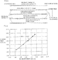
Fig. 4 . In the expression (y = 1.1553 x -0.2667) shown inFig. 4 , x denotes the 30-minute rest OCV, and y denotes the two-hour rest OCV (the true open-circuit voltage before correction). InFig. 4 , each OCV is indicated as the OCV of an electric cell, as is clear from the numerical values on the axis of ordinates and the axis of abscissas. - A further correction is made on the basis of the temperature T[°C] and the discharge current Id[A] upon the completion of the discharge to determine the true open-circuit voltage value of the block. As illustrated in
Fig. 5 and Fig. 6 , the correction can be made on the basis of the point that the value of (the two-hour rest OCV - the 30-minute rest OCV)[V] and the temperature T[°C] and the discharge current [A] have a predetermined relationship. The value of (the two-hour rest OCV - the 30-minute rest OCV)[V] is a correction value (a value to be corrected), and the value to be corrected is the two-hour rest OCV (before correction) [V] determined on the basis of the 30-minute rest OCV. - In the expression (y = -0.000334 x +0.126763) shown in
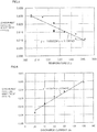
Fig. 5 , x denotes temperature and y denotes (the two-hour rest OCV - the 30-minute rest OCV). According toFig. 5 , if the temperature rises by, for example, 10°C, then a correction of approximately -0.004V (-4mV) is required. - In the expression (y = 0.000174 x +0.004195) shown in
Fig. 6 , x denotes discharge current and y denotes (the two-hour rest OCV - the 30minute rest OCV). According toFig. 6 , if the discharge current increases by, for example, 10A, then a correction of approximately +0.003V (3mV) is required. - For each
module 34, the voltages of theblocks 33 constituting themodule 34 are determined to identify theblock 33 having a highest voltage [V]. Then, based on the (highest) voltage of theblock 33 determined in each of themodules 34, the comparison among themodules 34 is carried out to determine the voltage of theblock 33 in themodule 34 having (for example) a fifth highest voltage. - Subsequently, the determined voltage [V] is converted into the depth of charge [Ah]. The voltage is based on a voltage measured in the single-phase region, so that the voltage [V] can be converted into the depth of charge [Ah] (refer to
Fig. 2 ). The depth of charge (capacity) is based on the voltage of theblock 33 and therefore equivalent to the capacity of asingle string 32. Thus, multiplying the depth of charge by twelve, which is the number of thestrings 32, determines the depth of charge [Ah] of the block, which is a normal block depth of charge Qn [Ah]. - The current residual capacity Qsc in expression (3) is determined according to expression (5) given below:

- In
Fig. 7 described above, if the current equivalent cycle (Cec) is set, the current block residual capacity (Qsc) may be determined. As described above, the residual capacity inFig. 7 is the residual capacity of an electric cell. - The method for calculating the state of charge of a sodium-sulfur battery according to the present invention may be preferable used as a means for accurately and precisely calculating the current state of charge of a sodium-sulfur battery used for applications, such as load leveling, measures against a momentary drop in power, or compensation for fluctuations in the power generated by a natural energy generating system.
- 3: sodium-sulfur battery; 31: electric cell; 32: string; 33: block; and 34: module
Claims (3)
- A method for operating a sodium-sulfur (3) battery constituted by forming a string (32) by connecting an s number of plural electric cells (31) in series, connecting a u number of plural strings (32) in parallel to form a block (33), connecting an n number of plural blocks (33) in series to form a module (34), and then connecting an m number of plural modules (34) in series,
the method including calculating a state of charge Qr of the sodium-sulfur battery by determining the used capacity Qu of the sodium-sulfur battery, determining the product capacity Qa, i.e. absolute capacity, of the sodium-sulfur battery and determining the residual capacity in the final year Qsf of the sodium-sulfur battery, and applying expression (1) to calculate the state of charge Qr of the sodium-sulfur battery: Qu: used capacityQa: product capacityQsf: residual capacity in the final yearwhere fl(Cef): conversion function for determining a residual capacity Qsf in the final year on the basis of the equivalent cycle Cef in the final year;
where an equivalent cycle corresponds, for a rated capacity, to a cycle of discharge followed by a charge; and
where the final year corresponds to the final year in the expected life of the sodium-sulfur battery. - The method according to claim 1, wherein the battery is operated in order to complete a charge and in order to complete a discharge, wherein, in the calculation of the state of charge Qr of the sodium-sulfur battery, the used capacity Qu is reset to 0 [Ah] at the end of a charge and also reset according to expression (3) given below in a single-phase region after completion of the discharge:
 Qn: normal block depth of chargeQsc : current block residual capacitywhere f2(Vi(t, T, Id)): conversion function for determining a depth of charge of a block (33) based on a voltage of a block of modules (34) of an i-th highest voltage after having compared blocks (33) each showing the highest voltage in each of modules (34) (the voltage is to be obtained by converting into a stable open-circuit voltage on the basis of an unstable open-circuit voltage measured after t time has passed since completion of a discharge in a single-phase region and then correcting the converted stable open-circuit voltage on the basis of a temperature T upon completion of the discharge and a discharge current Id upon completion of the discharge):

- The method according to claim 1 or 2, wherein the sodium-sulfur battery, the state of charge of which is to be calculated is a sodium-sulfur battery which constitutes a power storage compensating unit in an interconnected system, which combines a power generating unit incurring output fluctuations and the power storage compensating unit to supply power to a power system, and which compensates for output fluctuations of the power generating unit.
Applications Claiming Priority (2)
| Application Number | Priority Date | Filing Date | Title |
|---|---|---|---|
| JP2009073877 | 2009-03-25 | ||
| PCT/JP2010/052203 WO2010109977A1 (en) | 2009-03-25 | 2010-02-15 | Method for calculating residual capacity of sodium-sulfur battery |
Publications (3)
| Publication Number | Publication Date |
|---|---|
| EP2413151A1 EP2413151A1 (en) | 2012-02-01 |
| EP2413151A4 EP2413151A4 (en) | 2016-10-05 |
| EP2413151B1 true EP2413151B1 (en) | 2018-06-20 |
Family
ID=42780673
Family Applications (1)
| Application Number | Title | Priority Date | Filing Date |
|---|---|---|---|
| EP10755778.7A Active EP2413151B1 (en) | 2009-03-25 | 2010-02-15 | Method for calculating the state of charge of a sodium-sulfur battery |
Country Status (5)
| Country | Link |
|---|---|
| US (1) | US8957640B2 (en) |
| EP (1) | EP2413151B1 (en) |
| JP (1) | JP5483748B2 (en) |
| CN (1) | CN102301251B (en) |
| WO (1) | WO2010109977A1 (en) |
Families Citing this family (7)
| Publication number | Priority date | Publication date | Assignee | Title |
|---|---|---|---|---|
| US9128159B2 (en) * | 2012-12-12 | 2015-09-08 | GM Global Technology Operations LLC | Plug-in charge capacity estimation method for lithium iron-phosphate batteries |
| CN106443495B (en) * | 2016-12-07 | 2019-03-26 | 上海电气钠硫储能技术有限公司 | A kind of energy type sodium-sulphur battery life detecting method |
| CN110018422B (en) * | 2018-01-05 | 2021-10-19 | 宁德新能源科技有限公司 | Battery management method and device |
| CN108279385A (en) * | 2018-01-26 | 2018-07-13 | 深圳市道通智能航空技术有限公司 | State of charge evaluation method, device and the electronic equipment of battery |
| KR102002859B1 (en) * | 2018-03-26 | 2019-07-23 | 숭실대학교산학협력단 | Charger with battery diagnosis and control method thereof |
| PL3674730T3 (en) * | 2018-04-10 | 2021-08-16 | Lg Chem, Ltd. | Battery diagnostic device and method |
| EP3869607A4 (en) | 2018-10-18 | 2022-08-31 | NGK Insulators, Ltd. | Power storage battery control device and power storage battery control method |
Family Cites Families (11)
| Publication number | Priority date | Publication date | Assignee | Title |
|---|---|---|---|---|
| JP2597208B2 (en) * | 1989-11-15 | 1997-04-02 | 株式会社日立製作所 | Method for estimating remaining capacity of sodium-sulfur battery |
| JP2937796B2 (en) | 1994-04-27 | 1999-08-23 | 日本碍子株式会社 | Method for measuring charge / discharge current of secondary battery for power storage, method for measuring remaining power, and measuring device |
| JP3467969B2 (en) * | 1996-05-30 | 2003-11-17 | 株式会社日本自動車部品総合研究所 | Battery fuel gauge |
| JP2000048865A (en) * | 1998-07-31 | 2000-02-18 | Hitachi Ltd | Battery system |
| JP3505116B2 (en) | 1999-11-04 | 2004-03-08 | 日本碍子株式会社 | Method of charging sodium-sulfur battery |
| JP3505124B2 (en) * | 2000-03-28 | 2004-03-08 | 東京電力株式会社 | Emergency power supply system and system for automatically detecting the presence or absence of failure of a single cell in a battery used in the system |
| JP2003194897A (en) | 2001-12-26 | 2003-07-09 | Sanyo Electric Co Ltd | Battery residual capacity operating method and pack battery |
| JP5201863B2 (en) * | 2007-03-29 | 2013-06-05 | 日本碍子株式会社 | Control method of sodium-sulfur battery |
| JP2009236800A (en) * | 2008-03-28 | 2009-10-15 | Mitsubishi Motors Corp | Remaining battery capacity display method and remaining battery capacity display device |
| CN102138247B (en) * | 2008-09-30 | 2014-03-12 | 日本碍子株式会社 | Method for controlling sodium-sulfur battery |
| JP5453288B2 (en) * | 2008-09-30 | 2014-03-26 | 日本碍子株式会社 | Control method of sodium-sulfur battery |
-
2010
- 2010-02-15 CN CN201080006258.2A patent/CN102301251B/en active Active
- 2010-02-15 WO PCT/JP2010/052203 patent/WO2010109977A1/en active Application Filing
- 2010-02-15 JP JP2011505929A patent/JP5483748B2/en active Active
- 2010-02-15 EP EP10755778.7A patent/EP2413151B1/en active Active
-
2011
- 2011-08-31 US US13/222,009 patent/US8957640B2/en active Active
Non-Patent Citations (1)
| Title |
|---|
| None * |
Also Published As
| Publication number | Publication date |
|---|---|
| JPWO2010109977A1 (en) | 2012-09-27 |
| CN102301251B (en) | 2015-01-21 |
| JP5483748B2 (en) | 2014-05-07 |
| WO2010109977A1 (en) | 2010-09-30 |
| US20110313699A1 (en) | 2011-12-22 |
| EP2413151A4 (en) | 2016-10-05 |
| CN102301251A (en) | 2011-12-28 |
| US8957640B2 (en) | 2015-02-17 |
| EP2413151A1 (en) | 2012-02-01 |
Similar Documents
| Publication | Publication Date | Title |
|---|---|---|
| EP2413151B1 (en) | Method for calculating the state of charge of a sodium-sulfur battery | |
| EP2395595B1 (en) | Method for determining drop in capacity of sodium-sulfur battery | |
| US11515713B2 (en) | Monitoring and balancing capacity in lithium sulfur cells arranged in series | |
| EP2434573B1 (en) | Method for calculating number of healthy strings of sodium-sulfur battery and failure detection method using same | |
| US7459884B2 (en) | Remaining capacity calculation method for secondary battery, and battery pack | |
| US8264202B2 (en) | Method and apparatus for determining state of charge of a battery using an open-circuit voltage | |
| KR101238478B1 (en) | The Measurment Method of Battery SOC | |
| US8823326B2 (en) | Method for determining the state of charge of a battery in charging or discharging phase | |
| JP2015511309A (en) | Method and apparatus for determining state of charge of electrical energy storage | |
| JPWO2012053075A1 (en) | Method and apparatus for detecting state of power storage device | |
| CN111175664A (en) | Method for determining aging state of battery, controller and vehicle | |
| US20190020045A1 (en) | Redox flow battery and method of measuring state of charge thereof | |
| JP3505111B2 (en) | Operation method of sodium-sulfur battery | |
| CN109444750A (en) | A kind of capacity of lead acid battery predictor method | |
| JP5201863B2 (en) | Control method of sodium-sulfur battery | |
| KR102309014B1 (en) | Intelligent apparatus and method of battery charge/discharge using charging profile | |
| US20220352736A1 (en) | Charging/discharging control device and charging/discharging control method | |
| KR20230139969A (en) | A method of measuring battery entrophy and battery deterioration estimation method by using the same | |
| Matsushima et al. | Residual capacity estimation of stationary lithium-ion secondary cells in telecommunications systems using a brief discharge |
Legal Events
| Date | Code | Title | Description |
|---|---|---|---|
| PUAI | Public reference made under article 153(3) epc to a published international application that has entered the european phase |
Free format text: ORIGINAL CODE: 0009012 |
|
| 17P | Request for examination filed |
Effective date: 20110920 |
|
| AK | Designated contracting states |
Kind code of ref document: A1 Designated state(s): AT BE BG CH CY CZ DE DK EE ES FI FR GB GR HR HU IE IS IT LI LT LU LV MC MK MT NL NO PL PT RO SE SI SK SM TR |
|
| DAX | Request for extension of the european patent (deleted) | ||
| RA4 | Supplementary search report drawn up and despatched (corrected) |
Effective date: 20160905 |
|
| RIC1 | Information provided on ipc code assigned before grant |
Ipc: G01R 31/36 20060101AFI20160830BHEP Ipc: H01M 10/39 20060101ALI20160830BHEP |
|
| GRAP | Despatch of communication of intention to grant a patent |
Free format text: ORIGINAL CODE: EPIDOSNIGR1 |
|
| STAA | Information on the status of an ep patent application or granted ep patent |
Free format text: STATUS: GRANT OF PATENT IS INTENDED |
|
| INTG | Intention to grant announced |
Effective date: 20171213 |
|
| GRAS | Grant fee paid |
Free format text: ORIGINAL CODE: EPIDOSNIGR3 |
|
| GRAJ | Information related to disapproval of communication of intention to grant by the applicant or resumption of examination proceedings by the epo deleted |
Free format text: ORIGINAL CODE: EPIDOSDIGR1 |
|
| GRAL | Information related to payment of fee for publishing/printing deleted |
Free format text: ORIGINAL CODE: EPIDOSDIGR3 |
|
| STAA | Information on the status of an ep patent application or granted ep patent |
Free format text: STATUS: REQUEST FOR EXAMINATION WAS MADE |
|
| GRAR | Information related to intention to grant a patent recorded |
Free format text: ORIGINAL CODE: EPIDOSNIGR71 |
|
| STAA | Information on the status of an ep patent application or granted ep patent |
Free format text: STATUS: GRANT OF PATENT IS INTENDED |
|
| GRAA | (expected) grant |
Free format text: ORIGINAL CODE: 0009210 |
|
| STAA | Information on the status of an ep patent application or granted ep patent |
Free format text: STATUS: THE PATENT HAS BEEN GRANTED |
|
| INTC | Intention to grant announced (deleted) | ||
| AK | Designated contracting states |
Kind code of ref document: B1 Designated state(s): AT BE BG CH CY CZ DE DK EE ES FI FR GB GR HR HU IE IS IT LI LT LU LV MC MK MT NL NO PL PT RO SE SI SK SM TR |
|
| INTG | Intention to grant announced |
Effective date: 20180514 |
|
| REG | Reference to a national code |
Ref country code: GB Ref legal event code: FG4D |
|
| REG | Reference to a national code |
Ref country code: IE Ref legal event code: FG4D |
|
| REG | Reference to a national code |
Ref country code: AT Ref legal event code: REF Ref document number: 1010989 Country of ref document: AT Kind code of ref document: T Effective date: 20180715 |
|
| REG | Reference to a national code |
Ref country code: DE Ref legal event code: R096 Ref document number: 602010051404 Country of ref document: DE |
|
| REG | Reference to a national code |
Ref country code: NL Ref legal event code: MP Effective date: 20180620 |
|
| PG25 | Lapsed in a contracting state [announced via postgrant information from national office to epo] |
Ref country code: SE Free format text: LAPSE BECAUSE OF FAILURE TO SUBMIT A TRANSLATION OF THE DESCRIPTION OR TO PAY THE FEE WITHIN THE PRESCRIBED TIME-LIMIT Effective date: 20180620 Ref country code: BG Free format text: LAPSE BECAUSE OF FAILURE TO SUBMIT A TRANSLATION OF THE DESCRIPTION OR TO PAY THE FEE WITHIN THE PRESCRIBED TIME-LIMIT Effective date: 20180920 Ref country code: FI Free format text: LAPSE BECAUSE OF FAILURE TO SUBMIT A TRANSLATION OF THE DESCRIPTION OR TO PAY THE FEE WITHIN THE PRESCRIBED TIME-LIMIT Effective date: 20180620 Ref country code: NO Free format text: LAPSE BECAUSE OF FAILURE TO SUBMIT A TRANSLATION OF THE DESCRIPTION OR TO PAY THE FEE WITHIN THE PRESCRIBED TIME-LIMIT Effective date: 20180920 Ref country code: LT Free format text: LAPSE BECAUSE OF FAILURE TO SUBMIT A TRANSLATION OF THE DESCRIPTION OR TO PAY THE FEE WITHIN THE PRESCRIBED TIME-LIMIT Effective date: 20180620 |
|
| REG | Reference to a national code |
Ref country code: LT Ref legal event code: MG4D |
|
| PG25 | Lapsed in a contracting state [announced via postgrant information from national office to epo] |
Ref country code: GR Free format text: LAPSE BECAUSE OF FAILURE TO SUBMIT A TRANSLATION OF THE DESCRIPTION OR TO PAY THE FEE WITHIN THE PRESCRIBED TIME-LIMIT Effective date: 20180921 Ref country code: HR Free format text: LAPSE BECAUSE OF FAILURE TO SUBMIT A TRANSLATION OF THE DESCRIPTION OR TO PAY THE FEE WITHIN THE PRESCRIBED TIME-LIMIT Effective date: 20180620 Ref country code: LV Free format text: LAPSE BECAUSE OF FAILURE TO SUBMIT A TRANSLATION OF THE DESCRIPTION OR TO PAY THE FEE WITHIN THE PRESCRIBED TIME-LIMIT Effective date: 20180620 |
|
| REG | Reference to a national code |
Ref country code: AT Ref legal event code: MK05 Ref document number: 1010989 Country of ref document: AT Kind code of ref document: T Effective date: 20180620 |
|
| PG25 | Lapsed in a contracting state [announced via postgrant information from national office to epo] |
Ref country code: NL Free format text: LAPSE BECAUSE OF FAILURE TO SUBMIT A TRANSLATION OF THE DESCRIPTION OR TO PAY THE FEE WITHIN THE PRESCRIBED TIME-LIMIT Effective date: 20180620 |
|
| PG25 | Lapsed in a contracting state [announced via postgrant information from national office to epo] |
Ref country code: RO Free format text: LAPSE BECAUSE OF FAILURE TO SUBMIT A TRANSLATION OF THE DESCRIPTION OR TO PAY THE FEE WITHIN THE PRESCRIBED TIME-LIMIT Effective date: 20180620 Ref country code: CZ Free format text: LAPSE BECAUSE OF FAILURE TO SUBMIT A TRANSLATION OF THE DESCRIPTION OR TO PAY THE FEE WITHIN THE PRESCRIBED TIME-LIMIT Effective date: 20180620 Ref country code: PL Free format text: LAPSE BECAUSE OF FAILURE TO SUBMIT A TRANSLATION OF THE DESCRIPTION OR TO PAY THE FEE WITHIN THE PRESCRIBED TIME-LIMIT Effective date: 20180620 Ref country code: IS Free format text: LAPSE BECAUSE OF FAILURE TO SUBMIT A TRANSLATION OF THE DESCRIPTION OR TO PAY THE FEE WITHIN THE PRESCRIBED TIME-LIMIT Effective date: 20181020 Ref country code: AT Free format text: LAPSE BECAUSE OF FAILURE TO SUBMIT A TRANSLATION OF THE DESCRIPTION OR TO PAY THE FEE WITHIN THE PRESCRIBED TIME-LIMIT Effective date: 20180620 Ref country code: EE Free format text: LAPSE BECAUSE OF FAILURE TO SUBMIT A TRANSLATION OF THE DESCRIPTION OR TO PAY THE FEE WITHIN THE PRESCRIBED TIME-LIMIT Effective date: 20180620 Ref country code: SK Free format text: LAPSE BECAUSE OF FAILURE TO SUBMIT A TRANSLATION OF THE DESCRIPTION OR TO PAY THE FEE WITHIN THE PRESCRIBED TIME-LIMIT Effective date: 20180620 |
|
| PG25 | Lapsed in a contracting state [announced via postgrant information from national office to epo] |
Ref country code: ES Free format text: LAPSE BECAUSE OF FAILURE TO SUBMIT A TRANSLATION OF THE DESCRIPTION OR TO PAY THE FEE WITHIN THE PRESCRIBED TIME-LIMIT Effective date: 20180620 Ref country code: IT Free format text: LAPSE BECAUSE OF FAILURE TO SUBMIT A TRANSLATION OF THE DESCRIPTION OR TO PAY THE FEE WITHIN THE PRESCRIBED TIME-LIMIT Effective date: 20180620 Ref country code: SM Free format text: LAPSE BECAUSE OF FAILURE TO SUBMIT A TRANSLATION OF THE DESCRIPTION OR TO PAY THE FEE WITHIN THE PRESCRIBED TIME-LIMIT Effective date: 20180620 |
|
| REG | Reference to a national code |
Ref country code: DE Ref legal event code: R097 Ref document number: 602010051404 Country of ref document: DE |
|
| PLBE | No opposition filed within time limit |
Free format text: ORIGINAL CODE: 0009261 |
|
| STAA | Information on the status of an ep patent application or granted ep patent |
Free format text: STATUS: NO OPPOSITION FILED WITHIN TIME LIMIT |
|
| 26N | No opposition filed |
Effective date: 20190321 |
|
| PG25 | Lapsed in a contracting state [announced via postgrant information from national office to epo] |
Ref country code: DK Free format text: LAPSE BECAUSE OF FAILURE TO SUBMIT A TRANSLATION OF THE DESCRIPTION OR TO PAY THE FEE WITHIN THE PRESCRIBED TIME-LIMIT Effective date: 20180620 |
|
| PG25 | Lapsed in a contracting state [announced via postgrant information from national office to epo] |
Ref country code: SI Free format text: LAPSE BECAUSE OF FAILURE TO SUBMIT A TRANSLATION OF THE DESCRIPTION OR TO PAY THE FEE WITHIN THE PRESCRIBED TIME-LIMIT Effective date: 20180620 |
|
| REG | Reference to a national code |
Ref country code: CH Ref legal event code: PL |
|
| PG25 | Lapsed in a contracting state [announced via postgrant information from national office to epo] |
Ref country code: LU Free format text: LAPSE BECAUSE OF NON-PAYMENT OF DUE FEES Effective date: 20190215 Ref country code: MC Free format text: LAPSE BECAUSE OF FAILURE TO SUBMIT A TRANSLATION OF THE DESCRIPTION OR TO PAY THE FEE WITHIN THE PRESCRIBED TIME-LIMIT Effective date: 20180620 |
|
| REG | Reference to a national code |
Ref country code: BE Ref legal event code: MM Effective date: 20190228 |
|
| REG | Reference to a national code |
Ref country code: IE Ref legal event code: MM4A |
|
| PG25 | Lapsed in a contracting state [announced via postgrant information from national office to epo] |
Ref country code: LI Free format text: LAPSE BECAUSE OF NON-PAYMENT OF DUE FEES Effective date: 20190228 Ref country code: CH Free format text: LAPSE BECAUSE OF NON-PAYMENT OF DUE FEES Effective date: 20190228 |
|
| PG25 | Lapsed in a contracting state [announced via postgrant information from national office to epo] |
Ref country code: IE Free format text: LAPSE BECAUSE OF NON-PAYMENT OF DUE FEES Effective date: 20190215 |
|
| PG25 | Lapsed in a contracting state [announced via postgrant information from national office to epo] |
Ref country code: FR Free format text: LAPSE BECAUSE OF NON-PAYMENT OF DUE FEES Effective date: 20190228 Ref country code: BE Free format text: LAPSE BECAUSE OF NON-PAYMENT OF DUE FEES Effective date: 20190228 |
|
| PG25 | Lapsed in a contracting state [announced via postgrant information from national office to epo] |
Ref country code: TR Free format text: LAPSE BECAUSE OF FAILURE TO SUBMIT A TRANSLATION OF THE DESCRIPTION OR TO PAY THE FEE WITHIN THE PRESCRIBED TIME-LIMIT Effective date: 20180620 |
|
| PG25 | Lapsed in a contracting state [announced via postgrant information from national office to epo] |
Ref country code: MT Free format text: LAPSE BECAUSE OF NON-PAYMENT OF DUE FEES Effective date: 20190215 Ref country code: PT Free format text: LAPSE BECAUSE OF FAILURE TO SUBMIT A TRANSLATION OF THE DESCRIPTION OR TO PAY THE FEE WITHIN THE PRESCRIBED TIME-LIMIT Effective date: 20181022 |
|
| PG25 | Lapsed in a contracting state [announced via postgrant information from national office to epo] |
Ref country code: CY Free format text: LAPSE BECAUSE OF FAILURE TO SUBMIT A TRANSLATION OF THE DESCRIPTION OR TO PAY THE FEE WITHIN THE PRESCRIBED TIME-LIMIT Effective date: 20180620 |
|
| PG25 | Lapsed in a contracting state [announced via postgrant information from national office to epo] |
Ref country code: HU Free format text: LAPSE BECAUSE OF FAILURE TO SUBMIT A TRANSLATION OF THE DESCRIPTION OR TO PAY THE FEE WITHIN THE PRESCRIBED TIME-LIMIT; INVALID AB INITIO Effective date: 20100215 |
|
| PG25 | Lapsed in a contracting state [announced via postgrant information from national office to epo] |
Ref country code: MK Free format text: LAPSE BECAUSE OF FAILURE TO SUBMIT A TRANSLATION OF THE DESCRIPTION OR TO PAY THE FEE WITHIN THE PRESCRIBED TIME-LIMIT Effective date: 20180620 |
|
| PGFP | Annual fee paid to national office [announced via postgrant information from national office to epo] |
Ref country code: GB Payment date: 20221230 Year of fee payment: 14 |
|
| PGFP | Annual fee paid to national office [announced via postgrant information from national office to epo] |
Ref country code: DE Payment date: 20221229 Year of fee payment: 14 |