EP2412926A2 - Hollow blade for a gas turbine - Google Patents
Hollow blade for a gas turbine Download PDFInfo
- Publication number
- EP2412926A2 EP2412926A2 EP11173975A EP11173975A EP2412926A2 EP 2412926 A2 EP2412926 A2 EP 2412926A2 EP 11173975 A EP11173975 A EP 11173975A EP 11173975 A EP11173975 A EP 11173975A EP 2412926 A2 EP2412926 A2 EP 2412926A2
- Authority
- EP
- European Patent Office
- Prior art keywords
- section
- airfoil
- recited
- cavity
- rotor blade
- Prior art date
- Legal status (The legal status is an assumption and is not a legal conclusion. Google has not performed a legal analysis and makes no representation as to the accuracy of the status listed.)
- Granted
Links
- 238000000034 method Methods 0.000 claims description 6
- 238000004519 manufacturing process Methods 0.000 claims description 4
- 239000000463 material Substances 0.000 claims description 3
- 239000007787 solid Substances 0.000 claims description 3
- 230000007423 decrease Effects 0.000 claims 1
- 239000007789 gas Substances 0.000 description 11
- 230000008901 benefit Effects 0.000 description 5
- 238000005219 brazing Methods 0.000 description 2
- 230000004048 modification Effects 0.000 description 2
- 238000012986 modification Methods 0.000 description 2
- 238000003466 welding Methods 0.000 description 2
- 230000000712 assembly Effects 0.000 description 1
- 238000000429 assembly Methods 0.000 description 1
- 238000005266 casting Methods 0.000 description 1
- 238000002485 combustion reaction Methods 0.000 description 1
- 238000001816 cooling Methods 0.000 description 1
- 238000010248 power generation Methods 0.000 description 1
- 230000008569 process Effects 0.000 description 1
- 230000009467 reduction Effects 0.000 description 1
- 230000004044 response Effects 0.000 description 1
Images



Classifications
-
- F—MECHANICAL ENGINEERING; LIGHTING; HEATING; WEAPONS; BLASTING
- F01—MACHINES OR ENGINES IN GENERAL; ENGINE PLANTS IN GENERAL; STEAM ENGINES
- F01D—NON-POSITIVE DISPLACEMENT MACHINES OR ENGINES, e.g. STEAM TURBINES
- F01D5/00—Blades; Blade-carrying members; Heating, heat-insulating, cooling or antivibration means on the blades or the members
- F01D5/12—Blades
- F01D5/14—Form or construction
- F01D5/147—Construction, i.e. structural features, e.g. of weight-saving hollow blades
-
- F—MECHANICAL ENGINEERING; LIGHTING; HEATING; WEAPONS; BLASTING
- F01—MACHINES OR ENGINES IN GENERAL; ENGINE PLANTS IN GENERAL; STEAM ENGINES
- F01D—NON-POSITIVE DISPLACEMENT MACHINES OR ENGINES, e.g. STEAM TURBINES
- F01D5/00—Blades; Blade-carrying members; Heating, heat-insulating, cooling or antivibration means on the blades or the members
- F01D5/12—Blades
- F01D5/14—Form or construction
- F01D5/18—Hollow blades, i.e. blades with cooling or heating channels or cavities; Heating, heat-insulating or cooling means on blades
-
- F—MECHANICAL ENGINEERING; LIGHTING; HEATING; WEAPONS; BLASTING
- F01—MACHINES OR ENGINES IN GENERAL; ENGINE PLANTS IN GENERAL; STEAM ENGINES
- F01D—NON-POSITIVE DISPLACEMENT MACHINES OR ENGINES, e.g. STEAM TURBINES
- F01D5/00—Blades; Blade-carrying members; Heating, heat-insulating, cooling or antivibration means on the blades or the members
- F01D5/12—Blades
- F01D5/22—Blade-to-blade connections, e.g. for damping vibrations
- F01D5/225—Blade-to-blade connections, e.g. for damping vibrations by shrouding
-
- F—MECHANICAL ENGINEERING; LIGHTING; HEATING; WEAPONS; BLASTING
- F01—MACHINES OR ENGINES IN GENERAL; ENGINE PLANTS IN GENERAL; STEAM ENGINES
- F01D—NON-POSITIVE DISPLACEMENT MACHINES OR ENGINES, e.g. STEAM TURBINES
- F01D5/00—Blades; Blade-carrying members; Heating, heat-insulating, cooling or antivibration means on the blades or the members
- F01D5/30—Fixing blades to rotors; Blade roots ; Blade spacers
-
- F—MECHANICAL ENGINEERING; LIGHTING; HEATING; WEAPONS; BLASTING
- F05—INDEXING SCHEMES RELATING TO ENGINES OR PUMPS IN VARIOUS SUBCLASSES OF CLASSES F01-F04
- F05D—INDEXING SCHEME FOR ASPECTS RELATING TO NON-POSITIVE-DISPLACEMENT MACHINES OR ENGINES, GAS-TURBINES OR JET-PROPULSION PLANTS
- F05D2220/00—Application
- F05D2220/30—Application in turbines
- F05D2220/32—Application in turbines in gas turbines
- F05D2220/321—Application in turbines in gas turbines for a special turbine stage
-
- Y—GENERAL TAGGING OF NEW TECHNOLOGICAL DEVELOPMENTS; GENERAL TAGGING OF CROSS-SECTIONAL TECHNOLOGIES SPANNING OVER SEVERAL SECTIONS OF THE IPC; TECHNICAL SUBJECTS COVERED BY FORMER USPC CROSS-REFERENCE ART COLLECTIONS [XRACs] AND DIGESTS
- Y02—TECHNOLOGIES OR APPLICATIONS FOR MITIGATION OR ADAPTATION AGAINST CLIMATE CHANGE
- Y02T—CLIMATE CHANGE MITIGATION TECHNOLOGIES RELATED TO TRANSPORTATION
- Y02T50/00—Aeronautics or air transport
- Y02T50/60—Efficient propulsion technologies, e.g. for aircraft
-
- Y—GENERAL TAGGING OF NEW TECHNOLOGICAL DEVELOPMENTS; GENERAL TAGGING OF CROSS-SECTIONAL TECHNOLOGIES SPANNING OVER SEVERAL SECTIONS OF THE IPC; TECHNICAL SUBJECTS COVERED BY FORMER USPC CROSS-REFERENCE ART COLLECTIONS [XRACs] AND DIGESTS
- Y10—TECHNICAL SUBJECTS COVERED BY FORMER USPC
- Y10T—TECHNICAL SUBJECTS COVERED BY FORMER US CLASSIFICATION
- Y10T29/00—Metal working
- Y10T29/49—Method of mechanical manufacture
- Y10T29/49316—Impeller making
- Y10T29/49318—Repairing or disassembling
-
- Y—GENERAL TAGGING OF NEW TECHNOLOGICAL DEVELOPMENTS; GENERAL TAGGING OF CROSS-SECTIONAL TECHNOLOGIES SPANNING OVER SEVERAL SECTIONS OF THE IPC; TECHNICAL SUBJECTS COVERED BY FORMER USPC CROSS-REFERENCE ART COLLECTIONS [XRACs] AND DIGESTS
- Y10—TECHNICAL SUBJECTS COVERED BY FORMER USPC
- Y10T—TECHNICAL SUBJECTS COVERED BY FORMER US CLASSIFICATION
- Y10T29/00—Metal working
- Y10T29/49—Method of mechanical manufacture
- Y10T29/49316—Impeller making
- Y10T29/49336—Blade making
Definitions
- the present disclosure relates to a gas turbine engine, and more particularly to a turbine blade thereof.
- Gas turbine engines often include a multiple of rotor assemblies within a fan, compressor and turbine section.
- Each rotor assembly has a multitude of blades attached about a circumference of a rotor disk.
- Each blade includes a root section that attaches to the rotor disk, a platform section, and an airfoil section that extends radially outwardly from the platform section.
- a rotor blade for a turbine engine includes an airfoil section which extends from a platform section opposite a root section, the airfoil section defines a cavity which extends from an airfoil tip section toward a root section.
- a method of forming a rotor blade according to an exemplary aspect of the present disclosure includes defining a cavity which extends from an airfoil tip section toward a root section of an airfoil section of a turbine blade.
- Figure 1 schematically illustrates a gas turbine engine 20 which generally includes a fan section F, a compressor section C, a combustor section G, a turbine section T, an augmentor section A, and an exhaust duct assembly E.
- the compressor section C, combustor section G, and turbine section T are generally referred to as the core engine.
- An engine longitudinal axis X is centrally disposed and extends longitudinally through these sections. While a particular gas turbine engine is schematically illustrated in the disclosed non-limiting embodiment, it should be understood that the disclosure is applicable to other gas turbine engine configurations, including, for example, gas turbines for power generation, turbojet engines, high bypass turbofan engines, low bypass turbofan engines, turboshaft engines, etc.
- engine components may be internally cooled or uncooled dependant on the temperatures of the hot combustion core gases.
- a High Pressure Turbine (HPT) of the turbine section T may be cooled, while a Low Pressure Turbine (LPT) may be uncooled.
- HPT High Pressure Turbine
- LPT Low Pressure Turbine
- the uncooled Low Pressure Turbine (LPT) section of the gas turbine engine 20 includes a rotor assembly 22 along the engine longitudinal axis X.
- the rotor assembly 22 includes a plurality of blades 24 circumferentially disposed around a respective rotor disk 26. It should be understood that a multiple of discs may be contained within each engine section and that although the LPT section is illustrated and described in the disclosed embodiment, other sections will also benefit herefrom.
- each blade 24 generally includes a root section 30, a platform section 32, and an airfoil section 34 along a longitudinal axis B.
- the outer edge of each airfoil section 34 is an airfoil tip section 34T which is adjacent the blade outer air seal assembly (not shown).
- the airfoil section 34 defines a suction side 34S and a pressure side 34P ( Figure 3 ).
- the blade 24 is hollowed to define a cavity 34C, by casting or other conventional process, from the airfoil tip section 34T toward the root section 30.
- the cavity 34C extends towards the root section 30 from the airfoil tip section 34T but not through the root section 30.
- the cavity 34C may be filled with various honeycomb, rib or fin structure. Alternatively, or in addition, the cavity 34C may filled with a gas or contain a vacuum.
- Wall thickness at each section may be determined, for example, by minimum material manufacturing limits or maximum stress allowable limits, generally whichever is less. This maintains a high stiffness to weight ratio of the airfoil for better vibration response while maintaining a nearly constant mean stress along the span.
- the blade 24 may have a zero, positive ( Figure 3 ) or negative ( Figure 4 ) taper ratio such that the taper can be optimized for maximum efficiency. It should be understood that a positive taper ratio defines a longer chord at the airfoil tip section 34T that at the root section 30. A longer chord at the airfoil tip section 34T reduces loading with a reduced airfoil thickness at the root section 30 to minimize blockage for an overall efficiency gain.
- the airfoil tip section 34T receives a tip shroud 40 to close the cavity 34C.
- the tip shroud 40 may be attached in various manners through welding, brazing, bonding or other such permanent attachment.
- the tip shroud 40 includes rails 42 which define knife edge seals with stationary engine structure (not shown).
- the rails 42 define full annular knife seals when assembled to the rotor disk 22. That is, the rails 42 on one blade 24 interface with the rails 42 on an adjacent blade 24 to form a full turbine ring tip shroud.
- the airfoil tip section 34T may alternatively be formed with an integral tip shroud 44 with rails which receives a separate cover plate 50 to close the cavity 34C. That is, the cover plate 50 is sized to plug the cavity 34C and may be generally airfoil shaped. The cover plate 50 may be attached in various manners through welding, brazing, bonding or other such permanent attachment.
- airfoils that are hollowed from the airfoil tip section 34T toward the root section 30 facilitate a solid attachment to the rotor disk 22.
- a solid root section 30 provides for reduced circumferential thickness requirements and reduced potential of pitch limitations on the number of airfoils that will fit around the circumference of the rotor disk 22.
Landscapes
- Engineering & Computer Science (AREA)
- Mechanical Engineering (AREA)
- General Engineering & Computer Science (AREA)
- Architecture (AREA)
- Structures Of Non-Positive Displacement Pumps (AREA)
- Turbine Rotor Nozzle Sealing (AREA)
Abstract
Description
- The present disclosure relates to a gas turbine engine, and more particularly to a turbine blade thereof.
- Gas turbine engines often include a multiple of rotor assemblies within a fan, compressor and turbine section. Each rotor assembly has a multitude of blades attached about a circumference of a rotor disk. Each blade includes a root section that attaches to the rotor disk, a platform section, and an airfoil section that extends radially outwardly from the platform section.
- When engine weight becomes a concern, emphasis is directed toward the reduction of blade weight since every one pound of weight in the set of blades is worth about three pounds of weight in the rotor disk due to centrifugal forces. Weight is typically removed from the blade by thinning airfoil walls and ribs until a minimum thickness is achieved from a manufacturing and structural standpoint.
- A rotor blade for a turbine engine according to an exemplary aspect of the present disclosure includes an airfoil section which extends from a platform section opposite a root section, the airfoil section defines a cavity which extends from an airfoil tip section toward a root section.
- A method of forming a rotor blade according to an exemplary aspect of the present disclosure includes defining a cavity which extends from an airfoil tip section toward a root section of an airfoil section of a turbine blade.
- The various features and advantages of this disclosure will become apparent to those skilled in the art from the following detailed description of the disclosed non-limiting embodiment. The drawings that accompany the detailed description can be briefly described as follows:
-
Figure 1 is a schematic illustration of a gas turbine engine; -
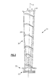
Figure 2 is a general sectional view of a gas turbine engine LPT blade; -
Figure 3 is a perspective view of the LPT blade ofFigure 2 ; -
Figure 4 is a perspective view of the LPT blade with a negative taper ratio; -
Figure 5 is an exploded view of a LPT blade; and -
Figure 6 is an exploded view of another embodiment of the LPT blade; -
Figure 1 schematically illustrates agas turbine engine 20 which generally includes a fan section F, a compressor section C, a combustor section G, a turbine section T, an augmentor section A, and an exhaust duct assembly E. The compressor section C, combustor section G, and turbine section T are generally referred to as the core engine. An engine longitudinal axis X is centrally disposed and extends longitudinally through these sections. While a particular gas turbine engine is schematically illustrated in the disclosed non-limiting embodiment, it should be understood that the disclosure is applicable to other gas turbine engine configurations, including, for example, gas turbines for power generation, turbojet engines, high bypass turbofan engines, low bypass turbofan engines, turboshaft engines, etc. - Within and aft of the combustor section G, engine components may be internally cooled or uncooled dependant on the temperatures of the hot combustion core gases. For example, a High Pressure Turbine (HPT) of the turbine section T may be cooled, while a Low Pressure Turbine (LPT) may be uncooled. It should be understood that various cooling paths and flows may alternatively or additionally be provided.
- The uncooled Low Pressure Turbine (LPT) section of the
gas turbine engine 20 includes arotor assembly 22 along the engine longitudinal axis X. Therotor assembly 22 includes a plurality ofblades 24 circumferentially disposed around arespective rotor disk 26. It should be understood that a multiple of discs may be contained within each engine section and that although the LPT section is illustrated and described in the disclosed embodiment, other sections will also benefit herefrom. - With reference to
Figure 2 , eachblade 24 generally includes aroot section 30, aplatform section 32, and an airfoil section 34 along a longitudinal axis B. The outer edge of each airfoil section 34 is anairfoil tip section 34T which is adjacent the blade outer air seal assembly (not shown). The airfoil section 34 defines asuction side 34S and apressure side 34P (Figure 3 ). - The
blade 24 is hollowed to define acavity 34C, by casting or other conventional process, from theairfoil tip section 34T toward theroot section 30. Thecavity 34C extends towards theroot section 30 from theairfoil tip section 34T but not through theroot section 30. Thecavity 34C may be filled with various honeycomb, rib or fin structure. Alternatively, or in addition, thecavity 34C may filled with a gas or contain a vacuum. - Wall thickness at each section (illustrated in phantom) may be determined, for example, by minimum material manufacturing limits or maximum stress allowable limits, generally whichever is less. This maintains a high stiffness to weight ratio of the airfoil for better vibration response while maintaining a nearly constant mean stress along the span.
- The
blade 24 may have a zero, positive (Figure 3 ) or negative (Figure 4 ) taper ratio such that the taper can be optimized for maximum efficiency. It should be understood that a positive taper ratio defines a longer chord at theairfoil tip section 34T that at theroot section 30. A longer chord at theairfoil tip section 34T reduces loading with a reduced airfoil thickness at theroot section 30 to minimize blockage for an overall efficiency gain. - With reference to
Figure 5 , theairfoil tip section 34T receives atip shroud 40 to close thecavity 34C. Thetip shroud 40 may be attached in various manners through welding, brazing, bonding or other such permanent attachment. Thetip shroud 40 includesrails 42 which define knife edge seals with stationary engine structure (not shown). Therails 42 define full annular knife seals when assembled to therotor disk 22. That is, therails 42 on oneblade 24 interface with therails 42 on anadjacent blade 24 to form a full turbine ring tip shroud. - With reference to
Figure 6 , theairfoil tip section 34T may alternatively be formed with anintegral tip shroud 44 with rails which receives aseparate cover plate 50 to close thecavity 34C. That is, thecover plate 50 is sized to plug thecavity 34C and may be generally airfoil shaped. Thecover plate 50 may be attached in various manners through welding, brazing, bonding or other such permanent attachment. - In addition to the performance benefits, airfoils that are hollowed from the
airfoil tip section 34T toward theroot section 30 facilitate a solid attachment to therotor disk 22. Asolid root section 30 provides for reduced circumferential thickness requirements and reduced potential of pitch limitations on the number of airfoils that will fit around the circumference of therotor disk 22. - It should be understood that although a particular component arrangement is disclosed in the illustrated embodiment, other arrangement will benefit from the instant disclosure.
- Although particular step sequences are shown, described, and claimed, it should be understood that steps may be performed in any order, separated or combined unless otherwise indicated and will still benefit from the present disclosure.
- The foregoing description is exemplary rather than defined by the limitations within. Many modifications and variations are possible in light of the above teachings. Non-limiting embodiments are disclosed herein, however, one of ordinary skill in the art would recognize that certain modifications would come within the scope of this disclosure. It is, therefore, to be understood that within the scope of the appended claims, the disclosure may be practiced otherwise than as specifically described. For that reason the following claims should be studied to determine the true scope and content of this disclosure.
Claims (12)
- A rotor blade (24) for a turbine engine (20) comprising:a platform section (32);a root section (30) which extends from said platform section (32); andan airfoil section (34) which extends from said platform section (32) opposite said root section (30), said airfoil section (34) defines a cavity (34C) which extends from an airfoil tip section (34T) toward said root section (30).
- The rotor blade as recited in claim 1, wherein said root section (30) is solid.
- The rotor blade as recited in claim 1 or 2, wherein said cavity (34C) decreases toward said root section (30).
- The rotor blade as recited in any preceding claim, wherein said cavity (34C) extends from a leading edge to a trailing edge at said airfoil tip section (34T).
- The rotor blade as recited in any preceding claim, wherein said airfoil section (34) defines a positive taper ratio.
- The rotor blade as recited in any preceding claim, wherein said rotor blade (24) is a low pressure turbine blade.
- The rotor blade as recited in any preceding claim, wherein said airfoil tip section (34T) receives a cover plate (50) to close said cavity (34C).
- The rotor blade as recited in claim 7, further comprising a rail (42) which extends from said cover plate (50).
- A method of forming a rotor blade (24) comprising:defining a cavity (34C) which extends from an airfoil tip section (34T) toward a root section (30) of an airfoil section (34) of a turbine blade.
- The method as recited in claim 9, further comprising:defining a wall thickness about the cavity (34C) with respect to a minimum material manufacturing limit.
- The method as recited in claim 9, further comprising:defining a wall thickness about the cavity (34C) with respect to a maximum stress allowable limit.
- The method as recited in claim 9, further comprising:defining a wall thickness about the cavity (34C) with respect to a minimum material manufacturing limit or maximum stress allowable limit, whichever is less.
Applications Claiming Priority (1)
| Application Number | Priority Date | Filing Date | Title |
|---|---|---|---|
| US12/843,832 US8740567B2 (en) | 2010-07-26 | 2010-07-26 | Reverse cavity blade for a gas turbine engine |
Publications (3)
| Publication Number | Publication Date |
|---|---|
| EP2412926A2 true EP2412926A2 (en) | 2012-02-01 |
| EP2412926A3 EP2412926A3 (en) | 2013-07-31 |
| EP2412926B1 EP2412926B1 (en) | 2019-05-08 |
Family
ID=44509921
Family Applications (1)
| Application Number | Title | Priority Date | Filing Date |
|---|---|---|---|
| EP11173975.1A Not-in-force EP2412926B1 (en) | 2010-07-26 | 2011-07-14 | Hollow blade for a gas turbine |
Country Status (2)
| Country | Link |
|---|---|
| US (1) | US8740567B2 (en) |
| EP (1) | EP2412926B1 (en) |
Cited By (5)
| Publication number | Priority date | Publication date | Assignee | Title |
|---|---|---|---|---|
| WO2014100528A1 (en) * | 2012-12-21 | 2014-06-26 | General Electric Company | Turbine rotor blades having mid-span shrouds |
| WO2014137441A1 (en) * | 2012-12-21 | 2014-09-12 | General Electric Company | Rotor blade and corresponding manufacturing method |
| CN105697068A (en) * | 2016-04-19 | 2016-06-22 | 中国船舶重工集团公司第七�三研究所 | Reversing turbine double-channel one-belt one-movable-blade structure used for gas turbine |
| CN105736060A (en) * | 2016-04-22 | 2016-07-06 | 中国船舶重工集团公司第七�三研究所 | Backing turbine double-channel integral impeller |
| EP2921648B1 (en) | 2014-03-20 | 2018-12-26 | Ansaldo Energia Switzerland AG | Gas turbine blade comprising bended leading and trailing edges |
Families Citing this family (8)
| Publication number | Priority date | Publication date | Assignee | Title |
|---|---|---|---|---|
| EP3027853B1 (en) * | 2013-07-29 | 2021-05-19 | Raytheon Technologies Corporation | Gas turbine engine cmc airfoil assembly |
| US20150345310A1 (en) * | 2014-05-29 | 2015-12-03 | General Electric Company | Turbine bucket assembly and turbine system |
| US20160084103A1 (en) * | 2014-09-24 | 2016-03-24 | Honeywell International Inc. | Shrouded bonded turbine rotors and methods for manufacturing the same |
| WO2016108105A1 (en) * | 2014-12-29 | 2016-07-07 | Husqvarna Ab | User identification and customization for outdoor power machines |
| US10494932B2 (en) * | 2017-02-07 | 2019-12-03 | General Electric Company | Turbomachine rotor blade cooling passage |
| US11118462B2 (en) | 2019-01-24 | 2021-09-14 | Pratt & Whitney Canada Corp. | Blade tip pocket rib |
| US11371359B2 (en) | 2020-11-26 | 2022-06-28 | Pratt & Whitney Canada Corp. | Turbine blade for a gas turbine engine |
| CN118339363A (en) * | 2021-12-28 | 2024-07-12 | 三菱重工业株式会社 | Rotating blade and gas turbine equipped with the same |
Family Cites Families (36)
| Publication number | Priority date | Publication date | Assignee | Title |
|---|---|---|---|---|
| US1748364A (en) | 1928-10-09 | 1930-02-25 | Westinghouse Electric & Mfg Co | Method of making turbine blades |
| GB584580A (en) | 1943-12-28 | 1947-01-17 | Masch Fabrick Oerlikon | Improvements in or relating to turbine blades |
| GB602530A (en) | 1945-10-16 | 1948-05-28 | Bristol Aeroplane Co Ltd | Improvements in or relating to gas turbines |
| GB623041A (en) | 1946-08-31 | 1949-05-11 | Birmingham Small Arms Co Ltd | Improvements in or relating to the manufacture of metal articles |
| GB625693A (en) | 1946-10-25 | 1949-07-01 | Brush Electrical Eng | Improvements in and relating to turbine blades |
| GB619107A (en) | 1946-11-21 | 1949-03-03 | Brush Electrical Eng | Improvements in and relating to turbine blading |
| US2787441A (en) | 1952-03-05 | 1957-04-02 | Thompson Prod Inc | Hollow turbine bucket |
| NL104493C (en) | 1957-06-07 | |||
| US2966331A (en) | 1958-03-11 | 1960-12-27 | Orenda Engines Ltd | Hollow, air cooled turbine blades |
| US3066910A (en) | 1958-07-09 | 1962-12-04 | Thompson Ramo Wooldridge Inc | Cooled turbine blade |
| GB1400285A (en) | 1972-08-02 | 1975-07-16 | Rolls Royce | Hollow cooled vane or blade for a gas turbine engine |
| US3806276A (en) | 1972-08-30 | 1974-04-23 | Gen Motors Corp | Cooled turbine blade |
| US4214355A (en) * | 1977-12-21 | 1980-07-29 | General Electric Company | Method for repairing a turbomachinery blade tip |
| US4519745A (en) | 1980-09-19 | 1985-05-28 | Rockwell International Corporation | Rotor blade and stator vane using ceramic shell |
| GB2121483B (en) | 1982-06-08 | 1985-02-13 | Rolls Royce | Cooled turbine blade for a gas turbine engine |
| US4582467A (en) | 1983-12-22 | 1986-04-15 | United Technologies Corporation | Two stage rotor assembly with improved coolant flow |
| US4540339A (en) * | 1984-06-01 | 1985-09-10 | The United States Of America As Represented By The Secretary Of The Air Force | One-piece HPTR blade squealer tip |
| US5429877A (en) * | 1993-10-20 | 1995-07-04 | The United States Of America As Represented By The Secretary Of The Air Force | Internally reinforced hollow titanium alloy components |
| US5873699A (en) * | 1996-06-27 | 1999-02-23 | United Technologies Corporation | Discontinuously reinforced aluminum gas turbine guide vane |
| EP0894558A1 (en) * | 1997-07-29 | 1999-02-03 | Siemens Aktiengesellschaft | Turbine blade and method of fabrication of a turbine blade |
| EP1283325A1 (en) * | 2001-08-09 | 2003-02-12 | Siemens Aktiengesellschaft | Turbomachine blade and method for production of such a blade |
| US6869270B2 (en) | 2002-06-06 | 2005-03-22 | General Electric Company | Turbine blade cover cooling apparatus and method of fabrication |
| GB2394751A (en) | 2002-11-02 | 2004-05-05 | Rolls Royce Plc | Anti creep turbine blade with internal cavity |
| DE10301755A1 (en) | 2003-01-18 | 2004-07-29 | Rolls-Royce Deutschland Ltd & Co Kg | Fan blade for a gas turbine engine |
| FR2852999B1 (en) * | 2003-03-28 | 2007-03-23 | Snecma Moteurs | TURBOMACHINE RIDDLE AUBE AND METHOD OF MANUFACTURING THE SAME |
| GB2405186B (en) * | 2003-08-20 | 2005-10-26 | Rolls Royce Plc | A component with internal damping |
| US7001152B2 (en) * | 2003-10-09 | 2006-02-21 | Pratt & Wiley Canada Corp. | Shrouded turbine blades with locally increased contact faces |
| DE10349073A1 (en) | 2003-10-14 | 2005-05-19 | Rolls-Royce Deutschland Ltd & Co Kg | Hollow fan blade for aircraft engines and method for their production |
| US7104762B2 (en) * | 2004-01-06 | 2006-09-12 | General Electric Company | Reduced weight control stage for a high temperature steam turbine |
| US7029235B2 (en) | 2004-04-30 | 2006-04-18 | Siemens Westinghouse Power Corporation | Cooling system for a tip of a turbine blade |
| EP1591625A1 (en) * | 2004-04-30 | 2005-11-02 | ALSTOM Technology Ltd | Gas turbine blade shroud |
| US7189064B2 (en) * | 2004-05-14 | 2007-03-13 | General Electric Company | Friction stir welded hollow airfoils and method therefor |
| US7334997B2 (en) * | 2005-09-16 | 2008-02-26 | General Electric Company | Hybrid blisk |
| US7942639B2 (en) | 2006-03-31 | 2011-05-17 | General Electric Company | Hybrid bucket dovetail pocket design for mechanical retainment |
| US7600977B2 (en) * | 2006-05-08 | 2009-10-13 | General Electric Company | Turbine blade tip cap |
| US8322986B2 (en) | 2008-07-29 | 2012-12-04 | General Electric Company | Rotor blade and method of fabricating the same |
-
2010
- 2010-07-26 US US12/843,832 patent/US8740567B2/en not_active Expired - Fee Related
-
2011
- 2011-07-14 EP EP11173975.1A patent/EP2412926B1/en not_active Not-in-force
Non-Patent Citations (1)
| Title |
|---|
| None |
Cited By (5)
| Publication number | Priority date | Publication date | Assignee | Title |
|---|---|---|---|---|
| WO2014100528A1 (en) * | 2012-12-21 | 2014-06-26 | General Electric Company | Turbine rotor blades having mid-span shrouds |
| WO2014137441A1 (en) * | 2012-12-21 | 2014-09-12 | General Electric Company | Rotor blade and corresponding manufacturing method |
| EP2921648B1 (en) | 2014-03-20 | 2018-12-26 | Ansaldo Energia Switzerland AG | Gas turbine blade comprising bended leading and trailing edges |
| CN105697068A (en) * | 2016-04-19 | 2016-06-22 | 中国船舶重工集团公司第七�三研究所 | Reversing turbine double-channel one-belt one-movable-blade structure used for gas turbine |
| CN105736060A (en) * | 2016-04-22 | 2016-07-06 | 中国船舶重工集团公司第七�三研究所 | Backing turbine double-channel integral impeller |
Also Published As
| Publication number | Publication date |
|---|---|
| US20120020805A1 (en) | 2012-01-26 |
| EP2412926A3 (en) | 2013-07-31 |
| US8740567B2 (en) | 2014-06-03 |
| EP2412926B1 (en) | 2019-05-08 |
Similar Documents
| Publication | Publication Date | Title |
|---|---|---|
| EP2412926B1 (en) | Hollow blade for a gas turbine | |
| EP2995777B1 (en) | Vane ring for a gas turbine engine | |
| EP2937515B1 (en) | Gas turbine engine with non-axisymmetric surface contoured vane platform | |
| EP2570607B1 (en) | Gas turbine engine with ceramic matrix composite static structure and rotor module, and corresponding method of tip clearance control | |
| CA2870740C (en) | Turbine airfoil with local wall thickness control | |
| US8360716B2 (en) | Nozzle segment with reduced weight flange | |
| US8562286B2 (en) | Dead ended bulbed rib geometry for a gas turbine engine | |
| US20140348664A1 (en) | Impingement-cooled turbine rotor | |
| JP2012026448A (en) | Components with bonded edges | |
| WO2010051110A9 (en) | Turbine nozzle with crenelated outer shroud flange | |
| US20250146418A1 (en) | Turbine incorporating splitters | |
| US8235652B2 (en) | Turbine nozzle segment | |
| US20120195742A1 (en) | Turbine bucket for use in gas turbine engines and methods for fabricating the same | |
| US11454118B2 (en) | Gas turbine engine rotor blade having a root section with composite and metallic portions | |
| US20180274381A1 (en) | Gas turbine engine component incorporating a seal slot | |
| EP3023594A1 (en) | Stator assembly with pad interface for a gas turbine engine | |
| EP2551468A1 (en) | Blade outer air seal assembly with passage joined cavities and corresponding operating method | |
| CN107091122B (en) | Turbine engine airfoil with cooling | |
| EP3578759A1 (en) | Airfoil and corresponding method of directing a cooling flow | |
| US10371162B2 (en) | Integrally bladed fan rotor | |
| US20220090504A1 (en) | Rotor blade for a gas turbine engine having a metallic structural member and a composite fairing | |
| US20210372285A1 (en) | Segment for a turbine rotor stage |
Legal Events
| Date | Code | Title | Description |
|---|---|---|---|
| AK | Designated contracting states |
Kind code of ref document: A2 Designated state(s): AL AT BE BG CH CY CZ DE DK EE ES FI FR GB GR HR HU IE IS IT LI LT LU LV MC MK MT NL NO PL PT RO RS SE SI SK SM TR |
|
| AX | Request for extension of the european patent |
Extension state: BA ME |
|
| PUAI | Public reference made under article 153(3) epc to a published international application that has entered the european phase |
Free format text: ORIGINAL CODE: 0009012 |
|
| PUAL | Search report despatched |
Free format text: ORIGINAL CODE: 0009013 |
|
| AK | Designated contracting states |
Kind code of ref document: A3 Designated state(s): AL AT BE BG CH CY CZ DE DK EE ES FI FR GB GR HR HU IE IS IT LI LT LU LV MC MK MT NL NO PL PT RO RS SE SI SK SM TR |
|
| AX | Request for extension of the european patent |
Extension state: BA ME |
|
| RIC1 | Information provided on ipc code assigned before grant |
Ipc: F01D 5/18 20060101AFI20130627BHEP |
|
| 17P | Request for examination filed |
Effective date: 20140131 |
|
| RBV | Designated contracting states (corrected) |
Designated state(s): AL AT BE BG CH CY CZ DE DK EE ES FI FR GB GR HR HU IE IS IT LI LT LU LV MC MK MT NL NO PL PT RO RS SE SI SK SM TR |
|
| RAP1 | Party data changed (applicant data changed or rights of an application transferred) |
Owner name: UNITED TECHNOLOGIES CORPORATION |
|
| STAA | Information on the status of an ep patent application or granted ep patent |
Free format text: STATUS: EXAMINATION IS IN PROGRESS |
|
| 17Q | First examination report despatched |
Effective date: 20170111 |
|
| GRAP | Despatch of communication of intention to grant a patent |
Free format text: ORIGINAL CODE: EPIDOSNIGR1 |
|
| STAA | Information on the status of an ep patent application or granted ep patent |
Free format text: STATUS: GRANT OF PATENT IS INTENDED |
|
| INTG | Intention to grant announced |
Effective date: 20181115 |
|
| GRAS | Grant fee paid |
Free format text: ORIGINAL CODE: EPIDOSNIGR3 |
|
| GRAA | (expected) grant |
Free format text: ORIGINAL CODE: 0009210 |
|
| STAA | Information on the status of an ep patent application or granted ep patent |
Free format text: STATUS: THE PATENT HAS BEEN GRANTED |
|
| AK | Designated contracting states |
Kind code of ref document: B1 Designated state(s): AL AT BE BG CH CY CZ DE DK EE ES FI FR GB GR HR HU IE IS IT LI LT LU LV MC MK MT NL NO PL PT RO RS SE SI SK SM TR |
|
| REG | Reference to a national code |
Ref country code: GB Ref legal event code: FG4D |
|
| REG | Reference to a national code |
Ref country code: CH Ref legal event code: EP Ref country code: AT Ref legal event code: REF Ref document number: 1130409 Country of ref document: AT Kind code of ref document: T Effective date: 20190515 |
|
| REG | Reference to a national code |
Ref country code: DE Ref legal event code: R096 Ref document number: 602011058687 Country of ref document: DE Ref country code: IE Ref legal event code: FG4D |
|
| REG | Reference to a national code |
Ref country code: NL Ref legal event code: MP Effective date: 20190508 |
|
| REG | Reference to a national code |
Ref country code: LT Ref legal event code: MG4D |
|
| PG25 | Lapsed in a contracting state [announced via postgrant information from national office to epo] |
Ref country code: FI Free format text: LAPSE BECAUSE OF FAILURE TO SUBMIT A TRANSLATION OF THE DESCRIPTION OR TO PAY THE FEE WITHIN THE PRESCRIBED TIME-LIMIT Effective date: 20190508 Ref country code: LT Free format text: LAPSE BECAUSE OF FAILURE TO SUBMIT A TRANSLATION OF THE DESCRIPTION OR TO PAY THE FEE WITHIN THE PRESCRIBED TIME-LIMIT Effective date: 20190508 Ref country code: HR Free format text: LAPSE BECAUSE OF FAILURE TO SUBMIT A TRANSLATION OF THE DESCRIPTION OR TO PAY THE FEE WITHIN THE PRESCRIBED TIME-LIMIT Effective date: 20190508 Ref country code: PT Free format text: LAPSE BECAUSE OF FAILURE TO SUBMIT A TRANSLATION OF THE DESCRIPTION OR TO PAY THE FEE WITHIN THE PRESCRIBED TIME-LIMIT Effective date: 20190908 Ref country code: SE Free format text: LAPSE BECAUSE OF FAILURE TO SUBMIT A TRANSLATION OF THE DESCRIPTION OR TO PAY THE FEE WITHIN THE PRESCRIBED TIME-LIMIT Effective date: 20190508 Ref country code: NO Free format text: LAPSE BECAUSE OF FAILURE TO SUBMIT A TRANSLATION OF THE DESCRIPTION OR TO PAY THE FEE WITHIN THE PRESCRIBED TIME-LIMIT Effective date: 20190808 Ref country code: AL Free format text: LAPSE BECAUSE OF FAILURE TO SUBMIT A TRANSLATION OF THE DESCRIPTION OR TO PAY THE FEE WITHIN THE PRESCRIBED TIME-LIMIT Effective date: 20190508 Ref country code: ES Free format text: LAPSE BECAUSE OF FAILURE TO SUBMIT A TRANSLATION OF THE DESCRIPTION OR TO PAY THE FEE WITHIN THE PRESCRIBED TIME-LIMIT Effective date: 20190508 Ref country code: NL Free format text: LAPSE BECAUSE OF FAILURE TO SUBMIT A TRANSLATION OF THE DESCRIPTION OR TO PAY THE FEE WITHIN THE PRESCRIBED TIME-LIMIT Effective date: 20190508 |
|
| PG25 | Lapsed in a contracting state [announced via postgrant information from national office to epo] |
Ref country code: BG Free format text: LAPSE BECAUSE OF FAILURE TO SUBMIT A TRANSLATION OF THE DESCRIPTION OR TO PAY THE FEE WITHIN THE PRESCRIBED TIME-LIMIT Effective date: 20190808 Ref country code: RS Free format text: LAPSE BECAUSE OF FAILURE TO SUBMIT A TRANSLATION OF THE DESCRIPTION OR TO PAY THE FEE WITHIN THE PRESCRIBED TIME-LIMIT Effective date: 20190508 Ref country code: LV Free format text: LAPSE BECAUSE OF FAILURE TO SUBMIT A TRANSLATION OF THE DESCRIPTION OR TO PAY THE FEE WITHIN THE PRESCRIBED TIME-LIMIT Effective date: 20190508 Ref country code: GR Free format text: LAPSE BECAUSE OF FAILURE TO SUBMIT A TRANSLATION OF THE DESCRIPTION OR TO PAY THE FEE WITHIN THE PRESCRIBED TIME-LIMIT Effective date: 20190809 |
|
| REG | Reference to a national code |
Ref country code: AT Ref legal event code: MK05 Ref document number: 1130409 Country of ref document: AT Kind code of ref document: T Effective date: 20190508 |
|
| PG25 | Lapsed in a contracting state [announced via postgrant information from national office to epo] |
Ref country code: SK Free format text: LAPSE BECAUSE OF FAILURE TO SUBMIT A TRANSLATION OF THE DESCRIPTION OR TO PAY THE FEE WITHIN THE PRESCRIBED TIME-LIMIT Effective date: 20190508 Ref country code: RO Free format text: LAPSE BECAUSE OF FAILURE TO SUBMIT A TRANSLATION OF THE DESCRIPTION OR TO PAY THE FEE WITHIN THE PRESCRIBED TIME-LIMIT Effective date: 20190508 Ref country code: EE Free format text: LAPSE BECAUSE OF FAILURE TO SUBMIT A TRANSLATION OF THE DESCRIPTION OR TO PAY THE FEE WITHIN THE PRESCRIBED TIME-LIMIT Effective date: 20190508 Ref country code: DK Free format text: LAPSE BECAUSE OF FAILURE TO SUBMIT A TRANSLATION OF THE DESCRIPTION OR TO PAY THE FEE WITHIN THE PRESCRIBED TIME-LIMIT Effective date: 20190508 Ref country code: AT Free format text: LAPSE BECAUSE OF FAILURE TO SUBMIT A TRANSLATION OF THE DESCRIPTION OR TO PAY THE FEE WITHIN THE PRESCRIBED TIME-LIMIT Effective date: 20190508 Ref country code: CZ Free format text: LAPSE BECAUSE OF FAILURE TO SUBMIT A TRANSLATION OF THE DESCRIPTION OR TO PAY THE FEE WITHIN THE PRESCRIBED TIME-LIMIT Effective date: 20190508 |
|
| REG | Reference to a national code |
Ref country code: DE Ref legal event code: R097 Ref document number: 602011058687 Country of ref document: DE |
|
| PG25 | Lapsed in a contracting state [announced via postgrant information from national office to epo] |
Ref country code: SM Free format text: LAPSE BECAUSE OF FAILURE TO SUBMIT A TRANSLATION OF THE DESCRIPTION OR TO PAY THE FEE WITHIN THE PRESCRIBED TIME-LIMIT Effective date: 20190508 Ref country code: IT Free format text: LAPSE BECAUSE OF FAILURE TO SUBMIT A TRANSLATION OF THE DESCRIPTION OR TO PAY THE FEE WITHIN THE PRESCRIBED TIME-LIMIT Effective date: 20190508 Ref country code: MC Free format text: LAPSE BECAUSE OF FAILURE TO SUBMIT A TRANSLATION OF THE DESCRIPTION OR TO PAY THE FEE WITHIN THE PRESCRIBED TIME-LIMIT Effective date: 20190508 |
|
| REG | Reference to a national code |
Ref country code: CH Ref legal event code: PL |
|
| PLBE | No opposition filed within time limit |
Free format text: ORIGINAL CODE: 0009261 |
|
| STAA | Information on the status of an ep patent application or granted ep patent |
Free format text: STATUS: NO OPPOSITION FILED WITHIN TIME LIMIT |
|
| PG25 | Lapsed in a contracting state [announced via postgrant information from national office to epo] |
Ref country code: TR Free format text: LAPSE BECAUSE OF FAILURE TO SUBMIT A TRANSLATION OF THE DESCRIPTION OR TO PAY THE FEE WITHIN THE PRESCRIBED TIME-LIMIT Effective date: 20190508 |
|
| 26N | No opposition filed |
Effective date: 20200211 |
|
| REG | Reference to a national code |
Ref country code: BE Ref legal event code: MM Effective date: 20190731 |
|
| PG25 | Lapsed in a contracting state [announced via postgrant information from national office to epo] |
Ref country code: PL Free format text: LAPSE BECAUSE OF FAILURE TO SUBMIT A TRANSLATION OF THE DESCRIPTION OR TO PAY THE FEE WITHIN THE PRESCRIBED TIME-LIMIT Effective date: 20190508 |
|
| PG25 | Lapsed in a contracting state [announced via postgrant information from national office to epo] |
Ref country code: CH Free format text: LAPSE BECAUSE OF NON-PAYMENT OF DUE FEES Effective date: 20190731 Ref country code: SI Free format text: LAPSE BECAUSE OF FAILURE TO SUBMIT A TRANSLATION OF THE DESCRIPTION OR TO PAY THE FEE WITHIN THE PRESCRIBED TIME-LIMIT Effective date: 20190508 Ref country code: LU Free format text: LAPSE BECAUSE OF NON-PAYMENT OF DUE FEES Effective date: 20190714 Ref country code: BE Free format text: LAPSE BECAUSE OF NON-PAYMENT OF DUE FEES Effective date: 20190731 Ref country code: LI Free format text: LAPSE BECAUSE OF NON-PAYMENT OF DUE FEES Effective date: 20190731 |
|
| PG25 | Lapsed in a contracting state [announced via postgrant information from national office to epo] |
Ref country code: IE Free format text: LAPSE BECAUSE OF NON-PAYMENT OF DUE FEES Effective date: 20190714 |
|
| PG25 | Lapsed in a contracting state [announced via postgrant information from national office to epo] |
Ref country code: CY Free format text: LAPSE BECAUSE OF FAILURE TO SUBMIT A TRANSLATION OF THE DESCRIPTION OR TO PAY THE FEE WITHIN THE PRESCRIBED TIME-LIMIT Effective date: 20190508 |
|
| PG25 | Lapsed in a contracting state [announced via postgrant information from national office to epo] |
Ref country code: IS Free format text: LAPSE BECAUSE OF FAILURE TO SUBMIT A TRANSLATION OF THE DESCRIPTION OR TO PAY THE FEE WITHIN THE PRESCRIBED TIME-LIMIT Effective date: 20190908 |
|
| PG25 | Lapsed in a contracting state [announced via postgrant information from national office to epo] |
Ref country code: MT Free format text: LAPSE BECAUSE OF FAILURE TO SUBMIT A TRANSLATION OF THE DESCRIPTION OR TO PAY THE FEE WITHIN THE PRESCRIBED TIME-LIMIT Effective date: 20190508 Ref country code: HU Free format text: LAPSE BECAUSE OF FAILURE TO SUBMIT A TRANSLATION OF THE DESCRIPTION OR TO PAY THE FEE WITHIN THE PRESCRIBED TIME-LIMIT; INVALID AB INITIO Effective date: 20110714 |
|
| PG25 | Lapsed in a contracting state [announced via postgrant information from national office to epo] |
Ref country code: MK Free format text: LAPSE BECAUSE OF FAILURE TO SUBMIT A TRANSLATION OF THE DESCRIPTION OR TO PAY THE FEE WITHIN THE PRESCRIBED TIME-LIMIT Effective date: 20190508 |
|
| REG | Reference to a national code |
Ref country code: DE Ref legal event code: R081 Ref document number: 602011058687 Country of ref document: DE Owner name: RAYTHEON TECHNOLOGIES CORPORATION (N.D.GES.D.S, US Free format text: FORMER OWNER: UNITED TECHNOLOGIES CORPORATION, FARMINGTON, CONN., US |
|
| P01 | Opt-out of the competence of the unified patent court (upc) registered |
Effective date: 20230519 |
|
| PGFP | Annual fee paid to national office [announced via postgrant information from national office to epo] |
Ref country code: GB Payment date: 20230620 Year of fee payment: 13 |
|
| PGFP | Annual fee paid to national office [announced via postgrant information from national office to epo] |
Ref country code: FR Payment date: 20230724 Year of fee payment: 13 Ref country code: DE Payment date: 20230620 Year of fee payment: 13 |
|
| REG | Reference to a national code |
Ref country code: DE Ref legal event code: R119 Ref document number: 602011058687 Country of ref document: DE |
|
| GBPC | Gb: european patent ceased through non-payment of renewal fee |
Effective date: 20240714 |
|
| PG25 | Lapsed in a contracting state [announced via postgrant information from national office to epo] |
Ref country code: DE Free format text: LAPSE BECAUSE OF NON-PAYMENT OF DUE FEES Effective date: 20250201 |
|
| PG25 | Lapsed in a contracting state [announced via postgrant information from national office to epo] |
Ref country code: FR Free format text: LAPSE BECAUSE OF NON-PAYMENT OF DUE FEES Effective date: 20240731 |
|
| PG25 | Lapsed in a contracting state [announced via postgrant information from national office to epo] |
Ref country code: GB Free format text: LAPSE BECAUSE OF NON-PAYMENT OF DUE FEES Effective date: 20240714 |