EP2412907A2 - Interlocking mechanism - Google Patents
Interlocking mechanism Download PDFInfo
- Publication number
- EP2412907A2 EP2412907A2 EP20110175898 EP11175898A EP2412907A2 EP 2412907 A2 EP2412907 A2 EP 2412907A2 EP 20110175898 EP20110175898 EP 20110175898 EP 11175898 A EP11175898 A EP 11175898A EP 2412907 A2 EP2412907 A2 EP 2412907A2
- Authority
- EP
- European Patent Office
- Prior art keywords
- lever
- arm
- interlocking mechanism
- interlocking
- slide
- Prior art date
- Legal status (The legal status is an assumption and is not a legal conclusion. Google has not performed a legal analysis and makes no representation as to the accuracy of the status listed.)
- Withdrawn
Links
- 230000013011 mating Effects 0.000 claims description 7
- 230000000694 effects Effects 0.000 description 4
- 230000000903 blocking effect Effects 0.000 description 3
- 125000006850 spacer group Chemical group 0.000 description 3
- 238000009434 installation Methods 0.000 description 2
- 238000004519 manufacturing process Methods 0.000 description 2
- 238000000034 method Methods 0.000 description 2
- 238000007493 shaping process Methods 0.000 description 1
Images


Classifications
-
- E—FIXED CONSTRUCTIONS
- E05—LOCKS; KEYS; WINDOW OR DOOR FITTINGS; SAFES
- E05B—LOCKS; ACCESSORIES THEREFOR; HANDCUFFS
- E05B63/00—Locks or fastenings with special structural characteristics
- E05B63/18—Locks or fastenings with special structural characteristics with arrangements independent of the locking mechanism for retaining the bolt or latch in the retracted position
- E05B63/185—Preventing actuation of a bolt when the wing is open
-
- E—FIXED CONSTRUCTIONS
- E05—LOCKS; KEYS; WINDOW OR DOOR FITTINGS; SAFES
- E05C—BOLTS OR FASTENING DEVICES FOR WINGS, SPECIALLY FOR DOORS OR WINDOWS
- E05C9/00—Arrangements of simultaneously actuated bolts or other securing devices at well-separated positions on the same wing
- E05C9/06—Arrangements of simultaneously actuated bolts or other securing devices at well-separated positions on the same wing with three or more sliding bars
- E05C9/063—Arrangements of simultaneously actuated bolts or other securing devices at well-separated positions on the same wing with three or more sliding bars extending along three or more sides of the wing or frame
Definitions
- the invention concerns an interlocking mechanism located in a window sash, advantageously of a roof window, that enables longitudinal movement of an envelope ferrule or casement bolt sliding slat to be interlocked or unlocked.
- This mechanism is functionally connected to an envelope ferrule or a casement bolt, whose one part, secured to the window frame, is fixed, while the other one is a slidable member mechanically connected to a movable handle.
- casement bolt interlocking mechanism among others comprises a baseplate, a pivot lever with a sliding finger mounted on the baseplate in the plane perpendicular to the tilt plane of the window sash and the interlocking bolt mounted on the common axis with the pivot lever is known from EP 1 975 358 .
- a turn of the sliding finger causes a turn of the interlocking bolt, which may be in two positions - turning and non-turning, meaning respectively the interlocked and unlocked casement bolt.
- the finger head, as well as the sliding finger protrudes perpendicularly to the tilt plane in so that it mates the window frame while closing the sash.
- the closed sash keeps the mechanism in the turning position, in which the interlocking bolt position enables the movable part of the ferrule to be freely moved.
- the mechanism stays in the non-turning position.
- the interlock of travel of the movable part of the ferrule is based on the angular inserting of the bolt arms into sockets formed in the slidable part of the ferrule, which prevents their movement in both directions.
- casement bolt interlocking mechanism consists of among others a pivot lever installed pivotably on a baseplate in the plane perpendicular to the tilt plane of the window sash and the interlocking bolt mounted on the common axis with the pivot lever is known from the market.
- a turn of the pivot lever and thus the bolt, installed on the common axis is forced by contact with the window frame.
- the bolt turns by an angle not exceeding 30° from the non-interlocking position, parallel to the direction of travel of the movable part of the casement bolt into the interlocking position. This turn inserts the bolt arms into sockets formed in the slidable part of the ferrule, causing interlocking of possibility of its movement in both directions.
- the envelope ferrule interlocking mechanism comprises among others a baseplate, pivoting tilt mechanism and a latch interlocking the longitudinal movement of the slidable part of the ferrule.
- the interlocking latch is situated at the height of the pivoting handle.
- the lock operates on the principle that the interlocking latch protrudes from the window frame tilt plane and mates the movable part of the envelope ferrule while closing and opening the sash in the window frame.
- the interlocking latch is extended perpendicularly to the window frame tilt plane, and thus the pivoting movement of the handle, when the window frame is open or ajar, is prevented.
- the common feature of the mentioned solution is a pivoting interlocking member put in motion by the pressure of a lever placed on the side wall of the window sash on the window frame surface while closing the window.
- the lever members protruding beyond the window sash contour located in the area of the handle, make application of such a solution in the case of pivot or tilt-turn roof windows inconvenient.
- a characteristic feature of such windows is the proximity of internal window installations, e.g. linings, to the window path during closing. Therefore the risk of protruding members clashing with the window installation components increases.
- the objective of this solution is such a design of the mechanism interlocking the longitudinal movement of the sliding slat shifting the bolts of the envelope ferrule or casement bolt, that enables the position of the sliding slat to be easily changed by the turn of the handle in the closed position of the window sash and interlocks its extension in another position. It will protect the window frame structure from a damage by protruding bolts during closing of the sash window.
- the sliding slat is unlocked when the window sash is open, while changing its position from closed to open or tilted, and interlocked both in the open and the tilt position.
- this mechanism also efficiently prevents the possibility of handle turn and movement of the sliding slat when the window sash is ajar, protecting the window frame and other window components against a damage by protruding bolts during forced or accidental closing of the window sash.
- the essence of the invention is a mechanism using a slide shifted by a lever for interlocking the longitudinal movement of the sliding slat of the envelope ferrule or casement bolt, advantageously located in one on the window sash corners, which in the interlocked position completely prevents a shift of the sliding slat re-setting the bolts and consequently stops the possibility of a change of the position of handle or casement bolt holder while the window is open. While the window sash is closed the interlocking mechanism enables the sliding slat to shift freely and the bolts to be re-set into the position interlocking the window sash opening.
- the sliding slat has bearing surfaces for interlocking its movement, mating the slide.
- the sliding slat can have one bearing surface for interlocking movement only in one direction, or at least two bearing surfaces for interlocking movement in both directions. In the first case it is most often the end surface of the sliding slat. In the case of two bearing surfaces, they can be e.g. opposite walls of a rectangular or trapezoidal recess in the sliding slat.
- the slide positioned advantageously perpendicularly to the sliding slat may be advantageously L-shaped, where the shorter, interlocking arm contacts the bearing surface of the sliding slat, while the longer, guiding arm moves in the guide shaped in the guide bushing and is engaged to the lever.
- the guide bushing may be the only member with a hollowed guide with its shape matching the shape of the slide guiding arm, it can also be, for process reasons, a member with an open guide, covered e.g. with a spacer shielding the slide from the side profile structure and at the same time ensuring the possibility of only longitudinal guiding of the slide.
- the lever is shifted to the interlocking position of the mechanism with the spring tension force, which at the other end is restrained advantageously in the guide bushing body.
- a compressed spring is applicable.
- it should be a tension spring. Any springy component with a sufficient tension force and durability may also be used instead of a spring. It follows from the above that the interlocking position is a natural position of the mechanism and it may be changed to the unlocked position by applying an external exciting force.
- the slide is shifted to the unlocked position by a pressure of the lever onto the bumper installed on the side profile of the window frame structure while closing the window.
- a free movement of the envelope ferrule or casement bolt sliding slat is possible, and thus e.g. a turn of the handle.
- the interlocking slide arm in this position should be located on the opposite, relative to the lever position, side of the sliding slat.
- the spring is compressed - or stretched in the case of location on the opposite side of the lever holder. After insignificant opening of the window sash the pressure of the acting force arm on the bumper is released and the reverse movement of the slide to the interlocking position occurs, which is forced by the spring tension force.
- the slide makes an interlocking movement opposite to the direction of the window sash opened, thus the guiding arm of the slide is shorter, and the interlocking arm is on the same side of the sliding slat as the whole interlocking mechanism.
- the execution of the bearing surfaces in the sliding slat may be similar as in the case of the earlier described double-arm lever.
- the specificity of the solution of the mechanism with a single-arm lever requires a tension spring to be used, secured either to the guide bushing or directly to the window sash. The other end of the spring may be secured at any distance to the lever axis of rotation. It is restricted only by the required minimum tension force and design constraints.
- a design like this gives more freedom in shaping of the slide, which may have a similar L-shape, as in the previous case. It may also be a straight member or may have the shape resulting from other dependencies, in addition each of those solutions should contain a part guided in the guide and an interlocking part mating the bearing surfaces of the sliding slat.
- the design of the casement bolt and envelope ferrule interlocking mechanism is characterised by a relatively simple structure, low manufacturing cost and ease of assembly.
- a significant advantage of the proposed solution is the lack of uncovered and protruding beyond the window sash contour members of the interlocking mechanism, both in the unlocked and the interlocked position. It results from the location of the mechanism advantageously in the window sash corner, as well as from the fact that in the case of roof windows, the mechanism components are largely covered by the window sash sheeting. Therefore the risk of accidental damage of the structure or catching protruding members with a part of clothing is eliminated. Unquestionable advantages of such design are also aesthetic qualities and versatility of the solution, allowing the proposed solution to be applied in most of existing solutions of envelope ferrules and casement bolts.
- Fig. 1 in the form of an assembly drawing with exploded view
- Fig. 2 presents an isometric view of this mechanism in the unlocked position
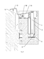
- Fig.3 which is a cross-section
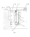
- Fig. 4 presents the interlocking mechanism with a double-arm lever in the interlocking position, installed in the window sash and mating the window frame
- Fig. 4 in the same arrangement shows the interlocking mechanism in the unlocked position
- Fig.5 shows the full cross-section of the mechanism with a single-arm lever in the unlocked position
- Fig. 6 in the same arrangement shows the interlocking mechanism in the locked position.
- the interlocking mechanism shown in connection with the window sash and components of the envelope ferrule on drawings Fig. 1 and Fig. 2 , located in one of the sash corners, consists of a slide 1 moving in the guide 2 formed in the guide bushing 3 and secured in a pivoting-sliding manner in the double-arm lever 4.
- the slide 1 is used for interlocking the longitudinal movement of the sliding slat 5 of the envelope ferrule or casement bolt.
- the slide as an interlocking member may be in two positions: the interlocking and the unlocked one.
- the sliding slat 5 has one bearing surface 6 advantageously being its end surface.
- the slide is advantageously L-shaped. Its interlocking arm 7 contacts the bearing surface 6 of the sliding slat 5.
- the slide is moved with the double-arm lever 4 through the guiding arm 8, sliding in the guide 2 with its shape matching the shape of this arm 8.
- the shape of the guide bushing 3 is determined, in its basic part, by a cylinder cut on its whole length with an advantageously flat surface parallel to the surface of the slide 1 sliding in the guides.
- the guide 2 is open on one side, which facilitates the slide 1 assembly.
- the guide 2 is covered with a spacer 9 causing the full interlocking of the unfavourable traversing of the slide.
- the spacer is used for angular restrain of the bushing after adjusting its position.
- the inconvenience caused by an unwanted possibility of the bushing turn in the round socket during operation may be eliminated by using different, not round shapes of the section of the bushing itself or the socket where the bushing is placed. However it is associated with a processing inconvenience of manufacturing such a socket.
- the slide 1 is shifted with the double-arm lever 4 supported pivotably on the lever holder 10.
- the useful force arm 11 of the double-arm lever 4 is connected to the slide 1 in a pivoting-sliding manner, and the acting force arm 12, while closing the window sash, mates the side profile of the window frame with a bumper 13 in the place of contact with the acting force arm 12.
- the direction of the exciting force effect is opposite to the direction of closing the window sash and perpendicular to its tilt plane.
- the slide 1 makes an unlocking movement in line with the direction of the window sash movement direction, as shown in Fig. 3 , assuming that the guide bushing 3 is installed perpendicularly to the tilt plane of the window sash.
- the double-arm lever 4 is held in the mechanism interlocking position, as in Fig. 3 with a spring 14 being compressed, secured to the useful force arm 11, which with its other end is restrained in the guide bushing 3 body.
- the spring 14 may be secured to the acting force arm 12 and in this case it should be a tension spring.
- the slide 1 is shifted, as shown in Fig. 4 , to the unlocked position by a pressure of the double-arm lever 12 on the bumper 13 installed on the side profile of the window frame while closing the window.
- the location of individual components of the mechanism in the unlocked position is shown in Fig. 4 , where arrows indicate the direction of the interlocking movement.
- a free movement of the envelope ferrule or casement bolt sliding slat 5 is possible, and thus e.g. a turn of the handle.
- the interlocking slide 1 arm 7 in this position is located on the opposite side of the sliding slat 5, relative to the position of other components of the interlocking mechanism.
- the spring 14 is compressed. After opening of the window sash the pressure of the acting force arm 12 on the bumper 13 is released and the return movement of the slide to the interlocking position occurs, which is forced by the spring 14 tension force.
- a single-arm lever 15 was used instead of the double-arm lever 4 from the first embodiment, which is shown in Fig. 5 .
- the lever design like this means the location of its point of support at one of its ends, opposite to the point of the force effect in the place of contact with the bumper 13.
- the slide 1 in this configuration may have the blocking part identical as in the first embodiment example in the form of a blocking arm 7, it may also have any other shape meeting the condition of engaging with the sliding slat 5 after re-setting the mechanism into the interlocking position.
- the slide 1 in the interlocking position makes an unlocking movement in the direction opposite to the direction of the window sash closing, and the interlocking arm 7 or another component of the slide 1 performing the interlocking function is on the same side of the sliding slat 5 as the whole interlocking mechanism.
- the mechanism in the unlocked position is shown in Fig. 5 .
- the slide may have the L-shape, or it may also be a straight member, in addition each of these solutions should contain a guiding arm 8 in the guide 2 and an interlocking part, mating the bearing surfaces of the sliding slat 5.
- the method of execution of the bearing surfaces in the sliding slat is similar as in the first embodiment example.
- the interlocking mechanism has the design and principle of operation essentially similar to the design described in the first example.
- the differentiating feature is the type of the spring used, which in this case is a torsion spring, advantageously wound up on a pin 18, connected with one end to the fixed lever holder 10, and with the other one to the double-arm lever 4.
Landscapes
- Engineering & Computer Science (AREA)
- Mechanical Engineering (AREA)
- Structural Engineering (AREA)
- Wing Frames And Configurations (AREA)
- Window Of Vehicle (AREA)
- Closing And Opening Devices For Wings, And Checks For Wings (AREA)
Applications Claiming Priority (1)
| Application Number | Priority Date | Filing Date | Title |
|---|---|---|---|
| PL392004A PL217844B1 (pl) | 2010-07-29 | 2010-07-29 | Mechanizm blokujący |
Publications (1)
| Publication Number | Publication Date |
|---|---|
| EP2412907A2 true EP2412907A2 (en) | 2012-02-01 |
Family
ID=44543070
Family Applications (1)
| Application Number | Title | Priority Date | Filing Date |
|---|---|---|---|
| EP20110175898 Withdrawn EP2412907A2 (en) | 2010-07-29 | 2011-07-29 | Interlocking mechanism |
Country Status (2)
| Country | Link |
|---|---|
| EP (1) | EP2412907A2 (pl) |
| PL (1) | PL217844B1 (pl) |
Citations (1)
| Publication number | Priority date | Publication date | Assignee | Title |
|---|---|---|---|---|
| EP1975358A2 (de) | 2007-03-27 | 2008-10-01 | Aug. Winkhaus GmbH & Co. KG | Schaltsperre |
-
2010
- 2010-07-29 PL PL392004A patent/PL217844B1/pl unknown
-
2011
- 2011-07-29 EP EP20110175898 patent/EP2412907A2/en not_active Withdrawn
Patent Citations (1)
| Publication number | Priority date | Publication date | Assignee | Title |
|---|---|---|---|---|
| EP1975358A2 (de) | 2007-03-27 | 2008-10-01 | Aug. Winkhaus GmbH & Co. KG | Schaltsperre |
Also Published As
| Publication number | Publication date |
|---|---|
| PL392004A1 (pl) | 2012-01-30 |
| PL217844B1 (pl) | 2014-08-29 |
Similar Documents
| Publication | Publication Date | Title |
|---|---|---|
| US5076015A (en) | Device for the sutter-like and tilt-down opening of a window or door-window | |
| US20140333074A1 (en) | Compression Latch | |
| US9140041B2 (en) | Compression latch | |
| EP1724424B1 (en) | Vehicle door lock | |
| US7338097B2 (en) | Latch assembly for a movable closure element | |
| US20030205903A1 (en) | Tilt latch mechanism for hung windows | |
| RU2007130447A (ru) | Вспомогательный охранный модуль для дверей, оснащенных открывающим устройством "анти-паника" | |
| US20040222643A1 (en) | Lock | |
| US7267377B2 (en) | Latch assembly for a movable closure element | |
| US7096538B2 (en) | Vehicle door hinge system | |
| CN108699873B (zh) | 用于连接可滑动且可翻转的扇的装配总成 | |
| US20060196236A1 (en) | Lock with pivoting release | |
| CA2276061A1 (en) | Actuating bar-type lock | |
| JP4669489B2 (ja) | スライドドア干渉防止構造 | |
| EP2412907A2 (en) | Interlocking mechanism | |
| US5020843A (en) | Crane hook latch with sliding lock bar | |
| NL2005577C2 (en) | Catch for a lock, assembly of a catch and lock and/or a closing element and a method for closing a closing element. | |
| EP1739256B1 (en) | Retractable strike for panic locks | |
| KR950010990B1 (ko) | 창 자물쇠 | |
| KR102714441B1 (ko) | 트렁크 개폐 조절 장치 | |
| EP2032786B1 (en) | Slip bolt, especially for rotating roof windows made of multi-chamber elements | |
| GB2340535A (en) | Locking mechanism | |
| CA1255465A (en) | Hinge | |
| GB2486473A (en) | Locking Mechanism | |
| KR20100011731A (ko) | 트렁크 리드의 토션바 토크 조절장치 |
Legal Events
| Date | Code | Title | Description |
|---|---|---|---|
| AK | Designated contracting states |
Kind code of ref document: A2 Designated state(s): AL AT BE BG CH CY CZ DE DK EE ES FI FR GB GR HR HU IE IS IT LI LT LU LV MC MK MT NL NO PL PT RO RS SE SI SK SM TR |
|
| AX | Request for extension of the european patent |
Extension state: BA ME |
|
| PUAI | Public reference made under article 153(3) epc to a published international application that has entered the european phase |
Free format text: ORIGINAL CODE: 0009012 |
|
| 17P | Request for examination filed |
Effective date: 20130205 |
|
| STAA | Information on the status of an ep patent application or granted ep patent |
Free format text: STATUS: THE APPLICATION HAS BEEN WITHDRAWN |
|
| 18W | Application withdrawn |
Effective date: 20130430 |