EP2412878A1 - A trap assembly and a lavatory comprising said trap assembly - Google Patents
A trap assembly and a lavatory comprising said trap assembly Download PDFInfo
- Publication number
- EP2412878A1 EP2412878A1 EP10190069A EP10190069A EP2412878A1 EP 2412878 A1 EP2412878 A1 EP 2412878A1 EP 10190069 A EP10190069 A EP 10190069A EP 10190069 A EP10190069 A EP 10190069A EP 2412878 A1 EP2412878 A1 EP 2412878A1
- Authority
- EP
- European Patent Office
- Prior art keywords
- filter
- trap assembly
- adapter
- lavatory
- cover
- Prior art date
- Legal status (The legal status is an assumption and is not a legal conclusion. Google has not performed a legal analysis and makes no representation as to the accuracy of the status listed.)
- Withdrawn
Links
- 239000002351 wastewater Substances 0.000 claims abstract description 15
- 238000007789 sealing Methods 0.000 claims abstract description 9
- 239000000919 ceramic Substances 0.000 claims description 3
- 238000000034 method Methods 0.000 claims description 2
- 230000000712 assembly Effects 0.000 description 2
- 238000000429 assembly Methods 0.000 description 2
- 238000007599 discharging Methods 0.000 description 1
- 239000007789 gas Substances 0.000 description 1
- 238000009434 installation Methods 0.000 description 1
Images

Classifications
-
- E—FIXED CONSTRUCTIONS
- E03—WATER SUPPLY; SEWERAGE
- E03C—DOMESTIC PLUMBING INSTALLATIONS FOR FRESH WATER OR WASTE WATER; SINKS
- E03C1/00—Domestic plumbing installations for fresh water or waste water; Sinks
- E03C1/12—Plumbing installations for waste water; Basins or fountains connected thereto; Sinks
- E03C1/26—Object-catching inserts or similar devices for waste pipes or outlets
-
- E—FIXED CONSTRUCTIONS
- E03—WATER SUPPLY; SEWERAGE
- E03C—DOMESTIC PLUMBING INSTALLATIONS FOR FRESH WATER OR WASTE WATER; SINKS
- E03C1/00—Domestic plumbing installations for fresh water or waste water; Sinks
- E03C1/12—Plumbing installations for waste water; Basins or fountains connected thereto; Sinks
- E03C1/22—Outlet devices mounted in basins, baths, or sinks
- E03C1/23—Outlet devices mounted in basins, baths, or sinks with mechanical closure mechanisms
-
- E—FIXED CONSTRUCTIONS
- E03—WATER SUPPLY; SEWERAGE
- E03C—DOMESTIC PLUMBING INSTALLATIONS FOR FRESH WATER OR WASTE WATER; SINKS
- E03C1/00—Domestic plumbing installations for fresh water or waste water; Sinks
- E03C1/12—Plumbing installations for waste water; Basins or fountains connected thereto; Sinks
- E03C1/26—Object-catching inserts or similar devices for waste pipes or outlets
- E03C1/262—Object-catching inserts or similar devices for waste pipes or outlets combined with outlet stoppers
Definitions
- the present invention relates to a trap assembly used in lavatories (sinks).
- Lavatory trap assemblies are used for discharging the waste water and isolating the installation gases from the environment. Trap assemblies start with a filter at the valve area and extend towards the inlet of the sanitary pipe line.
- a cover serving as a filter is disposed at the filter parts of the lavatories for preventing entrance of foreign matters into the sanitary pipe inlet and clogging of the trap assembly. While the said cover may be free on the filter, it may also be used together with the faucet.
- US6341391 discloses a hidden drain outlet structure for sinks.
- the said structure comprises a drain pipe, a drain head screwed to the drain pipe by a connection bolt and a filter attached to the drain head.
- the filter that is used prevents intrusion of pieces into the drain line.
- US2008282466 discloses a waste water pipe plug and a trap assembly for bathrooms and sinks.
- the trap assembly has a sealable structure, and it can be moved between the sealing position at which it is closed and the drainage position at which it is open.
- the objective of the present invention is to realize a trap assembly wherein a cover may be mounted on the filter.
- Another objective of the invention is to realize a trap assembly that is used together with a ceramic trap cover.
- the inventive trap assembly (1) essentially comprises
- the body (2) is fixed to the lavatory (L) by means of the connection member (6) which is passed through both the connection space (5) provided on the body (2) and the connection space (51) provided on the filter (4).
- a sealing member (3) between the body (2) and the lavatory (L) which prevents waste water from the lavatory (L) from going out of the body (2).
- a gasket is used as the sealing member (3).
- connection space (51) is located in the center of the filter (4), concentric with the connection space (5) provided on the body (2).
- the body (2) and the filter (4) are fixed on the lavatory (L) by means of the connection member (6) passed through the concentric connection spaces (5, 51).
- connection member (6) comprises
- connection member (6) When the connection member (6) is fixed to the body (2) via the filter (4), the body (2), the sealing member (3) and the filter (4) are fixed along the same axis.
- the adapter (9) comprises
- the plate (10) is preferably circular.
- the protrusion (11) is preferably located in the center of the surface of the plate (10) facing the filter (4).
- the protrusion (11) is fitted into the slot (7) to enable the adapter (9) to be fixed onto the filter (4).
- the protrusion (11) is tightened by the connection member (61) that is passed through the hole (8), and the cover (13) is prevented from accidentally coming off from the filter (4) due to coming off of the protrusion (11) from the slot (7).
- the channel (12), which is located on the surface of the plate (10) not facing the filter (4), is preferably circular. In the preferred embodiment of the invention, there are three channels (12) on the plate (10) whose diameters decrease towards the center of the plate (10). Connection of the cover (13) to the adapter (9) is strengthened by increasing the number of channels (12).
- the cover (13) is fixed to the adapter (9) by adhesion method.
- the cover (13) is ceramic.
- the body (2) is fastened to the lower part of the waste water drain hole (B) such that there will be the sealing member (3) between the body (2) and the lavatory (L), and after the filter (4) is arranged at the upper part of the same hole (B), the two parts (2, 4) are fixed by means of a connection member (6).
- the cover (13) is secured onto the adapter (9) and fitted into the slot (7) via the protrusion (11).
- a space is formed which will allow the waste water to pass through the filter (4) and into the sanitary pipe inlet.
Landscapes
- Engineering & Computer Science (AREA)
- Environmental & Geological Engineering (AREA)
- Health & Medical Sciences (AREA)
- Life Sciences & Earth Sciences (AREA)
- Hydrology & Water Resources (AREA)
- Public Health (AREA)
- Water Supply & Treatment (AREA)
- Mechanical Engineering (AREA)
- Sink And Installation For Waste Water (AREA)
Abstract
The inventive trap assembly (1) comprises at least one body (2), which is positioned below the lavatory (L) waste water drain hole (B), is connected to the sanitary pipe inlet, and has at least one connection space (5); at least one sealing member (3) which is placed between the body (2) and the lavatory (L); at least one filter (4), which is positioned above the lavatory (L) waste water drain hole (B), and has at least one connection space (51); at least one connection member (6) which enables connection of the filter (4) to the lavatory (L); at least one adapter (9) placed on the connection member (6); and at least one cover (13) which is fixed to the adapter (9) leaving an adequate space between itself and the filter (4) for the waste water to pass through.
Description
- The present invention relates to a trap assembly used in lavatories (sinks).
- Lavatory trap assemblies are used for discharging the waste water and isolating the installation gases from the environment. Trap assemblies start with a filter at the valve area and extend towards the inlet of the sanitary pipe line.
- A cover serving as a filter is disposed at the filter parts of the lavatories for preventing entrance of foreign matters into the sanitary pipe inlet and clogging of the trap assembly. While the said cover may be free on the filter, it may also be used together with the faucet.
- The United States patent document no.
US6341391 discloses a hidden drain outlet structure for sinks. The said structure comprises a drain pipe, a drain head screwed to the drain pipe by a connection bolt and a filter attached to the drain head. The filter that is used prevents intrusion of pieces into the drain line. - The United States patent document no.
US2008282466 discloses a waste water pipe plug and a trap assembly for bathrooms and sinks. In the said invention, the trap assembly has a sealable structure, and it can be moved between the sealing position at which it is closed and the drainage position at which it is open. - The objective of the present invention is to realize a trap assembly wherein a cover may be mounted on the filter.
- Another objective of the invention is to realize a trap assembly that is used together with a ceramic trap cover.
- A trap assembly realized to fulfill the objective of the present invention is illustrated in the accompanying figures wherein,
-
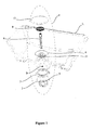
Figure 1 is the exploded perspective view of the inventive trap assembly on the lavatory. -
Figure 2 is the sectional view of the inventive trap assembly on the lavatory. -
Figure 3 is the sectional view of the connection member. -
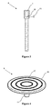
Figure 4 is the perspective view of the adapter. - The components in the figures are each given a reference numeral as follows:
- 1.
- Trap assembly
- 2.
- Body
- 3.
- Sealing member
- 4.
- Filter
- 5. ,51.
- Connection space
- 6. ,61.
- Connection member
- 7.
- Slot
- 8.
- Connection hole
- 9.
- Adapter
- 10.
- Plate
- 11.
- Protrusion
- 12.
- Channel
- 13.
- Cover
- 14.
- Space
- The inventive trap assembly (1) essentially comprises
- at least one body (2), which is positioned below the lavatory (L) waste water drain hole (B), is connected to the sanitary pipe inlet and has at least one connection space (5),
- at least one sealing member (3) which is placed between the body (2) and the lavatory (L),
- at least one filter (4), which is positioned above the lavatory (L) waste water drain hole (B), and has at least one connection space (51),
- at least one connection member (6) which enables connection of the filter (4) to the lavatory (L),
- at least one adapter (9) placed on the connection member (6) and
- at least one cover (13) which is fixed to the adapter (9) by leaving an adequate space between itself and the filter (4) for the waste water to pass through.
- The body (2) is fixed to the lavatory (L) by means of the connection member (6) which is passed through both the connection space (5) provided on the body (2) and the connection space (51) provided on the filter (4). There is provided a sealing member (3) between the body (2) and the lavatory (L) which prevents waste water from the lavatory (L) from going out of the body (2). Preferably a gasket is used as the sealing member (3).
- There are holes provided on the filter (4) which enable passage of the waste water to the body (2). The connection space (51) is located in the center of the filter (4), concentric with the connection space (5) provided on the body (2). The body (2) and the filter (4) are fixed on the lavatory (L) by means of the connection member (6) passed through the concentric connection spaces (5, 51).
- The connection member (6) comprises
- at least one slot (7) on which the adapter (9) is disposed,
- at least one connection hole (8) and
- at least one connection member (61) which fixes the adapter (9) on the filter (4) upon being passed through the hole (8).
- When the connection member (6) is fixed to the body (2) via the filter (4), the body (2), the sealing member (3) and the filter (4) are fixed along the same axis.
- The adapter (9) comprises
- at least one plate (10) which the cover (13) contacts,
- at least one protrusion (11), which is located on the surface of the plate (10) facing the filter (4) and is fitted into the slot (7), and
- at least one channel (12), which is located on the surface of the plate (10) not facing the filter (4), and which enables the cover (13) to be fastened to the adapter (9).
- In the preferred embodiment of the invention, the plate (10) is preferably circular. The protrusion (11) is preferably located in the center of the surface of the plate (10) facing the filter (4).
- The protrusion (11) is fitted into the slot (7) to enable the adapter (9) to be fixed onto the filter (4). Upon fitting the protrusion (11) into the slot (7), the protrusion (11) is tightened by the connection member (61) that is passed through the hole (8), and the cover (13) is prevented from accidentally coming off from the filter (4) due to coming off of the protrusion (11) from the slot (7).
- The channel (12), which is located on the surface of the plate (10) not facing the filter (4), is preferably circular. In the preferred embodiment of the invention, there are three channels (12) on the plate (10) whose diameters decrease towards the center of the plate (10).
Connection of the cover (13) to the adapter (9) is strengthened by increasing the number of channels (12). - On the surface of the cover (13) that is connected to the adapter (9), there is provided a space (14) which corresponds to the adapter (9) plate (10) and which is big enough for the plate (10) to fit therein.
- In the preferred embodiment of the invention, the cover (13) is fixed to the adapter (9) by adhesion method.
- In the preferred embodiment of the invention, the cover (13) is ceramic.
- In the inventive trap assembly (1), firstly the body (2) is fastened to the lower part of the waste water drain hole (B) such that there will be the sealing member (3) between the body (2) and the lavatory (L), and after the filter (4) is arranged at the upper part of the same hole (B), the two parts (2, 4) are fixed by means of a connection member (6). After the said fixing, the cover (13) is secured onto the adapter (9) and fitted into the slot (7) via the protrusion (11). By fitting the cover (13) on the filter (4), a space is formed which will allow the waste water to pass through the filter (4) and into the sanitary pipe inlet.
- Within the framework of this basic concept, it is possible to develop various embodiments of the inventive trap assembly (1). The invention can not be limited to the examples described herein and it is essentially according to the claims.
Claims (11)
- A trap assembly (1) comprising- at least one body (2), which is positioned below the lavatory (L) waste water drain hole (B), is connected to the sanitary pipe inlet, and has at least one connection space (5),- at least one sealing member (3) which is placed between the body (2) and the lavatory (L),- at least one filter (4), which is positioned above the lavatory (L) waste water drain hole (B), and has at least one connection space (51),- at least one connection member (6) which enables connection of the filter (4) to the lavatory (L),- at least one adapter (9) placed on the connection member (6) and- at least one cover (13) which is fixed to the adapter (9) by leaving an adequate space between itself and the filter (4) for the waste water to pass through,and characterized by at least one connection member (6) having- at least one slot (7) on which the adapter (9) is disposed,- at least one connection hole (8) and- at least one connection member (61) which fixes the adapter (9) on the filter (4) upon being passed through the hole (8).
- A trap assembly (1) according to Claim 1, characterized by an adapter (9) comprising- at least one plate (10) which the cover (13) contacts,- at least one protrusion (11), which is located on the surface of the plate (10) facing the filter (4) and is fitted into the slot (7), and- at least one channel (12), which is located on the surface of the plate (10) not facing the filter (4), and which enables the cover (13) to be fastened to the adapter (9).
- A trap assembly (1) according to Claim 2, characterized by a plate (10) which is circular.
- A trap assembly (1) according to any of Claims 2 to 3, characterized by the protrusion (11) which is located in the center of the surface of the plate (10) facing the filter (4).
- A trap assembly (1) according to any of Claims 2 to 4, characterized by the protrusion (11) which, upon being fitted into the slot (7), is tightened by the connection member (61) that is passed through the hole (8) and enables to prevent the cover (13) from accidentally coming off from the filter (4).
- A trap assembly (1) according to any of Claims 2 to 5, characterized by a channel (12) which is circular.
- A trap assembly (6) according to Claim 1, characterized by three channels (12) whose diameters decrease towards the center of the plate (10).
- A trap assembly (1) according to any of the preceding claims, characterized by a space (14) on the surface of the cover (13) that is connected to the adapter (9), which space (14) corresponds to the adapter (9) plate (10) and is big enough for the plate (10) to fit therein.
- A trap assembly (1) according to Claim 8, characterized by a cover (13) fixed to the adapter (9) by adhesion method.
- A trap assembly (1) according to Claim 9, characterized by a cover (13) which is ceramic.
- A lavatory (L) characterized by a trap assembly (1) according to any of the preceding claims.
Applications Claiming Priority (1)
| Application Number | Priority Date | Filing Date | Title |
|---|---|---|---|
| TR2010/06285A TR201006285A2 (en) | 2010-07-29 | 2010-07-29 | A siphon group and a sink where it is used. |
Publications (1)
| Publication Number | Publication Date |
|---|---|
| EP2412878A1 true EP2412878A1 (en) | 2012-02-01 |
Family
ID=44942002
Family Applications (1)
| Application Number | Title | Priority Date | Filing Date |
|---|---|---|---|
| EP10190069A Withdrawn EP2412878A1 (en) | 2010-07-29 | 2010-11-05 | A trap assembly and a lavatory comprising said trap assembly |
Country Status (2)
| Country | Link |
|---|---|
| EP (1) | EP2412878A1 (en) |
| TR (1) | TR201006285A2 (en) |
Cited By (1)
| Publication number | Priority date | Publication date | Assignee | Title |
|---|---|---|---|---|
| FR2990966A1 (en) * | 2012-05-22 | 2013-11-29 | Godart Distrib | Stopper for water evacuation opening in continuous outflow basin, has plug cover mounted at upper end of central rod, including upper face made of material matched with that of basin and surmounting opening of stopper |
Citations (7)
| Publication number | Priority date | Publication date | Assignee | Title |
|---|---|---|---|---|
| GB1072840A (en) * | 1966-05-27 | 1967-06-21 | Walther Loffler | Waste pipe assembly for containers for liquids |
| US4825477A (en) * | 1987-08-04 | 1989-05-02 | Aranda John P | Hair retriever tub drain device |
| US6108828A (en) * | 1998-08-15 | 2000-08-29 | Cheng; Jip | Drain cover assembly |
| US6341391B1 (en) | 2001-01-08 | 2002-01-29 | Tsan-Hsiung Cheng | Hidden drain outlet structure for sink |
| DE202004008540U1 (en) * | 2004-05-28 | 2004-09-23 | Engel, Robert G. | Drain plug with strainer for sink and the like. |
| US7032254B1 (en) * | 2005-04-22 | 2006-04-25 | Weilong Dong | Plug for sink drainage |
| US20080282466A1 (en) | 2007-05-17 | 2008-11-20 | Jacuzzi Uk Group Plc | Drain hole waste trap and plug assembly |
-
2010
- 2010-07-29 TR TR2010/06285A patent/TR201006285A2/en unknown
- 2010-11-05 EP EP10190069A patent/EP2412878A1/en not_active Withdrawn
Patent Citations (7)
| Publication number | Priority date | Publication date | Assignee | Title |
|---|---|---|---|---|
| GB1072840A (en) * | 1966-05-27 | 1967-06-21 | Walther Loffler | Waste pipe assembly for containers for liquids |
| US4825477A (en) * | 1987-08-04 | 1989-05-02 | Aranda John P | Hair retriever tub drain device |
| US6108828A (en) * | 1998-08-15 | 2000-08-29 | Cheng; Jip | Drain cover assembly |
| US6341391B1 (en) | 2001-01-08 | 2002-01-29 | Tsan-Hsiung Cheng | Hidden drain outlet structure for sink |
| DE202004008540U1 (en) * | 2004-05-28 | 2004-09-23 | Engel, Robert G. | Drain plug with strainer for sink and the like. |
| US7032254B1 (en) * | 2005-04-22 | 2006-04-25 | Weilong Dong | Plug for sink drainage |
| US20080282466A1 (en) | 2007-05-17 | 2008-11-20 | Jacuzzi Uk Group Plc | Drain hole waste trap and plug assembly |
Cited By (1)
| Publication number | Priority date | Publication date | Assignee | Title |
|---|---|---|---|---|
| FR2990966A1 (en) * | 2012-05-22 | 2013-11-29 | Godart Distrib | Stopper for water evacuation opening in continuous outflow basin, has plug cover mounted at upper end of central rod, including upper face made of material matched with that of basin and surmounting opening of stopper |
Also Published As
| Publication number | Publication date |
|---|---|
| TR201006285A2 (en) | 2012-02-21 |
Similar Documents
| Publication | Publication Date | Title |
|---|---|---|
| US10626586B2 (en) | Sink and drain for sink | |
| CA2831282C (en) | Sink and drain for sink | |
| US8782824B2 (en) | Tub drain and overflow assembly | |
| KR101555700B1 (en) | Toilet | |
| PL2009187T3 (en) | Sanitary facility with a floor drain and method for assembling such a sanitary facility | |
| WO2007086736A3 (en) | Drain assembly | |
| EP1928628B1 (en) | Fixture for disposing of bodily waste having an anti-overflow feature and a method for making the same | |
| EP3505693B1 (en) | A draining device for sanitary fittings such as sinks | |
| EP2300670B1 (en) | Improved waste trap | |
| EP2412878A1 (en) | A trap assembly and a lavatory comprising said trap assembly | |
| RU2628275C2 (en) | Flushing system for toilet bowl | |
| US6802424B2 (en) | Strainer in shower bath tap valve | |
| US9765505B2 (en) | Air-gap faucet | |
| CA2853122A1 (en) | Water drainage device | |
| EP1491694B1 (en) | Drain water sump | |
| EP1936046A2 (en) | Overflow apparatus for sanitary fixtures | |
| JP4184416B2 (en) | Drainage vent | |
| JP2007092296A (en) | Rain water spray prevention device in relay drain device | |
| EP1666676B1 (en) | Odour trap | |
| JP2004124569A (en) | Red water discharge valve | |
| JP5502962B2 (en) | More | |
| EP1428944B1 (en) | System for making outlet assemblies for wash basins and sanitary articles in general | |
| CA2978657C (en) | Removable trap for lavatory sinks | |
| IE20120105A1 (en) | Water treatment apparatus | |
| EP2420630B1 (en) | Improved Waste Trap |
Legal Events
| Date | Code | Title | Description |
|---|---|---|---|
| AK | Designated contracting states |
Kind code of ref document: A1 Designated state(s): AL AT BE BG CH CY CZ DE DK EE ES FI FR GB GR HR HU IE IS IT LI LT LU LV MC MK MT NL NO PL PT RO RS SE SI SK SM TR |
|
| AX | Request for extension of the european patent |
Extension state: BA ME |
|
| PUAI | Public reference made under article 153(3) epc to a published international application that has entered the european phase |
Free format text: ORIGINAL CODE: 0009012 |
|
| STAA | Information on the status of an ep patent application or granted ep patent |
Free format text: STATUS: THE APPLICATION IS DEEMED TO BE WITHDRAWN |
|
| 18D | Application deemed to be withdrawn |
Effective date: 20120802 |