EP2412877B1 - Foamed-water generating plug - Google Patents
Foamed-water generating plug Download PDFInfo
- Publication number
- EP2412877B1 EP2412877B1 EP09842291.8A EP09842291A EP2412877B1 EP 2412877 B1 EP2412877 B1 EP 2412877B1 EP 09842291 A EP09842291 A EP 09842291A EP 2412877 B1 EP2412877 B1 EP 2412877B1
- Authority
- EP
- European Patent Office
- Prior art keywords
- water flow
- water
- air
- accelerated
- jet
- Prior art date
- Legal status (The legal status is an assumption and is not a legal conclusion. Google has not performed a legal analysis and makes no representation as to the accuracy of the status listed.)
- Active
Links
- XLYOFNOQVPJJNP-UHFFFAOYSA-N water Substances O XLYOFNOQVPJJNP-UHFFFAOYSA-N 0.000 title claims description 531
- 239000006260 foam Substances 0.000 claims description 71
- 238000005276 aerator Methods 0.000 claims description 67
- 238000009423 ventilation Methods 0.000 claims description 39
- 230000007423 decrease Effects 0.000 claims description 13
- 230000012447 hatching Effects 0.000 description 12
- 230000003247 decreasing effect Effects 0.000 description 7
- 230000002093 peripheral effect Effects 0.000 description 7
- 238000009434 installation Methods 0.000 description 6
- 238000000034 method Methods 0.000 description 6
- 239000007787 solid Substances 0.000 description 5
- 238000005406 washing Methods 0.000 description 5
- 239000011521 glass Substances 0.000 description 3
- 238000013459 approach Methods 0.000 description 2
- 230000000694 effects Effects 0.000 description 2
- 238000012545 processing Methods 0.000 description 2
- 238000011160 research Methods 0.000 description 2
- 239000000356 contaminant Substances 0.000 description 1
- 230000002542 deteriorative effect Effects 0.000 description 1
- 238000007599 discharging Methods 0.000 description 1
- 238000002474 experimental method Methods 0.000 description 1
- 238000011010 flushing procedure Methods 0.000 description 1
- 239000007788 liquid Substances 0.000 description 1
- 239000002245 particle Substances 0.000 description 1
Images


Classifications
-
- E—FIXED CONSTRUCTIONS
- E03—WATER SUPPLY; SEWERAGE
- E03C—DOMESTIC PLUMBING INSTALLATIONS FOR FRESH WATER OR WASTE WATER; SINKS
- E03C1/00—Domestic plumbing installations for fresh water or waste water; Sinks
- E03C1/02—Plumbing installations for fresh water
- E03C1/08—Jet regulators or jet guides, e.g. anti-splash devices
- E03C1/084—Jet regulators with aerating means
-
- B—PERFORMING OPERATIONS; TRANSPORTING
- B01—PHYSICAL OR CHEMICAL PROCESSES OR APPARATUS IN GENERAL
- B01F—MIXING, e.g. DISSOLVING, EMULSIFYING OR DISPERSING
- B01F23/00—Mixing according to the phases to be mixed, e.g. dispersing or emulsifying
- B01F23/20—Mixing gases with liquids
-
- B—PERFORMING OPERATIONS; TRANSPORTING
- B05—SPRAYING OR ATOMISING IN GENERAL; APPLYING FLUENT MATERIALS TO SURFACES, IN GENERAL
- B05B—SPRAYING APPARATUS; ATOMISING APPARATUS; NOZZLES
- B05B7/00—Spraying apparatus for discharge of liquids or other fluent materials from two or more sources, e.g. of liquid and air, of powder and gas
- B05B7/02—Spray pistols; Apparatus for discharge
- B05B7/04—Spray pistols; Apparatus for discharge with arrangements for mixing liquids or other fluent materials before discharge
- B05B7/0416—Spray pistols; Apparatus for discharge with arrangements for mixing liquids or other fluent materials before discharge with arrangements for mixing one gas and one liquid
- B05B7/0425—Spray pistols; Apparatus for discharge with arrangements for mixing liquids or other fluent materials before discharge with arrangements for mixing one gas and one liquid without any source of compressed gas, e.g. the air being sucked by the pressurised liquid
-
- E—FIXED CONSTRUCTIONS
- E03—WATER SUPPLY; SEWERAGE
- E03C—DOMESTIC PLUMBING INSTALLATIONS FOR FRESH WATER OR WASTE WATER; SINKS
- E03C1/00—Domestic plumbing installations for fresh water or waste water; Sinks
- E03C1/02—Plumbing installations for fresh water
- E03C1/04—Water-basin installations specially adapted to wash-basins or baths
-
- Y—GENERAL TAGGING OF NEW TECHNOLOGICAL DEVELOPMENTS; GENERAL TAGGING OF CROSS-SECTIONAL TECHNOLOGIES SPANNING OVER SEVERAL SECTIONS OF THE IPC; TECHNICAL SUBJECTS COVERED BY FORMER USPC CROSS-REFERENCE ART COLLECTIONS [XRACs] AND DIGESTS
- Y02—TECHNOLOGIES OR APPLICATIONS FOR MITIGATION OR ADAPTATION AGAINST CLIMATE CHANGE
- Y02A—TECHNOLOGIES FOR ADAPTATION TO CLIMATE CHANGE
- Y02A20/00—Water conservation; Efficient water supply; Efficient water use
- Y02A20/40—Protecting water resources
- Y02A20/411—Water saving techniques at user level
Definitions
- This invention relates to a water saving aerator attached to water delivery devices such as a water tap (including a general water tap and a special purpose water tap for laboratory use) and a shower head for saving the amount of the water flow and aerating the water for generating bubble foam water.
- a water tap including a general water tap and a special purpose water tap for laboratory use
- a shower head for saving the amount of the water flow and aerating the water for generating bubble foam water.
- Bubble foam water is required in many water taps including ordinary homes and in commercial facilities.
- the impression form use of the bubble foam water in washing is quite gentle. Therefore the bubble foam water is preferably used in washing glasses and the dishes because there is no possibility to a crack or damage the surface of the glasses and the dishes.
- the bubble foam water has little rebounding even if it hits the surface of the glasses and the dishes in washing, so there is no fear of splashing water around the sink and deteriorating the environment. Therefore, the bubble foam water preferably is used in many water taps not only in ordinary homes but also in the station, in the public facilities, in the laboratory in the research institute, and so on.
- one of the methods for making the bubble foam water is attaching a water saving aerator to the water delivery devices such as a water tap.
- the water saving aerator in the prior art comprises air intake holes for in taking outer air to the water flow as a basic structure. The outer air is mixed with the water flow via the air intake holes. In addition, the opening of the water delivery devices is covered by the net for cutting the water flow into small pieces.
- the bubble foam water is generated by mixing the outer air via air intake hole and cutting the water flow by installing several nets to the opening of the water delivery devices for cutting the water flow into small pieces.
- Document DE1038531 discloses an aerator with a nozzle opening and a hollow cone surrounded by a cylinder
- document US5826799 relates to a sprinkling head structure in which a liquid quickly passes through a trumpet-shaped water discharging passage to suck air thereinto
- document US4322292 discloses an aerator capable of aerating at a low flow rate.
- the conventional water saving aerator described in the prior art has the following problem.
- the conventional water saving aerator can generate the bubble foam water including rough bubble, but it cannot generate the bubble foam water including a high quality fine bubble.
- the conventional water saving aerator supplies the outer air from the air intake holes located on the side wall to the water flow, so the outer air is mixed roughly in to the running water flow by being introduced from the side direction.
- the size of the involved bubble water is about several millimeters. After being introduced into water flow, the bubble is cut by a net or several nets into small pieces according to the water flow cutting. The bubble foam water is generated in this manner.
- the conventional water saving aerator described in the prior art generates the bubble foam water by mixing roughly the outer air into water flow only at the position where the outer air is supplied from the side direction.
- the hole of the net is about several millimeters as expected and cannot generate fine bubble smaller than the hole of the net.
- the first approach for generating the fine bubble foam in the conventional water saving aerator is based on increasing the contact area for outer air and water flow.
- the vertical length of the apparatus becomes too large as the bubble foam water saving aerator to be attached to the water tap.
- the second approach for generating the fine bubble foam in the conventional water saving aerator is based on decreasing the mesh size of the net.
- the smaller the mesh size of the net becomes the larger the resistance to the water flow becomes.
- the bubble mixed in the bubble foam water larger than the mesh size of the net in the upper stream is difficult to pass through the mesh of the net. If the mesh size of the net reaches the sub-millimeter level, there is a risk that the bubble is blocked and remains inside of the water tap, and that the air intake via the air intake hole is obstructed. In addition, if the mesh size of the net reaches the sub-millimeter level, there is a risk that the suspended particle and contaminant remains and blocks the mesh of the net.
- a water saving aerator with the features of claim 1 is provided.
- the present inventor Masaaki TAKANO has studied and conducted the actual experiment repeatedly. He has confirmed that the air becomes fine bubble by being introduced and injected into the accelerated water flow jet at very high speed because the air jet is jetted accelerated by the air pressure generated by the accelerated water jet, and has confirmed that the high quality bubble foam water including fine bubble entirely can be generated.
- the quality of the bubble included in the bubble foam water flow can be adjusted by modifying the distance and skew between the accelerated water jet and the air intake hole installed in the side surface of the water flow cylinder. Because the air jet is jetted from the air intake hole at high speed, the velocity of the air jet jetted from the air intake hole can be adjusted by the air pressure decrease depending on the positional relationship between the accelerated water jet and the air intake hole, in addition, the velocity of the air jet jetted from the air intake hole can be adjusted by the air pressure decrease depending on the angle relationship between the skew of the accelerated water jet and the installation angle of the air intake hole to the water flow cylinder.
- the water saving aerator further comprises an accelerated water flow jet position adjusting mechanism for adjusting the distance between the air intake hole and the accelerated water flow jet jetted into the air cavity.
- the water saving aerator further comprises an accelerated water flow jet skew adjusting mechanism for adjusting the jet skew of the accelerated water flow jet jetted into the air cavity.
- the water saving aerator further comprises an air intake hole size adjusting mechanism for adjusting the width of the air intake hole and adjusting the velocity of the air flow jet jetted via the air intake hole, wherein the velocity of the air jetted into the accelerated water flow jet can be adjusted.
- the water saving aerator can adjust the skew of the ventilation pass to the side surface of the water flow cylinder.
- the skew of the air flow jet to the accelerated water flow jet can be adjusted to be larger than 0 degree and smaller than 90 degrees.
- the skew of the air flow jet to the accelerated water flow jet can be adjusted to be larger than 90 degree and smaller than 180 degrees.
- the water saving aerator further comprises a ventilation pass skew adjusting mechanism for adjusting the skew of the ventilation pass to the side surface of the water flow and the skew of the air flow jet to the accelerated water flow jet without fixing the skew of the ventilation pass to the side surface of the water flow.
- the water saving aerator further comprises a water flow cylinder width adjusting mechanism for adjusting the width of the water flow cylinder installed to the water flow forming portion.
- the adjustment can be done in the attached condition to the water tap; wherein the width of the accelerated water flow jet can be adjusted by operating the water flow cylinder width adjusting mechanism.
- the mixing status in the bubble foam water flow can be adjusted by adjusting the width of the accelerated water flow jet.
- the water saving aerator of the present invention utilizes the accelerated water flow jet.
- the number of the accelerated water flow jet may as one or more.
- the air can be injected from the air intake hole and the bubble foam water flow can be generated by decreasing the air pressure around the air intake hole.
- the air pressure can be adjusted by accelerating the water flow flowing in the water saving aerator by the accelerator.
- the air cavity can be supplied in the water flow cylinder by narrowing the width of the accelerated water flow jet smaller than that of the water flow cylinder.
- the accelerated water flow to be jet is jetted into the air cavity, and the air in the air cavity is introduced and be jetted with the accelerated water flow jet below at very high speed.
- the air pressure of the air cavity decreases, the air is jetted from the air intake hole and the bubble foam water flow is generated.
- the quality of the bubble included in the bubble foam water flow can be adjusted by adjusting the distance and skew between the accelerated water jet and the air intake hole installed in the side surface of the water flow cylinder.
- the velocity of the air jet jetted from the air intake hole can be adjusted by the positional relationship between the accelerated water jet and the air intake hole.
- the velocity of the air jet jetted from the air intake hole can be adjusted by the angle relationship between the skew of the accelerated water jet and the installation angle of the air intake hole to the water flow cylinder.
- a schematic view of the water saving aerator 100 is shown as an example of this embodiment 1.
- the water saving aerator 100 shown in Embodiment 1 can save water and generate the bubble foam water.
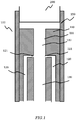
- Fig.1 is a schematic view of the water saving aerator 100 which does not form part of the present invention but represents background art that is useful for understanding the invention.
- the water saving aerator 100 is attached to the water delivery device 200 such as a water tap and generates the water flow as the bubble foam water flow.
- the water saving aerator 100 includes the water flow forming portion 110, the ventilation pass 120, the water flow cylinder 130 and the attachment 150.
- the water flow forming portion 110 is the portion for forming the water flow flowing in the water saving aerator 100.
- the water flow forming portion 110 includes the water flow accelerator 111 for accelerating the water flow.
- the structure for accelerating the water flow is not limited.
- the exemplary configuration of the water flow accelerator 111 shown in Fig.1 employs the structure for narrowing the width of the water flow at the accelerating position and the velocity of the water flow becomes large.
- the upper surface of the water flow accelerator 111 covers the opening of the water tap.
- the water flow accelerator 111 comprises a small through-hole in the center simply, and the center through-hole works as the water flow cylinder 130.
- the water flow accelerator 111 accepts the width A of the water flow from the attachment 150 and narrows the width B of the water flow for accelerating the water flow.
- the accelerated water flow is jetted in a pole shape.
- the accelerated water flow is not limited to the pole shape, and the accelerated water flow can be formed as various shape according to the shape of the water flow forming portion 110 and the water flow accelerator 111.
- the water saving effect can be obtained by employing the above-mentioned water flow accelerator 111.
- the water saving effect can be obtained by narrowing the width of the water flow with the water flow accelerator 111 to be smaller than that of the water flow cylinder 130.
- the attachment part 150 is a cylinder shape object attached to the water delivery devices 200 for connecting the water delivery devices 200 and the water flow forming portion 110.
- the attachment part 150 holds the water flow forming portion 110
- the internal diameter of the attachment part 150 is roughly the same as the outer diameter of the water delivery devices 200.
- the attachment part 150 is the device for attaching the water delivery devices 200.
- the attachment part 150 comprises screws for fastening to the water delivery devices 200.
- the screws in the attachment part 150 and the male screw installed around the water delivery devices 200 are screwed together, and the water saving aerator 100 is fastened to the water delivery devices 200 without leaking water.
- the opening of the water delivery devices 200 such as the water tap is standardized according to its use.
- the water taps used in the public facilities such as the laboratory and the research institute are standardized in the same shape and in the same size.
- the attachment part 150 comprises a cylinder 114 with a cone-shape and a flange 151 for supporting the edge of the water flow cylinder 130 below.
- the cone-shape cylinder 114 and the water flow cylinder 130 are suspended below the water delivery devices 200 via the flange 151 of the attachment 150.
- the ventilation pass 120 is the air pass that leads to the outer air.
- the air intake holes 121 are installed on the side surface of the water flow cylinder 130, and the outer air is supplied through the air intake holes 121 from the side surface of the water flow cylinder 130.
- the air intake holes 121 are installed on the side surface of the water flow cylinder 130 where velocity of the water flow becomes large due to the water flow accelerator 111.
- the air is supplied through the air intake holes 121 to the accelerated water flow jet jetted by the water flow accelerator 111, the air is introduced by the force given by the accelerated water flow jet, and the bubble foam water flow is generated.
- the air pressure around the air intake holes 121 decreases a lot because of the force given by the accelerated water flow jet to the lower stream, and the air is vacuumed and jetted via the air intake holes from the ventilation pass 120. The air is injected at the very fast speed to the accelerated water flow jet.
- Fig.2 is a schematic view showing that the bubble foam water flow is generated by flowing the water through the structure shown in Fig.1 .
- the water flow, the air flow and the bubble foam water flow to be generated are shown illustratively.
- the water flow from the upper stream turns into the bubble foam water flow at the position where the air intake holes 121 are installed because the air flow is jetted and injected into the water flow and the fine bubble are mixed.
- the air pressure around the air intake holes 121 decreases more and the velocity of the injected air flow jet becomes large. As a result, the amount of the bubbles injected to the water flow becomes large and the bubble size becomes finer.
- high quality bubble foam water flow can be obtained by injecting the air flow jet from the ventilation pass by decreasing the air pressure around the air intake holes by accelerating the water flow jet by the water flow accelerator as shown above.
- the water saving aerator employing the air cavity is shown as an example of this embodiment 2.
- the water saving aerator 100a includes the air cavity 131 in the water flow cylinder 130.
- the width of the accelerated water flow jet is narrowed to be smaller than that of the water flow cylinder 130.
- the air pressure around the air intake holes facing the air cavity 131 is decreased by jetting the accelerated water flow jet into the air cavity, and the air is vacuumed and jetted through the air intake holes 121 to generate the bubble foam water flow.
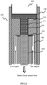
- Fig.3 is a schematic view of the water saving aerator 100a of the present invention in embodiment 2. The same as Fig.1 , all components are shown in cross-section for ease of understanding. Actually, the water saving aerator 100a is a solid of revolution shape.
- the water flow forming portion 110a is installed beneath the attachment part 150, and the accelerated water flow jet is jetted by the water flow accelerator 111a.
- the cone shape object 112 faces the inverted cone shape cylinder 113 in vertical direction. These are not contacted directly; these are facing with a certain gap 114.
- the gap 114 is formed between the outer surface of the cone shape object 112 and the internal surface of the inverted cone shape cylinder 113. This gap 114 is used as the water flow forming portion in the water saving aerator 100a.
- the cone shape object 112 and the ventilation pass 120 are shown above the inverted cone shape cylinder 113. However, the cone shape object 112 and the ventilation pass 120 are supported by the supporting object (not shown in Figure).
- the attachment part 150 is a cylinder shape object attached to the water delivery devices 200 for connecting the water delivery devices 200 and the water flow forming portion 110a.
- the attachment part 150 holds the water flow forming portion 110a.
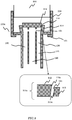
- Fig.4 is an exploded view showing the water flow forming portion 110a for ease of understanding.
- Fig.4 shows in a cross-sectional view. Most components are the solid of revolution shape, but the air intake holes 121 are not the solid of revolution shape. Pluralities of the air intake holes 121 are formed in the side surface of the water flow cylinder to the ventilation pass 120.
- the water flow accelerator 111a of the water flow forming portion 110a is formed by the combination of the outer surface of the cone shape object 112 and the internal surface of the inverted cone shape cylinder 113, and the gap 114 between these two objects works as the water flow of this water saving aerator 100a.
- Fig.4 (a) is a schematic view showing the cone shape object 112 and the ventilation pass 120.
- the ventilation pass 120 is a pipe shape pass.
- the air intake holes 121 are the holes on the side surface of the ventilation pass 120.
- Fig.4 (b) is a schematic view showing the inverted cone shape cylinder 113 and the water flow cylinder 130.
- the water flow cylinder 130 is a cylinder shape object.
- the water flow is accelerated when passing this gap 114 because the width of the gap 114 is smaller than that of the attachment part 150.
- the accelerated water flow jet formed by the water flow forming portion 110a is jetted as the cylindrical shape, in other words, a belt like round shape.
- the shape of the accelerated water flow jet is not limited to such a cylindrical shape, and the accelerated water flow can be formed as various shape according to the shape of the water flow forming portion 110a and the water flow accelerator 111a.
- a part of the space in the water flow cylinder 130 beneath the water flow accelerator 111a is used as the air cavity 131 always filled with air even if the water is running through the water saving aerator 100a.
- the width A of the water flow cylinder 130 beneath the water flow accelerator 111a is larger than the width B of the accelerated water flow jet, and the accelerated water flow jet can be jetted from the water flow accelerator 111a into the air contained in the air cavity 131 at high speed.
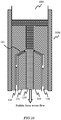
- Fig.5 is a schematic view showing the bubble foam water flow that is generated by flowing the water through the water saving aerator 100a of the present invention in embodiment 2.
- the water is accepted via the attachment 150 and led to the gap 114 of the water flow forming portion 110a, and the water flow is accelerated when passing the gap 114.
- the accelerated water flow is jetted into the air cavity 131 filled with the air.
- the width of the water flow cylinder 130 is larger than that of the accelerated water flow, so the air cavity can keep on containing the air.
- the accelerated water flow jet is jetted into the air cavity 131 filled with the air, and the accelerated water flow jet goes downstream, introducing the air in the air cavity. A part of the air in the air cavity 131 is flushed away, and the air pressure in the air cavity 131 is decreased.
- the air intake holes 121 are installed on the side surface of the air cavity 131, and the air pressure decrease occurs around the air intake holes 121, so the air pressure around the air intake holes 121 is decreased.
- the air intake holes 121 are connected to the outer air through the ventilation pass 120. The air is vacuumed from the outer air through the ventilation pass 120 into the air cavity at high speed.
- the velocity of the air flow jet depends on the diameter of the air intake holes 121, in this configuration, the velocity of the air flow jet jetted from the air intake holes 121 becomes large if the air is vacuumed into the air cavity at high speed. In this configuration, the accelerated water flow jet is jetted near the air intake holes 121, so the air flow jet is injected to the accelerated water flow jet.
- the air cavity 131 is filled with the air, and the accelerated water flow jet is jetted into the air contained in the air cavity.
- the air flow jet is jetted via the air intake holes 121 from the side direction, the air is injected into the accelerated water flow jet and bubbles are diffused entirely. As a result, the high quality bubble foam water flow is generated.
- the configuration shown above is the basic structure of the water saving aerator 100a employing the air cavity 131.
- the configuration including the accelerated water flow jet position adjusting mechanism is described. It is used for adjusting the distance between the accelerated water flow jet jetted into the air cavity 131 and the air intake holes 121.
- Fig.6 is a schematic view of the configuration including the accelerated water flow jet position adjusting mechanism.
- Fig.6 the water flow after turning into the bubble foam water flow is hatched with fine hatching finer than the hatching used for the water flow before turning into the bubble foam water flow.
- the accelerated water flow jet position adjusting mechanism is formed in the water flow forming portion 110a. It can adjust the position of the accelerated water flow jet to be formed by the water flow accelerator 111a, as a result, the distance between the accelerated water flow jet and the air intake holes 121 is adjusted.
- the method for adjusting the position of the accelerated water flow jet to be formed and adjusting the distance between the accelerated water flow jet and the air intake holes 121 is not limited, but in this configuration, the accelerated water flow jet position adjusting mechanism can adjust the position of the water flow forming portion 110a and the water flow accelerator 111a.
- the detailed structure of the accelerated water flow jet position adjusting mechanism is not shown, but it can move the object forming the gap 114 to the center position and to the peripheral position as shown by the arrows.
- the accelerated water flow jet position adjusting mechanism adjusts the position of the object forming the gap 114 from that shown in Fig.6 (a) to Fig.6 (b) , the position of the accelerated water flow jet is shifted in a center direction (near the air intake hole 121), and the distance between the accelerated water flow jet and the air intake hole 121 becomes smaller. If the accelerated water flow jet position adjusting mechanism adjusts the position of the object forming the gap 114 from that shown in Fig.6 (b) to Fig.6 (a) , the position of the accelerated water flow jet is shifted in a peripheral direction (far from the air intake hole 121), and the distance between the accelerated water flow jet and the air intake hole 121 becomes larger.
- the air contained in the air cavity 131 works as a resistance, so if the distance to the accelerated water flow jet becomes long, the velocity of the air flow jet decreases because of the resistance. Therefore, the velocity and the amount of the air flow jet in the air cavity can be controlled by adjusting the distance to the accelerated water flow jet.
- the amount of bubble can be controlled by adjusting the forming position of the accelerated water flow jet with the accelerated water flow jet position adjusting mechanism.
- the amount and the size of the bubbles mixed into the accelerated water flow jet depend on other conditions such as the amount of the water in the accelerated water flow jet, the velocity of the accelerated water flow jet, the width and the height of the air cavity 131 and the width of the air intake holes 121. Taking these conditions into account, the forming position of the accelerated water flow jet is adjusted with the accelerated water flow jet position adjusting mechanism. As a result, the amount and the size of the bubbles mixed into the accelerated water flow jet can be adjusted.
- Fig.7 is a schematic view of the configuration including the accelerated water flow jet skew adjusting mechanism.
- the accelerated water flow jet skew adjusting mechanism is formed in the water flow forming portion 110a. It can adjust the skew of the accelerated water flow jet jetted by the water flow accelerator 111a. As a result, the distance and the skew relative to the air intake holes 121 can be adjusted.
- the methods for adjusting the skew of the accelerated water flow jet and the method for adjusting the distance to the air intake holes 121 are not limited, but in this configuration, the accelerated water flow jet skew adjusting mechanism can adjust the skew of the installation of the water flow forming portion 110a and the water flow accelerator 111a.
- Fig.7 the detailed structure of the accelerated water flow jet skew adjusting mechanism is not shown, but it can move the object forming the air intake holes 121 up and down and it can change the skew of the object forming the gap 114 as shown by the arrows.
- the accelerated water flow jet skew adjusting mechanism adjusts the skew of the object forming the gap 114 from that shown in Fig.7 (a) to Fig.7 (b) , the position of the accelerated water flow jet is shifted in a center direction (near the air intake hole 121), and the distance between the accelerated water flow jet and the air intake hole 121 becomes smaller. If the accelerated water flow jet skew adjusting mechanism adjusts the position of the object forming the gap 114 from that shown in Fig.7 (b) to Fig.7 (a), the position of the accelerated water flow jet is shifted in a peripheral direction (far from the air intake hole 121), and the distance between the accelerated water flow jet and the air intake hole 121 becomes larger.
- the air contained in the air cavity 131 works as a resistance, so if the distance to the accelerated water flow jet becomes long, the velocity of the air flow jet decreases because of the resistance. Therefore, the velocity and the amount of the air flow jet in the air cavity can be controlled by adjusting the moving distance of the accelerated water flow jet.
- the amount of bubble can be controlled by adjusting the skew of the accelerated water flow jet with the accelerated water flow jet skew adjusting mechanism.
- the amount and the size of the bubble mixed into the accelerated water flow jet depend on other conditions such as the amount of the water in the accelerated water flow jet, the velocity of the accelerated water flow jet, the width and the height of the air cavity 131 and the width of the air intake holes 121. Taking these conditions into account, the skew of the accelerated water flow jet is adjusted with the accelerated water flow jet skew adjusting mechanism. As a result, the amount and the size of the bubble mixed into the accelerated water flow jet can be adjusted.
- Fig.8 is a schematic view of a configuration including an air intake hole size adjusting mechanism.
- this configuration which does not form part of the present invention but represents background art that is useful for understanding the invention, the width of the air intake holes 121 can be adjusted.
- the air intake hole size adjusting mechanism can adjust the width of the air intake hole and adjust the velocity of the air flow jet jetted into the air cavity.
- the methods for adjusting the width of the air intake holes 121 are not limited, but in this configuration, the air intake hole size adjusting mechanism can adjust the relative distance between the objects that form the air intake holes 121, and as a result, it can adjust the width of the gap between these objects.
- the detailed structure of the air intake hole size adjusting mechanism is not shown, but it can move the objects forming the air intake holes 121 up and down as shown by the arrows.
- the air intake hole size adjusting mechanism adjusts the width of the air intake holes as shown in Fig.8 (a) to Fig.8 (b) , the width of the air intake holes 121 become large, and the air pass becomes large. Therefore, the velocity of the vacuumed air jet decreases when vacuuming the air into the air cavity 131 if the amount of the air to be vacuumed is the same.
- the air intake hole size adjusting mechanism adjusts the width of the air intake holes as shown in Fig.8 (b) to Fig.8 (a) , the width of the air intake holes 121 becomes narrow, and the air pass becomes narrow. Therefore, the velocity of the vacuumed air jet increases when vacuuming the air into the air cavity 131 if the amount of the air to be vacuumed is the same.
- the velocity of the air flow jet jetted from the air intake holes 121 into the air cavity shown in Fig.8 (a) becomes faster than that shown in Fig.8 (b) .
- the velocity and the amount of the air flow jet injected into the accelerated water flow jet becomes large, and the bubble mixed in the accelerated water flow jet becomes large.
- the velocity and the amount of the air flow jet injected into the accelerated water flow jet become small, and the bubble mixed in the accelerated water flow jet becomes small.
- the amount of bubbles can be controlled by adjusting the width of the air intake holes 121 with the air intake hole size adjusting mechanism.
- the amount and the size of the bubble mixed into the accelerated water flow jet depend on other conditions such as the amount of the water in the accelerated water flow jet, the velocity of the accelerated water flow jet, the width and the height of the air cavity 131 and the width of the air intake holes 121. Taking these conditions into account, the width of air intake holes 121 is adjusted with the air intake hole size adjusting mechanism, and as a result, the amount and the size of the bubble mixed into the accelerated water flow jet can be adjusted.
- Fig.9 is a schematic view of a configuration including a ventilation pass skew adjusting mechanism.
- this configuration which does not form part of the present invention but represents background art that is useful for understanding the invention, the installation skew of the air intake holes 121 can be adjustable.
- the ventilation pass skew adjusting mechanism can adjust the skew of the ventilation pass 120 to the side surface of the water flow cylinder 130 and adjust the skew of the air flow jet to the air cavity 131.
- the method for adjusting the installation skew of the ventilation pass 120 to the side surface of the water flow cylinder 130 is not limited.
- the ventilation pass skew adjusting mechanism can adjust the relative skew of the objects forming the ventilation pass 120.
- Fig.9 (a) the skew of the ventilation pass 120 relative to the side surface of the water flow cylinder 130 and the accelerated water flow jet is adjusted to be 90 degrees.
- the air flow jetted from the air intake holes 121 is injected to the accelerated water flow at the right angle.
- the skew of the ventilation pass 120 to the side surface of the water flow cylinder 130 and the accelerated water flow jet is adjusted to be larger than 0 degree and smaller than 90 degrees (it is 45 degrees in this configuration).
- the air flow jetted from the air intake holes 121 is injected into the accelerated water flow at 45 degrees.
- Fig.10 which does not form part of the present invention but represents background art that is useful for understanding the invention, the skew of the ventilation pass 120 relative to the side surface of the water flow cylinder 130 and the accelerated water flow jet is adjusted to be larger than 90 degree and smaller than 180 degrees (it is 135 degrees in this configuration).
- the air flow jetted from the air intake holes 121 is injected into the accelerated water flow at 135 degrees.
- the velocity and the skew of the air flow injected to the accelerated water flow jet can be adjusted by adjusting the skew of the air flow jet.
- the amount of the bubble and the size of the bubble mixed in the accelerated water flow jet can be controlled.
- the amount and the size of the bubble mixed into the accelerated water flow jet depend on other conditions such as the amount of the water in the accelerated water flow jet, the velocity of the accelerated water flow jet, the width and the height of the air cavity 131 and the width of the air intake holes 121. Taking these conditions into account, the skew of ventilation pass 120 is adjusted with the ventilation pass skew adjusting mechanism, and as a result, the amount and the size of the bubble mixed into the accelerated water flow jet can be adjusted.
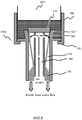
- the water saving aerator 100b shown in this embodiment 3 is a configuration that comprises a decelerator for decelerating the speed of the accelerated water flow jet accelerated by the accelerator and for adjusting the speed of the bubble foam water flow at the lower stream.
- Fig.11 is a schematic view of the water saving aerator 100b in embodiment 3 which does not form part of the present invention but represents background art that is useful for understanding the invention.
- the water saving aerator 100b further comprises the decelerator 140 in addition to the configuration shown in Fig.3 to Fig.5 of embodiment 2.
- the water saving aerator 100b comprises the water flow forming portion 110, the water flow accelerator 111, the ventilation pass 120, the air intake holes 121, the water flow cylinder 130, and the air cavity 131, in addition to the decelerator 140.
- the components such as the water flow forming portion 110, the water flow accelerator 111, the ventilation pass 120, the water flow cylinder 130, and the air cavity 131 are shown in the cross-section view for ease of understanding. These are the solid of revolution shape, but the air intake holes 121 are arrayed around the side surface of the water flow cylinder 130 appropriately, and it is not the solid of revolution shape.
- the water flow forming portion 110, the water flow accelerator 111, the ventilation pass 120, the air intake holes 121, the water flow cylinder 130 and the air cavity 131 are the same as those shown in embodiment 1 and embodiment 2, so the explanation is omitted in this embodiment 3.
- the decelerator 140 can decelerate the velocity of the water flow jet.
- the configuration of the decelerator 140 is not limited.
- the decelerator 140 is a water diffuser.
- the decelerator 140 is a plate shape diffuser object such as a circular frusto-conical shape installed from the center side surface of the water flow cylinder 130 to extend in the peripheral direction. In this configuration, the decelerator 140 is formed as one object united with the water flow cylinder 130 for decreasing the number of parts.
- the decelerator 140 is installed at the position where the water flow jet hits in the water flow cylinder 130.
- the decelerator 140 as a diffuser is installed by adjusting its position and skew for being hit by the water flow jet jetted downstream as bubble foam water flow mixed with the bubbles generated by being accelerated by the water flow accelerator 111 of the water flow forming portion 110 and passing through near the air intake holes 121.
- the decelerator 140 as a diffuser is installed with a certain skew.
- the bubble foam water flow hits and bounds on the decelerator 140 to the peripheral direction, and the speed of the bubble foam water flow is decelerated.
- the bubble foam water flow flushes from the water flow cylinder 130 passing through the gap 141 formed around the periphery of the decelerator 140.
- the decelerator 140 decelerates the accelerated water flow jet
- the configuration of the decelerator 140 is not limited. However, when the processing time for generating the bubble foam water flow, and decelerating the bubble foam water flow becomes long, the number of bubbles disappearing from the bubble foam water becomes large. Therefore, the decelerator 140 is enough for decelerating the speed of the bubble foam water flow appropriately. It is preferable that the processing time is short.
- Fig.12 is a schematic view showing that the bubble foam water flow is generated by flushing the water through the structure shown in Fig.11 in embodiment 3 which does not form part of the present invention but represents background art that is useful for understanding the invention.
- Fig.12 the water flow after turning into the bubble foam water flow is hatched with fine hatching finer than the hatching used for the water flow before turning into the bubble foam water flow.
- the accelerated water flow jet accelerated by the water flow forming portion 110a formed as the gap 114 between the circular truncated cone shape object 112 and the inverted cone shape cylinder 113 is jetted into the air cavity 131, and the air flow jet is injected to the accelerated water flow jet when passing in front of the air intake holes 121, then the water flow jet turns to be the bubble foam water flow.
- the decelerator 140 as the diffuser in the place where the jet of bubble foam water flow hits, and the bubble foam water flow is decelerated by hitting and rebounding from the diffuser.
- the bubble foam water flushes out from the gap between the decelerator 140 as the diffuser and the water flow cylinder 130 without staying in the water saving aerator 100b for too long a time, and as a result, the bubble foam water flow flushes as a gentle stream.
- the water saving aerator can be used as the water saving apparatus and the bubble foam water generator.
- the water saving aerator can be applied to various apparatus not is limited in its use. For example, it can be applied to the water tap not only for commercial use but also for special use such as laboratory use, the special water delivery pipe such as the water delivery pipe for eye-washing water tap in a pool facility and the shower head.
- the water saving aerator according to the present invention can be used as the water saving apparatus and the bubble foam water generator.
- the water saving aerator can be applied to various apparatus not limited for its use. For example, it can be applied to the water tap not only for commercial use but also for special use such as laboratory use, the special water delivery pipe such as the water delivery pipe for eye-washing water tap in a pool facility and the shower head.
Description
- This invention relates to a water saving aerator attached to water delivery devices such as a water tap (including a general water tap and a special purpose water tap for laboratory use) and a shower head for saving the amount of the water flow and aerating the water for generating bubble foam water.
- Bubble foam water is required in many water taps including ordinary homes and in commercial facilities. The impression form use of the bubble foam water in washing is quite gentle. Therefore the bubble foam water is preferably used in washing glasses and the dishes because there is no possibility to a crack or damage the surface of the glasses and the dishes. The bubble foam water has little rebounding even if it hits the surface of the glasses and the dishes in washing, so there is no fear of splashing water around the sink and deteriorating the environment. Therefore, the bubble foam water preferably is used in many water taps not only in ordinary homes but also in the station, in the public facilities, in the laboratory in the research institute, and so on.
- In the prior art, one of the methods for making the bubble foam water is attaching a water saving aerator to the water delivery devices such as a water tap. The water saving aerator in the prior art comprises air intake holes for in taking outer air to the water flow as a basic structure. The outer air is mixed with the water flow via the air intake holes. In addition, the opening of the water delivery devices is covered by the net for cutting the water flow into small pieces. The bubble foam water is generated by mixing the outer air via air intake hole and cutting the water flow by installing several nets to the opening of the water delivery devices for cutting the water flow into small pieces.
DocumentDE1038531 discloses an aerator with a nozzle opening and a hollow cone surrounded by a cylinder, documentUS5826799 relates to a sprinkling head structure in which a liquid quickly passes through a trumpet-shaped water discharging passage to suck air thereinto and documentUS4322292 discloses an aerator capable of aerating at a low flow rate. - The conventional water saving aerator described in the prior art has the following problem. The conventional water saving aerator can generate the bubble foam water including rough bubble, but it cannot generate the bubble foam water including a high quality fine bubble. The conventional water saving aerator supplies the outer air from the air intake holes located on the side wall to the water flow, so the outer air is mixed roughly in to the running water flow by being introduced from the side direction. The size of the involved bubble water is about several millimeters. After being introduced into water flow, the bubble is cut by a net or several nets into small pieces according to the water flow cutting. The bubble foam water is generated in this manner.
- However, the conventional water saving aerator described in the prior art generates the bubble foam water by mixing roughly the outer air into water flow only at the position where the outer air is supplied from the side direction. In addition, the hole of the net is about several millimeters as expected and cannot generate fine bubble smaller than the hole of the net.
- The first approach for generating the fine bubble foam in the conventional water saving aerator is based on increasing the contact area for outer air and water flow. However, it is impossible to increase the contact area in the horizontal direction if the outer air is supplied from the side direction to the water flow. It is possible to increase the contact area in the vertical direction since the length of the contact area with the air becomes large to the extent that the height of the water fall becomes large. Therefore, the amount of the mixing air becomes large. However, the vertical length of the apparatus becomes too large as the bubble foam water saving aerator to be attached to the water tap.
- The second approach for generating the fine bubble foam in the conventional water saving aerator is based on decreasing the mesh size of the net. However, the smaller the mesh size of the net becomes, the larger the resistance to the water flow becomes. The bubble mixed in the bubble foam water larger than the mesh size of the net in the upper stream is difficult to pass through the mesh of the net. If the mesh size of the net reaches the sub-millimeter level, there is a risk that the bubble is blocked and remains inside of the water tap, and that the air intake via the air intake hole is obstructed. In addition, if the mesh size of the net reaches the sub-millimeter level, there is a risk that the suspended particle and contaminant remains and blocks the mesh of the net.
- Therefore, it is an object of the present invention to provide a water saving aerator that can generate the height quality bubble foam water including the fine bubble entirely.
- In order to achieve the above-mentioned object, a water saving aerator with the features of claim 1 is provided.
The present inventor Masaaki TAKANO has studied and conducted the actual experiment repeatedly. He has confirmed that the air becomes fine bubble by being introduced and injected into the accelerated water flow jet at very high speed because the air jet is jetted accelerated by the air pressure generated by the accelerated water jet, and has confirmed that the high quality bubble foam water including fine bubble entirely can be generated. - It is possible to obtain the air cavity in the water flow cylinder by narrowing down the width of the accelerated water jet smaller than that of the width of the water flow cylinder that supplies the jetting space for the accelerated water flow jet. The intake air is jetted via the air intake hole into the air cavity due to the decrease of the air pressure of the air cavity around the air intake hole by jetting out the accelerated water flow jet below in very high speed; and the bubble foam water flow is generated.
- The quality of the bubble included in the bubble foam water flow can be adjusted by modifying the distance and skew between the accelerated water jet and the air intake hole installed in the side surface of the water flow cylinder. Because the air jet is jetted from the air intake hole at high speed, the velocity of the air jet jetted from the air intake hole can be adjusted by the air pressure decrease depending on the positional relationship between the accelerated water jet and the air intake hole, in addition, the velocity of the air jet jetted from the air intake hole can be adjusted by the air pressure decrease depending on the angle relationship between the skew of the accelerated water jet and the installation angle of the air intake hole to the water flow cylinder.
- Therefore, it is preferable that the water saving aerator further comprises an accelerated water flow jet position adjusting mechanism for adjusting the distance between the air intake hole and the accelerated water flow jet jetted into the air cavity.
- It is also preferable that the water saving aerator further comprises an accelerated water flow jet skew adjusting mechanism for adjusting the jet skew of the accelerated water flow jet jetted into the air cavity.
- It is also preferable that the water saving aerator further comprises an air intake hole size adjusting mechanism for adjusting the width of the air intake hole and adjusting the velocity of the air flow jet jetted via the air intake hole, wherein the velocity of the air jetted into the accelerated water flow jet can be adjusted.
- It is also preferable that the water saving aerator can adjust the skew of the ventilation pass to the side surface of the water flow cylinder.
- For example, the skew of the air flow jet to the accelerated water flow jet can be adjusted to be larger than 0 degree and smaller than 90 degrees.
- For example, the skew of the air flow jet to the accelerated water flow jet can be adjusted to be larger than 90 degree and smaller than 180 degrees.
- It is also preferable that the water saving aerator further comprises a ventilation pass skew adjusting mechanism for adjusting the skew of the ventilation pass to the side surface of the water flow and the skew of the air flow jet to the accelerated water flow jet without fixing the skew of the ventilation pass to the side surface of the water flow.
- It is also preferable that the water saving aerator further comprises a water flow cylinder width adjusting mechanism for adjusting the width of the water flow cylinder installed to the water flow forming portion. The adjustment can be done in the attached condition to the water tap; wherein the width of the accelerated water flow jet can be adjusted by operating the water flow cylinder width adjusting mechanism. The mixing status in the bubble foam water flow can be adjusted by adjusting the width of the accelerated water flow jet.
- The water saving aerator of the present invention utilizes the accelerated water flow jet.
- The number of the accelerated water flow jet may as one or more.
- According to the above-mentioned configuration of the invention of the water saving aerator, the air can be injected from the air intake hole and the bubble foam water flow can be generated by decreasing the air pressure around the air intake hole. The air pressure can be adjusted by accelerating the water flow flowing in the water saving aerator by the accelerator.
- According to the above-mentioned configuration of the invention of the water saving aerator, the air cavity can be supplied in the water flow cylinder by narrowing the width of the accelerated water flow jet smaller than that of the water flow cylinder. The accelerated water flow to be jet is jetted into the air cavity, and the air in the air cavity is introduced and be jetted with the accelerated water flow jet below at very high speed. As a result, the air pressure of the air cavity decreases, the air is jetted from the air intake hole and the bubble foam water flow is generated.
- The quality of the bubble included in the bubble foam water flow can be adjusted by adjusting the distance and skew between the accelerated water jet and the air intake hole installed in the side surface of the water flow cylinder. The velocity of the air jet jetted from the air intake hole can be adjusted by the positional relationship between the accelerated water jet and the air intake hole. In addition, the velocity of the air jet jetted from the air intake hole can be adjusted by the angle relationship between the skew of the accelerated water jet and the installation angle of the air intake hole to the water flow cylinder.
-
-
Fig.1 is a schematic view of thewater saving aerator 100 in embodiment 1, not according to the invention, -
Fig.2 is a schematic view showing the bubble foam water flow that is generated by flowing the water through the structure shown inFig.1 . -
Fig.3 is a schematic view of thewater saving aerator 100a of the present invention in embodiment 2. -
Fig.4 is an exploded view showing the waterflow forming portion 110a for ease of understanding. -
Fig.5 is a schematic view showing the bubble foam water flow that is generated by flowing the water through thewater saving aerator 100a of the present invention in embodiment 2. -
Fig.6 is a schematic view of the configuration including the accelerated water flow jet position adjusting mechanism, according to a further embodiment of the invention. -
Fig.7 is a schematic view of the configuration including the accelerated water flow jet skew adjusting mechanism, according to a further embodiment of the invention. -
Fig.8 is a schematic view of a configuration including an air intake hole size adjusting mechanism, not according to the invention. -
Fig.9 is a schematic view of a configuration including a ventilation pass skew adjusting mechanism (part 1), not according to the invention. -
Fig. 10 is a schematic view of the configuration including the ventilation pass skew adjusting mechanism (part 2), not according to the invention. -
Fig.11 is a schematic view of thewater saving aerator 100b in embodiment 3, not according to the invention. -
Fig.12 is a schematic view showing the bubble foam water flow that is generated by flowing the water through the structure in embodiment 3, not according to the invention. - Some embodiments of a water saving aerator according to the present invention are described below with reference to the relevant drawing. Needless to add, the claims of the present invention include but are not limited to the application, configuration, or quantity shown in the following embodiments.
- A schematic view of the
water saving aerator 100 is shown as an example of this embodiment 1. Thewater saving aerator 100 shown in Embodiment 1 can save water and generate the bubble foam water. -
Fig.1 is a schematic view of thewater saving aerator 100 which does not form part of the present invention but represents background art that is useful for understanding the invention. - The
water saving aerator 100 is attached to thewater delivery device 200 such as a water tap and generates the water flow as the bubble foam water flow. - As shown in
Fig.1 , thewater saving aerator 100 includes the waterflow forming portion 110, theventilation pass 120, thewater flow cylinder 130 and theattachment 150. - In
Fig.1 , all components are shown in the cross-section view for ease of understanding. - The water
flow forming portion 110 is the portion for forming the water flow flowing in thewater saving aerator 100. In this configuration, the waterflow forming portion 110 includes thewater flow accelerator 111 for accelerating the water flow. The structure for accelerating the water flow is not limited. The exemplary configuration of thewater flow accelerator 111 shown inFig.1 employs the structure for narrowing the width of the water flow at the accelerating position and the velocity of the water flow becomes large. In this configuration, the upper surface of thewater flow accelerator 111 covers the opening of the water tap. Thewater flow accelerator 111 comprises a small through-hole in the center simply, and the center through-hole works as thewater flow cylinder 130. Thewater flow accelerator 111 accepts the width A of the water flow from theattachment 150 and narrows the width B of the water flow for accelerating the water flow. - In this embodiment, the accelerated water flow is jetted in a pole shape. However, the accelerated water flow is not limited to the pole shape, and the accelerated water flow can be formed as various shape according to the shape of the water
flow forming portion 110 and thewater flow accelerator 111. - The water saving effect can be obtained by employing the above-mentioned
water flow accelerator 111. The water saving effect can be obtained by narrowing the width of the water flow with thewater flow accelerator 111 to be smaller than that of thewater flow cylinder 130. - The
attachment part 150 is a cylinder shape object attached to thewater delivery devices 200 for connecting thewater delivery devices 200 and the waterflow forming portion 110. Theattachment part 150 holds the waterflow forming portion 110 - The internal diameter of the
attachment part 150 is roughly the same as the outer diameter of thewater delivery devices 200. Theattachment part 150 is the device for attaching thewater delivery devices 200. In this configuration, theattachment part 150 comprises screws for fastening to thewater delivery devices 200. The screws in theattachment part 150 and the male screw installed around thewater delivery devices 200 are screwed together, and thewater saving aerator 100 is fastened to thewater delivery devices 200 without leaking water. - It is necessary to use the appropriate figure and size corresponding to that of the opening of the
water delivery devices 200 such as the water tap. However the opening of mostwater delivery devices 200 such as the water tap is standardized according to its use. For example, the water taps used in the public facilities such as the laboratory and the research institute are standardized in the same shape and in the same size. - The
attachment part 150 comprises acylinder 114 with a cone-shape and aflange 151 for supporting the edge of thewater flow cylinder 130 below. The cone-shape cylinder 114 and thewater flow cylinder 130 are suspended below thewater delivery devices 200 via theflange 151 of theattachment 150. - The
ventilation pass 120 is the air pass that leads to the outer air. The air intake holes 121 are installed on the side surface of thewater flow cylinder 130, and the outer air is supplied through the air intake holes 121 from the side surface of thewater flow cylinder 130. In this configuration, the air intake holes 121 are installed on the side surface of thewater flow cylinder 130 where velocity of the water flow becomes large due to thewater flow accelerator 111. The air is supplied through the air intake holes 121 to the accelerated water flow jet jetted by thewater flow accelerator 111, the air is introduced by the force given by the accelerated water flow jet, and the bubble foam water flow is generated. - The air pressure around the air intake holes 121 decreases a lot because of the force given by the accelerated water flow jet to the lower stream, and the air is vacuumed and jetted via the air intake holes from the
ventilation pass 120. The air is injected at the very fast speed to the accelerated water flow jet. - The faster the velocity of the accelerated water flow jet becomes, the faster the velocity of the injected air jet to the accelerated water flow jet becomes, and the mixing of the water and the air is achieved. The air injected from the side surface of the accelerated water flow jet spreads and diffuses inside the water flow, the bubbles become fine and the high quality bubble foam will be obtained.
-
Fig.2 is a schematic view showing that the bubble foam water flow is generated by flowing the water through the structure shown inFig.1 . The water flow, the air flow and the bubble foam water flow to be generated are shown illustratively. - The water flow from the upper stream turns into the bubble foam water flow at the position where the air intake holes 121 are installed because the air flow is jetted and injected into the water flow and the fine bubble are mixed.
- If the velocity of the water flow becomes larger by narrowing the width of the water flow by operating the
water flow accelerator 111, the air pressure around the air intake holes 121 decreases more and the velocity of the injected air flow jet becomes large. As a result, the amount of the bubbles injected to the water flow becomes large and the bubble size becomes finer. - According to the
water saving aerator 100 of the embodiment 1, high quality bubble foam water flow can be obtained by injecting the air flow jet from the ventilation pass by decreasing the air pressure around the air intake holes by accelerating the water flow jet by the water flow accelerator as shown above. - The water saving aerator employing the air cavity is shown as an example of this embodiment 2.
- The
water saving aerator 100a includes theair cavity 131 in thewater flow cylinder 130. In this configuration, the width of the accelerated water flow jet is narrowed to be smaller than that of thewater flow cylinder 130. The air pressure around the air intake holes facing theair cavity 131 is decreased by jetting the accelerated water flow jet into the air cavity, and the air is vacuumed and jetted through the air intake holes 121 to generate the bubble foam water flow. -
Fig.3 is a schematic view of thewater saving aerator 100a of the present invention in embodiment 2. The same asFig.1 , all components are shown in cross-section for ease of understanding. Actually, thewater saving aerator 100a is a solid of revolution shape. - As shown in
Fig.3 , the waterflow forming portion 110a is installed beneath theattachment part 150, and the accelerated water flow jet is jetted by thewater flow accelerator 111a. - In the configuration shown in
Fig.3 , thecone shape object 112 faces the invertedcone shape cylinder 113 in vertical direction. These are not contacted directly; these are facing with acertain gap 114. Thegap 114 is formed between the outer surface of thecone shape object 112 and the internal surface of the invertedcone shape cylinder 113. Thisgap 114 is used as the water flow forming portion in thewater saving aerator 100a. - In
Fig.3 , thecone shape object 112 and theventilation pass 120 are shown above the invertedcone shape cylinder 113. However, thecone shape object 112 and theventilation pass 120 are supported by the supporting object (not shown in Figure). - The same as embodiment 1, the
attachment part 150 is a cylinder shape object attached to thewater delivery devices 200 for connecting thewater delivery devices 200 and the waterflow forming portion 110a. Theattachment part 150 holds the waterflow forming portion 110a. -
Fig.4 is an exploded view showing the waterflow forming portion 110a for ease of understanding. -
Fig.4 shows in a cross-sectional view. Most components are the solid of revolution shape, but the air intake holes 121 are not the solid of revolution shape. Pluralities of the air intake holes 121 are formed in the side surface of the water flow cylinder to theventilation pass 120. Thewater flow accelerator 111a of the waterflow forming portion 110a is formed by the combination of the outer surface of thecone shape object 112 and the internal surface of the invertedcone shape cylinder 113, and thegap 114 between these two objects works as the water flow of thiswater saving aerator 100a. -
Fig.4 (a) is a schematic view showing thecone shape object 112 and theventilation pass 120. Theventilation pass 120 is a pipe shape pass. The air intake holes 121 are the holes on the side surface of theventilation pass 120. -
Fig.4 (b) is a schematic view showing the invertedcone shape cylinder 113 and thewater flow cylinder 130. Thewater flow cylinder 130 is a cylinder shape object. - The water flow is accelerated when passing this
gap 114 because the width of thegap 114 is smaller than that of theattachment part 150. - In this configuration, the accelerated water flow jet formed by the water
flow forming portion 110a is jetted as the cylindrical shape, in other words, a belt like round shape. The shape of the accelerated water flow jet is not limited to such a cylindrical shape, and the accelerated water flow can be formed as various shape according to the shape of the waterflow forming portion 110a and thewater flow accelerator 111a. - In this configuration, as shown in
Fig.3 , a part of the space in thewater flow cylinder 130 beneath thewater flow accelerator 111a is used as theair cavity 131 always filled with air even if the water is running through thewater saving aerator 100a. In this configuration, the width A of thewater flow cylinder 130 beneath thewater flow accelerator 111a is larger than the width B of the accelerated water flow jet, and the accelerated water flow jet can be jetted from thewater flow accelerator 111a into the air contained in theair cavity 131 at high speed. -
Fig.5 is a schematic view showing the bubble foam water flow that is generated by flowing the water through thewater saving aerator 100a of the present invention in embodiment 2. - The water is accepted via the
attachment 150 and led to thegap 114 of the waterflow forming portion 110a, and the water flow is accelerated when passing thegap 114. The accelerated water flow is jetted into theair cavity 131 filled with the air. In this configuration, the width of thewater flow cylinder 130 is larger than that of the accelerated water flow, so the air cavity can keep on containing the air. There are air intake holes 121 beneath thegap 114. - The accelerated water flow jet is jetted into the
air cavity 131 filled with the air, and the accelerated water flow jet goes downstream, introducing the air in the air cavity. A part of the air in theair cavity 131 is flushed away, and the air pressure in theair cavity 131 is decreased. The air intake holes 121 are installed on the side surface of theair cavity 131, and the air pressure decrease occurs around the air intake holes 121, so the air pressure around the air intake holes 121 is decreased. The air intake holes 121 are connected to the outer air through theventilation pass 120. The air is vacuumed from the outer air through theventilation pass 120 into the air cavity at high speed. The velocity of the air flow jet depends on the diameter of the air intake holes 121, in this configuration, the velocity of the air flow jet jetted from the air intake holes 121 becomes large if the air is vacuumed into the air cavity at high speed. In this configuration, the accelerated water flow jet is jetted near the air intake holes 121, so the air flow jet is injected to the accelerated water flow jet. - The
air cavity 131 is filled with the air, and the accelerated water flow jet is jetted into the air contained in the air cavity. In addition, the air flow jet is jetted via the air intake holes 121 from the side direction, the air is injected into the accelerated water flow jet and bubbles are diffused entirely. As a result, the high quality bubble foam water flow is generated. - In
Fig.5 , the water flow after turning into the bubble foam water flow is hatched with fine hatching finer than the hatching used for the water flow before turning into the bubble foam water flow. - The configuration shown above is the basic structure of the
water saving aerator 100a employing theair cavity 131. - Next, the adjustments on various conditions such as the distance between the accelerated water flow jet jetted into the
air cavity 131 and the air intake holes 121, the angle of the accelerated water flow jetted into theair cavity 131, the width of the air intake holes and the installation angle of the air intake holes (the angle of the air flow jet jetted from the air intake holes 121 to the accelerated water flow jet) are described. - First, the configuration including the accelerated water flow jet position adjusting mechanism is described. It is used for adjusting the distance between the accelerated water flow jet jetted into the
air cavity 131 and the air intake holes 121. -
Fig.6 is a schematic view of the configuration including the accelerated water flow jet position adjusting mechanism. - In
Fig.6 , the water flow after turning into the bubble foam water flow is hatched with fine hatching finer than the hatching used for the water flow before turning into the bubble foam water flow. - The accelerated water flow jet position adjusting mechanism is formed in the water
flow forming portion 110a. It can adjust the position of the accelerated water flow jet to be formed by thewater flow accelerator 111a, as a result, the distance between the accelerated water flow jet and the air intake holes 121 is adjusted. The method for adjusting the position of the accelerated water flow jet to be formed and adjusting the distance between the accelerated water flow jet and the air intake holes 121 is not limited, but in this configuration, the accelerated water flow jet position adjusting mechanism can adjust the position of the waterflow forming portion 110a and thewater flow accelerator 111a. InFig.6 , the detailed structure of the accelerated water flow jet position adjusting mechanism is not shown, but it can move the object forming thegap 114 to the center position and to the peripheral position as shown by the arrows. - If the accelerated water flow jet position adjusting mechanism adjusts the position of the object forming the
gap 114 from that shown inFig.6 (a) to Fig.6 (b) , the position of the accelerated water flow jet is shifted in a center direction (near the air intake hole 121), and the distance between the accelerated water flow jet and theair intake hole 121 becomes smaller. If the accelerated water flow jet position adjusting mechanism adjusts the position of the object forming thegap 114 from that shown inFig.6 (b) to Fig.6 (a) , the position of the accelerated water flow jet is shifted in a peripheral direction (far from the air intake hole 121), and the distance between the accelerated water flow jet and theair intake hole 121 becomes larger. - When the air is jetted from the air intake holes 121 into the
air cavity 131, the air contained in theair cavity 131 works as a resistance, so if the distance to the accelerated water flow jet becomes long, the velocity of the air flow jet decreases because of the resistance. Therefore, the velocity and the amount of the air flow jet in the air cavity can be controlled by adjusting the distance to the accelerated water flow jet. - As shown in
Fig.6 (a) , if the forming position of the accelerated water flow jet is shifted in a center direction and the distance to the air intake holes 121 becomes smaller, the velocity and the amount of the air flow jet from the air intake holes 121 increases and the amount of the bubbles mixed into the accelerated water flow jet becomes larger. - As shown in
Fig.6 (b) , if the forming position of the accelerated water flow jet is shifted in a peripheral direction and the distance to the air intake holes 121 becomes larger, the velocity and the amount of the air flow jet from the air intake holes 121 decreases and the amount of the bubble mixed into the accelerated water flow jet becomes smaller. - As shown above, the amount of bubble can be controlled by adjusting the forming position of the accelerated water flow jet with the accelerated water flow jet position adjusting mechanism.
- The amount and the size of the bubbles mixed into the accelerated water flow jet depend on other conditions such as the amount of the water in the accelerated water flow jet, the velocity of the accelerated water flow jet, the width and the height of the
air cavity 131 and the width of the air intake holes 121. Taking these conditions into account, the forming position of the accelerated water flow jet is adjusted with the accelerated water flow jet position adjusting mechanism. As a result, the amount and the size of the bubbles mixed into the accelerated water flow jet can be adjusted. - Next, the configuration including the accelerated water flow jet skew adjusting mechanism for adjusting the skew of the accelerated water flow jet jetted into the
air cavity 131 is described. -
Fig.7 is a schematic view of the configuration including the accelerated water flow jet skew adjusting mechanism. - In
Fig.7 , the water flow after turning into the bubble foam water flow is hatched with fine hatching finer than the hatching used for the water flow before turning into the bubble foam water flow. - The accelerated water flow jet skew adjusting mechanism is formed in the water
flow forming portion 110a. It can adjust the skew of the accelerated water flow jet jetted by thewater flow accelerator 111a. As a result, the distance and the skew relative to the air intake holes 121 can be adjusted. The methods for adjusting the skew of the accelerated water flow jet and the method for adjusting the distance to the air intake holes 121 are not limited, but in this configuration, the accelerated water flow jet skew adjusting mechanism can adjust the skew of the installation of the waterflow forming portion 110a and thewater flow accelerator 111a. InFig.7 , the detailed structure of the accelerated water flow jet skew adjusting mechanism is not shown, but it can move the object forming the air intake holes 121 up and down and it can change the skew of the object forming thegap 114 as shown by the arrows. - If the accelerated water flow jet skew adjusting mechanism adjusts the skew of the object forming the
gap 114 from that shown inFig.7 (a) to Fig.7 (b) , the position of the accelerated water flow jet is shifted in a center direction (near the air intake hole 121), and the distance between the accelerated water flow jet and theair intake hole 121 becomes smaller. If the accelerated water flow jet skew adjusting mechanism adjusts the position of the object forming thegap 114 from that shown inFig.7 (b) to Fig.7 (a), the position of the accelerated water flow jet is shifted in a peripheral direction (far from the air intake hole 121), and the distance between the accelerated water flow jet and theair intake hole 121 becomes larger. - When the air is jetted from the air intake holes 121 into the
air cavity 131, the air contained in theair cavity 131 works as a resistance, so if the distance to the accelerated water flow jet becomes long, the velocity of the air flow jet decreases because of the resistance. Therefore, the velocity and the amount of the air flow jet in the air cavity can be controlled by adjusting the moving distance of the accelerated water flow jet. - As shown in
Fig.7 (a) , if the skew of the accelerated water flow jet shifted in a center direction and the distance to the air intake holes 121 become smaller, the velocity and the amount of the air flow jet from the air intake holes 121 increase and the amount of the bubbles mixed into the accelerated water flow jet becomes larger. - As shown in
Fig.7 (b) , if the skew of the accelerated water flow jet shifted in a peripheral direction and the distance to the air intake holes 121 becomes larger, the velocity and the amount of the air flow jet from the air intake holes 121 decrease and the amount of the bubbles mixed into the accelerated water flow jet becomes smaller. - As shown above, the amount of bubble can be controlled by adjusting the skew of the accelerated water flow jet with the accelerated water flow jet skew adjusting mechanism.
- The amount and the size of the bubble mixed into the accelerated water flow jet depend on other conditions such as the amount of the water in the accelerated water flow jet, the velocity of the accelerated water flow jet, the width and the height of the
air cavity 131 and the width of the air intake holes 121. Taking these conditions into account, the skew of the accelerated water flow jet is adjusted with the accelerated water flow jet skew adjusting mechanism. As a result, the amount and the size of the bubble mixed into the accelerated water flow jet can be adjusted. - Next, the configuration including the air intake hole size adjusting mechanism for adjusting the width of the air intake holes 121 and adjusting the velocity of the air flow jet jetted via the air intake holes 121 is described.
-
Fig.8 is a schematic view of a configuration including an air intake hole size adjusting mechanism. In this configuration, which does not form part of the present invention but represents background art that is useful for understanding the invention, the width of the air intake holes 121 can be adjusted. - In
Fig.8 , the water flow after turning into the bubble foam water flow is hatched with fine hatching finer than the hatching used for the water flow before turning into the bubble foam water flow. - The air intake hole size adjusting mechanism can adjust the width of the air intake hole and adjust the velocity of the air flow jet jetted into the air cavity.
- The methods for adjusting the width of the air intake holes 121 are not limited, but in this configuration, the air intake hole size adjusting mechanism can adjust the relative distance between the objects that form the air intake holes 121, and as a result, it can adjust the width of the gap between these objects. In
Fig.8 , the detailed structure of the air intake hole size adjusting mechanism is not shown, but it can move the objects forming the air intake holes 121 up and down as shown by the arrows. - If the air intake hole size adjusting mechanism adjusts the width of the air intake holes as shown in
Fig.8 (a) to Fig.8 (b) , the width of the air intake holes 121 become large, and the air pass becomes large. Therefore, the velocity of the vacuumed air jet decreases when vacuuming the air into theair cavity 131 if the amount of the air to be vacuumed is the same. - If the air intake hole size adjusting mechanism adjusts the width of the air intake holes as shown in
Fig.8 (b) to Fig.8 (a) , the width of the air intake holes 121 becomes narrow, and the air pass becomes narrow. Therefore, the velocity of the vacuumed air jet increases when vacuuming the air into theair cavity 131 if the amount of the air to be vacuumed is the same. - The velocity of the air flow jet jetted from the air intake holes 121 into the air cavity shown in
Fig.8 (a) becomes faster than that shown inFig.8 (b) . As a result, the velocity and the amount of the air flow jet injected into the accelerated water flow jet becomes large, and the bubble mixed in the accelerated water flow jet becomes large. - The velocity of the air flow jet jetted from the air intake holes 121 into the air cavity shown in
Fig.8 (b) becomes slower that shown inFig.8 (a) . As a result, the velocity and the amount of the air flow jet injected into the accelerated water flow jet become small, and the bubble mixed in the accelerated water flow jet becomes small. - As shown above, the amount of bubbles can be controlled by adjusting the width of the air intake holes 121 with the air intake hole size adjusting mechanism.
- The amount and the size of the bubble mixed into the accelerated water flow jet depend on other conditions such as the amount of the water in the accelerated water flow jet, the velocity of the accelerated water flow jet, the width and the height of the
air cavity 131 and the width of the air intake holes 121. Taking these conditions into account, the width of air intake holes 121 is adjusted with the air intake hole size adjusting mechanism, and as a result, the amount and the size of the bubble mixed into the accelerated water flow jet can be adjusted. - Next, the configuration including the ventilation pass skew adjusting mechanism for adjusting the skew of the
ventilation pass 120 relative to the side wall of the water flow cylinder is described. -
Fig.9 is a schematic view of a configuration including a ventilation pass skew adjusting mechanism. In this configuration, which does not form part of the present invention but represents background art that is useful for understanding the invention, the installation skew of the air intake holes 121 can be adjustable. - In
Fig.9 , the water flow after turning to the bubble foam water flow is hatched with fine hatching finer than the hatching hatched to the water flow before turning to the bubble foam water flow. - The ventilation pass skew adjusting mechanism can adjust the skew of the
ventilation pass 120 to the side surface of thewater flow cylinder 130 and adjust the skew of the air flow jet to theair cavity 131. - The method for adjusting the installation skew of the
ventilation pass 120 to the side surface of thewater flow cylinder 130 is not limited. In this configuration, the ventilation pass skew adjusting mechanism can adjust the relative skew of the objects forming theventilation pass 120. - In
Fig.9 (a) , the skew of theventilation pass 120 relative to the side surface of thewater flow cylinder 130 and the accelerated water flow jet is adjusted to be 90 degrees. The air flow jetted from the air intake holes 121 is injected to the accelerated water flow at the right angle. - In
Fig.9 (b) , the skew of theventilation pass 120 to the side surface of thewater flow cylinder 130 and the accelerated water flow jet is adjusted to be larger than 0 degree and smaller than 90 degrees (it is 45 degrees in this configuration). The air flow jetted from the air intake holes 121 is injected into the accelerated water flow at 45 degrees. - In
Fig.10 , which does not form part of the present invention but represents background art that is useful for understanding the invention, the skew of theventilation pass 120 relative to the side surface of thewater flow cylinder 130 and the accelerated water flow jet is adjusted to be larger than 90 degree and smaller than 180 degrees (it is 135 degrees in this configuration). The air flow jetted from the air intake holes 121 is injected into the accelerated water flow at 135 degrees. - As shown above, the velocity and the skew of the air flow injected to the accelerated water flow jet can be adjusted by adjusting the skew of the air flow jet. As a result, the amount of the bubble and the size of the bubble mixed in the accelerated water flow jet can be controlled.
- The amount and the size of the bubble mixed into the accelerated water flow jet depend on other conditions such as the amount of the water in the accelerated water flow jet, the velocity of the accelerated water flow jet, the width and the height of the
air cavity 131 and the width of the air intake holes 121. Taking these conditions into account, the skew ofventilation pass 120 is adjusted with the ventilation pass skew adjusting mechanism, and as a result, the amount and the size of the bubble mixed into the accelerated water flow jet can be adjusted. - The
water saving aerator 100b shown in this embodiment 3 is a configuration that comprises a decelerator for decelerating the speed of the accelerated water flow jet accelerated by the accelerator and for adjusting the speed of the bubble foam water flow at the lower stream. -
Fig.11 is a schematic view of thewater saving aerator 100b in embodiment 3 which does not form part of the present invention but represents background art that is useful for understanding the invention. In this configuration, thewater saving aerator 100b further comprises thedecelerator 140 in addition to the configuration shown inFig.3 to Fig.5 of embodiment 2. - The
water saving aerator 100b comprises the waterflow forming portion 110, thewater flow accelerator 111, theventilation pass 120, the air intake holes 121, thewater flow cylinder 130, and theair cavity 131, in addition to thedecelerator 140. InFig.11 , the components such as the waterflow forming portion 110, thewater flow accelerator 111, theventilation pass 120, thewater flow cylinder 130, and theair cavity 131 are shown in the cross-section view for ease of understanding. These are the solid of revolution shape, but the air intake holes 121 are arrayed around the side surface of thewater flow cylinder 130 appropriately, and it is not the solid of revolution shape. - In this embodiment 3, the water
flow forming portion 110, thewater flow accelerator 111, theventilation pass 120, the air intake holes 121, thewater flow cylinder 130 and theair cavity 131 are the same as those shown in embodiment 1 and embodiment 2, so the explanation is omitted in this embodiment 3. - The
decelerator 140 can decelerate the velocity of the water flow jet. The configuration of thedecelerator 140 is not limited. In this embodiment, thedecelerator 140 is a water diffuser. - The
decelerator 140 is a plate shape diffuser object such as a circular frusto-conical shape installed from the center side surface of thewater flow cylinder 130 to extend in the peripheral direction. In this configuration, thedecelerator 140 is formed as one object united with thewater flow cylinder 130 for decreasing the number of parts. - In this configuration, the
decelerator 140 is installed at the position where the water flow jet hits in thewater flow cylinder 130. Thedecelerator 140 as a diffuser is installed by adjusting its position and skew for being hit by the water flow jet jetted downstream as bubble foam water flow mixed with the bubbles generated by being accelerated by thewater flow accelerator 111 of the waterflow forming portion 110 and passing through near the air intake holes 121. In this configuration, thedecelerator 140 as a diffuser is installed with a certain skew. The bubble foam water flow hits and bounds on thedecelerator 140 to the peripheral direction, and the speed of the bubble foam water flow is decelerated. The bubble foam water flow flushes from thewater flow cylinder 130 passing through the gap 141 formed around the periphery of thedecelerator 140. - The
decelerator 140 decelerates the accelerated water flow jet, the configuration of thedecelerator 140 is not limited. However, when the processing time for generating the bubble foam water flow, and decelerating the bubble foam water flow becomes long, the number of bubbles disappearing from the bubble foam water becomes large. Therefore, thedecelerator 140 is enough for decelerating the speed of the bubble foam water flow appropriately. It is preferable that the processing time is short. -
Fig.12 is a schematic view showing that the bubble foam water flow is generated by flushing the water through the structure shown inFig.11 in embodiment 3 which does not form part of the present invention but represents background art that is useful for understanding the invention. - In
Fig.12 , the water flow after turning into the bubble foam water flow is hatched with fine hatching finer than the hatching used for the water flow before turning into the bubble foam water flow. - As shown in
Fig.5 described in embodiment 2, the accelerated water flow jet accelerated by the waterflow forming portion 110a formed as thegap 114 between the circular truncatedcone shape object 112 and the invertedcone shape cylinder 113 is jetted into theair cavity 131, and the air flow jet is injected to the accelerated water flow jet when passing in front of the air intake holes 121, then the water flow jet turns to be the bubble foam water flow. In this configuration shown in embodiment 3, there is the decelerator 140 as the diffuser in the place where the jet of bubble foam water flow hits, and the bubble foam water flow is decelerated by hitting and rebounding from the diffuser. In this configuration, the bubble foam water flushes out from the gap between the decelerator 140 as the diffuser and thewater flow cylinder 130 without staying in thewater saving aerator 100b for too long a time, and as a result, the bubble foam water flow flushes as a gentle stream. - According to the
water saving aerator 100b of the embodiment 3, high quality bubble foam water flow can be obtained. - As shown above, the water saving aerator can be used as the water saving apparatus and the bubble foam water generator. The water saving aerator can be applied to various apparatus not is limited in its use. For example, it can be applied to the water tap not only for commercial use but also for special use such as laboratory use, the special water delivery pipe such as the water delivery pipe for eye-washing water tap in a pool facility and the shower head.
- While some preferable embodiments of the water saving aerator according to the present invention are described above, it should be understood that various changes are possible, without deviating from the technical scope according to the present invention. Therefore, the technical scope according to the present invention is limited only by the claims attached.
- The water saving aerator according to the present invention can be used as the water saving apparatus and the bubble foam water generator. The water saving aerator can be applied to various apparatus not limited for its use. For example, it can be applied to the water tap not only for commercial use but also for special use such as laboratory use, the special water delivery pipe such as the water delivery pipe for eye-washing water tap in a pool facility and the shower head.
Claims (9)
- A water saving aerator (100a) adapted to be attached to a water tap for generating bubble foam water and flowing the bubble foam water, comprising;a water flow forming portion (110a) for forming a water flow through the water saving aerator (100a);a water flow accelerator (111a) for accelerating the water flow supplied from the water flow forming portion (110a) by narrowing its width and jetting an accelerated water flow jet downward;an inner cylindrical pipe provided with an air intake hole (121); andan outer cylindrical pipe enclosing the inner cylindrical pipe, the outer cylindrical pipe being arranged below the water flow forming portion (110a);wherein a space between the inner cylindrical pipe and the outer cylindrical pipe constitutes a water flow cylinder (130) through which the water accelerated by the water flow accelerator (111a) flows;wherein the water flow accelerator (111a) is configured to flow the accelerated water flow jet obliquely downward to hit an outer cylindrical surface of the water flow cylinder (130) and to reflect the water flow jet obliquely downward for diffusing the width of the accelerated water jet to cover the width of the water flow cylinder (130);wherein the air intake hole (121) is provided in the inner cylindrical pipe below and adjacent the water flow forming portion (110a);wherein an air cavity (131) is provided in an inner space of the water flow cylinder (130), wherein the air cavity (131) is always filled with air even when water flushes into it;wherein a width of the accelerated water flow jet is narrower than that of the water flow cylinder (130);wherein a ventilation pass (120) for supplying outer air to the air cavity (131) via the air intake hole (121) is provided inside the inner cylindrical pipe; andwherein the accelerated water flow jet accelerated by the water flow accelerator (111a) is jetted into the air contained in the air cavity (131) supplied from the air intake hole (121), the bubble foam water flow is generated by injecting the air from the air intake hole (121) into the water flow with the force generated by the air pressure decrease by the accelerated water flow jet.
- A water saving aerator according to claim 1, further comprising:
an accelerated water flow jet position adjusting mechanism for adjusting a distance between the air intake hole (121) and the accelerated water flow jet jetted into the air cavity. - A water saving aerator according to claim 1, further comprising:
an accelerated water flow jet skew adjusting mechanism for adjusting a jet skew of the accelerated water flow jet jetted into the air cavity (131). - A water saving aerator according to claim 1, further comprising:
an air intake hole size adjusting mechanism for adjusting a width of the air intake hole (121) and adjusting the velocity of the air flow jet jetted via the air intake hole (121), wherein the velocity of the air jetted into the accelerated water flow jet can be adjusted. - A water saving aerator according to any one of claims 1 to 4, in which a skew of the ventilation pass (120) relative to the side surface of the water flow cylinder is adjusted such that a skew of the air flow jet to the accelerated water flow jet becomes larger than 0 degree and smaller than 90 degrees.
- A water saving aerator according to any one of claims 1 to 4, in which a skew of the ventilation pass (120) relative to the side surface of the water flow cylinder is adjusted such that a skew of the air flow jet to the accelerated water flow jet becomes larger than 90 degree and smaller than 180 degrees.
- A water saving aerator according to any one of claims 1 to 4, further comprising:
a ventilation pass skew adjusting mechanism for adjusting a skew of the ventilation pass relative to the side surface of the water flow and a skew of the air flow jet to the accelerated water flow jet. - A water saving aerator according to any one of claims 1 to 7, further comprising:
a water flow cylinder width adjusting mechanism for adjusting the width of the water flow cylinder (130) installed to the water flow forming portion (110a), the adjustment being capable of being done in the attached condition to the water tap; wherein the width of the accelerated water flow jet can be adjusted by operating the water flow cylinder width adjusting mechanism. - A water saving aerator according to any one of claims 1 to 8, in which there are plural accelerated water flow jets generated by the water flow forming portion (110a) and the accelerator (111a).
Priority Applications (3)
| Application Number | Priority Date | Filing Date | Title |
|---|---|---|---|
| PL09842291T PL2412877T3 (en) | 2009-03-26 | 2009-03-26 | Foamed-water generating plug |
| PT09842291T PT2412877T (en) | 2009-03-26 | 2009-03-26 | Foamed-water generating plug |
| HUE09842291A HUE043817T2 (en) | 2009-03-26 | 2009-03-26 | Foamed-water generating plug |
Applications Claiming Priority (1)
| Application Number | Priority Date | Filing Date | Title |
|---|---|---|---|
| PCT/JP2009/056852 WO2010109680A1 (en) | 2009-03-26 | 2009-03-26 | Foamed-water generating plug |
Publications (3)
| Publication Number | Publication Date |
|---|---|
| EP2412877A1 EP2412877A1 (en) | 2012-02-01 |
| EP2412877A4 EP2412877A4 (en) | 2014-11-19 |
| EP2412877B1 true EP2412877B1 (en) | 2018-12-12 |
Family
ID=42780388
Family Applications (1)
| Application Number | Title | Priority Date | Filing Date |
|---|---|---|---|
| EP09842291.8A Active EP2412877B1 (en) | 2009-03-26 | 2009-03-26 | Foamed-water generating plug |
Country Status (12)
| Country | Link |
|---|---|
| US (1) | US9297153B2 (en) |
| EP (1) | EP2412877B1 (en) |
| JP (1) | JP4860781B2 (en) |
| KR (1) | KR101284781B1 (en) |
| CN (1) | CN102405321B (en) |
| DK (1) | DK2412877T3 (en) |
| ES (1) | ES2715074T3 (en) |
| HU (1) | HUE043817T2 (en) |
| PL (1) | PL2412877T3 (en) |
| PT (1) | PT2412877T (en) |
| SG (1) | SG174924A1 (en) |
| WO (1) | WO2010109680A1 (en) |
Families Citing this family (4)
| Publication number | Priority date | Publication date | Assignee | Title |
|---|---|---|---|---|
| JP5961733B1 (en) * | 2015-07-30 | 2016-08-02 | 雅彰 高野 | Pulsating fluid or intermittent fluid generator |
| US10184233B2 (en) * | 2016-08-28 | 2019-01-22 | Gary Wu | Aerator with LED |
| US10898909B2 (en) * | 2017-10-25 | 2021-01-26 | Pioneer Industries, Inc. | Water pressure boosting device |
| WO2019160898A1 (en) | 2018-02-13 | 2019-08-22 | Tan Yung Chieh | Liquid saving device |
Family Cites Families (22)
| Publication number | Priority date | Publication date | Assignee | Title |
|---|---|---|---|---|
| GB698691A (en) * | 1949-11-29 | 1953-10-21 | Elie Prodromos Aghnides | Mixing devices for liquid and gas |
| DE1038531B (en) * | 1953-08-05 | 1958-09-11 | Rothmayr & Co | End of phase |
| US3334818A (en) * | 1965-09-22 | 1967-08-08 | Alfred M Moen | Swivel spray aerators |
| US3712548A (en) * | 1970-08-20 | 1973-01-23 | E Aghnides | Water aerator |
| JPS5058553A (en) * | 1973-09-21 | 1975-05-21 | ||
| JPS51134Y2 (en) | 1973-09-25 | 1976-01-06 | ||
| US4153204A (en) | 1975-08-08 | 1979-05-08 | Aghnides Elie P | Aerator with metal casing having inner plastic elements moldable in one piece |
| US4322292A (en) * | 1981-01-02 | 1982-03-30 | Rjd | Aerator |
| US4484710A (en) * | 1983-03-11 | 1984-11-27 | The United States Of America As Represented By The Secretary Of The Army | Fire suppressant nozzle |
| US4869103A (en) * | 1988-06-03 | 1989-09-26 | Jerman James K | Water flow measuring and dispersing device |
| JPH038940A (en) | 1989-06-06 | 1991-01-16 | Toto Ltd | Foam-ejecting spout |
| JPH0679684B2 (en) | 1989-11-21 | 1994-10-12 | 東陶機器株式会社 | Foam spout |
| US5143295A (en) | 1989-11-21 | 1992-09-01 | Toto Ltd. | Bubbly water outlet device |
| JPH047051A (en) | 1990-04-23 | 1992-01-10 | Toto Ltd | Water discharge head |
| US5826799A (en) * | 1996-12-03 | 1998-10-27 | Hsieh; Paul | Sprinkling head structure |
| KR100243787B1 (en) * | 1997-03-31 | 2000-02-01 | 전주범 | Apparatus for generating air bubble |
| IT1293138B1 (en) * | 1997-06-03 | 1999-02-12 | Gevipi Ag | DEVICE FOR THE AERATION OF A MULTIPLE JET SHOWER. |
| CN2705681Y (en) * | 2004-01-20 | 2005-06-22 | 招丽恩 | Water saving nozzle core |
| JP4736672B2 (en) | 2005-09-27 | 2011-07-27 | パナソニック電工株式会社 | Shower equipment |
| US7611070B2 (en) * | 2006-02-28 | 2009-11-03 | Paoluccio John J | Aspirating scented oxygen enriched faucet and shower head |
| JP5054434B2 (en) | 2007-06-04 | 2012-10-24 | 嘉樹 建守 | Water-saving member and water-saving device using the same |
| HUE047325T2 (en) * | 2008-10-31 | 2020-04-28 | Masaaki Takano | Water saving disc |
-
2009
- 2009-03-26 KR KR1020117021877A patent/KR101284781B1/en active IP Right Grant
- 2009-03-26 HU HUE09842291A patent/HUE043817T2/en unknown
- 2009-03-26 PT PT09842291T patent/PT2412877T/en unknown
- 2009-03-26 ES ES09842291T patent/ES2715074T3/en active Active
- 2009-03-26 CN CN200980158172.9A patent/CN102405321B/en active Active
- 2009-03-26 JP JP2011505794A patent/JP4860781B2/en active Active
- 2009-03-26 SG SG2011069770A patent/SG174924A1/en unknown
- 2009-03-26 DK DK09842291.8T patent/DK2412877T3/en active
- 2009-03-26 WO PCT/JP2009/056852 patent/WO2010109680A1/en active Application Filing
- 2009-03-26 PL PL09842291T patent/PL2412877T3/en unknown
- 2009-03-26 EP EP09842291.8A patent/EP2412877B1/en active Active
- 2009-03-26 US US13/260,034 patent/US9297153B2/en active Active
Non-Patent Citations (1)
| Title |
|---|
| None * |
Also Published As
| Publication number | Publication date |
|---|---|
| DK2412877T3 (en) | 2019-04-01 |
| ES2715074T3 (en) | 2019-05-31 |
| KR20120024536A (en) | 2012-03-14 |
| CN102405321A (en) | 2012-04-04 |
| KR101284781B1 (en) | 2013-07-17 |
| PL2412877T3 (en) | 2019-07-31 |
| JP4860781B2 (en) | 2012-01-25 |
| US20120024984A1 (en) | 2012-02-02 |
| WO2010109680A1 (en) | 2010-09-30 |
| CN102405321B (en) | 2015-05-20 |
| SG174924A1 (en) | 2011-11-28 |
| EP2412877A4 (en) | 2014-11-19 |
| JPWO2010109680A1 (en) | 2012-09-27 |
| US9297153B2 (en) | 2016-03-29 |
| HUE043817T2 (en) | 2019-09-30 |
| PT2412877T (en) | 2019-03-22 |
| EP2412877A1 (en) | 2012-02-01 |
Similar Documents
| Publication | Publication Date | Title |
|---|---|---|
| FI113748B (en) | Flotation chamber with an injector | |
| EP2412877B1 (en) | Foamed-water generating plug | |
| EP2345765B1 (en) | Water saving disc | |
| JP2021504133A (en) | Micro bubble generator | |
| KR20130041831A (en) | Bubble generator | |
| JP2008303616A (en) | Rim spout structure of water closet | |
| KR102374199B1 (en) | Apparatus to prevent urine spattering for men | |
| CA2819573C (en) | Foamed-water saving aerator | |
| JP2012207492A (en) | Water discharging device | |
| JP2007056559A (en) | Shower head | |
| JP4919286B2 (en) | Microbubble generator | |
| CN107906252A (en) | A kind of Anti-blockage water-saving sparger | |
| JP2010142336A (en) | Shower device | |
| CN207740545U (en) | A kind of Anti-blockage water-saving sparger | |
| JP2002275969A (en) | Foamed water discharging device | |
| JP2008149294A (en) | Microbubble generater | |
| JPWO2012033128A1 (en) | Water saving top | |
| JP7343100B2 (en) | Micro bubble generator | |
| JP5748183B2 (en) | Shower equipment | |
| JP6315247B2 (en) | Water discharge device | |
| JP2010264445A (en) | Minute air bubble generator | |
| KR20180060301A (en) | the improved air induction type nozzle improving air suction function | |
| JP2008212769A (en) | Aerator | |
| JP2005058924A (en) | Bubble generating nozzle, and bubble-generating apparatus equipped with the same | |
| JPH0363333A (en) | Foam spout |
Legal Events
| Date | Code | Title | Description |
|---|---|---|---|
| PUAI | Public reference made under article 153(3) epc to a published international application that has entered the european phase |
Free format text: ORIGINAL CODE: 0009012 |
|
| 17P | Request for examination filed |
Effective date: 20111024 |
|
| AK | Designated contracting states |
Kind code of ref document: A1 Designated state(s): AT BE BG CH CY CZ DE DK EE ES FI FR GB GR HR HU IE IS IT LI LT LU LV MC MK MT NL NO PL PT RO SE SI SK TR |
|
| DAX | Request for extension of the european patent (deleted) | ||
| A4 | Supplementary search report drawn up and despatched |
Effective date: 20141022 |
|
| RIC1 | Information provided on ipc code assigned before grant |
Ipc: E03C 1/084 20060101AFI20141016BHEP |
|
| 17Q | First examination report despatched |
Effective date: 20160212 |
|
| GRAP | Despatch of communication of intention to grant a patent |
Free format text: ORIGINAL CODE: EPIDOSNIGR1 |
|
| STAA | Information on the status of an ep patent application or granted ep patent |
Free format text: STATUS: GRANT OF PATENT IS INTENDED |
|
| INTG | Intention to grant announced |
Effective date: 20180622 |
|
| GRAJ | Information related to disapproval of communication of intention to grant by the applicant or resumption of examination proceedings by the epo deleted |
Free format text: ORIGINAL CODE: EPIDOSDIGR1 |
|
| STAA | Information on the status of an ep patent application or granted ep patent |
Free format text: STATUS: EXAMINATION IS IN PROGRESS |
|
| GRAR | Information related to intention to grant a patent recorded |
Free format text: ORIGINAL CODE: EPIDOSNIGR71 |
|
| GRAS | Grant fee paid |
Free format text: ORIGINAL CODE: EPIDOSNIGR3 |
|
| STAA | Information on the status of an ep patent application or granted ep patent |
Free format text: STATUS: GRANT OF PATENT IS INTENDED |
|
| GRAA | (expected) grant |
Free format text: ORIGINAL CODE: 0009210 |
|
| STAA | Information on the status of an ep patent application or granted ep patent |
Free format text: STATUS: THE PATENT HAS BEEN GRANTED |
|
| INTC | Intention to grant announced (deleted) | ||
| INTG | Intention to grant announced |
Effective date: 20181031 |
|
| AK | Designated contracting states |
Kind code of ref document: B1 Designated state(s): AT BE BG CH CY CZ DE DK EE ES FI FR GB GR HR HU IE IS IT LI LT LU LV MC MK MT NL NO PL PT RO SE SI SK TR |
|
| REG | Reference to a national code |
Ref country code: GB Ref legal event code: FG4D |
|
| REG | Reference to a national code |
Ref country code: CH Ref legal event code: EP |
|
| REG | Reference to a national code |
Ref country code: AT Ref legal event code: REF Ref document number: 1076151 Country of ref document: AT Kind code of ref document: T Effective date: 20181215 |
|
| REG | Reference to a national code |
Ref country code: DE Ref legal event code: R096 Ref document number: 602009056213 Country of ref document: DE |
|
| REG | Reference to a national code |
Ref country code: IE Ref legal event code: FG4D |
|
| REG | Reference to a national code |
Ref country code: RO Ref legal event code: EPE |
|
| REG | Reference to a national code |
Ref country code: PT Ref legal event code: SC4A Ref document number: 2412877 Country of ref document: PT Date of ref document: 20190322 Kind code of ref document: T Free format text: AVAILABILITY OF NATIONAL TRANSLATION Effective date: 20190311 |
|
| REG | Reference to a national code |
Ref country code: DK Ref legal event code: T3 Effective date: 20190325 |
|
| REG | Reference to a national code |
Ref country code: SE Ref legal event code: TRGR |
|
| REG | Reference to a national code |
Ref country code: CH Ref legal event code: NV Representative=s name: VALIPAT S.A. C/O BOVARD SA NEUCHATEL, CH |
|
| REG | Reference to a national code |
Ref country code: NL Ref legal event code: FP |
|
| REG | Reference to a national code |
Ref country code: LT Ref legal event code: MG4D |
|
| PG25 | Lapsed in a contracting state [announced via postgrant information from national office to epo] |
Ref country code: HR Free format text: LAPSE BECAUSE OF FAILURE TO SUBMIT A TRANSLATION OF THE DESCRIPTION OR TO PAY THE FEE WITHIN THE PRESCRIBED TIME-LIMIT Effective date: 20181212 Ref country code: LT Free format text: LAPSE BECAUSE OF FAILURE TO SUBMIT A TRANSLATION OF THE DESCRIPTION OR TO PAY THE FEE WITHIN THE PRESCRIBED TIME-LIMIT Effective date: 20181212 Ref country code: LV Free format text: LAPSE BECAUSE OF FAILURE TO SUBMIT A TRANSLATION OF THE DESCRIPTION OR TO PAY THE FEE WITHIN THE PRESCRIBED TIME-LIMIT Effective date: 20181212 Ref country code: BG Free format text: LAPSE BECAUSE OF FAILURE TO SUBMIT A TRANSLATION OF THE DESCRIPTION OR TO PAY THE FEE WITHIN THE PRESCRIBED TIME-LIMIT Effective date: 20190312 |
|
| REG | Reference to a national code |
Ref country code: NO Ref legal event code: T2 Effective date: 20181212 |
|
| REG | Reference to a national code |
Ref country code: GR Ref legal event code: EP Ref document number: 20190400815 Country of ref document: GR Effective date: 20190524 |
|
| PG25 | Lapsed in a contracting state [announced via postgrant information from national office to epo] |
Ref country code: SK Free format text: LAPSE BECAUSE OF FAILURE TO SUBMIT A TRANSLATION OF THE DESCRIPTION OR TO PAY THE FEE WITHIN THE PRESCRIBED TIME-LIMIT Effective date: 20181212 Ref country code: IS Free format text: LAPSE BECAUSE OF FAILURE TO SUBMIT A TRANSLATION OF THE DESCRIPTION OR TO PAY THE FEE WITHIN THE PRESCRIBED TIME-LIMIT Effective date: 20190412 Ref country code: EE Free format text: LAPSE BECAUSE OF FAILURE TO SUBMIT A TRANSLATION OF THE DESCRIPTION OR TO PAY THE FEE WITHIN THE PRESCRIBED TIME-LIMIT Effective date: 20181212 |
|
| REG | Reference to a national code |
Ref country code: DE Ref legal event code: R097 Ref document number: 602009056213 Country of ref document: DE |
|
| REG | Reference to a national code |
Ref country code: HU Ref legal event code: AG4A Ref document number: E043817 Country of ref document: HU |
|
| PLBE | No opposition filed within time limit |
Free format text: ORIGINAL CODE: 0009261 |
|
| STAA | Information on the status of an ep patent application or granted ep patent |
Free format text: STATUS: NO OPPOSITION FILED WITHIN TIME LIMIT |
|
| PG25 | Lapsed in a contracting state [announced via postgrant information from national office to epo] |
Ref country code: MC Free format text: LAPSE BECAUSE OF FAILURE TO SUBMIT A TRANSLATION OF THE DESCRIPTION OR TO PAY THE FEE WITHIN THE PRESCRIBED TIME-LIMIT Effective date: 20181212 Ref country code: SI Free format text: LAPSE BECAUSE OF FAILURE TO SUBMIT A TRANSLATION OF THE DESCRIPTION OR TO PAY THE FEE WITHIN THE PRESCRIBED TIME-LIMIT Effective date: 20181212 |
|
| 26N | No opposition filed |
Effective date: 20190913 |
|
| PG25 | Lapsed in a contracting state [announced via postgrant information from national office to epo] |
Ref country code: IE Free format text: LAPSE BECAUSE OF NON-PAYMENT OF DUE FEES Effective date: 20190326 |
|
| PG25 | Lapsed in a contracting state [announced via postgrant information from national office to epo] |
Ref country code: TR Free format text: LAPSE BECAUSE OF FAILURE TO SUBMIT A TRANSLATION OF THE DESCRIPTION OR TO PAY THE FEE WITHIN THE PRESCRIBED TIME-LIMIT Effective date: 20181212 |
|
| PGFP | Annual fee paid to national office [announced via postgrant information from national office to epo] |
Ref country code: RO Payment date: 20200323 Year of fee payment: 12 Ref country code: PT Payment date: 20200318 Year of fee payment: 12 Ref country code: GR Payment date: 20200320 Year of fee payment: 12 |
|
| PGFP | Annual fee paid to national office [announced via postgrant information from national office to epo] |
Ref country code: CZ Payment date: 20200319 Year of fee payment: 12 Ref country code: LU Payment date: 20200323 Year of fee payment: 12 |
|
| PG25 | Lapsed in a contracting state [announced via postgrant information from national office to epo] |
Ref country code: MT Free format text: LAPSE BECAUSE OF NON-PAYMENT OF DUE FEES Effective date: 20190326 |
|
| REG | Reference to a national code |
Ref country code: AT Ref legal event code: UEP Ref document number: 1076151 Country of ref document: AT Kind code of ref document: T Effective date: 20181212 |
|
| PG25 | Lapsed in a contracting state [announced via postgrant information from national office to epo] |
Ref country code: CY Free format text: LAPSE BECAUSE OF FAILURE TO SUBMIT A TRANSLATION OF THE DESCRIPTION OR TO PAY THE FEE WITHIN THE PRESCRIBED TIME-LIMIT Effective date: 20181212 |
|
| PG25 | Lapsed in a contracting state [announced via postgrant information from national office to epo] |
Ref country code: CZ Free format text: LAPSE BECAUSE OF NON-PAYMENT OF DUE FEES Effective date: 20210326 |
|
| PG25 | Lapsed in a contracting state [announced via postgrant information from national office to epo] |
Ref country code: PT Free format text: LAPSE BECAUSE OF NON-PAYMENT OF DUE FEES Effective date: 20210927 Ref country code: RO Free format text: LAPSE BECAUSE OF NON-PAYMENT OF DUE FEES Effective date: 20210326 |
|
| PGFP | Annual fee paid to national office [announced via postgrant information from national office to epo] |
Ref country code: HU Payment date: 20200415 Year of fee payment: 13 |
|
| PG25 | Lapsed in a contracting state [announced via postgrant information from national office to epo] |
Ref country code: LU Free format text: LAPSE BECAUSE OF NON-PAYMENT OF DUE FEES Effective date: 20210326 |
|
| PG25 | Lapsed in a contracting state [announced via postgrant information from national office to epo] |
Ref country code: GR Free format text: LAPSE BECAUSE OF NON-PAYMENT OF DUE FEES Effective date: 20211008 |
|
| PG25 | Lapsed in a contracting state [announced via postgrant information from national office to epo] |
Ref country code: MK Free format text: LAPSE BECAUSE OF FAILURE TO SUBMIT A TRANSLATION OF THE DESCRIPTION OR TO PAY THE FEE WITHIN THE PRESCRIBED TIME-LIMIT Effective date: 20181212 |
|
| PG25 | Lapsed in a contracting state [announced via postgrant information from national office to epo] |
Ref country code: HU Free format text: LAPSE BECAUSE OF NON-PAYMENT OF DUE FEES Effective date: 20220327 |
|
| PGFP | Annual fee paid to national office [announced via postgrant information from national office to epo] |
Ref country code: NO Payment date: 20230324 Year of fee payment: 15 Ref country code: FR Payment date: 20230322 Year of fee payment: 15 Ref country code: FI Payment date: 20230321 Year of fee payment: 15 Ref country code: DK Payment date: 20230321 Year of fee payment: 15 Ref country code: AT Payment date: 20230322 Year of fee payment: 15 |
|
| PGFP | Annual fee paid to national office [announced via postgrant information from national office to epo] |
Ref country code: SE Payment date: 20230324 Year of fee payment: 15 Ref country code: PL Payment date: 20230322 Year of fee payment: 15 Ref country code: IT Payment date: 20230329 Year of fee payment: 15 Ref country code: GB Payment date: 20230321 Year of fee payment: 15 Ref country code: DE Payment date: 20230324 Year of fee payment: 15 Ref country code: BE Payment date: 20230321 Year of fee payment: 15 |
|
| PGFP | Annual fee paid to national office [announced via postgrant information from national office to epo] |
Ref country code: NL Payment date: 20230324 Year of fee payment: 15 |
|
| PGFP | Annual fee paid to national office [announced via postgrant information from national office to epo] |
Ref country code: ES Payment date: 20230414 Year of fee payment: 15 Ref country code: CH Payment date: 20230401 Year of fee payment: 15 |
|
| PGFP | Annual fee paid to national office [announced via postgrant information from national office to epo] |
Ref country code: NL Payment date: 20240327 Year of fee payment: 16 |