JP2010142336A - Shower device - Google Patents
Shower device Download PDFInfo
- Publication number
- JP2010142336A JP2010142336A JP2008320570A JP2008320570A JP2010142336A JP 2010142336 A JP2010142336 A JP 2010142336A JP 2008320570 A JP2008320570 A JP 2008320570A JP 2008320570 A JP2008320570 A JP 2008320570A JP 2010142336 A JP2010142336 A JP 2010142336A
- Authority
- JP
- Japan
- Prior art keywords
- water
- sprinkling
- distance
- watering
- air
- Prior art date
- Legal status (The legal status is an assumption and is not a legal conclusion. Google has not performed a legal analysis and makes no representation as to the accuracy of the status listed.)
- Pending
Links
Images


Classifications
-
- B—PERFORMING OPERATIONS; TRANSPORTING
- B05—SPRAYING OR ATOMISING IN GENERAL; APPLYING FLUENT MATERIALS TO SURFACES, IN GENERAL
- B05B—SPRAYING APPARATUS; ATOMISING APPARATUS; NOZZLES
- B05B1/00—Nozzles, spray heads or other outlets, with or without auxiliary devices such as valves, heating means
- B05B1/14—Nozzles, spray heads or other outlets, with or without auxiliary devices such as valves, heating means with multiple outlet openings; with strainers in or outside the outlet opening
- B05B1/18—Roses; Shower heads
-
- B—PERFORMING OPERATIONS; TRANSPORTING
- B05—SPRAYING OR ATOMISING IN GENERAL; APPLYING FLUENT MATERIALS TO SURFACES, IN GENERAL
- B05B—SPRAYING APPARATUS; ATOMISING APPARATUS; NOZZLES
- B05B7/00—Spraying apparatus for discharge of liquids or other fluent materials from two or more sources, e.g. of liquid and air, of powder and gas
- B05B7/02—Spray pistols; Apparatus for discharge
- B05B7/04—Spray pistols; Apparatus for discharge with arrangements for mixing liquids or other fluent materials before discharge
- B05B7/0416—Spray pistols; Apparatus for discharge with arrangements for mixing liquids or other fluent materials before discharge with arrangements for mixing one gas and one liquid
- B05B7/0425—Spray pistols; Apparatus for discharge with arrangements for mixing liquids or other fluent materials before discharge with arrangements for mixing one gas and one liquid without any source of compressed gas, e.g. the air being sucked by the pressurised liquid
Abstract
Description
本発明は、シャワー装置に関し、より詳細には、気泡を含んだ水を吐出するシャワー装置に関する。 The present invention relates to a shower device, and more particularly to a shower device that discharges water containing bubbles.
これまで、水に気泡を混入させ、シャワーの質感を向上させるとともに節水を図るシャワー装置が提案されている(例えば、特許文献1)。また、シャワー装置の散水面の構成としては、例えば特許文献2で開示されたように、3本の同心列の噴射口要素を配した構成が挙げられる。
ここで、気泡を含有する水(気泡水)は、流速が低下した場合に気泡同士が結合して大きな気泡を形成し、この結果気泡水が散水孔から良好に吐出されないことがある。そして、特許文献2の図2で開示されたように、噴射ディスクにおいて中心部から外縁部への方向に噴射口要素が重なるように配されると、下流側で水の流れが停滞することがある。このため、散水部(噴射ディスク)内に気泡水を流し、散水孔(噴射口要素)から気泡水を吐出する構成において、上述したように散水孔が重なるように配されると、散水部において流速の低下により気泡の停滞や結合が起こり、気泡水が散水孔から良好に吐出されないことがある。
Here, when water containing bubbles (bubble water) decreases in flow rate, the bubbles combine to form large bubbles, and as a result, the bubble water may not be discharged well from the water spray holes. Then, as disclosed in FIG. 2 of
本発明は、均一な気泡を有する水を散水面から均一に吐出することができるシャワー装置を提供する。 The present invention provides a shower device that can uniformly discharge water having uniform bubbles from a water spray surface.
本発明の一態様によれば、水を通す給水路と、前記給水路に設けられ、前記水に空気を混入する空気混入部と、前記空気混入部の下流側に設けられ、前記空気を含んだ水である空気含有水を吐出する複数の散水孔を有する散水部と、を備え、前記散水部は、前記空気混入部から第1の距離にある第1の散水孔と、前記空気混入部から前記第1の距離よりも大なる第2の距離にある第2の散水孔と、前記空気混入部から前記第1及び第2の距離よりも大なる第3の距離にある第3の散水孔と、を有し、前記第1、第2及び第3の散水孔のそれぞれは、前記散水部における前記空気含有水の進行方向である水流方向の直線上において、前記第1、第2及び第3の散水孔のうちの他のいずれとも重ならないように配置されていることを特徴とするシャワー装置が提供される。 According to one aspect of the present invention, a water supply path through which water passes, an air mixing section that is provided in the water supply path, mixes air into the water, is provided on the downstream side of the air mixing section, and includes the air. A sprinkling part having a plurality of sprinkling holes for discharging air-containing water, which is water, wherein the sprinkling part has a first sprinkling hole at a first distance from the aeration part, and the aeration part. A second sprinkling hole at a second distance greater than the first distance and a third sprinkling at a third distance greater than the first and second distances from the aeration unit. Each of the first, second and third watering holes on the straight line in the water flow direction which is the traveling direction of the air-containing water in the watering part. It is arranged so as not to overlap any other of the third watering holes. Lower device is provided.
本発明によれば、均一な気泡を有する水を散水面から均一に吐出することができるシャワー装置が提供される。 ADVANTAGE OF THE INVENTION According to this invention, the shower apparatus which can discharge uniformly the water which has a uniform bubble from a water spray surface is provided.
第1の発明は、水を通す給水路と、前記給水路に設けられ、前記水に空気を混入する空気混入部と、前記空気混入部の下流側に設けられ、前記空気を含んだ水である空気含有水を吐出する複数の散水孔を有する散水部と、を備え、前記散水部は、前記空気混入部から第1の距離にある第1の散水孔と、前記空気混入部から前記第1の距離よりも大なる第2の距離にある第2の散水孔と、前記空気混入部から前記第1及び第2の距離よりも大なる第3の距離にある第3の散水孔と、を有し、前記第1、第2及び第3の散水孔のそれぞれは、前記散水部における前記空気含有水の進行方向である水流方向の直線上において、前記第1、第2及び第3の散水孔のうちの他のいずれとも重ならないように配置されていることを特徴とするシャワー装置である。
このシャワー装置によれば、均一な気泡を有する水を散水面から均一に吐出することができるシャワー装置が提供される。すなわち、第1、第2及び第3の散水孔のそれぞれを、水流方向の直線上において、第1、第2及び第3の散水孔のうちの他のいずれとも重ならないように配置することで、散水部内の空気含有水(気泡水)の流れを分散させることができる。気泡水の流れを散水部内で分散させることで、各散水孔へ向かう流れの停滞が無くなるため、気泡の停滞・結合が起こらない。このため、気泡水が各散水孔から吐出され易い。さらに、流れの停滞による散水部での渦発生を抑制できるため、散水部での圧力損失が低減できる。このように、効率的に気泡水を散水孔から吐出することができるため、シャワーの粒径及び流速を同時に大きくすることができ、良好な質感のシャワーが得られるシャワー装置が提供される。
1st invention is provided in the water supply path which lets water pass through, the said water supply path, the air mixing part which mixes air in the said water, the downstream of the said air mixing part, and the water containing the said air A sprinkling part having a plurality of sprinkling holes for discharging air-containing water, wherein the sprinkling part has a first sprinkling hole at a first distance from the aeration unit and the aeration unit from the aeration unit. A second sprinkler hole at a second distance greater than a distance of one, and a third sprinkler hole at a third distance greater than the first and second distances from the aeration unit, And each of the first, second and third water spray holes on the straight line in the water flow direction which is the traveling direction of the air-containing water in the water sprinkling part. A shower device arranged so as not to overlap any other of the watering holes A.
According to this shower apparatus, the shower apparatus which can discharge uniformly the water which has a uniform bubble from a water spray surface is provided. That is, by arranging each of the first, second and third watering holes so as not to overlap with any of the first, second and third watering holes on the straight line in the water flow direction. The flow of the air-containing water (bubble water) in the watering part can be dispersed. By dispersing the flow of the bubbly water in the water sprinkling part, the flow toward the water sprinkling holes is not stagnated, so that the bubbling of the bubbles does not occur. For this reason, bubble water is easy to be discharged from each sprinkling hole. Furthermore, since the generation of vortices in the sprinkler due to the stagnation of the flow can be suppressed, pressure loss in the sprinkler can be reduced. Thus, since the bubble water can be efficiently discharged from the water spray holes, the shower particle size and flow velocity can be increased at the same time, and a shower device capable of obtaining a shower with a good texture can be provided.
第2の発明は、第1の発明において、前記第1の距離は、前記空気混入部から前記複数の散水孔までの距離のうちの最も小さい距離であり、前記第2の距離は、前記空気混入部から前記複数の散水孔までの距離のうちの2番目に小さい距離であり、前記第3の距離は、前記空気混入部から前記複数の散水孔までの距離のうちの3番目に小さい距離であることを特徴とするシャワー装置である。
このシャワー装置によれば、散水部の上流側において渦の発生をさらに抑制することができ、シャワー吐水のさらなる均一化が図られる。第1、第2及び第3の散水孔のそれぞれを、水流方向の直線上において、第1、第2及び第3の散水孔のうちの他のいずれとも重ならないように配置し、散水孔までの距離を少なくとも3つとすることで、上記と同様の効果を得ることができる。さらに、散水孔を上流側を含めて散水部に満遍なく配置し、散水部をよりコンパクトにした状態でも同様の効果を得ることができる。また、この様に散水孔を散水部に満遍なく配置する構成にすることで、散水孔から吐出された水は、広範囲に密な吐水とすることができ、快適な浴び心地が得られる。
In a second aspect based on the first aspect, the first distance is a minimum distance among the distances from the aeration unit to the plurality of sprinkling holes, and the second distance is the air. It is the second smallest distance among the distances from the mixing part to the plurality of watering holes, and the third distance is the third smallest distance among the distances from the air mixing part to the plurality of watering holes. It is a shower device characterized by being.
According to this shower apparatus, generation | occurrence | production of a vortex can be further suppressed in the upstream of a sprinkling part, and the further uniformization of shower water discharge is achieved. Each of the first, second and third sprinkling holes is arranged on the straight line in the water flow direction so as not to overlap with any of the first, second and third sprinkling holes. By making the distance of at least three, the same effect as described above can be obtained. Furthermore, the same effect can be obtained even in a state in which the water sprinkling holes are uniformly arranged in the water sprinkling part including the upstream side and the water sprinkling part is made more compact. Further, by arranging the sprinkling holes uniformly in the sprinkling part in this way, the water discharged from the sprinkling holes can be densely discharged in a wide range, and a comfortable bathing comfort can be obtained.
第3の発明は、第1または第2の発明において、前記空気混入部の上流側に設けられ、前記水の流路断面積を減らして前記水を吐出することにより前記水流方向を規制する絞り部をさらに備えたことを特徴とするシャワー装置である。
このシャワー装置によれば、絞り部(水流方向規制部)を備えることにより、空気混入後の気泡水の流れの勢いを保つことができるため、気泡水を各散水孔が存在する所望の方向に進行させることができる。これにより、各散水孔へ向かう流れの停滞が無くなるため、気泡の停滞・結合が起こらず、気泡水が各散水孔から吐出され易い。さらに、流れの停滞による散水部での渦発生を抑制できるため、散水部での圧力損失が低減できる。このように、効率的に気泡水を散水孔から吐出することができるため、シャワーの粒径及び流速を同時に大きくすることができ、良好な質感のシャワーが得られるシャワー装置が提供される。
According to a third aspect of the present invention, in the first or second aspect of the present invention, the throttle is provided upstream of the aeration unit and restricts the water flow direction by discharging the water while reducing the cross-sectional area of the water flow path. The shower device further includes a section.
According to this shower apparatus, since the momentum of the flow of the bubbling water after the air mixing can be maintained by providing the throttling portion (water flow direction regulating portion), the bubbling water is directed in a desired direction in which each water spray hole exists. Can be advanced. Thereby, since the stagnation of the flow toward each spray hole is eliminated, the stagnation / combination of bubbles does not occur, and the bubble water is easily discharged from each spray hole. Furthermore, since the generation of vortices in the sprinkler due to the stagnation of the flow can be suppressed, pressure loss in the sprinkler can be reduced. Thus, since the bubble water can be efficiently discharged from the water spray holes, the shower particle size and flow velocity can be increased at the same time, and a shower device capable of obtaining a shower with a good texture can be provided.
第4の発明は、第1〜第3のいずれか1つの発明において、前記散水部の内部空間の厚さは、前記空気混入部から遠ざかるにつれて小さくなることを特徴とするシャワー装置である。
このシャワー装置によれば、散水部において水の流速を適切に確保することができる。すなわち、散水部の内部空間の厚さを空気混入部から遠ざかるにつれて小さくすることで、空気混入部から遠方の散水部において気泡水の流速を低下させずに、水の運動エネルギーを効率的に利用することができる。さらに、絞り部を設けた場合は、空気混入後の気泡水の流れの勢いを保つことができるため、気泡水を各散水孔が存在する所望の方向に進行させることができる。これにより、各散水孔へ向かう流れの停滞が無くなるため、気泡の停滞・結合が起こらず、気泡水が各散水孔から吐出され易い。さらに、流れの停滞による散水部での渦発生を抑制できるため、散水部での圧力損失が低減できる。このように、効率的に気泡水を散水孔から吐出することができるため、シャワーの粒径及び流速を同時に大きくすることができ、良好な質感のシャワーが得られるシャワー装置が提供される。
A fourth invention is the shower apparatus according to any one of the first to third inventions, wherein the thickness of the internal space of the watering portion decreases as the distance from the aeration unit increases.
According to this shower apparatus, the flow rate of water can be appropriately ensured in the watering part. In other words, by reducing the thickness of the internal space of the watering part as it moves away from the air mixing part, the kinetic energy of water is efficiently used without reducing the flow velocity of the bubbly water in the watering part far from the air mixing part. can do. Furthermore, when the throttle part is provided, the momentum of the flow of the bubbling water after mixing with air can be maintained, so that the bubbling water can be advanced in a desired direction in which each watering hole exists. Thereby, since the stagnation of the flow toward each spray hole is eliminated, the stagnation / combination of bubbles does not occur, and the bubble water is easily discharged from each spray hole. Furthermore, since the generation of vortices in the sprinkler due to the stagnation of the flow can be suppressed, pressure loss in the sprinkler can be reduced. Thus, since the bubble water can be efficiently discharged from the water spray holes, the shower particle size and flow velocity can be increased at the same time, and a shower device capable of obtaining a shower with a good texture can be provided.
以下、図面を参照し、本発明の実施形態について説明する。なお、各図面中、同様の構成要素には同一の符号を付して詳細な説明は適宜省略する。
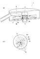
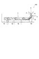
図1は、本発明の実施形態に係るシャワー装置1を例示する模式図である。図1(a)は模式斜視断面図であり、図1(b)は図1(a)の模式斜視断面図の底面側から見たときの模式平面図(模式底面図)である。
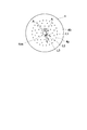
図2は、散水孔4pの配置を例示する模式平面図である。
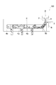
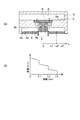
図3は、シャワー装置1の構成を例示する模式断面図である。
Hereinafter, embodiments of the present invention will be described with reference to the drawings. In addition, in each drawing, the same code | symbol is attached | subjected to the same component and detailed description is abbreviate | omitted suitably.
FIG. 1 is a schematic view illustrating a
FIG. 2 is a schematic plan view illustrating the arrangement of the watering
FIG. 3 is a schematic cross-sectional view illustrating the configuration of the
シャワー装置1は、水を通す給水路Sと、給水路S(図1では、給水路Sの下流側の端部)に設けられ、水に空気を混入する空気混入部3と、空気混入部3の下流側に設けられ、空気を含んだ水である空気含有水(気泡水)を吐出する複数の散水孔4pを有する散水部4と、を備える。
The
また、図1の例では、シャワー装置1は、絞り部2を備えている。絞り部2は、空気混入部3の上流側に設けられ、給水路Sを通る水の流路断面積を減らして水を吐出する。これにより、絞り部2は、気泡水の進行方向を規制することができる。
In the example of FIG. 1, the
空気混入部3は、開口3aを有する。給水路Sに供給された水は、絞り部2を通過し、その水の運動エネルギーにより、開口3aから空気を引き込む。なお、図1(b)において、水流方向は空気混入部3から放射状に進む方向であり、矢印Aは水流方向の一部のみを表している。
The
散水部4は、複数の散水孔4pを有する散水板4bを有する。散水部4の形状は、図示した円形形状の他、矩形や他の任意の形状であってもよい。また、散水部4の内部空間の厚さW(図3参照)は、噴射口2aの径または幅に対して、上下(厚さWの方向)に1mm弱程度から数mm程度の差を有するように設定することができる。例えば、噴射口2aの径が1mm弱程度である場合、散水部4の内部空間の厚さWは、2〜3mm程度とすることができる。
The watering
本実施形態において、散水部4は、空気混入部3から散水孔4pが存在する位置までの距離を少なくとも3つ有する。これにより、散水する領域が適切に確保され、心地よい水の「当たり感」を得ることができる。ここで、本明細書において、「散水孔4pが存在する」とは、「散水孔4pの重心(円形の場合は、中心)が存在する」を意味するものとする。このため、「散水孔4pが存在する位置」とは、「散水孔4pの重心(中心)が存在する位置」を意味する。
In this embodiment, the
そして、シャワー装置1は、散水部4における気泡水の進行方向(以下、「水流方向」という)の直線上における、前述した距離から選択される少なくとも3つの異なる距離にある位置の組合せの少なくともいずれかの組合せの両端を結ぶ線分であって、散水孔4pが存在する線分において、散水孔4pは1つだけ存在する。ここで、「散水部4における気泡水の進行方向(水流方向)」とは、散水部4における気泡水の主な進行方向をいう。散水部4において気泡水は微視的には様々な方向に進むと考えられるところ、相対的な進行方向という意味である。また、「散水孔4pが存在する線分」とは、「散水孔4pの重心(中心)が存在する線分」を意味する。
And the
図1(b)に表したように、シャワー装置1においては、矢印Aで示した水流方向の直線上における、空気混入部3から3つの異なる距離にある位置の組合せの少なくともいずれか(例えば、距離L1(第1の距離)、L2(第2の距離)、及びL3(第3の距離)の位置。あるいは、距離L1、L2、及びL4の位置)の両端を結ぶ線分であって、散水孔4pが存在する線分(例えば、線分P1やP2)において、散水孔4pは1つだけ存在する。
換言すると、距離L1(第1の距離)にある散水孔4p(第1の散水孔)と、距離L2(第2の距離)にある散水孔4p(第2の散水孔)と、距離L3(第3の距離)にある散水孔4p(第3の散水孔)のそれぞれは、矢印Aで表した水流方向の直線上において、これら距離L1、L2、L3にある散水孔4p(第1、第2及び第3の散水孔)のうちの他のいずれとも重ならないように配置されている。
As shown in FIG. 1B, in the
In other words, the
なお、図2に表したように、水流方向において散水孔4pの一部が重複してもよい(斜線部)。図示した線分P1のように、散水孔4p(の重心(中心))が存在する線分において、散水孔4pが1つ(散水孔4pa)だけ存在する限り、本実施形態に含まれる。
In addition, as represented to FIG. 2, a part of sprinkling
散水孔4pをこのように配置することにより、後述するように散水部4内で渦の発生が抑制される。これにより、散水部4内での圧損が低減し、均一な微細気泡を含んだ水が散水部4内に均一に分散する。この結果、気泡水が散水部4から均一に流出することができる。
By arranging the sprinkling
シャワー装置1は、図3に表した構成を含め、多様な構成にすることができる。図3(a)及び(b)は、散水部4において水が中心部から放射状に流れる「ラジアル型」のシャワー装置であり、図3(c)は「非ラジアル型」のシャワー装置である。また、図3(a)に表したシャワー装置では、給水路Sから供給された水は散水孔4pが配された面(散水面4a)に対して略垂直に流れ込み、図3(b)及び(c)に表したシャワー装置では、給水路Sから供給された水は散水面4aに沿って流れ込む。
The
前述したように、シャワー装置1は、水流方向を規制する絞り部をさらに備えることができる。これにより、水流を所望の方向に進行させることができる。絞り部は、例えば、図3(a)〜(c)に示した絞り部2である。絞り部2は、給水路S(例えば、給水路Sの下流側の端部)に設けられ、開口(噴射口2a)などにより水の流路断面積を減らして、水の運動エネルギーを高めた状態で大気開放となった空間に水を吐出する。この場合、空気混入部3は、絞り部2の下流側に設けられ、矢印Bで示したように絞り部2から吐出された水の運動エネルギーにより、空気を引き込み、散水部4内に空気を混入させる。
As described above, the
給水路Sに導入され絞り部2から吐出された水は(矢印A)、図3(a)に表したように複数の散水孔4pが配された面(散水面4a)に対して垂直な方向に吐出される構成にすることができる。この場合、水はまず散水面4aに対して垂直の方向に進み、空気混入部3において空気を取り込む(矢印B)。その後、界面4sにあたった後、斜面50にあたってその流れ方向が散水面4aに沿った方向に変化する。
The water introduced into the water supply channel S and discharged from the throttle unit 2 (arrow A) is perpendicular to the surface (
また、給水路Sに導入され絞り部2から吐出された水は(矢印A)、図3(b)及び(c)に表したように散水面4aに沿って吐出される構成にすることができる。この場合、絞り部2から吐出された水は空気混入部3において空気を取り込み(矢印B)、そのまま同じ方向に散水部4内を進む。ここで、「散水面4aに沿って吐出される」とは、散水面4aの全部または一部の直上において散水面4aに沿って吐出されることの他、散水面4aの全部または一部と離隔した領域において散水面4aと略平行に吐出されることも含む。また、吐水の方向は散水面4aに対して厳密に平行である必要はなく、散水面4aに対して傾斜したものも、本具体例の範囲に包含される。
Further, the water introduced into the water supply channel S and discharged from the throttle portion 2 (arrow A) may be discharged along the
また、シャワー装置1は、図3(b)に表したように、給水路Sを流れる水をシャワーの吐水方向に対して略平行な方向で受ける給水受け部Tを有してもよい。この場合、絞り部2は給水受け部Tに設けることができる。給水路Sに導入された水は、給水受け部Tで受けられ、ここで進行方向を散水面4aに略平行な方向に変えて噴射口2aから吐出される。その後、前述したように空気を取り込んで、噴射口2aから吐出された方向と同じ方向に散水部4内を進む。
Moreover, the
給水路Sに水を供給し散水部4からシャワー流を吐水させている状態において、空気混入部3と散水部4との境界付近には、気液が混ざる界面4sが形成される。界面4sを境に、空気混入部3側は絞り部2からの水が大気中に開放された状態となっており、散水部4側は絞り部2からの水とそれによって引き込まれる空気とが混ざり、気泡水200が存在する状態となっている。すなわち、絞り部2からの水と、その水の運動エネルギーによって引き込まれる空気と、が界面4sに衝突することで、気液が混ざり気泡水200が形成されることになる。
In the state where water is supplied to the water supply channel S and the shower flow is discharged from the
次に、本実施形態の効果について、図4及び図5を参照しつつ説明する。
まず、本実施形態では、散水部4は、散水孔4pが配される列を3つ以上有する。すなわち、空気混入部3から散水孔4pが存在する位置までの距離を少なくとも3つ有する。これにより、散水孔4pが配される列を2つ以下だけ有する散水部4を備えたシャワー装置に比べて、散水する領域が十分確保される。このため、心地よい水の「当たり感」を得ることができる。
Next, the effect of this embodiment will be described with reference to FIGS.
First, in this embodiment, the watering
次に、散水孔4pを本実施形態のように配置することの効果について説明する。
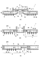
図4は、本実施形態と対比される比較例に係るシャワー装置100における散水孔4pの配置を表した模式平面図である。図4(a)及び(c)は散水孔4pの配置を例示する模式平面図であり、図4(b)及び(d)はそれぞれ図4(a)及び(c)に表した散水板4bを用いた場合の水の流路を表した模式平面図である。
図5は、比較例に係るシャワー装置100の散水部4内の状況を表した模式断面図である。
Next, the effect of arranging the sprinkling
FIG. 4 is a schematic plan view showing the arrangement of the
FIG. 5 is a schematic cross-sectional view showing a situation inside the watering
図4(a)及び(c)に表したように、比較例に係る散水部4は、本実施形態と同様に空気混入部3から散水孔4pが存在する位置までの距離を少なくとも3つ有する。しかし、水流方向の直線上における、この距離から選択される少なくとも3つの異なる距離にある位置の組合せの少なくともいずれかの組合せの両端を結ぶ線分であって、散水孔4pが存在する線分において、散水孔4pは複数存在することがある。例えば、図4(a)に表した例では、破線Rで示した方向にある、距離L1からL3までの線分Pでは、散水孔4pは2つまたは3つ存在する。また、図4(c)に表した例では、破線Rで示した方向にある、距離L1からL3までの線分Pでは、散水孔4pは1つまたは2つ存在する。
As shown in FIGS. 4A and 4C, the
この場合、図4(b)及び(d)に示したように、散水孔4pが2つ以上存在する線分上において、空気混入部3に遠い側(下流側)にある散水孔4p(以下、「下流側散水孔4pd」という)には、水は回り込むようにして入水する。下流側散水孔4pdと空気混入部3との間には、空気混入部3に近い側(上流側)の散水孔4p(以下、「上流側散水孔4pu」という)が存在するため、空気混入部3から下流側散水孔4pdに真っ直ぐに入水することができないからである。この結果、隣接する回り込んだ水流の間などで渦や乱れが発生する可能性が高くなる。
In this case, as shown in FIGS. 4B and 4D, on the line segment where two or
これにより、気泡水の運動エネルギーは減少し、散水部4において気泡水の流速が適切に確保されないことがある。この結果、図5に表したように、散水部4において下流側に向かうにつれ、気泡同士が結合して成長し、停滞する。これにより、気泡溜まりができ、気泡径が散水孔4pの径よりも大きい場合などに気泡水が散水孔4pから効率よく流出しないことがある。すなわち、散水部4の下流側においては、気泡を十分に含まない水が吐出され、吐出後において連続した水流がせん断等によって粒化されやすい。このため、大粒化した粒状の吐水を形成することが難しい。さらに、空気を混入することにより、水の流量に空気の流量が加わるため、吐水後の粒の流速は高くなると考えられるが、散水部4の下流側においては気泡を十分に含まない水が吐出されるため、流速が高くならない。従って、比較例では、シャワーが体表面に当たったときの刺激感や質感に乏しく、十分な「当たり感」が得られにくい。これを得るためには、水量を大きくし、流速を高めて、運動エネルギーを増加しなくてはならない。
Thereby, the kinetic energy of bubble water decreases and the flow rate of bubble water may not be ensured appropriately in the
一方、図6は、本実施形態に係るシャワー装置1における散水孔4pの配置を例示する模式平面図である。図6(a)及び(c)は散水孔4pの配置を例示する模式平面図であり、図6(b)及び(d)はそれぞれ図6(a)及び(c)に表した散水板4bを用いた場合の水の流路を表した模式平面図である。なお、図6(a)は図1(b)と同じ図であり、矢印Aは水流方向の一部のみを表している。実際には水は空気混入部3から放射状に進む。
図7は、本実施形態に係るシャワー装置1の散水部4内の状況を表した模式断面図である。
On the other hand, FIG. 6 is a schematic plan view illustrating the arrangement of the
FIG. 7 is a schematic cross-sectional view showing a situation in the watering
図6(a)及び(c)に表したように、本実施形態に係る散水部4では、矢印A等の水流方向の直線上であって散水孔4pが存在する直線上にある、例えば距離L1からL3までの線分(P1など)や、距離L1からL4までの線分(P2など)において、散水孔4pは1つだけ存在する。
この場合、図6(b)及び(d)に示したように、線分P1やP2において、上流側散水孔4puのみならず下流側散水孔4pdにも水は真っ直ぐに入水しやすい。下流側散水孔4pdと空気混入部3との間には上流側散水孔4puが比較例に比べて少なく、水の回り込みが発生する可能性が低いため、渦や乱れの発生が抑制される。
As shown in FIGS. 6A and 6C, in the
In this case, as shown in FIGS. 6B and 6D, in the line segments P1 and P2, water easily enters straightly not only into the upstream water spray hole 4pu but also into the downstream water spray hole 4pd. Compared to the comparative example, the number of upstream water spray holes 4pu between the downstream water spray hole 4pd and the
このように、第1、第2及び第3の散水孔4pのそれぞれを、水流方向の直線上において、第1、第2及び第3の散水孔4pのうちの他のいずれとも重ならないように配置することで、散水部4内の空気含有水(気泡水)の流れを分散させることができる。気泡水の流れを散水部4内で分散させることで、各散水孔4pへ向かう流れの停滞が無くなるため、気泡の停滞・結合が起こらない。このため、気泡水が各散水孔4pから吐出され易い。さらに、流れの停滞による散水部4での渦発生を抑制できるため、散水部4での圧力損失が低減できる。
Thus, each of the first, second, and
このように、効率的に気泡水を散水孔4pから吐出することができるため、シャワーの粒径及び流速を同時に大きくすることができ、良好な質感のシャワーが得られるシャワー装置が提供される。
As described above, since the bubbly water can be efficiently discharged from the sprinkling
また、本実施形態によれば、散水孔4pを複数列(図1及び図6では3列)設け、第1、第2及び第3の散水孔4pのそれぞれを、水流方向の直線上において、第1、第2及び第3の散水孔4pのうちの他のいずれとも重ならないように配置している。これらにより、広範囲でありながら気泡の停滞等が生じない効率的な吐水を行うことができる。
Moreover, according to this embodiment, the
なお、距離L1は、空気混入部3から複数の散水孔4pまでの距離のうちのn(「n」は、1以上の整数)番目に小さい距離とし、距離L2は、空気混入部3から複数の散水孔4pまでの距離のうちの(n+1)番目に小さい距離とし、距離L3は、空気混入部3から複数の散水孔4pまでの距離のうちの(n+2)番目に小さい距離とすることができる。とりわけ、距離L1、L2、L3は、空気混入部3から複数の散水孔4pまでの距離のうちの、それぞれ1番目、2番目、3番目に小さい距離とすることができる。換言すると、線分P1やP2は、空気混入部3から最も近い(すなわち、最上流側の)3つの異なる距離にある位置を含むことができる。これにより、回り込みが上流側で発生することを抑制することができ、散水部4内での渦や乱れの発生をさらに抑制することができる。
The distance L1 is the nth smallest distance (“n” is an integer equal to or greater than 1) of the distances from the
第1、第2及び第3の散水孔4pのそれぞれを、水流方向の直線上において、第1、第2及び第3の散水孔4pのうちの他のいずれとも重ならないように配置し、散水孔4pまでの距離を少なくとも3つとすることで、上記と同様の効果を得ることができる。さらに、散水孔4pを散水部4に満遍なく配置し、散水部4をよりコンパクトにした状態でも同様の効果を得ることができる。また、この様に散水孔4pを散水部4に満遍なく配置する構成にすることで、散水孔4pから吐出された水は、広範囲に密な吐水とすることができ、快適な浴び心地が得られる。
Each of the first, second and
このように渦や乱れの発生が抑制されることにより、図7に示したように、比較例に比べて散水部4内での運動エネルギーの減少が抑制され、圧損が低減する。このため、気泡水の流速が適切に確保される。この結果、散水部4の上流側から下流側に至るまで、サイズが均一な微細気泡が均一に分散することができる。これにより、気泡溜まりなどが生じにくく、水は均一な微細気泡を含んだまま散水部4から均一に吐出される。つまり、本実施形態によれば、散水部4の上流側でも下流側でも、気泡を含有した水を吐出させ、粒状の大粒化した吐水を形成することができる。これにより、吐出される水は各散水孔4pで大粒化され易くなり、また流速も高くなることから粒の運動エネルギーが増加し、これらにより十分な「当たり感」が得られる。
By suppressing the occurrence of vortices and turbulence in this way, as shown in FIG. 7, a decrease in kinetic energy in the sprinkling
従って、本実施形態では、シャワーが体表面に当たったときに良好な刺激や質感が得られる。すなわち、少ない水量でも十分な「当たり感」が得られる。本実施形態は、浴室やキッチン等で用いられるハンディ型または固定型のシャワーなどに好適に適用することができる。 Therefore, in this embodiment, when the shower hits the body surface, good stimulation and texture can be obtained. That is, a sufficient “feel” can be obtained even with a small amount of water. The present embodiment can be suitably applied to a handy type or a fixed type shower used in a bathroom or kitchen.
水流方向は、図6(a)に表したように、空気混入部3などから放射状に進む方向とすることができる。また、空気混入部3が設けられた給水路Sの給水口は、散水部4の略中心に設けることができる。これらのように構成することにより、気泡水を散水部4内にさらに均一に流すことができる。すなわち、散水部4の中心部から周辺部に至るまで、気泡水は側面などに衝突することなく略同一の流速で放射状の各方向に進むことができる。
As shown in FIG. 6A, the water flow direction can be a direction that proceeds radially from the
なお、比較例において、絞り部2の噴射口2aの開口面積を小さくすることにより散水部4内の水(気泡水)の流速を向上させることも考えられるが、この場合でも、前述した回り込み水流により運動エネルギーが減殺される。これに対し、本実施形態では、より効果的に散水部4内の水(気泡水)の流速を確保することができる。
In the comparative example, it is conceivable to improve the flow rate of water (bubble water) in the sprinkling
このように、本実施形態によれば、均一な気泡を有する水を散水面から均一に吐出することができるシャワー装置が提供される。 Thus, according to this embodiment, the shower apparatus which can discharge uniformly the water which has a uniform bubble from a water spray surface is provided.
次に、本実施形態の他の構成について、図8を参照しつつ説明する。
図8は、シャワー装置1の他の構成を例示する模式平面図である。図8(a)はシャワー装置1の他の構成を例示する模式平面図であり、図8(b)は水の流路を表した模式平面図である。
Next, another configuration of the present embodiment will be described with reference to FIG.
FIG. 8 is a schematic plan view illustrating another configuration of the
図8(a)に表したように、本実施形態では、散水部4の外周に空気混入部3が設けられた構成にしてもよい。この場合も、図8(b)に表したように、上流側散水孔4puのみならず下流側散水孔4pdにも水は真っ直ぐに入水しやすい。この結果、渦や乱れの発生が抑制され、前述した機構により均一な微細気泡を含んだ気泡水が散水部4から均一に吐出される。このため、シャワーが体表面に当たったときに良好な刺激や質感が得られる。
As shown in FIG. 8A, in the present embodiment, the
次に、本実施形態のさらに別の構成について、図9を参照しつつ説明する。
図9は、散水部4の他の構成を例示する模式平面図である。
図9に表したように、散水板4bの上流側に、散水孔4pよりも径の小さい小孔4psを設けてもよい。この場合、矢印Aで示した水流方向の直線上において、小孔4psは散水孔4pと重なってもよい。小孔4psの径が小さいため、小孔4psから吐出される気泡水の量は少ないことから、散水部4内で気泡水の流速は低下しにくいと考えられる。また、小孔4psから気泡水が流出しにくいため、渦もできにくいと考えられる。このため、前述した機構により均一な微細気泡を含んだ気泡水が散水部4から均一に吐出され、シャワーが体表面に当たったときに良好な刺激や質感が得られる。
Next, still another configuration of the present embodiment will be described with reference to FIG.
FIG. 9 is a schematic plan view illustrating another configuration of the
As shown in FIG. 9, a small hole 4ps having a diameter smaller than that of the
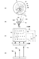
次に、本実施形態のさらに別の構成について、図10及び図11を参照しつつ説明する。
図10(a)は、散水部4の内部空間の厚さWが一定であるラジアル型シャワー装置を例示する模式断面図であり、図10(b)は、図10(a)に表したシャワー装置を用いた場合の、散水部4内の流速を例示した模式グラフ図である。横軸は空気混入部3の中心からの距離を表し、縦軸は散水部4内の水の流速を表している。
また、図11は、散水部4を例示する模式断面図である。
Next, still another configuration of the present embodiment will be described with reference to FIGS. 10 and 11.
FIG. 10A is a schematic cross-sectional view illustrating a radial shower device in which the thickness W of the internal space of the
FIG. 11 is a schematic cross-sectional view illustrating the
図10(b)に表したように、散水部4内で下流側に向かうにつれて水の流速が低下することがある。特に、散水孔4p近傍において急速に低下することがある(距離L1、L2、L3等)。
これは、散水部4が放射状に広がるため、中心からの距離が増加するにつれて、散水部4内の断面積が増加し、流速が低くなっていくためである。さらに、散水部4内の水は、中心から下流側に向けて進むにつれて散水孔4pから徐々に吐出されていくため、中心からの距離が増加するにつれて、散水部4内の水の流速は低下する。後者の事象は、非ラジアル型のシャワー装置にも当てはまる。
As illustrated in FIG. 10B, the flow rate of water may decrease toward the downstream side in the
This is because the sprinkling
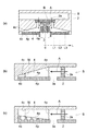
このため、図11に表したように、散水部4の内部空間の厚さWは、空気混入部3から遠ざかるにつれて小さくなる構成にすることができ、これにより散水部4内での流速の低下を抑制することができる。図11(a)は、給水路Sから供給された水が散水面4aに対して略垂直に流れ込む構成のシャワー装置の散水部4を例示し、図11(b)及び(c)は、給水路Sから供給された水が散水面4aに沿って流れ込む構成のシャワー装置の散水部4を例示している。図11(a)〜(c)に表した、散水部4が先細りになる構成は、ラジアル型のみならず非ラジアル型にも適用することができる。
For this reason, as shown in FIG. 11, the thickness W of the internal space of the
散水部4は、図11(a)及び(b)に表したように、下流側に向かうにつれて対向面4c(散水面4aに対向する面)が散水面4a側に傾斜する構成にすることができる。また、図11(c)に表したように、下流側に向かうにつれて散水面4aが対向面4c側に傾斜する構成にすることができる。これにより、散水部4内での圧損が低減し、水の流速を適切に確保できるため、散水部4内での気泡の停滞・結合や渦の発生が抑制され、微細気泡が吐出し易くなる。さらに、散水孔4pから吐出された水は大粒化し、流速も上がるため、シャワーが体表面に当たったときに良好な刺激や質感が得られる。
As shown to Fig.11 (a) and (b), the sprinkling
なお、散水孔4pは、図11(c)に表したように、散水部4の内部側と外部側とで流路断面積を変えることができ、例えば外部側が相対的に小さい流路断面積を有する構成にすることができる。これにより、散水孔4pから吐出される気泡水の流速を適切に確保することができる。
In addition, as shown in FIG.11 (c), the sprinkling
以上、具体例を参照しつつ本発明の実施の形態について説明した。しかし、本発明はこれらの具体例に限定されるものではない。すなわち、これら具体例に、当業者が適宜設計変更を加えたものも、本発明の特徴を備えている限り、本発明の範囲に包含される。例えば、前述した各具体例が備える各要素およびその配置、材料、条件、形状、サイズなどは、例示したものに限定されるわけではなく適宜変更することができる。
また、前述した各実施の形態が備える各要素は、技術的に可能な限りにおいて組み合わせることができ、これらを組み合わせたものも本発明の特徴を含む限り本発明の範囲に包含される。
The embodiments of the present invention have been described above with reference to specific examples. However, the present invention is not limited to these specific examples. In other words, those specific examples that have been appropriately modified by those skilled in the art are also included in the scope of the present invention as long as they have the characteristics of the present invention. For example, the elements included in each of the specific examples described above and their arrangement, materials, conditions, shapes, sizes, and the like are not limited to those illustrated, but can be changed as appropriate.
Moreover, each element with which each embodiment mentioned above is provided can be combined as long as technically possible, and the combination of these is also included in the scope of the present invention as long as it includes the features of the present invention.
1 シャワー装置、2 絞り部、2a 開口、噴射口、3 空気混入部、3a 開口、4 散水部、4a 散水面、4b 散水板、4c 対向面、4p 散水孔、4pd 下流側散水孔、4ps 小孔、4pu 上流側散水孔、4s 界面、50 斜面、100 シャワー装置、200 水、気泡水、A 矢印(水の流路)、B 矢印(空気の流路)、L1、L2、L3、L4 距離、P、P1、P2 線分、S 給水路、T 給水受け部、W 厚さ 1 shower device, 2 constricting part, 2a opening, jetting port, 3 aeration unit, 3a opening, 4 watering part, 4a watering surface, 4b watering plate, 4c facing surface, 4p watering hole, 4pd downstream watering hole, 4ps small Hole, 4pu upstream water spray hole, 4s interface, 50 slope, 100 shower device, 200 water, bubble water, A arrow (water flow path), B arrow (air flow path), L1, L2, L3, L4 distance , P, P1, P2 line segment, S water supply channel, T water supply receiving part, W thickness
Claims (4)
前記給水路に設けられ、前記水に空気を混入する空気混入部と、
前記空気混入部の下流側に設けられ、前記空気を含んだ水である空気含有水を吐出する複数の散水孔を有する散水部と、
を備え、
前記散水部は、前記空気混入部から第1の距離にある第1の散水孔と、前記空気混入部から前記第1の距離よりも大なる第2の距離にある第2の散水孔と、前記空気混入部から前記第1及び第2の距離よりも大なる第3の距離にある第3の散水孔と、を有し、
前記第1、第2及び第3の散水孔のそれぞれは、前記散水部における前記空気含有水の進行方向である水流方向の直線上において、前記第1、第2及び第3の散水孔のうちの他のいずれとも重ならないように配置されていることを特徴とするシャワー装置。 A water supply channel for passing water,
An aeration unit that is provided in the water supply channel and mixes air into the water;
A watering part that is provided on the downstream side of the air mixing part and has a plurality of watering holes for discharging air-containing water that is water containing the air,
With
The water sprinkling part has a first water sprinkling hole at a first distance from the air mixing part, and a second watering hole at a second distance larger than the first distance from the air mixing part, A third sprinkling hole at a third distance larger than the first and second distances from the aeration unit,
Each of the first, second, and third sprinkling holes is a straight line in the water flow direction that is the traveling direction of the air-containing water in the sprinkling part, and is among the first, second, and third sprinkling holes. A shower device characterized by being arranged so as not to overlap with any other.
前記第2の距離は、前記空気混入部から前記複数の散水孔までの距離のうちの2番目に小さい距離であり、
前記第3の距離は、前記空気混入部から前記複数の散水孔までの距離のうちの3番目に小さい距離であることを特徴とする請求項1記載のシャワー装置。 The first distance is the smallest distance among the distances from the aeration unit to the plurality of water spray holes,
The second distance is a second smallest distance among the distances from the aeration unit to the plurality of water spray holes,
The shower apparatus according to claim 1, wherein the third distance is a third smallest distance among the distances from the aeration unit to the plurality of water spray holes.
Priority Applications (1)
| Application Number | Priority Date | Filing Date | Title |
|---|---|---|---|
| JP2008320570A JP2010142336A (en) | 2008-12-17 | 2008-12-17 | Shower device |
Applications Claiming Priority (1)
| Application Number | Priority Date | Filing Date | Title |
|---|---|---|---|
| JP2008320570A JP2010142336A (en) | 2008-12-17 | 2008-12-17 | Shower device |
Publications (1)
| Publication Number | Publication Date |
|---|---|
| JP2010142336A true JP2010142336A (en) | 2010-07-01 |
Family
ID=42563396
Family Applications (1)
| Application Number | Title | Priority Date | Filing Date |
|---|---|---|---|
| JP2008320570A Pending JP2010142336A (en) | 2008-12-17 | 2008-12-17 | Shower device |
Country Status (1)
| Country | Link |
|---|---|
| JP (1) | JP2010142336A (en) |
Cited By (3)
| Publication number | Priority date | Publication date | Assignee | Title |
|---|---|---|---|---|
| JP2013121414A (en) * | 2011-12-09 | 2013-06-20 | Fujidenoro Co Ltd | Carbonated spring generating device |
| WO2014167783A1 (en) * | 2013-04-11 | 2014-10-16 | パナソニック株式会社 | Shower head |
| JP2020010962A (en) * | 2018-07-20 | 2020-01-23 | 株式会社サイエンス | Shower head and bubble generation unit |
-
2008
- 2008-12-17 JP JP2008320570A patent/JP2010142336A/en active Pending
Cited By (5)
| Publication number | Priority date | Publication date | Assignee | Title |
|---|---|---|---|---|
| JP2013121414A (en) * | 2011-12-09 | 2013-06-20 | Fujidenoro Co Ltd | Carbonated spring generating device |
| WO2014167783A1 (en) * | 2013-04-11 | 2014-10-16 | パナソニック株式会社 | Shower head |
| JP2014204796A (en) * | 2013-04-11 | 2014-10-30 | パナソニック株式会社 | Shower head |
| JP2020010962A (en) * | 2018-07-20 | 2020-01-23 | 株式会社サイエンス | Shower head and bubble generation unit |
| WO2020017066A1 (en) * | 2018-07-20 | 2020-01-23 | 株式会社サイエンス | Shower head |
Similar Documents
| Publication | Publication Date | Title |
|---|---|---|
| EP2881178B1 (en) | Shower apparatus | |
| JP5505700B2 (en) | Shower equipment | |
| JP5489067B2 (en) | Shower equipment | |
| JP4623329B2 (en) | Shower equipment | |
| US11248368B2 (en) | Faucet aerator with center stream | |
| JP2010188046A (en) | Shower device | |
| JP5854365B2 (en) | Foam spouting device | |
| JP3837744B1 (en) | shower head | |
| JP2010142336A (en) | Shower device | |
| JP5477772B2 (en) | Shower equipment | |
| JP2016087221A (en) | Shower device | |
| JP2014180387A (en) | Shower apparatus | |
| JP2010227181A (en) | Shower head | |
| JP5633784B2 (en) | Shower equipment | |
| JP6048656B2 (en) | shower head | |
| JP6315247B2 (en) | Water discharge device | |
| JP5704463B2 (en) | Shower equipment | |
| US20110174894A1 (en) | Showerhead with multiple aerating orifice plates | |
| JP2016097341A (en) | Water discharge device | |
| JP2012005567A (en) | Shower device | |
| JP2015194040A (en) | water discharge device |