EP2412836B1 - Maraging steel strip - Google Patents
Maraging steel strip Download PDFInfo
- Publication number
- EP2412836B1 EP2412836B1 EP10756175.5A EP10756175A EP2412836B1 EP 2412836 B1 EP2412836 B1 EP 2412836B1 EP 10756175 A EP10756175 A EP 10756175A EP 2412836 B1 EP2412836 B1 EP 2412836B1
- Authority
- EP
- European Patent Office
- Prior art keywords
- less
- treatment
- content
- steel
- maraging steel
- Prior art date
- Legal status (The legal status is an assumption and is not a legal conclusion. Google has not performed a legal analysis and makes no representation as to the accuracy of the status listed.)
- Active
Links
Images


Classifications
-
- C—CHEMISTRY; METALLURGY
- C23—COATING METALLIC MATERIAL; COATING MATERIAL WITH METALLIC MATERIAL; CHEMICAL SURFACE TREATMENT; DIFFUSION TREATMENT OF METALLIC MATERIAL; COATING BY VACUUM EVAPORATION, BY SPUTTERING, BY ION IMPLANTATION OR BY CHEMICAL VAPOUR DEPOSITION, IN GENERAL; INHIBITING CORROSION OF METALLIC MATERIAL OR INCRUSTATION IN GENERAL
- C23C—COATING METALLIC MATERIAL; COATING MATERIAL WITH METALLIC MATERIAL; SURFACE TREATMENT OF METALLIC MATERIAL BY DIFFUSION INTO THE SURFACE, BY CHEMICAL CONVERSION OR SUBSTITUTION; COATING BY VACUUM EVAPORATION, BY SPUTTERING, BY ION IMPLANTATION OR BY CHEMICAL VAPOUR DEPOSITION, IN GENERAL
- C23C8/00—Solid state diffusion of only non-metal elements into metallic material surfaces; Chemical surface treatment of metallic material by reaction of the surface with a reactive gas, leaving reaction products of surface material in the coating, e.g. conversion coatings, passivation of metals
- C23C8/06—Solid state diffusion of only non-metal elements into metallic material surfaces; Chemical surface treatment of metallic material by reaction of the surface with a reactive gas, leaving reaction products of surface material in the coating, e.g. conversion coatings, passivation of metals using gases
- C23C8/08—Solid state diffusion of only non-metal elements into metallic material surfaces; Chemical surface treatment of metallic material by reaction of the surface with a reactive gas, leaving reaction products of surface material in the coating, e.g. conversion coatings, passivation of metals using gases only one element being applied
- C23C8/24—Nitriding
- C23C8/26—Nitriding of ferrous surfaces
-
- C—CHEMISTRY; METALLURGY
- C21—METALLURGY OF IRON
- C21D—MODIFYING THE PHYSICAL STRUCTURE OF FERROUS METALS; GENERAL DEVICES FOR HEAT TREATMENT OF FERROUS OR NON-FERROUS METALS OR ALLOYS; MAKING METAL MALLEABLE, e.g. BY DECARBURISATION OR TEMPERING
- C21D6/00—Heat treatment of ferrous alloys
- C21D6/02—Hardening by precipitation
-
- C—CHEMISTRY; METALLURGY
- C21—METALLURGY OF IRON
- C21D—MODIFYING THE PHYSICAL STRUCTURE OF FERROUS METALS; GENERAL DEVICES FOR HEAT TREATMENT OF FERROUS OR NON-FERROUS METALS OR ALLOYS; MAKING METAL MALLEABLE, e.g. BY DECARBURISATION OR TEMPERING
- C21D9/00—Heat treatment, e.g. annealing, hardening, quenching or tempering, adapted for particular articles; Furnaces therefor
- C21D9/46—Heat treatment, e.g. annealing, hardening, quenching or tempering, adapted for particular articles; Furnaces therefor for sheet metals
-
- C—CHEMISTRY; METALLURGY
- C22—METALLURGY; FERROUS OR NON-FERROUS ALLOYS; TREATMENT OF ALLOYS OR NON-FERROUS METALS
- C22C—ALLOYS
- C22C38/00—Ferrous alloys, e.g. steel alloys
- C22C38/001—Ferrous alloys, e.g. steel alloys containing N
-
- C—CHEMISTRY; METALLURGY
- C22—METALLURGY; FERROUS OR NON-FERROUS ALLOYS; TREATMENT OF ALLOYS OR NON-FERROUS METALS
- C22C—ALLOYS
- C22C38/00—Ferrous alloys, e.g. steel alloys
- C22C38/002—Ferrous alloys, e.g. steel alloys containing In, Mg, or other elements not provided for in one single group C22C38/001 - C22C38/60
-
- C—CHEMISTRY; METALLURGY
- C22—METALLURGY; FERROUS OR NON-FERROUS ALLOYS; TREATMENT OF ALLOYS OR NON-FERROUS METALS
- C22C—ALLOYS
- C22C38/00—Ferrous alloys, e.g. steel alloys
- C22C38/004—Very low carbon steels, i.e. having a carbon content of less than 0,01%
-
- C—CHEMISTRY; METALLURGY
- C22—METALLURGY; FERROUS OR NON-FERROUS ALLOYS; TREATMENT OF ALLOYS OR NON-FERROUS METALS
- C22C—ALLOYS
- C22C38/00—Ferrous alloys, e.g. steel alloys
- C22C38/06—Ferrous alloys, e.g. steel alloys containing aluminium
-
- C—CHEMISTRY; METALLURGY
- C22—METALLURGY; FERROUS OR NON-FERROUS ALLOYS; TREATMENT OF ALLOYS OR NON-FERROUS METALS
- C22C—ALLOYS
- C22C38/00—Ferrous alloys, e.g. steel alloys
- C22C38/18—Ferrous alloys, e.g. steel alloys containing chromium
- C22C38/40—Ferrous alloys, e.g. steel alloys containing chromium with nickel
- C22C38/44—Ferrous alloys, e.g. steel alloys containing chromium with nickel with molybdenum or tungsten
-
- C—CHEMISTRY; METALLURGY
- C22—METALLURGY; FERROUS OR NON-FERROUS ALLOYS; TREATMENT OF ALLOYS OR NON-FERROUS METALS
- C22C—ALLOYS
- C22C38/00—Ferrous alloys, e.g. steel alloys
- C22C38/18—Ferrous alloys, e.g. steel alloys containing chromium
- C22C38/40—Ferrous alloys, e.g. steel alloys containing chromium with nickel
- C22C38/50—Ferrous alloys, e.g. steel alloys containing chromium with nickel with titanium or zirconium
-
- C—CHEMISTRY; METALLURGY
- C22—METALLURGY; FERROUS OR NON-FERROUS ALLOYS; TREATMENT OF ALLOYS OR NON-FERROUS METALS
- C22C—ALLOYS
- C22C38/00—Ferrous alloys, e.g. steel alloys
- C22C38/18—Ferrous alloys, e.g. steel alloys containing chromium
- C22C38/40—Ferrous alloys, e.g. steel alloys containing chromium with nickel
- C22C38/52—Ferrous alloys, e.g. steel alloys containing chromium with nickel with cobalt
-
- C—CHEMISTRY; METALLURGY
- C22—METALLURGY; FERROUS OR NON-FERROUS ALLOYS; TREATMENT OF ALLOYS OR NON-FERROUS METALS
- C22C—ALLOYS
- C22C38/00—Ferrous alloys, e.g. steel alloys
- C22C38/18—Ferrous alloys, e.g. steel alloys containing chromium
- C22C38/40—Ferrous alloys, e.g. steel alloys containing chromium with nickel
- C22C38/54—Ferrous alloys, e.g. steel alloys containing chromium with nickel with boron
-
- C—CHEMISTRY; METALLURGY
- C21—METALLURGY OF IRON
- C21D—MODIFYING THE PHYSICAL STRUCTURE OF FERROUS METALS; GENERAL DEVICES FOR HEAT TREATMENT OF FERROUS OR NON-FERROUS METALS OR ALLOYS; MAKING METAL MALLEABLE, e.g. BY DECARBURISATION OR TEMPERING
- C21D2211/00—Microstructure comprising significant phases
- C21D2211/004—Dispersions; Precipitations
Definitions
- the invention relates to a maraging steel strip having improved fatigue strength. Particularly, the invention relates to a structural control of a nitrided structure obtained through nitriding treatment of a maraging steel strip for a metallic belt used in continuously variable transmissions for automobiles or the like.
- a maraging steel generally has a very high tensile strength of about 2000 MPa, and thus it has been used for members required to have high strength in various applications, such as rocket parts, centrifugal separator parts, aircraft parts, continuously variable transmission parts of automobile engines, or dies.
- a typical composition of the maraging steel contains 18% Ni, 8% Co, 5% Mo, 0.4% Ti, 0.1 % Al and the balance of Fe.
- the maraging steel contains appropriate amounts of Co, Mo and Ti as hardening elements, and can obtain high strength by precipitating intermetallic compounds such as Ni 3 Mo, Ni 3 Ti or Fe 2 Mo through aging treatment.
- intermetallic compounds such as Ni 3 Mo, Ni 3 Ti or Fe 2 Mo
- it is an important requirement to have fatigue strength particularly in a high cycle region for a steel strip used for continuously variable transmission parts of automobile engines.
- nonmetallic inclusions such as TiN, which are included in the maraging steel having the high strength, fine as far as possible.
- the maraging steel has been used by subjecting it to nitriding treatment to form a nitrided layer on its surface to improve fatigue strength.
- JP-A-2004-514056 Patent Literature 1
- JP-A-2001-240943 Patent Literature 2
- JP-A-2002-167652 Patent Literature 3
- the applicant also has proposed improved alloys for avoiding the decrease in fatigue strength occurring due to a nonmetallic inclusion as a starting point, which alloy contains reduced Ti content of 0. 1 mass% or less so as to substantially eliminate the inclusions such as TiN, in JP-A-2008-088540 (Patent Literature 4), JP-A-2007-186780 (Patent Literature 5) and WO2009-008071 (Patent Literature 6).
- Patent Literature 7 JP-A-2008-185183 has proposed a method for producing a maraging steel strip having high fatigue strength, in which the maraging steels described in the above Patent Literatures 4 to 6 are heated and maintained in a gas atmosphere containing fluorine compounds to remove an oxide film from their surface, and then are subjected to nitriding treatment at a temperature of 400 to 500°C in a nitriding gas that is controlled to have NH 3 /H 2 gas composition ratio from 1 to 3.
- Patent Literature 1 contains reduced Ti content of 0.1% or less since Ti forms nonmetallic inclusions. Therefore, although the alloy is advantageous in terms of including fine TiN acting as a starting point of fatigue fracture, the alloy has a problem of difficulty in nitriding treatment since it simply restrains addition of element which forms nonmetallic inclusions.
- Patent Literature 2 also contains a reduced Ti content, and therefore, it is advantageous in terms of making fine TiN acting as a starting point of fatigue fracture.
- the alloy has difficulty in ensuring high tensile strength since a Co content is kept low, that is one of hardening elements.
- Si and Mn are added to ensure the tensile strength. However, they likely decrease toughness.
- Patent Literature 3 also contains a reduced Ti content, and therefore, it is advantageous in terms of making fine TiN acting as a starting point of fatigue fracture.
- positive addition of C for increasing strength may lead to precipitation of carbides of Cr, Mo and the like which act as a starting point of fatigue fracture to decrease the fatigue strength, and the positively added C likely deteriorates weldability required for continuously variable transmission parts.
- the maraging steels proposed by the applicant in Patent Literatures 4 to 6 are alloys invented to solve problems of the maraging steels proposed in the above Patent Literatures 1 to 3.
- Patent Literature 7 fatigue strength can be further improved by specific nitriding treatment using the maraging steels proposed in Patent Literatures 4 to 6.
- Patent Literature 7 only temperatures and gas composition ratios for the nitriding treatment are discussed.
- Alloy elements in the maraging steels proposed in Patent Literatures 4 to 6 contain Cr and Al, which influence the fatigue strength since precipitation thereof changes during the nitriding treatment and influences on nitriding properties.
- the present inventors studied in detail a typical nitrided structure of precipitates generated during the nitriding treatment, and the influence thereof on the fatigue strength. As a result, the inventors found that the precipitates generated during the nitriding treatment greatly influence the fatigue strength.
- Other priort art examples for maraging steels can be found in JP 2009 013464 A and EP 1291445 A1 .
- An objective of the invention is to provide a maraging steel strip which has a composition capable of reducing TiN content acting as a starting point of fatigue fracture in a high cycle region, and having an improved bending fatigue strength by optimizing a nitrided structure after the nitriding treatment.
- a nitrided maraging steel strip comprising a nitrided layer on a surface of a maraging steel, consisting of by mass %, C: 0.01% or less, Si: 0.1% or less, Mn: 0.1% or less, P: 0.01% or less, S: 0.005% or less, Ni: 8.0 to 22.0%, Cr: 0.1 to 8.0%, Mo: 2.0 to 10.0%, Co: 2.0% to 20.0%, Ti: 0.1% or less, Al: 2.5% or less, N: 0.03% or less, O: 0.005% or less, optionally one or more of Ca: 0,01% or less, Mg:0,005% or less, and B:0.001% or less, optionally Zr:0.01% or less and the balance being Fe and unavoidable impurities, the nitrided layer comprising Cr nitride precipitated in the nitrided layer and a matrix martensite, characterized in that the Cr nitride and the martensite matrix satisfy the Baker
- one or more of, by mass %, Ca: 0.01% or less, Mg: 0.005% or less, and B: 0.01% or less may be contained.
- a maraging steel strip is more advantageous which contains Al less than 0.1%, and Al+Ti is restricted to 0.1% or less.
- TiN acting as a starting point of fatigue fracture can be reduced in the maraging steel, and excellent fatigue property can be obtained after nitriding treatment. Therefore, when the maraging is used for members required to have high fatigue strength, such as a power transmission metallic belt used for continuously variable transmissions for automobiles, it is expected to have an industrially remarkable advantage e.g. of being capable of obtaining long fatigue life.
- each chemical element is defined within following range, and the reason therefore is as follows. Please note that contents are described in mass % unless otherwise specified.
- Carbon (C) should be kept low since C forms carbides together with Mo to reduce precipitated intermetallic compounds and decrease strength of the steel. Moreover, positive addition of C increases a risk of deteriorating weldability required for e.g. continuously variable transmission parts. For these reasons, a C content is defined to be 0.01% or less. The C content is preferably 0.008% or less.
- Si makes intermetallic compounds fine during aging treatment and forms intermetallic compounds with Ni so that the element is capable of compensating for decrease in strength caused by reduction of Ti.
- Si content should be kept low to ensure toughness and ductility of the steel in the invention, since Si possibly decreases the toughness.
- Si content is defined to be 0.1% or less since addition of Si exceeding 0.1% decreases the toughness and ductility.
- the Si content is preferably 0.05% or less in order to surely ensure the toughness and ductility.
- Manganese (Mn) forms intermetallic compounds with Ni during aging treatment and contributes to age hardening, so that the element is capable of compensating for decrease in strength caused by reduction in Ti.
- Mn content should be kept low to ensure toughness and ductility of the steel in the invention since Mn possibly decreases the toughness.
- Mn content is defined to be 0.1% or less since addition ofMn exceeding 0.1% decreases the toughness and ductility.
- the Mn content is preferably 0.05% or less in order to surely ensure the toughness and ductility.
- Phosphor (P) and sulfur (S) segregate at old austenite grain boundaries and form inclusions. Thus, they are detrimental elements since they embrittle the maraging steel and decrease fatigue strength thereof. Therefore, P content is defined to be 0.01% or less, and S content is defined to be 0.005% or less. Preferably, the P content is in a range of 0.005% or less, and the S content is 0.004% or less.
- Chromium (Cr) decreases a nitriding depth, increases nitriding hardness, and increases compression residual stress of a nitrided surface since the element has strong affinity with nitrogen.
- addition of Cr is essential for the steel.
- the Cr content is defined to be 0.1 to 8.0%.
- the Cr content is preferable 0.2% or more and 4.0% or less.
- Ni nickel
- At least 8.0% of nickel (Ni) is required to stably form a low-C martensitic structure which is a matrix structure of the maraging steel.
- Ni content exceeding 22.0% stabilizes an austenitic structure, and makes it difficult to induce martensite transformation.
- the Ni content is defined to be from 8.0 to 22.0%.
- the preferable range of Ni is 17.0% or more and 22.0% or less.
- Molybdenum (Mo) is an important element for the steel since the element forms fine intermetallic compounds such as Ni 3 Mo and Fe 2 Mo during aging treatment and contributes to precipitation hardening. Moreover, Mo is effective for increasing surface hardness and compression residual stress due to nitriding. Mo content of less than 2.0% makes tensile strength of the steel insufficient, and Mo content exceeding 10.0% facilitates formation of coarse intermetallic compounds composed mainly of Fe and Mo. Thus, the Mo content is defined to be from 2.0 to 10.0%. The preferable range of Mo is 3.0% or more and 7.0% or less.
- Co Co
- Co is an important element since it promotes precipitation of fine intermetallic compounds containing Mo and Al, and contributes to aging precipitation hardening.
- Co increases degree of solid solution of aging precipitate-forming elements such as Mo and Al at a solid solution treatment temperature, and decreases degree of solid solution of Mo and Al at an aging precipitation temperature, without exerting a great influence on stability of a martensitic structure of the matrix of the steel.
- much Co content is necessary to be added from a viewpoint of strength and toughness, if the Co content is less than 2.0%, the maraging steel having reduced Si, Mn and Ti has difficulty in obtaining sufficient strength.
- the Co content is defined to be from 2.0% to 20.0%.
- Preferable range of Co is 4.0% or more and 20.0% or less.
- Co content is slightly increased since Al contributing to strengthening of the steel is decreased. Therefore, the Co content range is 10.0% or more and 20.0% or less.
- Titanium (Ti) is one of essential elements for hardening the maraging steel.
- Ti is a detrimental element at the same time since it forms inclusions such as TiN or Ti(C, N), thereby decreases fatigue strength of the steel particularly in an ultra-high cycle region. Therefore, in a case of placing importance on the fatigue strength, Ti is necessary to be kept low as an impurity level.
- Ti tends to form a thin and stable oxide film on a surface of the steel.
- the oxide film hinders nitriding reaction, and therefore makes it difficult to obtain a sufficient compression residual stress on a nitrided surface.
- Ti is a detrimental impurity element, and the content thereof is necessary to be kept low in order to facilitate nitriding and to increase the compression residual stress on the surface after nitriding.
- Ti content is defined to be 0.1% or less since Ti content of more than 0.1% does not produce sufficient effect of reducing TiN or Ti(C, N), and facilitates formation of the stable oxide film on the surface of the steel.
- the Ti content is preferably 0.05% or less, and further preferably 0.01% or less.
- Al may improve strength of the maraging steel. Therefore, when importance is placed on the strength, Al is preferably added.
- Al is usually added in a small amount for deoxidation, and essentially forms intermetallic compounds with Ni during aging treatment and contributes to strengthening. Since the maraging steel for a metallic belt of the invention has reduced Si, Mn and Ti, Al may compensate strength. Moreover, an effect may be also expected that a good nitrided layer is obtained by facilitating nitriding treatment in the maraging steel with reduced Ti.
- Al content of more than 2.5% is not preferable since much AlN and Al 2 O 3 inclusions are formed to decrease fatigue strength, or a thin and stable oxide film is formed on a surface of the steel to hinder nitriding reaction.
- Al is added positively, surface roughness of the maraging steel can be somewhat increased. Therefore, the upper limit of positively added Al is 1.5%.
- a total amount of Al and Ti is 0.1% or less.
- the preferable range of the Al+Ti content is 0.07% or less.
- Nitrogen (N) is an impurity element that is combined with Ti to form inclusions of TiN or Ti(C, N) and decreases fatigue strength particularly in ultra-high cycle region.
- the content ofN is necessary to be kept significantly low to prevent formation of coarse TiN or Ti(C, N).
- the N content is defined to be 0.03% or less since an amount ofN mixed in usual vacuum melting exerts a little adverse influence.
- the N content is 0.01% or less. Further desirably, the N content is 0.005% or less.
- Oxygen (O) is an impurity element that forms oxide-based inclusions and thereby decreases toughness and fatigue strength of the steel. Therefore, content of O is restricted to 0.005% or less. Desirably, the O content is 0.003% or less.
- one or more of Ca: 0.01% or less, Mg: 0.005% or less, and B: 0.01% or less may be contained.
- An ingot of the maraging steel of the invention may be produced by melting in a vacuum atmosphere, such as by vacuum induction melting or by vacuum induction melting followed by vacuum arc remelting or electroslag remelting.
- a vacuum atmosphere such as by vacuum induction melting or by vacuum induction melting followed by vacuum arc remelting or electroslag remelting.
- the steel of the invention may contain Al to improve strength of the steel, there are risks of formation of coarse and hard Al 2 O 3 inclusions exceeding e.g. 25 ⁇ m, or of occurrence of clustered Al 2 O 3 .
- the Al 2 O 3 inclusions have high hardness and high melting point, and are scarcely deformed, e.g., even during hot plastic working. Thereby, they may generate a flaw on a roll e.g. during cold rolling so that surface defect may be generated on the maraging steel for a metallic belt. Therefore, it is preferable that the Al 2 O 3 inclusions be made composite inclusions combined with other oxides to decrease hardness and lower melting point thereof.
- an element capable of preventing occurrence of the cluster is preferably added for preventing inclusion defects.
- Silicon (Si), manganese (Mn), calcium (Ca) and magnesium (Mg) are raised as the effective elements for making Al 2 O 3 composite inclusions.
- amounts of addition of Si and Mn are restricted since Si and Mn reduces toughness and ductility. Therefore, one or more of Ca and Mg other than Si and Mn may be added in the steel to make the Al 2 O 3 inclusions be composite inclusions.
- Ca and Mg also have an effect of preventing occurrence of cluster of Al 2 O 3 inclusions. Therefore, the steel of the invention contains Ca: 0.01% or less and/or Mg: 0.005% or less.
- the lower limit of content may be preferably 0.001% for Ca and 0.0001% for Mg.
- B Boron
- B is an element that makes old austenitic grains fine at the time of solid solution treatment after cold working and contributes to strengthening. B further has an effect of restraining roughness of a surface of the steel. Therefore, B may be optionally added.
- B content is defined to be 0.01% or less since the B content of more than 0.01% decreases toughness of the steel. The B content is desirably 0.005% or less.
- the preferable lower limit of the B content capable of surely making the old austenitic grains fine is 0.0002%.
- the balance other than the above described elements is iron (Fe) and unavoidable impurities.
- the steel may contain following element in following range for the purpose of deoxidation, desulfurization and the like.
- the maraging steel strip of the invention has an important advantage in that the maraging steel strip is adjusted to have an unconventional nitrided structure in which a substantial Baker-Nutting orientation relationship exists between Cr nitride and matrix martensite after nitriding treatment. Such a specific nitrided structure realizes further improvement of fatigue properties.
- the Baker-Nutting orientation relationship herein means that the nitrided structure and the matrix of the invention satisfy following relationships, 001 CrN / / 011 ⁇ , and 110 CrN / / 110 ⁇ . This will be explained in detail hereinafter.
- CrN chromium nitride
- the Cr nitride and the matrix martensite satisfy Baker-Nutting orientation relationship with an orientation difference within 10°, in order to specifically represent that substantial Baker-Nutting orientation relationship exists between the Cr nitride and the matrix martensite.
- orientation difference of the orientation relationship is larger than 10°, the precipitation hardening effect can not be expected.
- the maraging steel of the invention scarcely contains Ti since Ti forms on the surface of the steel a stable oxide film having a possibility of hindering nitriding. Therefore, it can be easily subjected to various types of nitriding treatment, such as usual gas nitriding, gas nitrocarburizing, nitrosulphurizing, ion nitriding, and salt bath nitriding.
- an appropriate solid solution treatment temperature is also important in addition to the composition of the maraging steel strip and the nitriding condition as described above.
- the solid solution treatment temperature is increased to 850 to 950°C to increase solid solubility of Cr in the alloy. This is because solid solubility of Cr tends to be insufficient when the solid solution treatment temperature is less than 850°C, and this makes it difficult to obtain the nitrided structure defined in the invention.
- the solid solution treatment temperature is more than 950°C, grain coarsening occurs. Therefore, the solid solution treatment temperature is defined to be from 850 to 950°C.
- Nitriding treatment temperature may range from 450 to 500°C, e.g., in the case of gas nitrocarburizing. Treating time is particularly important. The nitrided structure is sensitive to the treating time. The nitriding treatment temperature particularly changes since the various types of nitriding treatment may be applied as the nitriding treatment as described above. Therefore, it is preferred to check a nitrided structure by changing the treating time, after high temperature solid solution treatment, in order to obtain the nitrided structure of the invention in mass production.
- absolute value of compression residual stress of a nitrided layer may be increased by Cr and Al that have an effect of enhancing the nitriding hardness and the absolute value of compression residual stress of the nitrided layer, although the compression residual stress tends to decrease.
- the maraging steel strip for a metallic belt of the invention has a high tensile strength and fatigue strength, and is suitable for a metallic belt for a continuously variable transmission of automobile engines since it has excellent fatigue properties through the nitriding treatment.
- Maraging steel having a composition defined in the invention was melted in a vacuum induction melting furnace to produce an ingot of 10 kg, and the ingot was subjected to homogenizing anneal, and then hot forged. Further, steel strips having a thickness of about 0.2 mm were produced by hot rolling and cold rolling, thereby maraging steels for a metallic belt were produced.
- the chemical composition thereof is shown in Table 1.
- the steel strip was subjected to solid solution treatment at 900°C, and further, aging treatment at 490°C.
- nitriding treatment gas nitrocarburizing was performed under conditions at 460°C for 35 minutes as treatment A, and at 460°C for 50 minutes as treatment B for clearly representing the change of a nitrided structure.
- the solid solution treatment was performed in a hydrogen atmosphere. [Table 1] No.
- Fig. 1 shows a result of measurements of hardness distribution obtained by the treatments A and B.
- a longitudinal cross sections of the maraging steel strips for a metallic belt after nitriding treatments were embedded in a thermosetting resin and subjected to mirror polishing, and then the hardness distribution was measured with a micro Vickers hardness meter under a load of 50 g. Surface hardness was measured from surfaces of the maraging steel strips with the micro Vickers hardness meter under a load of 100 g. These show that nitriding depths of Nos. 1 and treatments A and B are 25 ⁇ m and 50 ⁇ m, respectively.
- nitrided structure For observation of the nitrided structure, a thin film at a location from about 15 to 20 ⁇ m in nitriding depth was produced with a Focus Ion Beam device, and subjected to transmission electron microscope observation. The observation was performed using an electron accelerated with 200kV An electron diffraction pattern of a precipitate and a matrix and a stereo analytical method thereof were used for identification of the precipitate and calculation of orientation relationship.
- While fatigue tests include various stress modes such as rotational bending, tension/compression and torsion, a suitable evaluation method is one that applies bending stress since the maraging steel of the invention has a form of a strip.
- the maraging steel has high fatigue strength unless fracture occurs when applying such a high stress that fractures a conventional maraging steel in repeated bending fatigue test. Therefore, the repeated bending fatigue test was performed until a number of cycles reached 10 7 cycles when a repeated bending stress was applied at an average stress of 617 MPa and a maximum stress of 1176 MPa.
- a plurality of acicular precipitates were observed in a bright-field image of the treatment A, and found that they have the same orientation. Moreover, it was found that these acicular precipitates were CrN from an analysis of electron diffraction patterns in Figs. 3 and 4 , and that CrN and matrix martensite satisfy Baker-Nutting orientation relationship since they are parallel, (-100) CrN // (-100) ⁇ ' , and [010] CrN // [0-1-1] ⁇ ' , with an orientation difference of 4° from stereo analysis in Fig. 5 . Thus, good lattice coherence was found.
- a plurality of acicular precipitates were also observed in a bright-field image of the treatment B. However, they were coarser than the precipitates observed in the treatment A. Moreover, it was found that these acicular precipitates were CrN from an analysis of electron diffraction patterns in Figs. 7 and 8 , and a deviation from Baker-Nutting orientation with an orientation difference of 14° was recognized between CrN and matrix martensite from a result of stereo analysis in Fig. 9 . Thus, poor lattice coherence was found.
- Table 2 shows a result of repeat bending test. This shows that No.1 and treatment A maraging steel for a metallic belt with coherent CrN precipitated in a nitrided structure did not fracture until 10 7 cycles in the repeat bending test under maximum stress of 1176 MPa. On the other hand, all of No.1 and treatment B, maraging steels fractured at 10 6 cycles. Therefore, No. 1 after treatment A with the lattice coherent CrN precipitates have excellent fatigue property by the precipitation hardening effect.
- the maraging steel strip of the invention may realize high fatigue strength by optimizing the nitrided structure.
- Example 2 effect of composition was investigated.
- Nos.3 to 4 maraging steels having composition ranges according to the invention No 2 Reference maraging steel and No.5 maraging steel which was a comparative material having a conventional composition were melted in a vacuum induction melting furnace to produce ingots of 10 kg, and the ingots were subjected to homogenizing anneal, and then hot forged. Further, steel strips each having a thickness of about 0.2 mm were produced by hot rolling and cold rolling. thus, maraging steels for a metallic belt were produced. Their chemical compositions are shown in Table 3. [Table 3] No.
- the above maraging steels for a metallic belt Nos.1 to 4 were subjected to solid solution treatment at 900°C, and the steel No. 5 was subjected to solid solution treatment at 850°C. Further, the steels were subjected to aging treatment at 490°C, and thereafter nitrocarburizing under a condition at 460°C for 40 minutes as treatment C.
- the solid solution treatment was performed in a hydrogen atmosphere.
- nitrided structure For observation of nitrided structure, a thin film at a location from about 15 to 20 ⁇ m in nitriding depth was produced with a Focus Ion Beam device, and subjected to transmission electron microscope observation. The observation was performed using an electron accelerated with 200kV An electron diffraction pattern of a precipitate and a matrix and a stereo analytical method thereof were used for identification of the precipitate and calculation of orientation relationship. The identification of the precipitate and the orientation relationship were performed with respect to Nos. 3 and 4 of the invention, and Reference steel No 2.
- Fig. 10 shows a bright-field image of the Reference steel No.2.
- a plurality of acicular precipitates were observed in a bright-field image of the Reference steel No.2 after treatment C, and they have the same orientation. Moreover, it was found that all of these acicular precipitates were CrN from an analysis of electron diffraction pattern in Fig. 11 and 12 .
- Fig. 14 shows a bright-field image of the steel No.3.
- a plurality of acicular precipitates were observed in a bright-field image of No. 3 after treatment C, and found that they have the same orientation.
- all of the acicular precipitates were CrN from an analysis of electron diffraction patterns in Figs. 15 and 16 .
- Fig. 18 shows a bright-field image of the steel No.4.
- a plurality of acicular precipitates were observed in a bright-field image of No.4 after treatment C, and found that they are directed in the same orientation.
- all of the acicular precipitates were CrN from an analysis of electron diffraction patterns in Figs. 19 and 20 .
- Fatigue test was performed by the repeat bending test in the same manner as Example 1. However, the repeat bending test was performed under a higher stress, that is an average stress of 729 MPa and a maximum stress of 1399 MPa, so as to ensure occurrence of fracture in the maraging steel strip. At this time, the maraging steel strip of the invention of No. 1 after treatment A in the above Example 1 was also subjected to the repeat bending test. Table 4 shows a result of the repeat bending tests.
- the maraging steel strip of the invention cay improve bending fatigue strength by optimizing the nitrided structure after nitriding treatment.
- the maraging steel strip of the invention can be used for a metallic belt used under stringent conditions, and therefore can be applied to members required to have high tensile strength and high fatigue strength, such as a power transmission metallic belt used in continuously variable transmissions for automobiles and the like.
Description
- The invention relates to a maraging steel strip having improved fatigue strength. Particularly, the invention relates to a structural control of a nitrided structure obtained through nitriding treatment of a maraging steel strip for a metallic belt used in continuously variable transmissions for automobiles or the like.
- A maraging steel generally has a very high tensile strength of about 2000 MPa, and thus it has been used for members required to have high strength in various applications, such as rocket parts, centrifugal separator parts, aircraft parts, continuously variable transmission parts of automobile engines, or dies. A typical composition of the maraging steel contains 18% Ni, 8% Co, 5% Mo, 0.4% Ti, 0.1 % Al and the balance of Fe.
- The maraging steel contains appropriate amounts of Co, Mo and Ti as hardening elements, and can obtain high strength by precipitating intermetallic compounds such as Ni3Mo, Ni3Ti or Fe2Mo through aging treatment. In particular, it is an important requirement to have fatigue strength particularly in a high cycle region for a steel strip used for continuously variable transmission parts of automobile engines. Thus, it is required to make nonmetallic inclusions such as TiN, which are included in the maraging steel having the high strength, fine as far as possible. Moreover, the maraging steel has been used by subjecting it to nitriding treatment to form a nitrided layer on its surface to improve fatigue strength.
- For example,
JP-A-2004-514056 JP-A-2001-240943 JP-A-2002-167652 - The applicant also has proposed improved alloys for avoiding the decrease in fatigue strength occurring due to a nonmetallic inclusion as a starting point, which alloy contains reduced Ti content of 0. 1 mass% or less so as to substantially eliminate the inclusions such as TiN, in
JP-A-2008-088540 JP-A-2007-186780 WO2009-008071 (Patent Literature 6). - Moreover,
JP-A-2008-185183 -
- Patent Literature 1:
JP-A-2004-514056 - Patent Literature 2:
JP-A-2001-240943 - Patent Literature 3:
JP-A-2002-167652 - Patent Literature 4:
JP-A-2008-088540 - Patent Literature 5:
JP-A-2007-186780 - Patent Literature 6:
WO2009/008071 - Patent Literature 7:
JP-A-2008-185183 - The alloy disclosed in the above Patent Literature 1 contains reduced Ti content of 0.1% or less since Ti forms nonmetallic inclusions. Therefore, although the alloy is advantageous in terms of including fine TiN acting as a starting point of fatigue fracture, the alloy has a problem of difficulty in nitriding treatment since it simply restrains addition of element which forms nonmetallic inclusions.
- The alloy disclosed in Patent Literature 2 also contains a reduced Ti content, and therefore, it is advantageous in terms of making fine TiN acting as a starting point of fatigue fracture. However, the alloy has difficulty in ensuring high tensile strength since a Co content is kept low, that is one of hardening elements. Moreover, Si and Mn are added to ensure the tensile strength. However, they likely decrease toughness.
- The alloy disclosed in Patent Literature 3 also contains a reduced Ti content, and therefore, it is advantageous in terms of making fine TiN acting as a starting point of fatigue fracture. However, positive addition of C for increasing strength may lead to precipitation of carbides of Cr, Mo and the like which act as a starting point of fatigue fracture to decrease the fatigue strength, and the positively added C likely deteriorates weldability required for continuously variable transmission parts.
- The maraging steels proposed by the applicant in Patent Literatures 4 to 6 are alloys invented to solve problems of the maraging steels proposed in the above Patent Literatures 1 to 3.
- In Patent Literature 7, fatigue strength can be further improved by specific nitriding treatment using the maraging steels proposed in Patent Literatures 4 to 6. However, in Patent Literature 7, only temperatures and gas composition ratios for the nitriding treatment are discussed.
- Alloy elements in the maraging steels proposed in Patent Literatures 4 to 6 contain Cr and Al, which influence the fatigue strength since precipitation thereof changes during the nitriding treatment and influences on nitriding properties. The present inventors studied in detail a typical nitrided structure of precipitates generated during the nitriding treatment, and the influence thereof on the fatigue strength. As a result, the inventors found that the precipitates generated during the nitriding treatment greatly influence the fatigue strength. Other priort art examples for maraging steels can be found in
JP 2009 013464 A EP 1291445 A1 . - An objective of the invention is to provide a maraging steel strip which has a composition capable of reducing TiN content acting as a starting point of fatigue fracture in a high cycle region, and having an improved bending fatigue strength by optimizing a nitrided structure after the nitriding treatment.
- The inventors diligently studied relationship between the nitrided structure of typical a precipitate generated in the nitriding treatment and the fatigue strength with use of the maraging steels proposed in Patent Literatures 4 to 6. As a result of this study, the inventors found that the fatigue strength can be improved by adjusting a structure of Cr nitride formed by the nitriding treatment. This finding leads to the invention defined in the present claims.
- It is provided a nitrided maraging steel strip comprising a nitrided layer on a surface of a maraging steel, consisting of by mass %, C: 0.01% or less, Si: 0.1% or less, Mn: 0.1% or less, P: 0.01% or less, S: 0.005% or less, Ni: 8.0 to 22.0%, Cr: 0.1 to 8.0%, Mo: 2.0 to 10.0%, Co: 2.0% to 20.0%, Ti: 0.1% or less, Al: 2.5% or less, N: 0.03% or less, O: 0.005% or less, optionally one or more of Ca: 0,01% or less, Mg:0,005% or less, and B:0.001% or less, optionally Zr:0.01% or less and the balance being Fe and unavoidable impurities, the nitrided layer comprising Cr nitride precipitated in the nitrided layer and a matrix martensite, characterized in that the Cr nitride and the martensite matrix satisfy the Baker-Nutting orientation relationship with an orientation difference within 10°.
- In the invention, one or more of, by mass %, Ca: 0.01% or less, Mg: 0.005% or less, and B: 0.01% or less may be contained.
- Moreover, in the invention, a maraging steel strip is more advantageous which contains Al less than 0.1%, and Al+Ti is restricted to 0.1% or less.
- According to the invention, TiN acting as a starting point of fatigue fracture can be reduced in the maraging steel, and excellent fatigue property can be obtained after nitriding treatment. Therefore, when the maraging is used for members required to have high fatigue strength, such as a power transmission metallic belt used for continuously variable transmissions for automobiles, it is expected to have an industrially remarkable advantage e.g. of being capable of obtaining long fatigue life.
-
- [
Fig. 1] Fig. 1 shows a result of measurements of hardness distribution of maraging steel strips for a metallic belt after nitriding treatment. - [
Fig. 2] Fig. 2 shows a bright-field image of a nitrided structure obtained through transmission electron microscope observation of No. 1 after treatment A of the invention. - [
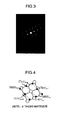
Fig. 3] Fig. 3 shows an electron diffraction pattern from a precipitate and a matrix of No. 1 after treatment A of the invention. - [
Fig. 4] Fig. 4 shows a schematic diagram of the electron diffraction pattern inFig. 3 . - [
Fig. 5] Fig. 5 shows a stereographic projection calculated from the electron diffraction pattern inFig. 3 . - [
Fig. 6] Fig. 6 shows a bright-field image of a nitrided structure obtained through transmission electron microscope observation of No. 1 after treatment B of a comparative example. - [
Fig. 7] Fig. 7 shows an electron diffraction pattern obtained from a precipitate and a matrix of No. 1 after treatment B of the comparative example. - [
Fig. 8] Fig. 8 shows a schematic diagram of the electron diffraction pattern inFig. 7 . - [
Fig. 9] Fig. 9 shows a stereographic projection calculated from the electron diffraction pattern inFig. 7 . - [
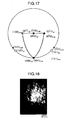
Fig. 10] Fig. 10 shows a bright-field image of a nitrided structure obtained through transmission electron microscope observation of No. 2 after treatment C. - [
Fig. 11] Fig. 11 shows an electron diffraction pattern obtained from a precipitate and a matrix of No. 2 after treatment C. - [
Fig. 12] Fig. 12 shows a schematic diagram of the electron diffraction pattern inFig. 11 . - [
Fig. 13] Fig. 13 shows a stereographic projection calculated from the electron diffraction pattern inFig. 11 . - [
Fig. 14] Fig. 14 shows a bright-field image of a nitrided structure obtained through transmission electron microscope observation of No. 3 after treatment C of the invention. - [
Fig. 15] Fig. 15 shows an electron diffraction pattern obtained from a precipitate and a matrix of No. 3 after treatment C of the invention. - [
Fig. 16] Fig. 16 shows a schematic diagram of the electron diffraction pattern inFig. 15 . - [
Fig. 17] Fig. 17 shows a stereographic projection calculated from the electron diffraction pattern inFig. 15 . - [
Fig. 18] Fig. 18 shows a bright-field image of a nitrided structure obtained through transmission electron microscope observation of No. 4 after treatment C of the invention. - [
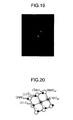
Fig. 19] Fig. 19 shows an electron diffraction pattern obtained from a precipitate and a matrix of No. 4 after treatment C of the invention. - [
Fig. 20] Fig. 20 shows a schematic diagram of the electron diffraction pattern inFig. 19 . - [
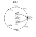
Fig. 21] Fig. 21 shows a stereographic projection calculated from the electron diffraction pattern inFig. 19 . - The invention has been made based on the above new finding. Hereinafter, effect of each element in the invention will be described.
- In a maraging steel of the invention, each chemical element is defined within following range, and the reason therefore is as follows. Please note that contents are described in mass % unless otherwise specified.
- Carbon (C) should be kept low since C forms carbides together with Mo to reduce precipitated intermetallic compounds and decrease strength of the steel. Moreover, positive addition of C increases a risk of deteriorating weldability required for e.g. continuously variable transmission parts. For these reasons, a C content is defined to be 0.01% or less. The C content is preferably 0.008% or less.
- Silicon (Si) makes intermetallic compounds fine during aging treatment and forms intermetallic compounds with Ni so that the element is capable of compensating for decrease in strength caused by reduction of Ti. However, Si content should be kept low to ensure toughness and ductility of the steel in the invention, since Si possibly decreases the toughness. Si content is defined to be 0.1% or less since addition of Si exceeding 0.1% decreases the toughness and ductility. The Si content is preferably 0.05% or less in order to surely ensure the toughness and ductility.
- Manganese (Mn) forms intermetallic compounds with Ni during aging treatment and contributes to age hardening, so that the element is capable of compensating for decrease in strength caused by reduction in Ti. However, Mn content should be kept low to ensure toughness and ductility of the steel in the invention since Mn possibly decreases the toughness. Mn content is defined to be 0.1% or less since addition ofMn exceeding 0.1% decreases the toughness and ductility. The Mn content is preferably 0.05% or less in order to surely ensure the toughness and ductility.
- Phosphor (P) and sulfur (S) segregate at old austenite grain boundaries and form inclusions. Thus, they are detrimental elements since they embrittle the maraging steel and decrease fatigue strength thereof. Therefore, P content is defined to be 0.01% or less, and S content is defined to be 0.005% or less. Preferably, the P content is in a range of 0.005% or less, and the S content is 0.004% or less.
- Chromium (Cr) decreases a nitriding depth, increases nitriding hardness, and increases compression residual stress of a nitrided surface since the element has strong affinity with nitrogen. Thus, addition of Cr is essential for the steel. However, since Cr content of less than 0.1% does not achieve the effects and the Cr content exceeding 8.0% does not achieve further effects and greatly decrease strength of the steel after aging. Therefore, the Cr content is defined to be 0.1 to 8.0%. The Cr content is preferable 0.2% or more and 4.0% or less.
- At least 8.0% of nickel (Ni) is required to stably form a low-C martensitic structure which is a matrix structure of the maraging steel. However, Ni content exceeding 22.0% stabilizes an austenitic structure, and makes it difficult to induce martensite transformation. Thus, the Ni content is defined to be from 8.0 to 22.0%. The preferable range of Ni is 17.0% or more and 22.0% or less.
- Molybdenum (Mo) is an important element for the steel since the element forms fine intermetallic compounds such as Ni3Mo and Fe2Mo during aging treatment and contributes to precipitation hardening. Moreover, Mo is effective for increasing surface hardness and compression residual stress due to nitriding. Mo content of less than 2.0% makes tensile strength of the steel insufficient, and Mo content exceeding 10.0% facilitates formation of coarse intermetallic compounds composed mainly of Fe and Mo. Thus, the Mo content is defined to be from 2.0 to 10.0%. The preferable range of Mo is 3.0% or more and 7.0% or less.
- Cobalt (Co) is an important element since it promotes precipitation of fine intermetallic compounds containing Mo and Al, and contributes to aging precipitation hardening. Co increases degree of solid solution of aging precipitate-forming elements such as Mo and Al at a solid solution treatment temperature, and decreases degree of solid solution of Mo and Al at an aging precipitation temperature, without exerting a great influence on stability of a martensitic structure of the matrix of the steel. Although much Co content is necessary to be added from a viewpoint of strength and toughness, if the Co content is less than 2.0%, the maraging steel having reduced Si, Mn and Ti has difficulty in obtaining sufficient strength. On the other hand, if the Co content exceeds 20.0, Co makes austenite stable to make it difficult to obtain a martensitic structure. Thus, the Co content is defined to be from 2.0% to 20.0%. Preferable range of Co is 4.0% or more and 20.0% or less.
- In a case of limiting aluminum (Al), it is preferable that cobalt (Co) content is slightly increased since Al contributing to strengthening of the steel is decreased. Therefore, the Co content range is 10.0% or more and 20.0% or less.
- Titanium (Ti) is one of essential elements for hardening the maraging steel. However, Ti is a detrimental element at the same time since it forms inclusions such as TiN or Ti(C, N), thereby decreases fatigue strength of the steel particularly in an ultra-high cycle region. Therefore, in a case of placing importance on the fatigue strength, Ti is necessary to be kept low as an impurity level.
- Ti tends to form a thin and stable oxide film on a surface of the steel. The oxide film hinders nitriding reaction, and therefore makes it difficult to obtain a sufficient compression residual stress on a nitrided surface. Ti is a detrimental impurity element, and the content thereof is necessary to be kept low in order to facilitate nitriding and to increase the compression residual stress on the surface after nitriding.
- Ti content is defined to be 0.1% or less since Ti content of more than 0.1% does not produce sufficient effect of reducing TiN or Ti(C, N), and facilitates formation of the stable oxide film on the surface of the steel. The Ti content is preferably 0.05% or less, and further preferably 0.01% or less.
- Regarding aluminum (Al), there are two cases in the invention: one is positive addition of Al; and the other is restriction thereof.
- The positive addition of Al may improve strength of the maraging steel. Therefore, when importance is placed on the strength, Al is preferably added.
- Al is usually added in a small amount for deoxidation, and essentially forms intermetallic compounds with Ni during aging treatment and contributes to strengthening. Since the maraging steel for a metallic belt of the invention has reduced Si, Mn and Ti, Al may compensate strength. Moreover, an effect may be also expected that a good nitrided layer is obtained by facilitating nitriding treatment in the maraging steel with reduced Ti.
- However, Al content of more than 2.5% is not preferable since much AlN and Al2O3 inclusions are formed to decrease fatigue strength, or a thin and stable oxide film is formed on a surface of the steel to hinder nitriding reaction. When Al is added positively, surface roughness of the maraging steel can be somewhat increased. Therefore, the upper limit of positively added Al is 1.5%.
- On the other hand, when the content of Al is restricted, nonmetallic inclusions in the maraging steel may be reduced. Further, surface roughness of the maraging steel is influenced by Al and can be easily kept flat. Therefore, when importance is placed on fatigue strength, it is preferable to restrict Al. According to a study conducted by the inventors, specific nitrided structure is effective in further improving fatigue strength which has been improved by lowing Al. For purpose of increasing the fatigue strength, Al content is restricted to less than 0.1%, and preferably to 0.05% or less.
- Moreover, it is effective to keep total amount of Al and Ti low to improve the fatigue strength since both of Al and Ti form nonmetallic inclusions. Therefore, it is desirable that a total amount of Al and Ti (Al+Ti) is 0.1% or less. The preferable range of the Al+Ti content is 0.07% or less.
- Nitrogen (N) is an impurity element that is combined with Ti to form inclusions of TiN or Ti(C, N) and decreases fatigue strength particularly in ultra-high cycle region. For a maraging steel containing Ti, the content ofN is necessary to be kept significantly low to prevent formation of coarse TiN or Ti(C, N). However, for a maraging steel scarcely containing Ti, the N content is defined to be 0.03% or less since an amount ofN mixed in usual vacuum melting exerts a little adverse influence. Desirably, the N content is 0.01% or less. Further desirably, the N content is 0.005% or less.
- Oxygen (O) is an impurity element that forms oxide-based inclusions and thereby decreases toughness and fatigue strength of the steel. Therefore, content of O is restricted to 0.005% or less. Desirably, the O content is 0.003% or less.
- In the invention, one or more of Ca: 0.01% or less, Mg: 0.005% or less, and B: 0.01% or less may be contained.
- An ingot of the maraging steel of the invention may be produced by melting in a vacuum atmosphere, such as by vacuum induction melting or by vacuum induction melting followed by vacuum arc remelting or electroslag remelting. However, even when such melting in the vacuum atmosphere is performed, it is technically difficult to completely eliminate nonmetallic inclusions.
- Since the steel of the invention may contain Al to improve strength of the steel, there are risks of formation of coarse and hard Al2O3 inclusions exceeding e.g. 25µm, or of occurrence of clustered Al2O3. The Al2O3 inclusions have high hardness and high melting point, and are scarcely deformed, e.g., even during hot plastic working. Thereby, they may generate a flaw on a roll e.g. during cold rolling so that surface defect may be generated on the maraging steel for a metallic belt. Therefore, it is preferable that the Al2O3 inclusions be made composite inclusions combined with other oxides to decrease hardness and lower melting point thereof. Moreover, an element capable of preventing occurrence of the cluster is preferably added for preventing inclusion defects.
- Silicon (Si), manganese (Mn), calcium (Ca) and magnesium (Mg) are raised as the effective elements for making Al2O3 composite inclusions. In the invention, amounts of addition of Si and Mn are restricted since Si and Mn reduces toughness and ductility. Therefore, one or more of Ca and Mg other than Si and Mn may be added in the steel to make the Al2O3 inclusions be composite inclusions. Ca and Mg also have an effect of preventing occurrence of cluster of Al2O3 inclusions. Therefore, the steel of the invention contains Ca: 0.01% or less and/or Mg: 0.005% or less.
- To surely achieve the effects of Ca and Mg, the lower limit of content may be preferably 0.001% for Ca and 0.0001% for Mg.
- Boron (B) is an element that makes old austenitic grains fine at the time of solid solution treatment after cold working and contributes to strengthening. B further has an effect of restraining roughness of a surface of the steel. Therefore, B may be optionally added. B content is defined to be 0.01% or less since the B content of more than 0.01% decreases toughness of the steel. The B content is desirably 0.005% or less. The preferable lower limit of the B content capable of surely making the old austenitic grains fine is 0.0002%.
- The balance other than the above described elements is iron (Fe) and unavoidable impurities.
- However, the steel may contain following element in following range for the purpose of deoxidation, desulfurization and the like.

- As described above, the maraging steel strip of the invention has an important advantage in that the maraging steel strip is adjusted to have an unconventional nitrided structure in which a substantial Baker-Nutting orientation relationship exists between Cr nitride and matrix martensite after nitriding treatment. Such a specific nitrided structure realizes further improvement of fatigue properties.
- The Baker-Nutting orientation relationship herein means that the nitrided structure and the matrix of the invention satisfy following relationships,


- The inventors found that the slight change in a nitriding treatment condition for a maraging steel strip containing Cr led to significantly improved fatigue strength, and pursued causes thereof. As a result, the inventors found that, in nitriding treatment, Baker-Nutting orientation relationship may be established between chromium nitride (CrN) precipitated on a surface of a maraging steel strip containing Cr and a matrix, and then the steel may have significantly improved fatigue strength due to precipitation hardening effect. Since this relationship tends to be very easily disrupted due to a variation of the nitriding condition, it is required to carefully select the condition depending on steel grade.
- In the invention, it is defined that the Cr nitride and the matrix martensite satisfy Baker-Nutting orientation relationship with an orientation difference within 10°, in order to specifically represent that substantial Baker-Nutting orientation relationship exists between the Cr nitride and the matrix martensite. When the orientation difference of the orientation relationship is larger than 10°, the precipitation hardening effect can not be expected.
- The maraging steel of the invention scarcely contains Ti since Ti forms on the surface of the steel a stable oxide film having a possibility of hindering nitriding. Therefore, it can be easily subjected to various types of nitriding treatment, such as usual gas nitriding, gas nitrocarburizing, nitrosulphurizing, ion nitriding, and salt bath nitriding.
- In order to realize the above nitrided structure in the invention, an appropriate solid solution treatment temperature is also important in addition to the composition of the maraging steel strip and the nitriding condition as described above. In the invention, the solid solution treatment temperature is increased to 850 to 950°C to increase solid solubility of Cr in the alloy. This is because solid solubility of Cr tends to be insufficient when the solid solution treatment temperature is less than 850°C, and this makes it difficult to obtain the nitrided structure defined in the invention. On the other hand, when the solid solution treatment temperature is more than 950°C, grain coarsening occurs. Therefore, the solid solution treatment temperature is defined to be from 850 to 950°C.
- Nitriding treatment temperature may range from 450 to 500°C, e.g., in the case of gas nitrocarburizing. Treating time is particularly important. The nitrided structure is sensitive to the treating time. The nitriding treatment temperature particularly changes since the various types of nitriding treatment may be applied as the nitriding treatment as described above. Therefore, it is preferred to check a nitrided structure by changing the treating time, after high temperature solid solution treatment, in order to obtain the nitrided structure of the invention in mass production.
- In the maraging steel for a metallic belt to which the above maraging steel strip of the invention is applied, absolute value of compression residual stress of a nitrided layer may be increased by Cr and Al that have an effect of enhancing the nitriding hardness and the absolute value of compression residual stress of the nitrided layer, although the compression residual stress tends to decrease.
- The maraging steel strip for a metallic belt of the invention has a high tensile strength and fatigue strength, and is suitable for a metallic belt for a continuously variable transmission of automobile engines since it has excellent fatigue properties through the nitriding treatment.
- The invention will be explained in more detail with reference to following Examples.
- Maraging steel having a composition defined in the invention was melted in a vacuum induction melting furnace to produce an ingot of 10 kg, and the ingot was subjected to homogenizing anneal, and then hot forged. Further, steel strips having a thickness of about 0.2 mm were produced by hot rolling and cold rolling, thereby maraging steels for a metallic belt were produced. The chemical composition thereof is shown in Table 1.
- Thereafter, the steel strip was subjected to solid solution treatment at 900°C, and further, aging treatment at 490°C. As nitriding treatment, gas nitrocarburizing was performed under conditions at 460°C for 35 minutes as treatment A, and at 460°C for 50 minutes as treatment B for clearly representing the change of a nitrided structure. The solid solution treatment was performed in a hydrogen atmosphere.
[Table 1] No. Chemical composition (mass%) 1 C Si Mn P S Cr Ni Mo Co Ti Al 0.003 0.01 0.01 0.003 0.001 0.97 19.3 5.1 12.8 0.01 0.03 N O Mg Ca B balance 0.0006 0.0018 0.0019 - 0.0015 Fe and unavoidable impurities Note: Symbol "-" shows no addition. -
Fig. 1 shows a result of measurements of hardness distribution obtained by the treatments A and B. - A longitudinal cross sections of the maraging steel strips for a metallic belt after nitriding treatments were embedded in a thermosetting resin and subjected to mirror polishing, and then the hardness distribution was measured with a micro Vickers hardness meter under a load of 50 g. Surface hardness was measured from surfaces of the maraging steel strips with the micro Vickers hardness meter under a load of 100 g. These show that nitriding depths of Nos. 1 and treatments A and B are 25 µm and 50 µm, respectively.
- For observation of the nitrided structure, a thin film at a location from about 15 to 20 µm in nitriding depth was produced with a Focus Ion Beam device, and subjected to transmission electron microscope observation. The observation was performed using an electron accelerated with 200kV An electron diffraction pattern of a precipitate and a matrix and a stereo analytical method thereof were used for identification of the precipitate and calculation of orientation relationship.
- While fatigue tests include various stress modes such as rotational bending, tension/compression and torsion, a suitable evaluation method is one that applies bending stress since the maraging steel of the invention has a form of a strip. Thus, it will be apparent that the maraging steel has high fatigue strength unless fracture occurs when applying such a high stress that fractures a conventional maraging steel in repeated bending fatigue test. Therefore, the repeated bending fatigue test was performed until a number of cycles reached 107 cycles when a repeated bending stress was applied at an average stress of 617 MPa and a maximum stress of 1176 MPa.
- From
Fig. 2 , a plurality of acicular precipitates were observed in a bright-field image of the treatment A, and found that they have the same orientation. Moreover, it was found that these acicular precipitates were CrN from an analysis of electron diffraction patterns inFigs. 3 and 4 , and that CrN and matrix martensite satisfy Baker-Nutting orientation relationship since they are parallel, (-100)CrN // (-100)α', and [010]CrN // [0-1-1]α', with an orientation difference of 4° from stereo analysis inFig. 5 . Thus, good lattice coherence was found. - On the other hand, from
Fig. 6 , a plurality of acicular precipitates were also observed in a bright-field image of the treatment B. However, they were coarser than the precipitates observed in the treatment A. Moreover, it was found that these acicular precipitates were CrN from an analysis of electron diffraction patterns inFigs. 7 and 8 , and a deviation from Baker-Nutting orientation with an orientation difference of 14° was recognized between CrN and matrix martensite from a result of stereo analysis inFig. 9 . Thus, poor lattice coherence was found. - Table 2 shows a result of repeat bending test. This shows that No.1 and treatment A maraging steel for a metallic belt with coherent CrN precipitated in a nitrided structure did not fracture until 107 cycles in the repeat bending test under maximum stress of 1176 MPa. On the other hand, all of No.1 and treatment B, maraging steels fractured at 106 cycles. Therefore, No. 1 after treatment A with the lattice coherent CrN precipitates have excellent fatigue property by the precipitation hardening effect.
- Thus, the maraging steel strip of the invention may realize high fatigue strength by optimizing the nitrided structure.
-
[Table 2] Alloy No. Treatment Nitriding depth (µm) Number of cycles until failure (cycles) 1 A 25µm 107 (No failure) 107 (No failure) B 50µm 1268800 2773500 Note: Fatigue test was performed at maximum stress of 1176 MPa, and at average stress of 617 MPa - In Example 2, effect of composition was investigated.
- Nos.3 to 4 maraging steels having composition ranges according to the invention, No 2 Reference maraging steel and No.5 maraging steel which was a comparative material having a conventional composition were melted in a vacuum induction melting furnace to produce ingots of 10 kg, and the ingots were subjected to homogenizing anneal, and then hot forged. Further, steel strips each having a thickness of about 0.2 mm were produced by hot rolling and cold rolling. thus, maraging steels for a metallic belt were produced. Their chemical compositions are shown in Table 3.
[Table 3] No. Chemical composition (mass%) C Si Mn P S Cr Ni Mo Co Ti Al 2* 0.003 0.01 0.01 0.001 0.001 0.47 18.7 5.0 12.5 0.001 0.04 N O Mg Ca B balance 0.0008 0.0107 - - - Fe and unavoidable impurities C Si Mn P S Cr Ni Mo Co Ti Al 3 0.003 0.01 0.01 0.002 0.002 1.43 19.1 5.1 12.4 0.001 0.03 N O Mg Ca B balance 0.0005 0.0017 0.0024 - 0.0012 Fe and unavoidable impurities C Si Mn P S Cr Ni Mo Co Ti Al 4 0.004 0.01 0.01 0.003 0.001 0.94 19.0 5.0 10.0 0.001 0.49 N O Mg Ca B balance 0.0003 0.0005 . 0.0028 0.0002 0.0013 Fe and unavoidable impurities C Si Mn P S Cr Ni Mo Co Ti Al 5 0.004 0.01 0.01 0.001 0.001 - 18.6 5.1 9.4 0.49 0.11 N O Mg Ca B balance 0.0004 0.0021 0.0020 - 0.0001 Fe and unavoidable impurities Note: Symbol "-" shows no addition.
* Reference steel - The above maraging steels for a metallic belt Nos.1 to 4 were subjected to solid solution treatment at 900°C, and the steel No. 5 was subjected to solid solution treatment at 850°C. Further, the steels were subjected to aging treatment at 490°C, and thereafter nitrocarburizing under a condition at 460°C for 40 minutes as treatment C. The solid solution treatment was performed in a hydrogen atmosphere.
- For observation of nitrided structure, a thin film at a location from about 15 to 20 µm in nitriding depth was produced with a Focus Ion Beam device, and subjected to transmission electron microscope observation. The observation was performed using an electron accelerated with 200kV An electron diffraction pattern of a precipitate and a matrix and a stereo analytical method thereof were used for identification of the precipitate and calculation of orientation relationship. The identification of the precipitate and the orientation relationship were performed with respect to Nos. 3 and 4 of the invention, and Reference steel No 2.
-
Fig. 10 shows a bright-field image of the Reference steel No.2. A plurality of acicular precipitates were observed in a bright-field image of the Reference steel No.2 after treatment C, and they have the same orientation. Moreover, it was found that all of these acicular precipitates were CrN from an analysis of electron diffraction pattern inFig. 11 and 12 . - Baker-Nutting orientation relationship was investigated with stereo analysis in
Fig. 13 . CrN and matrix martensite satisfy the Baker-Nutting orientation relationship since they are in parallel relationships, (100)CrN // (-101)α', and [010]CrN // [0-10]α', with an orientation difference of 6°. Thus, good lattice coherence was found. -
Fig. 14 shows a bright-field image of the steel No.3. A plurality of acicular precipitates were observed in a bright-field image of No. 3 after treatment C, and found that they have the same orientation. Moreover, all of the acicular precipitates were CrN from an analysis of electron diffraction patterns inFigs. 15 and 16 . - Baker-Nutting orientation relationship was investigated with stereo analysis in
Fig. 17 . CrN and matrix martensite satisfy the Baker-Nutting orientation relationship since they are in parallel relationships, (100)CrN // (-1-1)α', and [0-10]CrN // [0-11]α', with an orientation difference of 2°. Thus, good lattice coherence was found. -
Fig. 18 shows a bright-field image of the steel No.4. A plurality of acicular precipitates were observed in a bright-field image of No.4 after treatment C, and found that they are directed in the same orientation. Moreover, all of the acicular precipitates were CrN from an analysis of electron diffraction patterns inFigs. 19 and 20 . - Baker-Nutting orientation relationship was investigated with stereo analysis in
Fig. 21 . CrN and matrix martensite satisfy the Baker-Nutting orientation relationship since they are in parallel relationships, (100)CrN // (-1-10)α', and [0-10]CrN // [1-10]α', with an orientation difference of 5°. Thus, good lattice coherence was found. - Fatigue test was performed by the repeat bending test in the same manner as Example 1. However, the repeat bending test was performed under a higher stress, that is an average stress of 729 MPa and a maximum stress of 1399 MPa, so as to ensure occurrence of fracture in the maraging steel strip. At this time, the maraging steel strip of the invention of No. 1 after treatment A in the above Example 1 was also subjected to the repeat bending test. Table 4 shows a result of the repeat bending tests.
- It was confirmed from Table 4 that the maraging steels for a metallic belt of Nos. 1, 3 and 4 of the invention with the coherent CrN precipitates in the nitrided structure had excellent fatigue property due to the precipitation hardening effect, compared with the comparative steel No. 5 which does not CrN precipitates.
- Among them, the maraging steel strips having low Al were found to obtain high fatigue strength regardless of the repeat bending test under a high stress condition.
[Table 4] Alloy No. Treatment Number of cycles until failure (cycles) Remarks 1 A 348700 The invention 352800 2 C 1004500 Reference steel 1330900 3 C 299800 The invention 448000 4 C 78700 The invention 210500 5 C 47400 Comparative example 93900 Note: Fatigue test was performed at maximum stress of 1399 MPa, and at average stress of 729 MPa. - Each fractured surface of Nos. 1 to 4 maraging steel strips in Table 4 was observed after the fatigue test. The fracture was not starting from inclusions such as TiN and Ti(C, N) but occurred due to surface defect created in the test.
- Accordingly, it is found that the maraging steel strip of the invention cay improve bending fatigue strength by optimizing the nitrided structure after nitriding treatment.
- The maraging steel strip of the invention can be used for a metallic belt used under stringent conditions, and therefore can be applied to members required to have high tensile strength and high fatigue strength, such as a power transmission metallic belt used in continuously variable transmissions for automobiles and the like.
Claims (2)
- A nitrided maraging steel strip comprising a nitrided layer on a surface of a steel consisting of, by mass %,
C: 0.01% or less,
Si: 0.1% or less,
Mn: 0.1% or less,
P: 0.01% or less,
S: 0.005% or less,
Ni: 8.0 to 22.0%,
Cr: 0.1 to 8.0%,
Mo: 2.0 to 10.0%,
Co: 2.0% to 20.0%,
Ti: 0.1% or less,
Al: 2.5% or less,
N: 0.03% or less,
O: 0.005% or less,
optionally one or more of Ca: 0.01% or less, Mg: 0.005% or less, and B: 0.01% or less,
optionally Zr: 0.01 % or less, and
the balance being Fe and unavoidable impurities,
the nitrided layer comprising Cr nitride precipitated in the nitrided layer and a matrix martensite,
characterised in that the Cr nitride and the matrix martensite satisfy the Baker-Nutting orientation relationship with an orientation difference within 10°. - The maraging steel strip according to claim 1, wherein the maraging steel strip contains less than 0.1 % of Al, and a total amount of Al+Ti is 0.1 % or less.
Applications Claiming Priority (2)
| Application Number | Priority Date | Filing Date | Title |
|---|---|---|---|
| JP2009077409 | 2009-03-26 | ||
| PCT/JP2010/055258 WO2010110379A1 (en) | 2009-03-26 | 2010-03-25 | Maraging steel strip |
Publications (3)
| Publication Number | Publication Date |
|---|---|
| EP2412836A1 EP2412836A1 (en) | 2012-02-01 |
| EP2412836A4 EP2412836A4 (en) | 2012-08-29 |
| EP2412836B1 true EP2412836B1 (en) | 2014-12-17 |
Family
ID=42781070
Family Applications (1)
| Application Number | Title | Priority Date | Filing Date |
|---|---|---|---|
| EP10756175.5A Active EP2412836B1 (en) | 2009-03-26 | 2010-03-25 | Maraging steel strip |
Country Status (6)
| Country | Link |
|---|---|
| US (1) | US8747574B2 (en) |
| EP (1) | EP2412836B1 (en) |
| JP (1) | JP5429651B2 (en) |
| CN (1) | CN102356171A (en) |
| MX (1) | MX2011009958A (en) |
| WO (1) | WO2010110379A1 (en) |
Families Citing this family (15)
| Publication number | Priority date | Publication date | Assignee | Title |
|---|---|---|---|---|
| EP2265739B1 (en) | 2008-04-11 | 2019-06-12 | Questek Innovations LLC | Martensitic stainless steel strengthened by copper-nucleated nitride precipitates |
| US10351922B2 (en) * | 2008-04-11 | 2019-07-16 | Questek Innovations Llc | Surface hardenable stainless steels |
| CN103827334B (en) * | 2011-09-30 | 2016-08-17 | 日立金属株式会社 | Maraging steel |
| CN102517541B (en) * | 2011-12-19 | 2013-07-10 | 台州市百达热处理有限公司 | Gas nitriding treatment method of 11Cr17 stainless steel slip sheet |
| JP6166953B2 (en) * | 2012-06-06 | 2017-07-19 | 大同特殊鋼株式会社 | Maraging steel |
| CN104919666B (en) * | 2013-01-08 | 2016-08-24 | 日本特殊陶业株式会社 | Electrode material and spark plug |
| JP6653113B2 (en) | 2013-08-23 | 2020-02-26 | 大同特殊鋼株式会社 | Maraging steel with excellent fatigue properties |
| US9745736B2 (en) * | 2013-08-27 | 2017-08-29 | University Of Virginia Patent Foundation | Three-dimensional space frames assembled from component pieces and methods for making the same |
| CN103820729B (en) * | 2014-03-14 | 2017-05-03 | 钢铁研究总院 | Titanium reinforced high-cobalt martensitic aged anti-corrosion ultrahigh-strength steel and preparation method |
| NL1041102B1 (en) * | 2014-12-17 | 2016-10-11 | Bosch Gmbh Robert | Flexible steel ring for a drive belt for a continuously variable transmission and method for producing such. |
| WO2017064537A1 (en) * | 2015-10-15 | 2017-04-20 | Aperam | Steel, product created from said steel, and manufacturing method thereof |
| CN106756583A (en) * | 2015-11-25 | 2017-05-31 | 中国科学院金属研究所 | A kind of ultra-high-strength/tenacity Maraging steel and its preparation method and application |
| JP2017218634A (en) * | 2016-06-08 | 2017-12-14 | 株式会社神戸製鋼所 | Maraging steel |
| DE102017131219A1 (en) * | 2017-12-22 | 2019-06-27 | Voestalpine Böhler Edelstahl Gmbh & Co Kg | A method of making an article from a maraging steel |
| JP7172080B2 (en) * | 2018-03-23 | 2022-11-16 | 日立金属株式会社 | Maraging steel for metal belts |
Family Cites Families (13)
| Publication number | Priority date | Publication date | Assignee | Title |
|---|---|---|---|---|
| GB1142555A (en) * | 1966-08-25 | 1969-02-12 | Int Nickel Ltd | Nickel-cobalt steels |
| JPH10152759A (en) * | 1996-11-21 | 1998-06-09 | Daido Steel Co Ltd | Maraging steel excellent in toughness |
| JP4427772B2 (en) | 1999-12-24 | 2010-03-10 | 日立金属株式会社 | Maraging steel with high fatigue strength and maraging steel strip using it |
| EP1111080B1 (en) * | 1999-12-24 | 2007-03-07 | Hitachi Metals, Ltd. | Maraging steel having high fatigue strength and maraging steel strip made of same |
| FR2816959B1 (en) | 2000-11-17 | 2003-08-01 | Imphy Ugine Precision | PROCESS FOR MANUFACTURING A STRIP OR A CUT PIECE IN A COLD-ROLLED MARAGING STEEL STRIP |
| JP2002167652A (en) | 2000-11-28 | 2002-06-11 | Daido Steel Co Ltd | Thin sheet material excellent in high strength-high fatigue resisting characteristic |
| JP3677460B2 (en) | 2001-04-06 | 2005-08-03 | 本田技研工業株式会社 | Steel manufacturing method |
| JP4613698B2 (en) | 2005-05-26 | 2011-01-19 | 大同特殊鋼株式会社 | Steel strip and strip |
| JP5007930B2 (en) | 2005-12-13 | 2012-08-22 | 日立金属株式会社 | Maraging steel having high fatigue strength, maraging steel strip using the same, and method for producing maraging steel having high fatigue strength |
| JP5046363B2 (en) | 2005-12-13 | 2012-10-10 | 日立金属株式会社 | Maraging steel for power transmission belt with high fatigue strength and maraging steel strip for power transmission belt using the same |
| JP5053651B2 (en) * | 2007-01-31 | 2012-10-17 | 日立金属株式会社 | Method for producing maraging steel strip having high fatigue strength |
| JP2009013464A (en) * | 2007-07-04 | 2009-01-22 | Hitachi Metals Ltd | Maraging steel for metal belt |
| EP2180073B1 (en) * | 2007-07-11 | 2013-09-11 | Hitachi Metals, Ltd. | Maraging steel for metallic belt |
-
2010
- 2010-03-25 MX MX2011009958A patent/MX2011009958A/en active IP Right Grant
- 2010-03-25 CN CN201080012255XA patent/CN102356171A/en active Pending
- 2010-03-25 EP EP10756175.5A patent/EP2412836B1/en active Active
- 2010-03-25 WO PCT/JP2010/055258 patent/WO2010110379A1/en active Application Filing
- 2010-03-25 JP JP2011506118A patent/JP5429651B2/en active Active
- 2010-03-25 US US13/259,897 patent/US8747574B2/en active Active
Also Published As
| Publication number | Publication date |
|---|---|
| EP2412836A4 (en) | 2012-08-29 |
| MX2011009958A (en) | 2011-10-06 |
| WO2010110379A1 (en) | 2010-09-30 |
| US20120031529A1 (en) | 2012-02-09 |
| CN102356171A (en) | 2012-02-15 |
| EP2412836A1 (en) | 2012-02-01 |
| JP5429651B2 (en) | 2014-02-26 |
| JPWO2010110379A1 (en) | 2012-10-04 |
| US8747574B2 (en) | 2014-06-10 |
Similar Documents
| Publication | Publication Date | Title |
|---|---|---|
| EP2412836B1 (en) | Maraging steel strip | |
| EP3530769B1 (en) | Martensitic stainless steel sheet | |
| KR101464712B1 (en) | Steel component having excellent temper softening resistance | |
| EP3276040B1 (en) | Nitrided or soft nitrided part with excellent wear resistance and pitting resistance | |
| EP1111080B1 (en) | Maraging steel having high fatigue strength and maraging steel strip made of same | |
| EP2180073B1 (en) | Maraging steel for metallic belt | |
| KR102624515B1 (en) | Steel, products made from the steel, and methods of manufacturing the same | |
| CN114807776A (en) | Steel, product made of said steel and method for manufacturing same | |
| EP3524708A1 (en) | Nitrided component and method for producing same | |
| JP5046363B2 (en) | Maraging steel for power transmission belt with high fatigue strength and maraging steel strip for power transmission belt using the same | |
| EP2762586B1 (en) | Maraging steel | |
| KR20190022801A (en) | Nitrided parts and method for manufacturing the same | |
| JP5007930B2 (en) | Maraging steel having high fatigue strength, maraging steel strip using the same, and method for producing maraging steel having high fatigue strength | |
| JP2009013464A (en) | Maraging steel for metal belt | |
| EP2868764A1 (en) | Steel sheet for soft nitriding and process for producing same | |
| JP4451919B1 (en) | Steel sheet and manufacturing method thereof, and steel belt for continuously variable transmission | |
| EP4265784A1 (en) | Martensitic stainless steel with improved strength and corrosion resistance, and manufacturing method therefor | |
| JP4507149B2 (en) | Maraging steel for power transmission belt with high fatigue strength and maraging steel strip for power transmission belt using the same | |
| WO2021181570A1 (en) | Gas soft-nitriding processed article and method of producing same | |
| JP2001240943A (en) | Maraging steel with high fatigue strength, and maraging steel strip using it | |
| JP7172080B2 (en) | Maraging steel for metal belts |
Legal Events
| Date | Code | Title | Description |
|---|---|---|---|
| PUAI | Public reference made under article 153(3) epc to a published international application that has entered the european phase |
Free format text: ORIGINAL CODE: 0009012 |
|
| 17P | Request for examination filed |
Effective date: 20111020 |
|
| AK | Designated contracting states |
Kind code of ref document: A1 Designated state(s): AT BE BG CH CY CZ DE DK EE ES FI FR GB GR HR HU IE IS IT LI LT LU LV MC MK MT NL NO PL PT RO SE SI SK SM TR |
|
| DAX | Request for extension of the european patent (deleted) | ||
| A4 | Supplementary search report drawn up and despatched |
Effective date: 20120801 |
|
| RIC1 | Information provided on ipc code assigned before grant |
Ipc: C22C 38/06 20060101ALI20120726BHEP Ipc: C23C 8/26 20060101ALI20120726BHEP Ipc: C22C 38/50 20060101ALI20120726BHEP Ipc: C21D 9/40 20060101ALI20120726BHEP Ipc: C22C 38/52 20060101ALI20120726BHEP Ipc: C21D 9/46 20060101ALI20120726BHEP Ipc: C21D 1/06 20060101ALI20120726BHEP Ipc: C22C 38/54 20060101ALI20120726BHEP Ipc: C22C 38/44 20060101ALI20120726BHEP Ipc: C22C 38/00 20060101AFI20120726BHEP Ipc: C21D 6/02 20060101ALI20120726BHEP |
|
| RIC1 | Information provided on ipc code assigned before grant |
Ipc: C22C 38/06 20060101ALI20140428BHEP Ipc: C23C 8/26 20060101ALI20140428BHEP Ipc: C22C 38/54 20060101ALI20140428BHEP Ipc: C22C 38/44 20060101ALI20140428BHEP Ipc: C22C 38/50 20060101ALI20140428BHEP Ipc: C21D 1/06 20060101ALI20140428BHEP Ipc: C21D 9/40 20060101ALI20140428BHEP Ipc: C21D 9/46 20060101ALI20140428BHEP Ipc: C21D 6/02 20060101ALI20140428BHEP Ipc: C22C 38/00 20060101AFI20140428BHEP Ipc: C22C 38/52 20060101ALI20140428BHEP |
|
| GRAP | Despatch of communication of intention to grant a patent |
Free format text: ORIGINAL CODE: EPIDOSNIGR1 |
|
| INTG | Intention to grant announced |
Effective date: 20140702 |
|
| GRAS | Grant fee paid |
Free format text: ORIGINAL CODE: EPIDOSNIGR3 |
|
| GRAA | (expected) grant |
Free format text: ORIGINAL CODE: 0009210 |
|
| AK | Designated contracting states |
Kind code of ref document: B1 Designated state(s): AT BE BG CH CY CZ DE DK EE ES FI FR GB GR HR HU IE IS IT LI LT LU LV MC MK MT NL NO PL PT RO SE SI SK SM TR |
|
| REG | Reference to a national code |
Ref country code: GB Ref legal event code: FG4D |
|
| REG | Reference to a national code |
Ref country code: CH Ref legal event code: EP |
|
| REG | Reference to a national code |
Ref country code: IE Ref legal event code: FG4D |
|
| REG | Reference to a national code |
Ref country code: AT Ref legal event code: REF Ref document number: 702002 Country of ref document: AT Kind code of ref document: T Effective date: 20150115 |
|
| REG | Reference to a national code |
Ref country code: DE Ref legal event code: R096 Ref document number: 602010021100 Country of ref document: DE Effective date: 20150129 |
|
| REG | Reference to a national code |
Ref country code: NL Ref legal event code: T3 |
|
| PG25 | Lapsed in a contracting state [announced via postgrant information from national office to epo] |
Ref country code: LT Free format text: LAPSE BECAUSE OF FAILURE TO SUBMIT A TRANSLATION OF THE DESCRIPTION OR TO PAY THE FEE WITHIN THE PRESCRIBED TIME-LIMIT Effective date: 20141217 Ref country code: NO Free format text: LAPSE BECAUSE OF FAILURE TO SUBMIT A TRANSLATION OF THE DESCRIPTION OR TO PAY THE FEE WITHIN THE PRESCRIBED TIME-LIMIT Effective date: 20150317 Ref country code: FI Free format text: LAPSE BECAUSE OF FAILURE TO SUBMIT A TRANSLATION OF THE DESCRIPTION OR TO PAY THE FEE WITHIN THE PRESCRIBED TIME-LIMIT Effective date: 20141217 |
|
| REG | Reference to a national code |
Ref country code: LT Ref legal event code: MG4D |
|
| PG25 | Lapsed in a contracting state [announced via postgrant information from national office to epo] |
Ref country code: SE Free format text: LAPSE BECAUSE OF FAILURE TO SUBMIT A TRANSLATION OF THE DESCRIPTION OR TO PAY THE FEE WITHIN THE PRESCRIBED TIME-LIMIT Effective date: 20141217 Ref country code: HR Free format text: LAPSE BECAUSE OF FAILURE TO SUBMIT A TRANSLATION OF THE DESCRIPTION OR TO PAY THE FEE WITHIN THE PRESCRIBED TIME-LIMIT Effective date: 20141217 Ref country code: LV Free format text: LAPSE BECAUSE OF FAILURE TO SUBMIT A TRANSLATION OF THE DESCRIPTION OR TO PAY THE FEE WITHIN THE PRESCRIBED TIME-LIMIT Effective date: 20141217 Ref country code: GR Free format text: LAPSE BECAUSE OF FAILURE TO SUBMIT A TRANSLATION OF THE DESCRIPTION OR TO PAY THE FEE WITHIN THE PRESCRIBED TIME-LIMIT Effective date: 20150318 |
|
| REG | Reference to a national code |
Ref country code: AT Ref legal event code: MK05 Ref document number: 702002 Country of ref document: AT Kind code of ref document: T Effective date: 20141217 |
|
| PG25 | Lapsed in a contracting state [announced via postgrant information from national office to epo] |
Ref country code: CZ Free format text: LAPSE BECAUSE OF FAILURE TO SUBMIT A TRANSLATION OF THE DESCRIPTION OR TO PAY THE FEE WITHIN THE PRESCRIBED TIME-LIMIT Effective date: 20141217 Ref country code: RO Free format text: LAPSE BECAUSE OF FAILURE TO SUBMIT A TRANSLATION OF THE DESCRIPTION OR TO PAY THE FEE WITHIN THE PRESCRIBED TIME-LIMIT Effective date: 20141217 Ref country code: EE Free format text: LAPSE BECAUSE OF FAILURE TO SUBMIT A TRANSLATION OF THE DESCRIPTION OR TO PAY THE FEE WITHIN THE PRESCRIBED TIME-LIMIT Effective date: 20141217 Ref country code: ES Free format text: LAPSE BECAUSE OF FAILURE TO SUBMIT A TRANSLATION OF THE DESCRIPTION OR TO PAY THE FEE WITHIN THE PRESCRIBED TIME-LIMIT Effective date: 20141217 Ref country code: SK Free format text: LAPSE BECAUSE OF FAILURE TO SUBMIT A TRANSLATION OF THE DESCRIPTION OR TO PAY THE FEE WITHIN THE PRESCRIBED TIME-LIMIT Effective date: 20141217 |
|
| PG25 | Lapsed in a contracting state [announced via postgrant information from national office to epo] |
Ref country code: PL Free format text: LAPSE BECAUSE OF FAILURE TO SUBMIT A TRANSLATION OF THE DESCRIPTION OR TO PAY THE FEE WITHIN THE PRESCRIBED TIME-LIMIT Effective date: 20141217 Ref country code: IS Free format text: LAPSE BECAUSE OF FAILURE TO SUBMIT A TRANSLATION OF THE DESCRIPTION OR TO PAY THE FEE WITHIN THE PRESCRIBED TIME-LIMIT Effective date: 20150417 Ref country code: AT Free format text: LAPSE BECAUSE OF FAILURE TO SUBMIT A TRANSLATION OF THE DESCRIPTION OR TO PAY THE FEE WITHIN THE PRESCRIBED TIME-LIMIT Effective date: 20141217 |
|
| REG | Reference to a national code |
Ref country code: DE Ref legal event code: R097 Ref document number: 602010021100 Country of ref document: DE |
|
| PLBE | No opposition filed within time limit |
Free format text: ORIGINAL CODE: 0009261 |
|
| STAA | Information on the status of an ep patent application or granted ep patent |
Free format text: STATUS: NO OPPOSITION FILED WITHIN TIME LIMIT |
|
| PG25 | Lapsed in a contracting state [announced via postgrant information from national office to epo] |
Ref country code: LU Free format text: LAPSE BECAUSE OF FAILURE TO SUBMIT A TRANSLATION OF THE DESCRIPTION OR TO PAY THE FEE WITHIN THE PRESCRIBED TIME-LIMIT Effective date: 20150325 Ref country code: DK Free format text: LAPSE BECAUSE OF FAILURE TO SUBMIT A TRANSLATION OF THE DESCRIPTION OR TO PAY THE FEE WITHIN THE PRESCRIBED TIME-LIMIT Effective date: 20141217 Ref country code: MC Free format text: LAPSE BECAUSE OF FAILURE TO SUBMIT A TRANSLATION OF THE DESCRIPTION OR TO PAY THE FEE WITHIN THE PRESCRIBED TIME-LIMIT Effective date: 20141217 |
|
| REG | Reference to a national code |
Ref country code: CH Ref legal event code: PL |
|
| 26N | No opposition filed |
Effective date: 20150918 |
|
| GBPC | Gb: european patent ceased through non-payment of renewal fee |
Effective date: 20150325 |
|
| PG25 | Lapsed in a contracting state [announced via postgrant information from national office to epo] |
Ref country code: IT Free format text: LAPSE BECAUSE OF FAILURE TO SUBMIT A TRANSLATION OF THE DESCRIPTION OR TO PAY THE FEE WITHIN THE PRESCRIBED TIME-LIMIT Effective date: 20141217 |
|
| REG | Reference to a national code |
Ref country code: IE Ref legal event code: MM4A |
|
| PG25 | Lapsed in a contracting state [announced via postgrant information from national office to epo] |
Ref country code: LI Free format text: LAPSE BECAUSE OF NON-PAYMENT OF DUE FEES Effective date: 20150331 Ref country code: CH Free format text: LAPSE BECAUSE OF NON-PAYMENT OF DUE FEES Effective date: 20150331 Ref country code: IE Free format text: LAPSE BECAUSE OF NON-PAYMENT OF DUE FEES Effective date: 20150325 Ref country code: GB Free format text: LAPSE BECAUSE OF NON-PAYMENT OF DUE FEES Effective date: 20150325 |
|
| REG | Reference to a national code |
Ref country code: FR Ref legal event code: PLFP Year of fee payment: 7 |
|
| PG25 | Lapsed in a contracting state [announced via postgrant information from national office to epo] |
Ref country code: SI Free format text: LAPSE BECAUSE OF FAILURE TO SUBMIT A TRANSLATION OF THE DESCRIPTION OR TO PAY THE FEE WITHIN THE PRESCRIBED TIME-LIMIT Effective date: 20141217 |
|
| PG25 | Lapsed in a contracting state [announced via postgrant information from national office to epo] |
Ref country code: BE Free format text: LAPSE BECAUSE OF FAILURE TO SUBMIT A TRANSLATION OF THE DESCRIPTION OR TO PAY THE FEE WITHIN THE PRESCRIBED TIME-LIMIT Effective date: 20141217 |
|
| PG25 | Lapsed in a contracting state [announced via postgrant information from national office to epo] |
Ref country code: MT Free format text: LAPSE BECAUSE OF FAILURE TO SUBMIT A TRANSLATION OF THE DESCRIPTION OR TO PAY THE FEE WITHIN THE PRESCRIBED TIME-LIMIT Effective date: 20141217 |
|
| REG | Reference to a national code |
Ref country code: FR Ref legal event code: PLFP Year of fee payment: 8 |
|
| PG25 | Lapsed in a contracting state [announced via postgrant information from national office to epo] |
Ref country code: HU Free format text: LAPSE BECAUSE OF FAILURE TO SUBMIT A TRANSLATION OF THE DESCRIPTION OR TO PAY THE FEE WITHIN THE PRESCRIBED TIME-LIMIT; INVALID AB INITIO Effective date: 20100325 Ref country code: BG Free format text: LAPSE BECAUSE OF FAILURE TO SUBMIT A TRANSLATION OF THE DESCRIPTION OR TO PAY THE FEE WITHIN THE PRESCRIBED TIME-LIMIT Effective date: 20141217 Ref country code: SM Free format text: LAPSE BECAUSE OF FAILURE TO SUBMIT A TRANSLATION OF THE DESCRIPTION OR TO PAY THE FEE WITHIN THE PRESCRIBED TIME-LIMIT Effective date: 20141217 |
|
| PG25 | Lapsed in a contracting state [announced via postgrant information from national office to epo] |
Ref country code: CY Free format text: LAPSE BECAUSE OF FAILURE TO SUBMIT A TRANSLATION OF THE DESCRIPTION OR TO PAY THE FEE WITHIN THE PRESCRIBED TIME-LIMIT Effective date: 20141217 |
|
| PG25 | Lapsed in a contracting state [announced via postgrant information from national office to epo] |
Ref country code: PT Free format text: LAPSE BECAUSE OF FAILURE TO SUBMIT A TRANSLATION OF THE DESCRIPTION OR TO PAY THE FEE WITHIN THE PRESCRIBED TIME-LIMIT Effective date: 20150417 |
|
| PG25 | Lapsed in a contracting state [announced via postgrant information from national office to epo] |
Ref country code: TR Free format text: LAPSE BECAUSE OF FAILURE TO SUBMIT A TRANSLATION OF THE DESCRIPTION OR TO PAY THE FEE WITHIN THE PRESCRIBED TIME-LIMIT Effective date: 20141217 |
|
| REG | Reference to a national code |
Ref country code: FR Ref legal event code: PLFP Year of fee payment: 9 |
|
| PG25 | Lapsed in a contracting state [announced via postgrant information from national office to epo] |
Ref country code: MK Free format text: LAPSE BECAUSE OF FAILURE TO SUBMIT A TRANSLATION OF THE DESCRIPTION OR TO PAY THE FEE WITHIN THE PRESCRIBED TIME-LIMIT Effective date: 20141217 |
|
| PGFP | Annual fee paid to national office [announced via postgrant information from national office to epo] |
Ref country code: NL Payment date: 20230215 Year of fee payment: 14 |
|
| PGFP | Annual fee paid to national office [announced via postgrant information from national office to epo] |
Ref country code: FR Payment date: 20230208 Year of fee payment: 14 |
|
| PGFP | Annual fee paid to national office [announced via postgrant information from national office to epo] |
Ref country code: DE Payment date: 20230131 Year of fee payment: 14 |
|
| P01 | Opt-out of the competence of the unified patent court (upc) registered |
Effective date: 20230525 |