EP2412660A1 - Flat tie down point - Google Patents
Flat tie down point Download PDFInfo
- Publication number
- EP2412660A1 EP2412660A1 EP11169269A EP11169269A EP2412660A1 EP 2412660 A1 EP2412660 A1 EP 2412660A1 EP 11169269 A EP11169269 A EP 11169269A EP 11169269 A EP11169269 A EP 11169269A EP 2412660 A1 EP2412660 A1 EP 2412660A1
- Authority
- EP
- European Patent Office
- Prior art keywords
- connecting device
- eyelet
- bearing
- filler
- bolt
- Prior art date
- Legal status (The legal status is an assumption and is not a legal conclusion. Google has not performed a legal analysis and makes no representation as to the accuracy of the status listed.)
- Granted
Links
Images


Classifications
-
- B—PERFORMING OPERATIONS; TRANSPORTING
- B66—HOISTING; LIFTING; HAULING
- B66C—CRANES; LOAD-ENGAGING ELEMENTS OR DEVICES FOR CRANES, CAPSTANS, WINCHES, OR TACKLES
- B66C1/00—Load-engaging elements or devices attached to lifting or lowering gear of cranes or adapted for connection therewith for transmitting lifting forces to articles or groups of articles
- B66C1/10—Load-engaging elements or devices attached to lifting or lowering gear of cranes or adapted for connection therewith for transmitting lifting forces to articles or groups of articles by mechanical means
- B66C1/62—Load-engaging elements or devices attached to lifting or lowering gear of cranes or adapted for connection therewith for transmitting lifting forces to articles or groups of articles by mechanical means comprising article-engaging members of a shape complementary to that of the articles to be handled
- B66C1/66—Load-engaging elements or devices attached to lifting or lowering gear of cranes or adapted for connection therewith for transmitting lifting forces to articles or groups of articles by mechanical means comprising article-engaging members of a shape complementary to that of the articles to be handled for engaging holes, recesses, or abutments on articles specially provided for facilitating handling thereof
Definitions
- the present invention relates to a connecting device for connecting stop means and / or lashing means according to the features in the preamble of claim 1.
- Lashing points for coupling with stop means and / or lashing means, in particular on pallets, containers or frames to be lifted are known from the prior art.
- a device is known in which a dacaselernent is mounted in sliding contact on a socket, wherein the socket consists of two parts, the mutually facing end faces abut against each other.
- the plain bearing meets in most cases the requirements to be met.
- Such known, flat lashing points have the advantages that they have a high level of security against breakage in all directions of load, at the same time very flat design. They can be rotated 360 degrees and the eyelet can be swiveled through 180 degrees.
- a disadvantage of the flat lashing points known from the prior art is that sometimes the individual component components can not be hardened separately from one another by different hardness treatment methods since they result in one unit after assembly.
- Object of the present invention is therefore starting from the prior art to optimize a connection device in their weight and hardness and at the same time to make maintenance friendly and easy to install.
- the eyelet is pivotally mounted on the bracket body about a pivot axis and the bracket body is rotatably coupled to a bolt at an attachment point about an axis of rotation.
- two bushings are used, via which the hanger body is rotatably mounted about the axis of rotation.
- the pivot axis of the eyelet and the axis of rotation of the hanger body are arranged at an angle to each other, which is preferably 90 degrees.
- the axis of rotation and the pivot axis are arranged at a distance from one another.
- the hanger body is U-shaped in its cross-section.
- a packing is arranged, wherein between the filling body and the in the valley region of the U-shaped configured hanger body a storage area for the eyelet is formed.
- the filler is according to the invention removably arranged in the hanger body, so that by removing the filler body, the eyelet from the hanger body is also removed.
- the advantage according to the invention results from the fact that all component components can be manufactured individually and processed in such a way that they are optimally designed with regard to interlocking technology. Specifically, this means that both the stirrup body and the filler body and the eyelet can be manufactured individually and also cured individually by, for example, a heat treatment and thus each have a specific hardness, tear and tensile strength, which are not influenced by individual manufacturing steps of the assembled component ,
- the connecting devices according to the invention can also be used in the form of lashing points on troughs of truck beds, ship loading areas or the like.
- a resilient tensioning means is arranged between the filling body and the eyelet, with which the pivotable eyelet can be locked in a respective position.
- the spring-elastic clamping means is, for example, a spring, preferably a helical spring.
- the elastic tensioning means is arranged between the filling body and the eyelet in such a way that a pressure force is exerted by the filling body on the eyelet via the tensioning means.
- the eyelet is thus pressed in the valley of the U-shaped configured packing from the inside to the valley area and / or to the storage area.
- a frictional force between the eyelet and the bearing area so that the eyelet in a pivoted each Position remains.
- the eyelet can be folded down, so that it does not occupy a storage space or working space as a flat attachment point.
- the resilient tensioning means is preferably arranged in a blind hole in the filling body. This in turn also results in the advantage that the assembly of the connecting device according to the invention is particularly easy.
- the spring-elastic clamping device is exposed during operation to increased wear or increased stress. Due to the simple disassembly and assembly of the connecting device according to the invention, it is particularly easy to replace the clamping device.
- the clamping means may be specially processed in the invention at its ends. For example, it may be flattened or may also have a protuberance in the form of a sleeve or a rivet, so that in turn the wear resistance of the clamping device and also the fixability of the eyelet are optimized.
- two resilient clamping means between the filler and the eyelet are arranged.
- the two resilient clamping means are arranged such that they are each arranged at a 90 degree angle to the pivot axis of the eyelet parallel to a distance next to each other. This offers in particular the advantage that the eyelet can not tilt in the storage area or not schlackert. It is therefore always very precisely kept pivotable in the respective working position.
- Another advantage is that the filler can not move or twist within the hanger body by the two clamping means.
- the filler is particularly advantageously dimensioned such that it rests on the legs of the U-shape of the hanger body at least partially flat. Due to the positive fitment of the filler gives the hanger body an increased rigidity and a snug fit, especially with regard to the attachment to the bolt and also to the storage area.
- the filler body is in its thickness, this means the area between the two legs of the U-shaped configured hanger body, always formed at least minimally larger than the diameter of the eyelet in the storage area.
- the filler is penetrated by the bearing bushes and the bearing bushes and the two clamping means keep the filler fixed in its relative position to the mounting body.
- a positive and firm hold of the entire connection device is given by a positive connection.
- the connection device according to the invention is thus completed particularly maintenance and easy to use.
- connection device By removing the filling body from the hanger body, it is thus also possible to remove the eyelet from the hanger body. In the case of a damaged eye or a torn eyelet or even a closed eyelet, it is thus possible to change the eyelet individually by experts. It is thus possible, especially under maintenance-friendly aspects, to renew the connecting devices according to the invention by general overhauls. It does not have to be expensive Procedural steps for producing a complete connection device are repeated, but for example, the use of the connection device according to the invention is in turn generated only by replacing a worn eye.
- the filler has a bearing side on its side oriented toward the eyelet.
- This is, for example, a likewise U-shaped configuration to understand. That is, the bearing side is formed such that it has a radius which substantially corresponds to the radius of the eyelet in the storage area. In the case of handling the lashing points is thus ensured even under load that the eyelet always remains pivotally mounted in the storage area, in particular on the bearing side of the packing.
- a spring washer is incorporated between the bearing bushes.
- the spring washer engages when screwing a bolt for fastening the receiving device to, for example, a mounting location on a container o. ⁇ . In the external thread of the bolt. This ensures that the bearing shells can not fall out of the bolt. Also, the spring washer always exerts such a force on the bolt, so that an unwanted loosening of the connection device is avoided.
- the bearing bushes are pressed together in the bracket body. They thus pass through the arranged in the ironing body filler and are pressed together so that none of the components can be solved. At the same time, the two bearing bushes are pressed together in such a way that the hanger body and also the filler body can rotate about the bearing bushes.
- At least one bearing bush is formed with an internal thread. This results in the possibility that in the internal thread, the external thread of the bolt is screwed. After mounting the connection device, it is thus It is possible to additionally secure it by countering the bearing bush with the internal thread.
- the bearing bush with the internal thread thus assumes a safety function of the bolt with simultaneous storage function for the hanger body and the filler.
- the bearing bush with the internal thread is designed such that it is adjustable via positive tool engagement, for example via an external hexagon.
- a circumferential groove is formed in the opening of the filling body.
- the groove itself may be bounded on its flanks by the filler body or else on one side by the filler body and on the other side by the ironing body.
- at least one bearing bush preferably has an outer shoulder.
- an insert in the U-shaped valley region of the hanger body may additionally be an insert in the U-shaped valley region of the hanger body.
- This insert can be formed for example from an insert in the form of a Teflon bearing bush or other metal or plastic-like bearing bush. Again, there is the particular advantage that even under load, the eye is basically pivotally mounted.
- the distance (a) between the axis of rotation and the pivot axis preferably corresponds to 0.25 to 4 times the diameter of the bolt provided for fastening the connecting device.
- the distance (b) corresponds to 0.5 to 2.5 times, in particular 1 to 2 times the diameter of the bolt required for fastening the attachment point according to the invention. This always results in an optimal distance proportioning of the two resilient clamping means, taking into account the bolt used in each case.
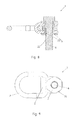
- FIG. 1 shows a stop device 1 according to the invention.
- the stop device 1 has a hanger body 2, an eyelet 3, a filler 4 and bearing bushes 5.
- the connecting device itself is penetrated in the region of the hanger body 2 by a bolt 6 and can be coupled with this bolt 6 at fastening points, not shown here, for example, on containers or the like.
- FIG. 2 shows the stop device 1 according to the invention in a side view
- the hanger body 2 is formed by a U-shape 7.
- the U-shape 7 has a valley area 8 and two legs 9 extending from the valley area 8. Between the legs 9 of the filler 4 is arranged.
- the legs 9 each have a bearing bush 5 with its collar 10 visible arranged.
- the upper portion of the bearing bush 5 is positively against the bolt head 11 and the lower collar 10 by positive engagement with a stop point not shown here.
- the eyelet 3 is arranged in a storage area 12, which is formed between the valley area 8 of the hanger body 2 and a bearing side 13 of the filling body 4.
- a clamping means 14 in the form of a compression spring is further arranged.
- FIG. 3 shows the stop device 1 according to the invention in a plan view, in which case the section line A is shown.
- FIG. 4 a cross section through the stop device 1 according to the invention along the section line A is made FIG. 3 ,
- the bushings 5 are in the illustration according to FIG. 4 arranged in the bracket body and the filler so that they come against each other at a contact point 16 for positive engagement.
- Both the hanger body 2 and the filling body 4 are rotatably mounted in the sequence about an axis of rotation 17, wherein the storage is done by the bearing bush 5 itself.
- the eyelet 3 comes in the storage area 12 of the hanger body 2 to the plant. This is done by a force applied by the tensioning means 14 on the eyelet 3 force 18.
- the diameter D of the bolt 6 is shown.
- FIG. 5 shows a sectional view along the section line B from FIG. 4 ,
- the stop device 1 is shown in a sectional view such that two clamping means 14 are arranged in blind holes 19.
- the eyelet 3 is pivotally arranged about the pivot axis 20, wherein between the pivot axis 20 and the rotation axis 17 of the hanger body 2, a distance a is formed.
- the two spring-elastic clamping means 14 have a distance b to each other. The distance b is approximately equal to each part along a central axis M of the connecting device according to the invention. A tilting of the eyelet 3 is thus largely avoided by an equal force F by the resilient tensioning means 14.
- FIG. 6 shows a same cross section through the stop device 1 according to the invention along the section line A from FIG. 3 , The difference to FIG. 4 is that between the two bushings 5, a spring washer 21 is incorporated. The spring washer 21 engages in an external thread 22 of the bolt. 6
- FIG. 7 shows an alternative embodiment to FIG. 4 with the difference that the two bushings 5 are pressed together in the contact region 16.
- FIG. 8 shows an analogous cross-sectional view through a connecting device according to the invention according to the section line A from FIG. 3 ,
- FIG. 9 shows a view of FIG. 8 from underneath. It can be seen here that an external hexagon 24 is formed on the lower bearing bush 5 with internal thread 23. Here can be arranged on a non-illustrated open-end wrench between the hanger body 2 and the mounting location not shown here, a backup of the bolt 6 done so that an accidental release of the connection device is not possible.
- FIG. 10 shows a further embodiment analogous to FIG. 4 , wherein on the bearing bushes 5, an outer circumferential shoulder 25 is formed, which rests in an inner peripheral groove 26 of the packing 4. The heel thus comes between a flank 27 on the filler 4 and a flank 28 on the hanger body 2 to the plant, so that slipping out of the bearing bush 5 from the hanger body 2 by a positional fixation is not possible.
- the system is manufactured by the spring force F, which is produced by the tensioning means 14.
Landscapes
- Engineering & Computer Science (AREA)
- Mechanical Engineering (AREA)
- Pivots And Pivotal Connections (AREA)
- Connection Of Plates (AREA)
Abstract
Description
Die vorliegende Erfindung betrifft eine Anschlussvorrichtung zum Anschließen von Anschlagmitteln und/oder Verzurrmitteln gemäß den Merkmalen im Oberbegriff von Patentanspruch 1.The present invention relates to a connecting device for connecting stop means and / or lashing means according to the features in the preamble of
Verzurrpunkte zum Koppeln mit Anschlagmitteln und/oder Verzurrmitteln, insbesondere an Paletten, Containern oder anzuhebenden Rahmen sind aus dem Stand der Technik bekannt. Beispielsweise ist aus der
Derart bekannte, flache Verzurrpunkte bieten die Vorteile, dass sie eine hohe Sicherheit gegen Bruch in allen Belastungsrichtungen, bei gleichzeitig sehr flacher Bauform aufweisen. Sie sind um 360 Grad drehbar und die Öse ist um 180 Grad schwenkbar.Such known, flat lashing points have the advantages that they have a high level of security against breakage in all directions of load, at the same time very flat design. They can be rotated 360 degrees and the eyelet can be swiveled through 180 degrees.
Die aus dem Stand der Technik bekannten flachen Verzurrpunkte werden derart hergestellt, dass eine Hülse in einem Bügelkörper durch Umformung des Bügelkörpers eingeschlossen und schwenkbar gelagert wird. Anschließen werden die Verzurrpunkte mit einer Schraube an ihrem zu befestigenden Anschlagpunkt gekoppelt.The known from the prior art flat lashing points are made such that a sleeve is enclosed in a hanger body by forming the hanger body and pivotally mounted. The lashing points are then coupled with a screw at their attachment point to be fastened.
Nachteilig bei den aus dem Stand der Technik bekannten flachen Zurrpunkten ist, dass mitunter die einzelnen Bauteilkomponenten nicht separat voneinander durch verschiedene Härtebehandlungsverfaliren gehärtet werden können, da sie nach dem Zusammenbau eine Einheit ergeben.A disadvantage of the flat lashing points known from the prior art is that sometimes the individual component components can not be hardened separately from one another by different hardness treatment methods since they result in one unit after assembly.
Aufgabe der vorliegenden Erfindung ist es daher ausgehend vom Stand der Technik eine Anschlussvorrichtung in ihrem Gewicht und ihrer Härte zu optimieren und gleichzeitig wartungsfreundlich und leicht in der Montage zu gestalten.Object of the present invention is therefore starting from the prior art to optimize a connection device in their weight and hardness and at the same time to make maintenance friendly and easy to install.
Die zuvor genannte Aufgabe wird mit den Merkmalen von Patentanspruch 1 gelöst.The aforementioned object is achieved with the features of
Vorteilhafte Weiterbildungen sind Gegenstand der abhängigen Patentansprüche.Advantageous developments are the subject of the dependent claims.
Die erfindungsgemäße Anschlussvorrichtung zum Anschließen von Anschlagmitteln und/oder Verzurrmitteln weist einen Bügelkörper und eine Öse auf. Die Öse ist an dem Bügelkörper um eine Schwenkachse schwenkbar gelagert und der Bügelkörper ist mit einem Bolzen an einem Befestigungspunkt um eine Drehachse drehbar koppelbar. In den Bügelkörper sind zwei Lagerbuchsen eingesetzt, über die der Bügelkörper drehbar um die Drehachse gelagert ist. Die Schwenkachse der Öse und die Drehachse des Bügelkörpers sind in einem Winkel zueinander angeordnet, der Vorzugsweise 90 Grad beträgt. Die Drehachse und die Schwenkachse sind zueinander in einem Abstand angeordnet.The connecting device according to the invention for connecting stop means and / or lashing means has a hanger body and an eyelet. The eyelet is pivotally mounted on the bracket body about a pivot axis and the bracket body is rotatably coupled to a bolt at an attachment point about an axis of rotation. In the hanger body two bushings are used, via which the hanger body is rotatably mounted about the axis of rotation. The pivot axis of the eyelet and the axis of rotation of the hanger body are arranged at an angle to each other, which is preferably 90 degrees. The axis of rotation and the pivot axis are arranged at a distance from one another.
Erfindungsgemäß ist der Bügelkörper in seinem Querschnitt U-förmig konfiguriert. In dem Bügelkörper selber ist ein Füllkörper angeordnet, wobei zwischen dem Füllkörper und dem im Talbereich des U-förmig konfigurierten Bügelkörpers ein Lagerbereich für die Öse ausgebildet ist. Der Füllkörper ist erfindungsgemäß entnehmbar in dem Bügelkörper angeordnet, so dass durch Entnahme des Füllkörpers die Öse aus dem Bügelkörper ebenfalls entnehmbar ist.According to the invention, the hanger body is U-shaped in its cross-section. In the bracket body itself, a packing is arranged, wherein between the filling body and the in the valley region of the U-shaped configured hanger body a storage area for the eyelet is formed. The filler is according to the invention removably arranged in the hanger body, so that by removing the filler body, the eyelet from the hanger body is also removed.
Der erfindungsgemäße Vorteil ergibt sich dadurch, dass alle Bauteilkomponenten einzeln hergestellt und derart bearbeitet werden können, dass sie beiastungstechnisch optimal ausgelegt sind. Konkret bedeutet dies, dass sowohl der Bügelkörper als auch der Füllkörper und die Öse einzeln hergestellt und auch einzeln durch beispielsweise eine Wärmebehandlung gehärtet sein können und somit jeweils eine spezifische Härte, Reiß- und Zugfestigkeit aufweisen, die nicht durch einzelne Herstellungsschritte des zusammengesetzten Bauteils beeinflusst sind.The advantage according to the invention results from the fact that all component components can be manufactured individually and processed in such a way that they are optimally designed with regard to interlocking technology. Specifically, this means that both the stirrup body and the filler body and the eyelet can be manufactured individually and also cured individually by, for example, a heat treatment and thus each have a specific hardness, tear and tensile strength, which are not influenced by individual manufacturing steps of the assembled component ,
Ebenfalls sind die Herstellung und auch die Produktion der einzelnen Komponenten besonders unter technologischen Aspekten einfach durchführbar und bietet somit enorme Kosteneinsparungspotentiale bei der Herstellung des erfindungsgemäßen Anschlagpunktes,Likewise, the production and also the production of the individual components are easy to carry out, especially under technological aspects, and thus offers enormous cost savings potential in the production of the attachment point according to the invention,
Die erfindungsgemäßen Anschlussvorrichtungen können auch in Form von Verzurrpunkten auf Mulden von Lkw-Pritschen, Schiffs-Ladeflächen oder ähnlichem eingesetzt werden.The connecting devices according to the invention can also be used in the form of lashing points on troughs of truck beds, ship loading areas or the like.
Weiterhin bevorzugt ist zwischen dem Füllkörper und der Öse ein federelastisches Spannmittel angeordnet, mit dem die schwenkbare Öse in einer jeweiligen Position arretierbar ist. Bei dem federelastischen Spannmittel handelt es sich beispielsweise um eine Feder, bevorzugt eine Schraubenfeder. Das federelastische Spannmittel ist zwischen dem Füllkörper und der Öse derart angeordnet, dass eine Druckkraft von dem Füllkörper über das Spannmittel auf die Öse ausgeübt wird. Die Öse wird folglich im Talbereich des U-förmig konfigurierten Füllkörpers von innen an den Talbereich und/oder an den Lagerbereich angedrückt. In der Folge entsteht eine Reibkraft zwischen der Öse und dem Lagerbereich, so dass die Öse in einer jeweils geschwenkten Position verbleibt. Dies bietet im Rahmen der Erfindung die Möglichkeit, dass die Öse für den anwendenden Monteur in einer Arbeitsposition schwenkbar ist und dann ein Anschlagmittel, beispielsweise eine Kette, einhängbar ist.Further preferably, a resilient tensioning means is arranged between the filling body and the eyelet, with which the pivotable eyelet can be locked in a respective position. The spring-elastic clamping means is, for example, a spring, preferably a helical spring. The elastic tensioning means is arranged between the filling body and the eyelet in such a way that a pressure force is exerted by the filling body on the eyelet via the tensioning means. The eyelet is thus pressed in the valley of the U-shaped configured packing from the inside to the valley area and / or to the storage area. As a result, a frictional force between the eyelet and the bearing area, so that the eyelet in a pivoted each Position remains. This provides in the context of the invention, the possibility that the eyelet for the user mechanic is pivotable in a working position and then a stop means, such as a chain, can be suspended.
Wird der Anschlagpunkt nicht verwendet, ist die Öse abklappbar, so dass er als flacher Anschlagpunkt keinen Lagerraum oder aber Arbeitsraum einnimmt. Das federelastische Spannmittel ist bevorzugt in einer Sacklochbohrung in dem Füllkörper angeordnet. Hierdurch ergibt sich auch wiederum der Vorteil, dass der Zusammenbau der erfindungsgemäßen Anschlussvorrichtung sich besonders leicht gestaltet. Das federelastische Spannmittel ist dabei im Betrieb einem erhöhten Verschleiß bzw. einer erhöhten Belastung ausgesetzt. Durch das einfache Zerlegen und Zusammensetzen der erfindungsgemäßen Anschlussvorrichtung ist es besonders einfach, das Spannmittel zu tauschen. Ebenfalls kann das Spannmittel im Rahmen der Erfindung an seinen Enden besonders bearbeitet sein. Beispielsweise kann es abgeflacht sein oder aber auch eine Überstülpung in Form einer Hülse oder aber eines Niets aufweisen, so dass wiederum die Verschleißfestigkeit des Spannmittels und auch die Fixierbarkeit der Öse optimiert sind.If the anchor point is not used, the eyelet can be folded down, so that it does not occupy a storage space or working space as a flat attachment point. The resilient tensioning means is preferably arranged in a blind hole in the filling body. This in turn also results in the advantage that the assembly of the connecting device according to the invention is particularly easy. The spring-elastic clamping device is exposed during operation to increased wear or increased stress. Due to the simple disassembly and assembly of the connecting device according to the invention, it is particularly easy to replace the clamping device. Also, the clamping means may be specially processed in the invention at its ends. For example, it may be flattened or may also have a protuberance in the form of a sleeve or a rivet, so that in turn the wear resistance of the clamping device and also the fixability of the eyelet are optimized.
In einer besonders bevorzugten Ausführungsform sind zwei federelastische Spannmittel zwischen dem Füllkörper und der Öse angeordnet. Bevorzugt sind die zwei federelastischen Spannmittel derart angeordnet, dass sie jeweils in einem 90 Grad Winkel zu der Schwenkachse der Öse parallel mit einem Abstand nebeneinander angeordnet sind. Dies bietet insbesondere den Vorteil, dass die Öse in dem Lagerbereich nicht verkanten kann bzw. nicht schlackert. Sie wird also besonders präzise immer in der jeweiligen Arbeitsposition schwenkbar gehalten.In a particularly preferred embodiment, two resilient clamping means between the filler and the eyelet are arranged. Preferably, the two resilient clamping means are arranged such that they are each arranged at a 90 degree angle to the pivot axis of the eyelet parallel to a distance next to each other. This offers in particular the advantage that the eyelet can not tilt in the storage area or not schlackert. It is therefore always very precisely kept pivotable in the respective working position.
Ein weiterer Vorteil ist, dass sich der Füllkörper durch die zwei Spannmittel nicht innerhalb des Bügelkörpers verschieben bzw. verdrehen kann.Another advantage is that the filler can not move or twist within the hanger body by the two clamping means.
Der Füllkörper ist besonders vorteilig derart dimensioniert, dass er an den Schenkeln der U-Form des Bügelkörpers zumindest abschnittsweise flächig anliegt. Durch die formschlüssige Anlage gibt der Füllkörper dem Bügelkörper eine erhöhte Steifigkeit und einen passgenauen Sitz, insbesondere mit Blick auf die Befestigung mit dem Bolzen und auch auf den Lagerbereich. Im Rahmen der Erfindung ist der Füllkörper dabei in seiner Dicke, dies bedeutet der Bereich zwischen den beiden Schenkeln des U-förmig konfigurierten Bügelkörpers, immer mindestens minimal größer ausgebildet, als der Durchmesser der Öse im Lagerbereich.The filler is particularly advantageously dimensioned such that it rests on the legs of the U-shape of the hanger body at least partially flat. Due to the positive fitment of the filler gives the hanger body an increased rigidity and a snug fit, especially with regard to the attachment to the bolt and also to the storage area. In the context of the invention, the filler body is in its thickness, this means the area between the two legs of the U-shaped configured hanger body, always formed at least minimally larger than the diameter of the eyelet in the storage area.
Bevorzugt ist der Füllkörper von den Lagerbuchsen durchgriffen und die Lagerbuchsen und die zwei Spannmittel halten den Füllkörper in seiner Relativposition zu dem Befestigungskörper fixiert. Hierdurch ist durch einen Formschluss ein sicherer und fester Halt der gesamten Anschlussvorrichtung gegeben. Es muss also nicht durch ein Eintreiben von Öse oder Füllkörper mit aufwendigen mechanischen Koppelungsverfahren oder aber durch ein weiteres Fügeverfahren, beispielsweise Schweißen oder aber auch Kleben oder aber ein Umformverfahren, der Zusammenbau des erfindungsgemäßen Anschlussvorrichtung hergestellt werden. Durch besonders leichtes Zusammensetzen bzw. umgekehrt durch einfaches Zerlegen, ist die erfindungsgemäße Anschlussvorrichtung somit besonders wartungs- und bedienfreundlich komplettierbar.Preferably, the filler is penetrated by the bearing bushes and the bearing bushes and the two clamping means keep the filler fixed in its relative position to the mounting body. As a result, a positive and firm hold of the entire connection device is given by a positive connection. Thus, it is not necessary to produce the assembly of the connecting device according to the invention by driving in eyelet or packing with complicated mechanical coupling methods or else by a further joining method, for example welding or else gluing or else a shaping method. By particularly easy assembly and vice versa by simple disassembly, the connection device according to the invention is thus completed particularly maintenance and easy to use.
Hierdurch ergibt sich auch der Vorteil, dass der Füllkörper durch Entnahme der Lagerbuchse aus dem Befestigungskörper entnehmbar ist. Im Falle eines Verschleißes oder aber beispielsweise einer Verschleißprüfung des Bügelkörpers ist es somit möglich, durch Entnahme des Füllkörpers den Bügelkörper überprüfen zu lassen,This also results in the advantage that the filler can be removed by removing the bearing bush from the mounting body. In the case of wear or, for example, a wear test of the hanger body, it is thus possible to check by removing the filler body the hanger body,
Durch die Entnahme des Füllkörpers aus dem Bügelkörper ist es somit auch möglich, die Öse aus dem Bügelkörper zu entnehmen. Im Falle einer beschädigten Öse oder aber einer gerissenen Öse oder aber auch einer verschließenen Öse ist es somit möglich, durch Sachkundige die Öse einzeln zu wechseln. Es ist somit besonders unter wartungsfreundlichen Aspekten möglich, die erfindungsgemäßen Anschlussvorrichtungen durch Generalüberholungen zu erneuern. Es müssen somit nicht alle aufwendigen Verfahrensschritte zum Herstellen einer kompletten Anschlussvorrichtung wiederholt werden, sondern beispielsweise wird nur durch Auswechseln einer verschlissenen Öse der Einsatz der erfindungsgemäßen Anschlussvorrichtung wiederum generiert.By removing the filling body from the hanger body, it is thus also possible to remove the eyelet from the hanger body. In the case of a damaged eye or a torn eyelet or even a closed eyelet, it is thus possible to change the eyelet individually by experts. It is thus possible, especially under maintenance-friendly aspects, to renew the connecting devices according to the invention by general overhauls. It does not have to be expensive Procedural steps for producing a complete connection device are repeated, but for example, the use of the connection device according to the invention is in turn generated only by replacing a worn eye.
In einer weiteren bevorzugten Ausführungsvariante weist der Füllkörper an seiner zu der Öse orientierten Seite eine Lagerseite auf. Hierunter ist beispielsweise eine ebenfalls U-förmige Konfiguration zu verstehen. Das heißt, die Lagerseite ist derart ausgebildet, dass sie einen Radius aufweist, der im Wesentlichen dem Radius der Öse im Lagerbereich entspricht. Im Falle der Handhabung der Verzurrpunkte ist somit auch unter Last sichergestellt, dass die Öse im Lagerbereich, insbesondere an der Lagerseite des Füllkörpers immer schwenkbar gelagert bleibt.In a further preferred embodiment variant, the filler has a bearing side on its side oriented toward the eyelet. This is, for example, a likewise U-shaped configuration to understand. That is, the bearing side is formed such that it has a radius which substantially corresponds to the radius of the eyelet in the storage area. In the case of handling the lashing points is thus ensured even under load that the eyelet always remains pivotally mounted in the storage area, in particular on the bearing side of the packing.
In einer weiteren vorteilhaften Ausführungsvariante ist zwischen den Lagerbuchsen eine Federscheibe eingegliedert. Die Federscheibe greift bei Einschrauben eines Bolzens zur Befestigung der Aufnahmevorrichtung an beispielsweise einem Befestigungsort an einem Container o. ä. in das Außengewinde des Bolzens ein. Hierdurch wird sichergestellt, dass die Lagerschalen nicht aus dem Bolzen herausfallen können. Ebenfalls übt die Federscheibe immer eine derartige Kraft auf den Bolzen aus, so dass ein ungewolltes Lösen der Anschlussvorrichtung vermieden ist.In a further advantageous embodiment, a spring washer is incorporated between the bearing bushes. The spring washer engages when screwing a bolt for fastening the receiving device to, for example, a mounting location on a container o. Ä. In the external thread of the bolt. This ensures that the bearing shells can not fall out of the bolt. Also, the spring washer always exerts such a force on the bolt, so that an unwanted loosening of the connection device is avoided.
In einer anderen Ausführungsvariante werden die Lagerbuchsen in dem Bügelkörper miteinander verpresst. Sie durchgreifen somit den in dem Bügelkörper angeordneten Füllkörper und werden miteinander verpresst, so dass keines der Bauteile sich lösen kann. Gleichzeitig werden die beiden Lagerbuchsen derart miteinander verpresst, dass der Bügelkörper und auch der Füllkörper um die Lagerbuchsen rotieren können.In another embodiment, the bearing bushes are pressed together in the bracket body. They thus pass through the arranged in the ironing body filler and are pressed together so that none of the components can be solved. At the same time, the two bearing bushes are pressed together in such a way that the hanger body and also the filler body can rotate about the bearing bushes.
In einer weiteren bevorzugten Ausführungsvariante ist zumindestens eine Lagerbuchse mit einem Innengewinde ausgebildet. Hierdurch ergibt sich die Möglichkeit, dass in das Innengewinde das Außengewinde des Bolzens einschraubbar ist. Nach Montage der Anschlussvorrichtung ist es somit möglich, über ein Gegenziehen der Lagerbuchse mit dem Innengewinde diese zusätzlich zu sichern. Die Lagerbuchse mit dem innengewinde übernimmt somit eine Sicherungsfunktion des Bolzens bei gleichzeitiger Lagerungsfunktion für den Bügelkörper und den Füllkörper. Besonders bevorzugt ist die Lagerbuchse mit dem Innengewinde derart ausgebildet, dass sie über formschlüssigen Werkzeugeingriff, beispielsweise über einen Außensechskant, justierbar ist.In a further preferred embodiment, at least one bearing bush is formed with an internal thread. This results in the possibility that in the internal thread, the external thread of the bolt is screwed. After mounting the connection device, it is thus It is possible to additionally secure it by countering the bearing bush with the internal thread. The bearing bush with the internal thread thus assumes a safety function of the bolt with simultaneous storage function for the hanger body and the filler. Particularly preferably, the bearing bush with the internal thread is designed such that it is adjustable via positive tool engagement, for example via an external hexagon.
In einer weiteren bevorzugten Ausführungsvariante der vorliegenden Erfindung ist in der Öffnung des Füllkörpers eine umlaufende Nut ausgebildet. Die Nut selbst kann an ihren Flanken durch den Füllkörper oder aber auf der einen Seite durch den Füllkörper und auf der anderen Seite durch den Bügelkörper begrenzt sein. Weiterhin weist bevorzugt mindestens eine Lagerbuchse einen außenliegenden Absatz auf. Bei Zusammenbau der erfindungsgemäßen Anschlussvorrichtung kommt dieser Absatz zumindest abschnittsweise zum Eingriff mit der zuvor beschriebenen Nut. Der zumindest abschnittsweise Eingriff ergibt sich aus der Wirkung des federelastischen Spannmittels, Es erfolgt damit ein Verkanten der Lagerbuchsen in dem Bügelkörper, so dass diese nur durch händische oder aber mechanische Einwirkung aus dem Bügelkörper entnommen werden können und mithin nicht bei der Montage, Lagerung oder durch den Transport aus dem Bügelkörper herausfallen.In a further preferred embodiment of the present invention, a circumferential groove is formed in the opening of the filling body. The groove itself may be bounded on its flanks by the filler body or else on one side by the filler body and on the other side by the ironing body. Furthermore, at least one bearing bush preferably has an outer shoulder. When assembling the connecting device according to the invention this paragraph is at least partially engaged with the previously described groove. The at least partially engagement results from the action of the spring-elastic clamping means, It is thus a tilting of the bearing bushes in the hanger body, so that they can be removed only by manual or mechanical action from the hanger body and therefore not during assembly, storage or by the transport fall out of the hanger body.
Ebenfalls besonders vorteilig kann zusätzlich ein Einsatz in dem U-förmigen Talbereich des Bügelkörpers vorhanden sein. Dieser Einsatz kann beispielsweise aus einem Einsatz in Form einer Teflonlagerbuchse oder aber einer anderweitigen metallischen oder kunststoffartigen Lagerbuchse ausgebildet sein. Auch hier ergibt sich insbesondere der Vorteil, dass auch unter Last die Öse grundsätzlich schwenkbar gelagert ist.Also particularly advantageous may additionally be an insert in the U-shaped valley region of the hanger body. This insert can be formed for example from an insert in the form of a Teflon bearing bush or other metal or plastic-like bearing bush. Again, there is the particular advantage that even under load, the eye is basically pivotally mounted.
In einer bevorzugten Ausführungsvariante der vorliegenden Erfindung entspricht der Abstand (a) zwischen der Drehachse und der Schwenkachse vorzugsweise dem 0,25 bis 4-fachen des Durchmessers des zur Befestigung der Anschlussvorrichtung vorgesehenen Bolzens. Insbesondere entspricht der Abstand (a) dem 0,5 bis 2,5-fachen und besonders bevorzugt dem 1 bis 2-fachen. Gerade unter produktionstechnischen Aspekten ergibt sich somit ein optimaler Abstand zwischen Schwenkbarkeit und Bedienbarkeit der erfindungsgemäßen Anschlussvorrichtung unter Ausnutzung eines optimalen durch den Abstand (a) hergestellten Hebelarmverhältnisses.In a preferred embodiment of the present invention, the distance (a) between the axis of rotation and the pivot axis preferably corresponds to 0.25 to 4 times the diameter of the bolt provided for fastening the connecting device. In particular, corresponds to the Distance (a) 0.5 to 2.5 times and more preferably 1 to 2 times. Especially under aspects of production technology, this results in an optimal distance between pivoting and operability of the connecting device according to the invention by utilizing an optimal lever arm ratio produced by the distance (a).
Weiterhin entspricht der Abstand (b) dem 0,5 bis 2,5-fachen, insbesondere dem 1 bis 2-fachen des Durchmessers des zur Befestigung des erfindungsgemäßen Anschlagpunktes benötigten Bolzens. Hierdurch ergibt sich immer eine optimale Abstandsproportionierung der zwei federelastischen Spannmittel unter Berücksichtigung des jeweils eingesetzten Bolzens.Furthermore, the distance (b) corresponds to 0.5 to 2.5 times, in particular 1 to 2 times the diameter of the bolt required for fastening the attachment point according to the invention. This always results in an optimal distance proportioning of the two resilient clamping means, taking into account the bolt used in each case.
Weitere Vorteile, Merkmale, Aspekte und Eigenschaften der vorliegenden Erfindung ergeben sich aus der folgenden Beschreibung. Bevorzugte Ausführungsvarianten sind in den Figuren dargestellt. Diese dienen dem einfachen Verständnis der vorliegenden Erfindung. Es zeigen:
Figur 1- einen erfindungsgemäßen Anschlagpunkt in einer perspektivischen Ansicht;
Figur 2- den erfindungsgemäßen Anschlagpunkt in einer Seitenansicht;
Figur 3- den erfindungsgemäßen Anschlagpunkt in einer Draufsicht;
- Figur 4
- den erfindungsgemäßen Anschlagpunkt in der Schnittansicht A;
Figur 5- den erfindungsgemäßen Anschlagpunkt in der Schnittansicht B,
Figur 6- den erfindungsgemäßen Anschlagpunkt in einer Schnittansicht mit einer Nut und Absatz,
Figur 7- den erfindungsgemäßen Anschlagpunkt in der Schnittansicht A,
Figur 8- den erfindungsgemäßen Anschlagpunkt mit Lagerbuchse und Innengewinde,
Figur 9- den erfindungsgemäßen Anschlagpunkt in einer Ansicht von unten,
Figur 10- den erfindungsgemäßen Anschlagpunkt mit Nut und Rezess.
- FIG. 1
- an attachment point according to the invention in a perspective view;
- FIG. 2
- the attachment point according to the invention in a side view;
- FIG. 3
- the stopper according to the invention in a plan view;
- FIG. 4
- the attachment point according to the invention in the sectional view A;
- FIG. 5
- the attachment point according to the invention in the sectional view B,
- FIG. 6
- the attachment point according to the invention in a sectional view with a groove and paragraph,
- FIG. 7
- the attachment point according to the invention in the sectional view A,
- FIG. 8
- the attachment point according to the invention with bearing bush and internal thread,
- FIG. 9
- the attachment point according to the invention in a view from below,
- FIG. 10
- the attachment point according to the invention with groove and recess.
In den Figuren werden für gleiche oder ähnliche Bauteile dieselben Bezugszeichen verwendet, auch wenn eine wiederholte Beschreibung aus Vereinfachungsgründen entfällt.In the figures, the same reference numerals are used for the same or similar components, even if a repeated description is omitted for reasons of simplicity.
In
Auch
Die auf die Bildebene bezogene untere Lagerbuchse 5 weist zusätzlich ein Innengewinde 23 auf, das in das Außengewinde 22 des Bolzens 6 eingreift.The
- 1 -1 -
- Anschlagvorrichtungstop device
- 2 -2 -
- Bügelkörperhanger body
- 3-3
- Öseeyelet
- 4-4
- Füllkörperpacking
- 5 -5 -
- Lagerbuchsebearing bush
- 6-6
- Bolzenbolt
- 7 -7 -
- U-FormU-shape
- 8 -8th -
- Talbereichvalley
- 9-9-
- Schenkelleg
- 10-10-
- Kragencollar
- 11 -11 -
- Bolzenkopfbolt head
- 12-12-
- Lagerbereichstorage area
- 13-13-
- Lagerseitebearing side
- 14-14-
- Spannmittelclamping means
- 15-15
- hülsenförmiger Abschnitt zu 5,sleeve-shaped section to 5,
- 16 -16 -
- Koppelbereichcoupling region
- 17-17-
- Drehachseaxis of rotation
- 18-18-
- Kraftforce
- 19-19-
- SacklochbohrungBlind hole
- 20 -20 -
- Schwenkachseswivel axis
- 21 -21 -
- Federscheibespring washer
- 22 -22 -
- Außengewindeexternal thread
- 23-23-
- Innengewindeinner thread
- 24 -24 -
- AußensechskantExternal hexagon
- 25-25
- Absatzparagraph
- 26-26-
- Nutgroove
- 27-27-
- Flankeflank
- 28 -28 -
- Flankeflank
- a -a -
- Abstanddistance
- b -b -
- Abstanddistance
- A -A -
- Schnittlinieintersection
- M -M -
- Mittelachsecentral axis
- F -F -
- Krafteinwirkungforce
- D -D -
- Durchmesserdiameter
Claims (13)
Applications Claiming Priority (1)
| Application Number | Priority Date | Filing Date | Title |
|---|---|---|---|
| DE201010032571 DE102010032571A1 (en) | 2010-07-28 | 2010-07-28 | Flat lashing point |
Publications (2)
| Publication Number | Publication Date |
|---|---|
| EP2412660A1 true EP2412660A1 (en) | 2012-02-01 |
| EP2412660B1 EP2412660B1 (en) | 2013-11-20 |
Family
ID=44735783
Family Applications (1)
| Application Number | Title | Priority Date | Filing Date |
|---|---|---|---|
| EP11169269.5A Active EP2412660B1 (en) | 2010-07-28 | 2011-06-09 | Flat tie down point |
Country Status (2)
| Country | Link |
|---|---|
| EP (1) | EP2412660B1 (en) |
| DE (1) | DE102010032571A1 (en) |
Cited By (5)
| Publication number | Priority date | Publication date | Assignee | Title |
|---|---|---|---|---|
| CN103466433A (en) * | 2013-09-09 | 2013-12-25 | 中达电机股份有限公司 | Universal lifting bar |
| LU92242B1 (en) * | 2013-07-08 | 2015-01-09 | Intelprop Sa | Revolving lifting point |
| LU92243B1 (en) * | 2013-07-08 | 2015-01-09 | Intelprop Sa | Lifting ring |
| WO2015169673A1 (en) * | 2014-05-09 | 2015-11-12 | Rud Ketten Rieger & Dietz Gmbh U. Co. Kg | Ring element having a divided base for a lashing or attachment means |
| WO2023149177A1 (en) * | 2022-02-03 | 2023-08-10 | 株式会社キトー | Hanging fitting |
Citations (7)
| Publication number | Priority date | Publication date | Assignee | Title |
|---|---|---|---|---|
| DE8601343U1 (en) * | 1986-01-21 | 1986-04-03 | Thiele GmbH & Co. KG, 58640 Iserlohn | Rotatable transport ring |
| US6068310A (en) * | 1998-09-04 | 2000-05-30 | Jergens, Inc. | Hoist ring |
| DE10013845A1 (en) | 2000-03-15 | 2001-09-27 | Rud Ketten Rieger & Dietz | Connecting device |
| DE20121121U1 (en) * | 2001-12-21 | 2002-04-25 | Rud Ketten Rieger & Dietz | Connection device for connecting sling or lashing equipment |
| AT412269B (en) * | 2003-08-13 | 2004-12-27 | Pewag Austria Gmbh | CONNECTING DEVICE AND FIXING ELEMENT |
| EP1840070A2 (en) * | 2006-03-29 | 2007-10-03 | PEWAG AUSTRIA GmbH | Connecting device |
| EP1961689A1 (en) * | 2007-02-22 | 2008-08-27 | Stamperia Carcano Giuseppe S.p.A. | Fastening device, component, kit and method adapted for manufacturing said device |
Family Cites Families (3)
| Publication number | Priority date | Publication date | Assignee | Title |
|---|---|---|---|---|
| US4431352A (en) * | 1981-09-28 | 1984-02-14 | Andrews Gary E | Fastening device |
| DE3822690C1 (en) * | 1988-07-05 | 1990-03-08 | Thiele, August, 5860 Iserlohn, De | Stop device for hoisting, hauling or lashing means |
| DE10164598B4 (en) * | 2001-12-21 | 2006-12-14 | Rud-Kettenfabrik Rieger & Dietz Gmbh U. Co. | Connecting device for connecting stop or lashing devices |
-
2010
- 2010-07-28 DE DE201010032571 patent/DE102010032571A1/en active Pending
-
2011
- 2011-06-09 EP EP11169269.5A patent/EP2412660B1/en active Active
Patent Citations (7)
| Publication number | Priority date | Publication date | Assignee | Title |
|---|---|---|---|---|
| DE8601343U1 (en) * | 1986-01-21 | 1986-04-03 | Thiele GmbH & Co. KG, 58640 Iserlohn | Rotatable transport ring |
| US6068310A (en) * | 1998-09-04 | 2000-05-30 | Jergens, Inc. | Hoist ring |
| DE10013845A1 (en) | 2000-03-15 | 2001-09-27 | Rud Ketten Rieger & Dietz | Connecting device |
| DE20121121U1 (en) * | 2001-12-21 | 2002-04-25 | Rud Ketten Rieger & Dietz | Connection device for connecting sling or lashing equipment |
| AT412269B (en) * | 2003-08-13 | 2004-12-27 | Pewag Austria Gmbh | CONNECTING DEVICE AND FIXING ELEMENT |
| EP1840070A2 (en) * | 2006-03-29 | 2007-10-03 | PEWAG AUSTRIA GmbH | Connecting device |
| EP1961689A1 (en) * | 2007-02-22 | 2008-08-27 | Stamperia Carcano Giuseppe S.p.A. | Fastening device, component, kit and method adapted for manufacturing said device |
Cited By (8)
| Publication number | Priority date | Publication date | Assignee | Title |
|---|---|---|---|---|
| LU92242B1 (en) * | 2013-07-08 | 2015-01-09 | Intelprop Sa | Revolving lifting point |
| LU92243B1 (en) * | 2013-07-08 | 2015-01-09 | Intelprop Sa | Lifting ring |
| WO2015004124A1 (en) * | 2013-07-08 | 2015-01-15 | Intelprop S.A. | Lifting bolt |
| WO2015004126A1 (en) * | 2013-07-08 | 2015-01-15 | Intelprop S.A. | Rotating lifting bolt |
| CN103466433A (en) * | 2013-09-09 | 2013-12-25 | 中达电机股份有限公司 | Universal lifting bar |
| WO2015169673A1 (en) * | 2014-05-09 | 2015-11-12 | Rud Ketten Rieger & Dietz Gmbh U. Co. Kg | Ring element having a divided base for a lashing or attachment means |
| US10131523B2 (en) | 2014-05-09 | 2018-11-20 | Rud Ketten Rieger & Dietz Gmbh U. Co. K.G. | Ring element having a divided base for a lashing or attachment means |
| WO2023149177A1 (en) * | 2022-02-03 | 2023-08-10 | 株式会社キトー | Hanging fitting |
Also Published As
| Publication number | Publication date |
|---|---|
| DE102010032571A1 (en) | 2012-02-02 |
| EP2412660B1 (en) | 2013-11-20 |
Similar Documents
| Publication | Publication Date | Title |
|---|---|---|
| EP0803332B1 (en) | Device for the pressing out of the pivot pin of a suspension joint and/or of a track rod | |
| EP2412660B1 (en) | Flat tie down point | |
| WO2018073098A1 (en) | Tensioning device for ropes and chains, comprising a lead screw and ratchet unit | |
| EP2844601B1 (en) | Ring bolt with sliding disc | |
| EP3167205A1 (en) | Block lock with a twist lock | |
| WO2003072427A2 (en) | Container lashing device | |
| DE102012110208B4 (en) | Actuation unit for a vehicle seat | |
| DE102004020000B4 (en) | Suspension element | |
| WO2015144659A1 (en) | Device for lashing containers | |
| DE602005001503T2 (en) | Swing device for scissors | |
| DE202006014999U1 (en) | Spring compressor for compressing coil spring, has compressor plate with pocket on its outer side, where pocket extends to circumferential side of opening, and two thrust bearing bodies provided at pressure piece for engaging in pocket | |
| EP1580073B1 (en) | Locking device for fixing containers on vehicles | |
| DE19748117C2 (en) | ball pin | |
| DE102015115040A1 (en) | trampoline | |
| EP3722244B1 (en) | Vertebral screw | |
| DE112006002662B4 (en) | Leaf spring with convex top and bottom | |
| EP0645216B1 (en) | Spring compressor for MacPherson strut suspension | |
| DE102005004943A1 (en) | Protection device for protecting a lashing device, has lashing device with oblong lashing unit and clamping bolt that includes connection part and threaded shaft, on which clamping unit and closure unit are removably attached | |
| DE10236031C1 (en) | Rising butt hinge for door or window has hinge pin sleeves with flanges and lobes end surfaces which mutually engage | |
| DE102010001183B4 (en) | Fastening element for accommodating a wiper arm | |
| DE202008002992U1 (en) | Turnbuckle for lashing loads, especially on vehicles | |
| DE102008012293A1 (en) | Turnbuckle for clamping load on vehicle, has safety device securing spindle against unintentional rotation of spindle in tube and comprising safety lever that is movable relative to tube, spindle and fastening ring | |
| WO2003097429A1 (en) | Dual-linkage assembly | |
| DE3630463C2 (en) | Door stops, in particular for motor vehicle doors | |
| DE102005041473A1 (en) | Vehicle roof antenna includes pivot mechanism with axis inclined with respect to both position of normal use and position when swung down |
Legal Events
| Date | Code | Title | Description |
|---|---|---|---|
| AK | Designated contracting states |
Kind code of ref document: A1 Designated state(s): AL AT BE BG CH CY CZ DE DK EE ES FI FR GB GR HR HU IE IS IT LI LT LU LV MC MK MT NL NO PL PT RO RS SE SI SK SM TR |
|
| AX | Request for extension of the european patent |
Extension state: BA ME |
|
| PUAI | Public reference made under article 153(3) epc to a published international application that has entered the european phase |
Free format text: ORIGINAL CODE: 0009012 |
|
| 17P | Request for examination filed |
Effective date: 20120126 |
|
| RIC1 | Information provided on ipc code assigned before grant |
Ipc: B66C 1/66 20060101AFI20130514BHEP |
|
| GRAP | Despatch of communication of intention to grant a patent |
Free format text: ORIGINAL CODE: EPIDOSNIGR1 |
|
| INTG | Intention to grant announced |
Effective date: 20130826 |
|
| GRAS | Grant fee paid |
Free format text: ORIGINAL CODE: EPIDOSNIGR3 |
|
| GRAA | (expected) grant |
Free format text: ORIGINAL CODE: 0009210 |
|
| AK | Designated contracting states |
Kind code of ref document: B1 Designated state(s): AL AT BE BG CH CY CZ DE DK EE ES FI FR GB GR HR HU IE IS IT LI LT LU LV MC MK MT NL NO PL PT RO RS SE SI SK SM TR |
|
| REG | Reference to a national code |
Ref country code: GB Ref legal event code: FG4D Free format text: NOT ENGLISH |
|
| REG | Reference to a national code |
Ref country code: CH Ref legal event code: EP |
|
| REG | Reference to a national code |
Ref country code: AT Ref legal event code: REF Ref document number: 641484 Country of ref document: AT Kind code of ref document: T Effective date: 20131215 |
|
| REG | Reference to a national code |
Ref country code: IE Ref legal event code: FG4D Free format text: LANGUAGE OF EP DOCUMENT: GERMAN |
|
| REG | Reference to a national code |
Ref country code: DE Ref legal event code: R096 Ref document number: 502011001669 Country of ref document: DE Effective date: 20140116 |
|
| REG | Reference to a national code |
Ref country code: NL Ref legal event code: VDEP Effective date: 20131120 |
|
| REG | Reference to a national code |
Ref country code: LT Ref legal event code: MG4D |
|
| PG25 | Lapsed in a contracting state [announced via postgrant information from national office to epo] |
Ref country code: SE Free format text: LAPSE BECAUSE OF FAILURE TO SUBMIT A TRANSLATION OF THE DESCRIPTION OR TO PAY THE FEE WITHIN THE PRESCRIBED TIME-LIMIT Effective date: 20131120 Ref country code: IS Free format text: LAPSE BECAUSE OF FAILURE TO SUBMIT A TRANSLATION OF THE DESCRIPTION OR TO PAY THE FEE WITHIN THE PRESCRIBED TIME-LIMIT Effective date: 20140320 Ref country code: NL Free format text: LAPSE BECAUSE OF FAILURE TO SUBMIT A TRANSLATION OF THE DESCRIPTION OR TO PAY THE FEE WITHIN THE PRESCRIBED TIME-LIMIT Effective date: 20131120 Ref country code: LT Free format text: LAPSE BECAUSE OF FAILURE TO SUBMIT A TRANSLATION OF THE DESCRIPTION OR TO PAY THE FEE WITHIN THE PRESCRIBED TIME-LIMIT Effective date: 20131120 Ref country code: FI Free format text: LAPSE BECAUSE OF FAILURE TO SUBMIT A TRANSLATION OF THE DESCRIPTION OR TO PAY THE FEE WITHIN THE PRESCRIBED TIME-LIMIT Effective date: 20131120 Ref country code: HR Free format text: LAPSE BECAUSE OF FAILURE TO SUBMIT A TRANSLATION OF THE DESCRIPTION OR TO PAY THE FEE WITHIN THE PRESCRIBED TIME-LIMIT Effective date: 20131120 Ref country code: NO Free format text: LAPSE BECAUSE OF FAILURE TO SUBMIT A TRANSLATION OF THE DESCRIPTION OR TO PAY THE FEE WITHIN THE PRESCRIBED TIME-LIMIT Effective date: 20140220 |
|
| PG25 | Lapsed in a contracting state [announced via postgrant information from national office to epo] |
Ref country code: LV Free format text: LAPSE BECAUSE OF FAILURE TO SUBMIT A TRANSLATION OF THE DESCRIPTION OR TO PAY THE FEE WITHIN THE PRESCRIBED TIME-LIMIT Effective date: 20131120 Ref country code: ES Free format text: LAPSE BECAUSE OF FAILURE TO SUBMIT A TRANSLATION OF THE DESCRIPTION OR TO PAY THE FEE WITHIN THE PRESCRIBED TIME-LIMIT Effective date: 20131120 Ref country code: RS Free format text: LAPSE BECAUSE OF FAILURE TO SUBMIT A TRANSLATION OF THE DESCRIPTION OR TO PAY THE FEE WITHIN THE PRESCRIBED TIME-LIMIT Effective date: 20131120 |
|
| PG25 | Lapsed in a contracting state [announced via postgrant information from national office to epo] |
Ref country code: PT Free format text: LAPSE BECAUSE OF FAILURE TO SUBMIT A TRANSLATION OF THE DESCRIPTION OR TO PAY THE FEE WITHIN THE PRESCRIBED TIME-LIMIT Effective date: 20140320 |
|
| PG25 | Lapsed in a contracting state [announced via postgrant information from national office to epo] |
Ref country code: EE Free format text: LAPSE BECAUSE OF FAILURE TO SUBMIT A TRANSLATION OF THE DESCRIPTION OR TO PAY THE FEE WITHIN THE PRESCRIBED TIME-LIMIT Effective date: 20131120 |
|
| REG | Reference to a national code |
Ref country code: DE Ref legal event code: R097 Ref document number: 502011001669 Country of ref document: DE |
|
| PG25 | Lapsed in a contracting state [announced via postgrant information from national office to epo] |
Ref country code: CZ Free format text: LAPSE BECAUSE OF FAILURE TO SUBMIT A TRANSLATION OF THE DESCRIPTION OR TO PAY THE FEE WITHIN THE PRESCRIBED TIME-LIMIT Effective date: 20131120 Ref country code: PL Free format text: LAPSE BECAUSE OF FAILURE TO SUBMIT A TRANSLATION OF THE DESCRIPTION OR TO PAY THE FEE WITHIN THE PRESCRIBED TIME-LIMIT Effective date: 20131120 Ref country code: RO Free format text: LAPSE BECAUSE OF FAILURE TO SUBMIT A TRANSLATION OF THE DESCRIPTION OR TO PAY THE FEE WITHIN THE PRESCRIBED TIME-LIMIT Effective date: 20131120 Ref country code: SK Free format text: LAPSE BECAUSE OF FAILURE TO SUBMIT A TRANSLATION OF THE DESCRIPTION OR TO PAY THE FEE WITHIN THE PRESCRIBED TIME-LIMIT Effective date: 20131120 |
|
| PLBE | No opposition filed within time limit |
Free format text: ORIGINAL CODE: 0009261 |
|
| STAA | Information on the status of an ep patent application or granted ep patent |
Free format text: STATUS: NO OPPOSITION FILED WITHIN TIME LIMIT |
|
| PG25 | Lapsed in a contracting state [announced via postgrant information from national office to epo] |
Ref country code: DK Free format text: LAPSE BECAUSE OF FAILURE TO SUBMIT A TRANSLATION OF THE DESCRIPTION OR TO PAY THE FEE WITHIN THE PRESCRIBED TIME-LIMIT Effective date: 20131120 |
|
| 26N | No opposition filed |
Effective date: 20140821 |
|
| REG | Reference to a national code |
Ref country code: DE Ref legal event code: R097 Ref document number: 502011001669 Country of ref document: DE Effective date: 20140821 |
|
| PG25 | Lapsed in a contracting state [announced via postgrant information from national office to epo] |
Ref country code: MC Free format text: LAPSE BECAUSE OF FAILURE TO SUBMIT A TRANSLATION OF THE DESCRIPTION OR TO PAY THE FEE WITHIN THE PRESCRIBED TIME-LIMIT Effective date: 20131120 Ref country code: LU Free format text: LAPSE BECAUSE OF FAILURE TO SUBMIT A TRANSLATION OF THE DESCRIPTION OR TO PAY THE FEE WITHIN THE PRESCRIBED TIME-LIMIT Effective date: 20140609 |
|
| REG | Reference to a national code |
Ref country code: CH Ref legal event code: PL |
|
| PG25 | Lapsed in a contracting state [announced via postgrant information from national office to epo] |
Ref country code: SI Free format text: LAPSE BECAUSE OF FAILURE TO SUBMIT A TRANSLATION OF THE DESCRIPTION OR TO PAY THE FEE WITHIN THE PRESCRIBED TIME-LIMIT Effective date: 20131120 |
|
| REG | Reference to a national code |
Ref country code: IE Ref legal event code: MM4A |
|
| REG | Reference to a national code |
Ref country code: FR Ref legal event code: ST Effective date: 20150227 |
|
| PG25 | Lapsed in a contracting state [announced via postgrant information from national office to epo] |
Ref country code: IE Free format text: LAPSE BECAUSE OF NON-PAYMENT OF DUE FEES Effective date: 20140609 Ref country code: LI Free format text: LAPSE BECAUSE OF NON-PAYMENT OF DUE FEES Effective date: 20140630 Ref country code: CH Free format text: LAPSE BECAUSE OF NON-PAYMENT OF DUE FEES Effective date: 20140630 |
|
| PG25 | Lapsed in a contracting state [announced via postgrant information from national office to epo] |
Ref country code: FR Free format text: LAPSE BECAUSE OF NON-PAYMENT OF DUE FEES Effective date: 20140630 |
|
| GBPC | Gb: european patent ceased through non-payment of renewal fee |
Effective date: 20150609 |
|
| PG25 | Lapsed in a contracting state [announced via postgrant information from national office to epo] |
Ref country code: MT Free format text: LAPSE BECAUSE OF FAILURE TO SUBMIT A TRANSLATION OF THE DESCRIPTION OR TO PAY THE FEE WITHIN THE PRESCRIBED TIME-LIMIT Effective date: 20131120 |
|
| PG25 | Lapsed in a contracting state [announced via postgrant information from national office to epo] |
Ref country code: GB Free format text: LAPSE BECAUSE OF NON-PAYMENT OF DUE FEES Effective date: 20150609 Ref country code: SM Free format text: LAPSE BECAUSE OF FAILURE TO SUBMIT A TRANSLATION OF THE DESCRIPTION OR TO PAY THE FEE WITHIN THE PRESCRIBED TIME-LIMIT Effective date: 20131120 |
|
| PG25 | Lapsed in a contracting state [announced via postgrant information from national office to epo] |
Ref country code: CY Free format text: LAPSE BECAUSE OF FAILURE TO SUBMIT A TRANSLATION OF THE DESCRIPTION OR TO PAY THE FEE WITHIN THE PRESCRIBED TIME-LIMIT Effective date: 20131120 Ref country code: BG Free format text: LAPSE BECAUSE OF FAILURE TO SUBMIT A TRANSLATION OF THE DESCRIPTION OR TO PAY THE FEE WITHIN THE PRESCRIBED TIME-LIMIT Effective date: 20131120 Ref country code: GR Free format text: LAPSE BECAUSE OF FAILURE TO SUBMIT A TRANSLATION OF THE DESCRIPTION OR TO PAY THE FEE WITHIN THE PRESCRIBED TIME-LIMIT Effective date: 20140221 |
|
| PG25 | Lapsed in a contracting state [announced via postgrant information from national office to epo] |
Ref country code: TR Free format text: LAPSE BECAUSE OF FAILURE TO SUBMIT A TRANSLATION OF THE DESCRIPTION OR TO PAY THE FEE WITHIN THE PRESCRIBED TIME-LIMIT Effective date: 20131120 Ref country code: BE Free format text: LAPSE BECAUSE OF FAILURE TO SUBMIT A TRANSLATION OF THE DESCRIPTION OR TO PAY THE FEE WITHIN THE PRESCRIBED TIME-LIMIT Effective date: 20140630 Ref country code: HU Free format text: LAPSE BECAUSE OF FAILURE TO SUBMIT A TRANSLATION OF THE DESCRIPTION OR TO PAY THE FEE WITHIN THE PRESCRIBED TIME-LIMIT; INVALID AB INITIO Effective date: 20110609 |
|
| PG25 | Lapsed in a contracting state [announced via postgrant information from national office to epo] |
Ref country code: MK Free format text: LAPSE BECAUSE OF FAILURE TO SUBMIT A TRANSLATION OF THE DESCRIPTION OR TO PAY THE FEE WITHIN THE PRESCRIBED TIME-LIMIT Effective date: 20131120 |
|
| PG25 | Lapsed in a contracting state [announced via postgrant information from national office to epo] |
Ref country code: AL Free format text: LAPSE BECAUSE OF FAILURE TO SUBMIT A TRANSLATION OF THE DESCRIPTION OR TO PAY THE FEE WITHIN THE PRESCRIBED TIME-LIMIT Effective date: 20131120 |
|
| PGFP | Annual fee paid to national office [announced via postgrant information from national office to epo] |
Ref country code: DE Payment date: 20230628 Year of fee payment: 13 |
|
| PGFP | Annual fee paid to national office [announced via postgrant information from national office to epo] |
Ref country code: AT Payment date: 20230621 Year of fee payment: 13 |
|
| PGFP | Annual fee paid to national office [announced via postgrant information from national office to epo] |
Ref country code: IT Payment date: 20230623 Year of fee payment: 13 |