EP2412607A2 - Steering column device - Google Patents
Steering column device Download PDFInfo
- Publication number
- EP2412607A2 EP2412607A2 EP11175481A EP11175481A EP2412607A2 EP 2412607 A2 EP2412607 A2 EP 2412607A2 EP 11175481 A EP11175481 A EP 11175481A EP 11175481 A EP11175481 A EP 11175481A EP 2412607 A2 EP2412607 A2 EP 2412607A2
- Authority
- EP
- European Patent Office
- Prior art keywords
- nuts
- male screw
- screw shaft
- pair
- shaft member
- Prior art date
- Legal status (The legal status is an assumption and is not a legal conclusion. Google has not performed a legal analysis and makes no representation as to the accuracy of the status listed.)
- Granted
Links
Images


Classifications
-
- B—PERFORMING OPERATIONS; TRANSPORTING
- B62—LAND VEHICLES FOR TRAVELLING OTHERWISE THAN ON RAILS
- B62D—MOTOR VEHICLES; TRAILERS
- B62D1/00—Steering controls, i.e. means for initiating a change of direction of the vehicle
- B62D1/02—Steering controls, i.e. means for initiating a change of direction of the vehicle vehicle-mounted
- B62D1/16—Steering columns
- B62D1/18—Steering columns yieldable or adjustable, e.g. tiltable
- B62D1/181—Steering columns yieldable or adjustable, e.g. tiltable with power actuated adjustment, e.g. with position memory
-
- F—MECHANICAL ENGINEERING; LIGHTING; HEATING; WEAPONS; BLASTING
- F16—ENGINEERING ELEMENTS AND UNITS; GENERAL MEASURES FOR PRODUCING AND MAINTAINING EFFECTIVE FUNCTIONING OF MACHINES OR INSTALLATIONS; THERMAL INSULATION IN GENERAL
- F16H—GEARING
- F16H25/00—Gearings comprising primarily only cams, cam-followers and screw-and-nut mechanisms
- F16H25/18—Gearings comprising primarily only cams, cam-followers and screw-and-nut mechanisms for conveying or interconverting oscillating or reciprocating motions
- F16H25/20—Screw mechanisms
- F16H25/2003—Screw mechanisms with arrangements for taking up backlash
- F16H25/2009—Screw mechanisms with arrangements for taking up backlash with radial preloading
-
- Y—GENERAL TAGGING OF NEW TECHNOLOGICAL DEVELOPMENTS; GENERAL TAGGING OF CROSS-SECTIONAL TECHNOLOGIES SPANNING OVER SEVERAL SECTIONS OF THE IPC; TECHNICAL SUBJECTS COVERED BY FORMER USPC CROSS-REFERENCE ART COLLECTIONS [XRACs] AND DIGESTS
- Y10—TECHNICAL SUBJECTS COVERED BY FORMER USPC
- Y10T—TECHNICAL SUBJECTS COVERED BY FORMER US CLASSIFICATION
- Y10T74/00—Machine element or mechanism
- Y10T74/18—Mechanical movements
- Y10T74/18568—Reciprocating or oscillating to or from alternating rotary
- Y10T74/18576—Reciprocating or oscillating to or from alternating rotary including screw and nut
- Y10T74/18728—Backlash
Definitions
- the present invention relates to an electric steering column device configured to perform positioning of a steering shaft by driving an electric motor.
- an electric steering column device of this type including a male screw shaft member rotatably supported by any one of a fixed side bracket and a movable side bracket, and a female screw member provided to the other one of the fixed side bracket and the movable side bracket and threadedly engaged with the male screw shaft member.
- the electric steering column device is configured to perform positioning of a steering shaft in a tilting direction and a telescopic direction by moving the fixed side bracket and the movable side bracket relative to each other in such a way that the female screw member is moved in an axial direction of the male screw shaft member with rotation of the male screw shaft member driven by an electric motor.
- the above-described electric steering column device needs to have a clearance (backlash) for sliding at a portion where the male screw shaft member and the female screw member threadedly engage with each other, and this clearance causes backlash of the steering shaft. Accordingly, there are proposed electric steering column devices which are capable of preventing a backlash between the male screw shaft member and the female screw member (see Patent Literature 1 and Patent Literature 2, for example).
- a steering column device 100 described in Patent Literature 1 includes a male screw shaft member 101 and a female screw member 102, and the female screw member 102 and a boss 103 are integrally formed.
- the boss 103 includes a housing hole 104 where to house a pressing member 105 pressing an outer peripheral surface of the male screw shaft member 101 in a direction of an internal diameter of the female screw member 102, a coil spring 106 biasing the pressing member 105 toward the male screw shaft member 101, and an adjustment screw 107 screwed in the boss 103 to adjust a biasing force of the coil spring 106.
- the adjustment screw 107 housed in the housing hole 104 of the boss 103 is appropriately adjusted by screwed toward the pressing member 105 so as to allow the pressing member 105 to press the outer peripheral surface of the male screw shaft member 101 in the direction of the internal diameter of the female screw member 102 by using the biasing force of the coil spring 106.
- the adjustment screw 107 housed in the housing hole 104 of the boss 103 is appropriately adjusted by screwed toward the pressing member 105 so as to allow the pressing member 105 to press the outer peripheral surface of the male screw shaft member 101 in the direction of the internal diameter of the female screw member 102 by using the biasing force of the coil spring 106.
- a steering column device 110 described in Patent Literature 2 includes a female screw member 115 provided with three nuts 112, 113, and 114 that are separated from each other in an axial direction of a male screw shaft member 111.
- the intermediate nut 112 is provided with a female screw portion 112a formed on an inner periphery thereof to be threadedly engaged with the male screw shaft member 111, and is provided with ring-shaped outer peripheral protruding portions 112b and recessed portions 112c respectively formed in both ends thereof in an axial direction of the male screw shaft member 111.
- the recessed portions 112c are located at inner side of the outer peripheral protruding portions 112b in the radial direction, and disc springs 116 are housed in the recessed portions 112c.
- Annular fixation rings 117 and 118 are respectively fastened on the outer peripheral protruding portions 112b by use of fastening bolts 119, and female serrations (not shown) extending in the axial direction of the male screw shaft member 111 are formed on inner peripheries of the respective fixation rings 117 and 118.
- Female screw portions 113a and 114a to be threadedly engaged with the male screw shaft member 111 are formed on inner peripheries of the end nuts 113 and 114, and male serrations 113b and 114b to be firmly fit to the respective female serrations are formed on outer peripheries of the end nuts 113 and 114. In this way, the end nuts 113 and 114 can move relative to the respective fixation rings 117 and 118 in the axial direction of the male screw shaft member 111.
- Patent Literature 1 The technique described in Patent Literature 1 is to prevent the relative movement of the male screw shaft member 101 and the female screw member 102 by causing the pressing member 105 to press the outer peripheral surface of the male screw shaft member 101 in the direction of the internal diameter. Accordingly, this technique has a problem that when a force in the axial direction is applied to the male screw shaft member 101, the male screw shaft member 101 and the female screw member 102 slip on each other in the axial direction by an amount equivalent to a backlash therebetween.
- this technique has a problem that since the pressing member 105 is biased at predetermined strength toward the male screw shaft member 101, the biasing force of the coil spring 106 needs to be set large to a certain extent; therefore, an increase in the rotational resistance of the male screw shaft member 101 leads to an increase in the drive noise of an electric motor for driving the male screw shaft member 101. Furthermore, this technique has a problem that if there is a gap between the housing hole 104 of the boss 103 and the pressing member 105, the pressing member 105 moves within the gap and causes noise when the male screw shaft member 101 is rotated.
- Patent Literature 2 has a problem that the three separate nuts 112 to 114, the fixation rings 117 and 118, the disc springs 116, and so forth are required and assembly performance is poor due to a large number of the components, and thereby the manufacturing cost increases.
- an object of the present invention is to provide a steering column device capable of preventing a backlash of a steering shaft after positioning and simplifying a structure.
- a steering column device includes: a male screw shaft member rotatably supported by any one of a fixed side bracket and a movable side bracket and provided with a male screw portion extending in an axial direction; and a female screw member provided on the other one of the fixed side bracket and the movable side bracket, wherein the movable side bracket is movable relative to the fixed side bracket in such a way that the female screw member is moved relative to the male screw shaft member by rotating the male screw shaft member, the female screw member includes: a casing having a nut container formed of a through hole; a pair of nuts inserted into the nut container so as to be movable in an axial direction of the nut container and not to be rotatable in a circumferential direction of the nut container, the nuts each having a female screw portion through which the male screw shaft member passes while threadedly engaging with the female screw portion; and a wedge member having a tip end in a tapered shape and being disposed on an inner
- the steering column device of the first aspect further includes: an insertion hole formed of a screw hole passing through a side surface of the casing while extending orthogonally to the nut container; and a screw member inserted into the insertion hole, wherein the tip end of the wedge member is formed into such a wedge shape that two opposed surfaces of the tip end come closer to each other toward the tip, the pair of nuts respectively include inclined surfaces in a portion where their facing surfaces face the insertion hole, the inclined surfaces forming a wedge-shaped recessed portion configured to receive the tip end, the wedge member is disposed between the recessed portion and the screw member in the screw hole, and the wedge member is positioned by screwing the screw member into the insertion hole.
- the tip end of the wedge member to be supported by the casing of the female screw member is inserted from the side surface of the nut container into the space between the pair of nuts, and the pair of nuts are respectively pushed and moved to be separated from each other in the axial direction of the male screw shaft member by the wedge member.
- the wedge member and the screw member are inserted into the insertion hole of the casing, and the wedge member is positioned with the screw member tightened as appropriate.
- an amount of separation between the pair of nuts in the axial direction is adjusted.
- a steering column device 1 of this embodiment includes: a steering shaft 2 configured to fix a steering wheel (not shown) to an upper end in an axial direction; a jacket unit 3 provided with an upper jacket 32, an intermediate jacket 30, and a lower jacket 33 rotatably supporting the steering shaft 2; a mount bracket 4 provided with a fixation unit 40 to be fixed to a car body (not shown) and a pair of suspended portions 41 suspending from the fixation unit 40; a tilting mechanism 7 provided with a driving member 5 and a female screw member 6 and configured to perform positioning of the jacket unit 3 in a tilting direction; and a telescopic mechanism 8 configured to perform positioning of the jacket unit 3 in a telescopic direction.
- the jacket unit 3 extends in an axial direction of the steering shaft 2. Meanwhile, a lower end in a longitudinal direction of the jacket unit 3 is supported by a car body (not shown) through a tilt bracket 34. In this way, the entire jacket unit 3 is rotatable in the tilting direction.
- the intermediate jacket 30 of the jacket unit 3 is located between the pair of suspended portions 41 and is provided with a pair of brackets 31 respectively extending downward.
- a pair of bolts 42 as tilt guides to be respectively inserted into tilting long holes 43 provided in the pair of suspended portions 41 are attached to the intermediate jacket 30.
- Biasing members such as disk springs 45 are provided between the pair of bolts 42 and the brackets 31 of the intermediate jacket 30 so that the biasing members can prevent a backlash in a right-left direction of the steering shaft 2 as shown in FIG. 6 .
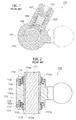
- the driving member 5 of the tilting mechanism 7 includes a fixed side casing 50, a worm shaft 52, a deceleration gear 53, and a male screw shaft member 54.
- the fixed side casing 50 is interposed between lower ends of the pair of suspended portions 41 and is rotatably supported in the tilting direction by a pair of rotating shafts 44 and needle bearings 44a.
- the worm shaft 52 is housed in the fixed side casing 50 and is driven by a tilting electric motor 51.
- the deceleration gear 53 is engaged with the worm shaft 52.
- the male screw shaft member 54 is integrally formed on the deceleration gear 53 so as to extend in an orthogonal direction to an axial direction of the pair of rotating shafts 44.
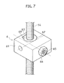
- the female screw member 6 includes a movable side casing 61, a pair of nuts 62 and 63, a wedge member 64, a screw member 65, and a double nut 66.
- the movable side casing 61 is interposed between the brackets 31 of the intermediate jacket 30 and is rotatably supported in the tilting direction by a pair of rotating shafts 60 and needle bearings 60a. Moreover, the movable side casing 61 is provided with a nut container 67 to be penetrated by the male screw shaft member 54, and an insertion hole 68 extending in an orthogonal direction to the nut container 67 and allowing insertion of the wedge member 64 and the screw member 65. A female screw portion 68a to be engaged with the screw member 65 is formed on an inner periphery of the insertion hole 68. The pair of nuts 62 and 63 are inserted into the nut container 67 movably in an axial direction of the male screw shaft member 54. The nut container 67 is also provided with rotation stopper keys 69 for the nuts 62 and 63.
- Female screw portions 62b and 63b to be engaged with the male screw shaft member 54 are respectively formed on inner peripheries of the pair of nuts 62 and 63.
- the pair of nuts 62 and 63 respectively include inclined surfaces 62a and 63a in a portion where their facing surfaces face the insertion hole 68 when the nuts 62 and 63 are contained in the nut container 67.
- These inclined surfaces 62a and 63a form a wedge-shaped recessed portion 64d configured to receive a tip end 64c of the wedge member 64.
- a pair of tapered surfaces 64a and 64b which are provided on the tip end 64c, form a wedge shape such that two surfaces opposed to the tip end 64c come close to each other toward a tip.
- the tip end 64c of the wedge member 64 is formed substantially into a trapezoidal cross section.
- the wedge member 64 is disposed inside the insertion hole 68 such that the tip end 64c protrudes into the nut container 67, and is configured to, when the tip end 64c is inserted into the recessed portion 64d, broaden a clearance between the pair of nuts 62 and 63 while being in contact with the inclined surfaces 62a and 63a constituting the recessed portion 64d.
- the screw member 65 is screwed into the insertion hole 68 and is tightened to perform positioning of the wedge member 64. At this time, the wedge member 64 is positioned such that any biasing forces from the tapered surfaces 64a and 64b of the wedge member 64 is not applied to the inclined surfaces 62a and 63a of the pair of nuts 62 and 63. Meanwhile, a tail end 65a of the screw member 65 protrudes from the insertion hole 68. The screw member 65 is fixed to the movable side casing 61 with the tail end 65a engaged with the double nut 66.
- the male screw shaft member 54 is rotated in a decelerated state by way of the worm shaft 52 and the deceleration gear 53, whereby the pair of nuts 62 and 63 of the female screw member 6 are driven in the axial direction of the male screw shaft member 54.
- the bracket (a movable side bracket) 31 of the intermediate jacket 30 moves relative to the mount bracket (a fixed side bracket) 4 and the respective bolts 42 of the intermediate jacket 30 move along the long holes 43 of the suspended portions 41.
- the jacket unit 3 is rotated in the tilting direction around a lower end in the longitudinal direction. Hence it is possible to perform positioning of the steering shaft 2 in the tilting direction.
- the wedge member 64 is pushed to the pair of nuts 62 and 63 by tightening the screw member 65 and a tightening amount of the screw member 65 is adjusted properly. Thereafter, the screw member 65 is fixed to the movable side casing by using the double nut 66.
- the tip end 64c of the wedge member 64 provided on the movable side casing 61 of the female screw member 6 is fitted in the space between the inclined surfaces 62a and 63a of the pair of nuts 62 and 63.
- the pair of nuts 62 and 63 are pushed and moved to be separated from each other in the axial direction.
- the lower nut 62 moves downward along the male screw shaft member 54 while the upper nut 63 moves upward along the male screw shaft member.
- outside surfaces 62c and 63c of the female screw portions 62b and 63b of the respective nuts 62 and 63 come into contact with and get held by a male screw portion 54a of the male screw shaft member 54. Hence the backlash between the male screw shaft member 54 and the pair of nuts 62 and 63 is eliminated.
- the pair of nuts 62 and 63 are respectively pushed and moved to be separated from each other in the axial direction by the wedge member 64 provided on the movable side casing 61 of the female screw member 6 so that the backlash between the male screw shaft member 54 and the pair of nuts 62 and 63 can be eliminated.
- a load in the axial direction of the male screw shaft member 54 acting on the pair of nuts 62 and 63 of the female screw member 6 is received by the wedge member 64 whose tip end 64c is inserted between the pair of nuts 62 and 63, and is then transmitted to the movable side casing 61.
- the wedge member 64 and the screw member 65 are inserted into the insertion hole 68 of the movable side casing 61, and the screw member 65 engaged the female screw portion 68a of the insertion hole 68 is tightened as appropriate.
- the wedge member 64 adjusts amounts of movement of the pair of nuts 62 and 63 in the axial direction of the male screw shaft member 54, so that the wedge member 64 does not apply any biasing force to the nuts 62 and 63.
- the backlash between the male screw shaft member 54 and the pair of nuts 62 and 63 can be adjusted easily, and the male screw shaft member 54 can be made easily rotatable relative to the pair of nuts 62 and 63 by reducing rotational resistance between the male screw shaft member 54 and the pair of nuts 62 and 63. Hence it is possible to perform positioning of the steering shaft in the tilting direction smoothly.
- this embodiment does not employ a configuration to eliminate the backlash by biasing and holding the nuts onto the male screw shaft member using biasing means. Accordingly, it is possible to avoid an increase in the load applied to the driving means by the biasing force of the biasing means.
- This embodiment has been illustrated as having the structure in which the nuts 62 and 63 of the female screw member 6 and the nut container 67 of the movable side casing 61 are formed in cylindrical shapes, and in which the rotation stopper keys 69 is fit into key grooves between the outer peripheries of the nuts 62 and 63 and the inner periphery of the nut container 67.
- the present invention is not limited only to this structure. It is also possible to prevent rotation of the pair of nuts by forming the pair of nuts of the female screw member as well as the nut container of the movable side casing respectively into different shapes, for example, polygons such as quadrangles.
- the embodiment has described the example of the structure for preventing the backlash of the tilting, mechanism 7 configured to perform positioning of the jacket unit 3 in the tilting direction.
- the present invention is not limited only to this configuration and it is also possible to employ a configuration to prevent a backlash of the telescopic mechanism for performing positioning of the jacket unit in the telescopic direction.
Abstract
Description
- The present invention relates to an electric steering column device configured to perform positioning of a steering shaft by driving an electric motor.
- There is disclosed an electric steering column device of this type including a male screw shaft member rotatably supported by any one of a fixed side bracket and a movable side bracket, and a female screw member provided to the other one of the fixed side bracket and the movable side bracket and threadedly engaged with the male screw shaft member. The electric steering column device is configured to perform positioning of a steering shaft in a tilting direction and a telescopic direction by moving the fixed side bracket and the movable side bracket relative to each other in such a way that the female screw member is moved in an axial direction of the male screw shaft member with rotation of the male screw shaft member driven by an electric motor. However, the above-described electric steering column device needs to have a clearance (backlash) for sliding at a portion where the male screw shaft member and the female screw member threadedly engage with each other, and this clearance causes backlash of the steering shaft. Accordingly, there are proposed electric steering column devices which are capable of preventing a backlash between the male screw shaft member and the female screw member (see
Patent Literature 1 andPatent Literature 2, for example). - As shown in
FIG. 1 , asteering column device 100 described inPatent Literature 1 includes a malescrew shaft member 101 and afemale screw member 102, and thefemale screw member 102 and aboss 103 are integrally formed. Theboss 103 includes ahousing hole 104 where to house apressing member 105 pressing an outer peripheral surface of the malescrew shaft member 101 in a direction of an internal diameter of thefemale screw member 102, acoil spring 106 biasing the pressingmember 105 toward the malescrew shaft member 101, and anadjustment screw 107 screwed in theboss 103 to adjust a biasing force of thecoil spring 106. - In the above-described configuration, the
adjustment screw 107 housed in thehousing hole 104 of theboss 103 is appropriately adjusted by screwed toward thepressing member 105 so as to allow thepressing member 105 to press the outer peripheral surface of the malescrew shaft member 101 in the direction of the internal diameter of thefemale screw member 102 by using the biasing force of thecoil spring 106. Hence it is possible to prevent a backlash between the malescrew shaft member 101 and thefemale screw member 102 and thereby to reduce a backlash of the steering shaft after positioning. - As shown in
FIG. 2 , asteering column device 110 described inPatent Literature 2 includes afemale screw member 115 provided with threenuts screw shaft member 111. Theintermediate nut 112 is provided with afemale screw portion 112a formed on an inner periphery thereof to be threadedly engaged with the malescrew shaft member 111, and is provided with ring-shaped outer peripheral protrudingportions 112b and recessedportions 112c respectively formed in both ends thereof in an axial direction of the malescrew shaft member 111. The recessedportions 112c are located at inner side of the outer peripheral protrudingportions 112b in the radial direction, anddisc springs 116 are housed in the recessedportions 112c.Annular fixation rings peripheral protruding portions 112b by use offastening bolts 119, and female serrations (not shown) extending in the axial direction of the malescrew shaft member 111 are formed on inner peripheries of therespective fixation rings Female screw portions 113a and 114a to be threadedly engaged with the malescrew shaft member 111 are formed on inner peripheries of theend nuts male serrations end nuts end nuts respective fixation rings screw shaft member 111. - In the above-described configuration, a backlash between the male
screw shaft member 111 and theend nuts intermediate nut 112 and theend nuts disc springs 116, and thereby backlash of the steering shaft is reduced. -
- [Patent Literature 1] Japanese Patent Application Laid-Open No.
2008-51233 - [Patent Literature 2]
WO2008/001721 - The technique described in
Patent Literature 1 is to prevent the relative movement of the malescrew shaft member 101 and thefemale screw member 102 by causing the pressingmember 105 to press the outer peripheral surface of the malescrew shaft member 101 in the direction of the internal diameter. Accordingly, this technique has a problem that when a force in the axial direction is applied to the malescrew shaft member 101, the malescrew shaft member 101 and thefemale screw member 102 slip on each other in the axial direction by an amount equivalent to a backlash therebetween. Moreover, this technique has a problem that since the pressingmember 105 is biased at predetermined strength toward the malescrew shaft member 101, the biasing force of thecoil spring 106 needs to be set large to a certain extent; therefore, an increase in the rotational resistance of the malescrew shaft member 101 leads to an increase in the drive noise of an electric motor for driving the malescrew shaft member 101. Furthermore, this technique has a problem that if there is a gap between thehousing hole 104 of theboss 103 and thepressing member 105, thepressing member 105 moves within the gap and causes noise when the malescrew shaft member 101 is rotated. - The technique described in
Patent Literature 2 has a problem that the threeseparate nuts 112 to 114, thefixation rings disc springs 116, and so forth are required and assembly performance is poor due to a large number of the components, and thereby the manufacturing cost increases. - In view of the aforementioned circumstances, an object of the present invention is to provide a steering column device capable of preventing a backlash of a steering shaft after positioning and simplifying a structure.
- In a first aspect of the present invention, a steering column device includes: a male screw shaft member rotatably supported by any one of a fixed side bracket and a movable side bracket and provided with a male screw portion extending in an axial direction; and a female screw member provided on the other one of the fixed side bracket and the movable side bracket, wherein the movable side bracket is movable relative to the fixed side bracket in such a way that the female screw member is moved relative to the male screw shaft member by rotating the male screw shaft member, the female screw member includes: a casing having a nut container formed of a through hole; a pair of nuts inserted into the nut container so as to be movable in an axial direction of the nut container and not to be rotatable in a circumferential direction of the nut container, the nuts each having a female screw portion through which the male screw shaft member passes while threadedly engaging with the female screw portion; and a wedge member having a tip end in a tapered shape and being disposed on an inner side surface of the nut container with the tip end located between the pair of nuts, and the pair of nuts are separated from each other in the axial direction of the male screw shaft when the tip end of the wedge member is inserted between the pair of nuts, and outside surfaces of the female screw portions of the respective nuts come into contact with and thereby get held by the male screw portion of the male screw shaft member.
- In a second aspect of the present invention, the steering column device of the first aspect further includes: an insertion hole formed of a screw hole passing through a side surface of the casing while extending orthogonally to the nut container; and a screw member inserted into the insertion hole, wherein the tip end of the wedge member is formed into such a wedge shape that two opposed surfaces of the tip end come closer to each other toward the tip, the pair of nuts respectively include inclined surfaces in a portion where their facing surfaces face the insertion hole, the inclined surfaces forming a wedge-shaped recessed portion configured to receive the tip end, the wedge member is disposed between the recessed portion and the screw member in the screw hole, and the wedge member is positioned by screwing the screw member into the insertion hole.
- According to the first aspect, the tip end of the wedge member to be supported by the casing of the female screw member is inserted from the side surface of the nut container into the space between the pair of nuts, and the pair of nuts are respectively pushed and moved to be separated from each other in the axial direction of the male screw shaft member by the wedge member. Hence it is possible to eliminate a backlash between the male screw shaft member and the pair of nuts and thereby to prevent a backlash of the steering shaft after positioning. Moreover, a load in the axial direction of the male screw shaft member acting on the pair of nuts of the female screw member is received by the wedge member whose tip end is inserted into the space between the pair of nuts, and is then transmitted to the casing. In this way, the structure can be simplified without separately providing a structure for fixing the pair of nuts of the female screw member to the casing. Hence it is possible to improve an assembly performance while reducing the number of components and to reduce the manufacturing cost.
- According to the second aspect, the wedge member and the screw member are inserted into the insertion hole of the casing, and the wedge member is positioned with the screw member tightened as appropriate. In this way, an amount of separation between the pair of nuts in the axial direction is adjusted. Thus, the backlash between the male screw shaft member and the pair of nuts can be adjusted easily, and the male screw shaft member can be made easily rotatable relative to the pair of nuts by eliminating a biasing force to the pair of nuts. Hence it is possible to perform positioning of the steering shaft smoothly.
-
-
FIG. 1 is a cross-sectional view showing a first conventional example of a steering column device. -
FIG. 2 is a cross-sectional view showing a second conventional example of a steering column device. -
FIG. 3 is an exploded perspective view of a steering column device showing an embodiment of the present invention. -
FIG. 4 is an enlarged exploded perspective view illustrating substantial part of the steering column device, showing the embodiment of the present invention. -
FIG. 5 is a cross-sectional view taken along an axial direction of the steering column device, showing the embodiment of the present invention. -
FIG. 6 is a cross-sectional view taken along a VI-VI line inFIG. 5 , showing the embodiment of the present invention. -
FIG. 7 is a perspective view illustrating a male screw shaft member and a female screw member, showing the embodiment of the present invention. -
FIG. 8 is a plan view illustrating a male screw shaft member and a female screw member, showing the embodiment of the present invention. -
FIG. 9A is a front view of a wedge member andFIG. 9B is a side view of the wedge member, showing the embodiment of the present invention. -
FIG. 10 is a cross-sectional view illustrating a state before activation of the wedge member, showing the embodiment of the present invention. -
FIG. 11 is an enlarged cross-sectional view illustrating a XI part inFIG. 10 , showing the embodiment of the present invention. -
FIG. 12 is a cross-sectional view illustrating a state after activation of the wedge member, showing the embodiment of the present invention. -
FIG. 13 is an enlarged cross-sectional view illustrating a XIII part inFIG. 12 , showing the embodiment of the present invention. - An embodiment of the present invention will be described below with reference to the accompanying drawings. As shown in
FIG. 3 to FIG. 13 , asteering column device 1 of this embodiment includes: asteering shaft 2 configured to fix a steering wheel (not shown) to an upper end in an axial direction; ajacket unit 3 provided with anupper jacket 32, anintermediate jacket 30, and alower jacket 33 rotatably supporting thesteering shaft 2; amount bracket 4 provided with afixation unit 40 to be fixed to a car body (not shown) and a pair of suspendedportions 41 suspending from thefixation unit 40; atilting mechanism 7 provided with adriving member 5 and afemale screw member 6 and configured to perform positioning of thejacket unit 3 in a tilting direction; and atelescopic mechanism 8 configured to perform positioning of thejacket unit 3 in a telescopic direction. - The
jacket unit 3 extends in an axial direction of thesteering shaft 2. Meanwhile, a lower end in a longitudinal direction of thejacket unit 3 is supported by a car body (not shown) through atilt bracket 34. In this way, theentire jacket unit 3 is rotatable in the tilting direction. Theintermediate jacket 30 of thejacket unit 3 is located between the pair of suspendedportions 41 and is provided with a pair ofbrackets 31 respectively extending downward. Moreover, a pair ofbolts 42 as tilt guides to be respectively inserted into tiltinglong holes 43 provided in the pair of suspendedportions 41 are attached to theintermediate jacket 30. Biasing members such as disk springs 45 are provided between the pair ofbolts 42 and thebrackets 31 of theintermediate jacket 30 so that the biasing members can prevent a backlash in a right-left direction of thesteering shaft 2 as shown inFIG. 6 . - The driving
member 5 of thetilting mechanism 7 includes a fixedside casing 50, aworm shaft 52, adeceleration gear 53, and a malescrew shaft member 54. The fixedside casing 50 is interposed between lower ends of the pair of suspendedportions 41 and is rotatably supported in the tilting direction by a pair ofrotating shafts 44 andneedle bearings 44a. Theworm shaft 52 is housed in the fixedside casing 50 and is driven by a tiltingelectric motor 51. Thedeceleration gear 53 is engaged with theworm shaft 52. The malescrew shaft member 54 is integrally formed on thedeceleration gear 53 so as to extend in an orthogonal direction to an axial direction of the pair ofrotating shafts 44. - The
female screw member 6 includes amovable side casing 61, a pair ofnuts wedge member 64, ascrew member 65, and adouble nut 66. - The
movable side casing 61 is interposed between thebrackets 31 of theintermediate jacket 30 and is rotatably supported in the tilting direction by a pair ofrotating shafts 60 andneedle bearings 60a. Moreover, themovable side casing 61 is provided with anut container 67 to be penetrated by the malescrew shaft member 54, and aninsertion hole 68 extending in an orthogonal direction to thenut container 67 and allowing insertion of thewedge member 64 and thescrew member 65. Afemale screw portion 68a to be engaged with thescrew member 65 is formed on an inner periphery of theinsertion hole 68. The pair ofnuts nut container 67 movably in an axial direction of the malescrew shaft member 54. Thenut container 67 is also provided withrotation stopper keys 69 for the nuts 62 and 63. -
Female screw portions screw shaft member 54 are respectively formed on inner peripheries of the pair ofnuts nuts inclined surfaces insertion hole 68 when the nuts 62 and 63 are contained in thenut container 67. Theseinclined surfaces portion 64d configured to receive a tip end 64c of thewedge member 64. - In the
wedge member 64, a pair of taperedsurfaces FIG. 9A and FIG. 9B , the tip end 64c of thewedge member 64 is formed substantially into a trapezoidal cross section. Thewedge member 64 is disposed inside theinsertion hole 68 such that the tip end 64c protrudes into thenut container 67, and is configured to, when the tip end 64c is inserted into the recessedportion 64d, broaden a clearance between the pair ofnuts inclined surfaces portion 64d. - The
screw member 65 is screwed into theinsertion hole 68 and is tightened to perform positioning of thewedge member 64. At this time, thewedge member 64 is positioned such that any biasing forces from the taperedsurfaces wedge member 64 is not applied to theinclined surfaces nuts tail end 65a of thescrew member 65 protrudes from theinsertion hole 68. Thescrew member 65 is fixed to themovable side casing 61 with thetail end 65a engaged with thedouble nut 66. - According to the above-described configuration, when the tilting
electric motor 51 is rotated for positioning thesteering shaft 2 in the tilting direction, the malescrew shaft member 54 is rotated in a decelerated state by way of theworm shaft 52 and thedeceleration gear 53, whereby the pair ofnuts female screw member 6 are driven in the axial direction of the malescrew shaft member 54. In this way, the bracket (a movable side bracket) 31 of theintermediate jacket 30 moves relative to the mount bracket (a fixed side bracket) 4 and therespective bolts 42 of theintermediate jacket 30 move along thelong holes 43 of the suspendedportions 41. As a consequence, thejacket unit 3 is rotated in the tilting direction around a lower end in the longitudinal direction. Hence it is possible to perform positioning of thesteering shaft 2 in the tilting direction. - By the way, firstly in a state before tightening of the
screw member 65 as shown inFIG. 10 and FIG. 11 , the tip end 64c of thewedge member 64 is not engaged with theinclined surfaces nuts nuts female screw portions screw shaft member 54. That is to say, a backlash occurs between the malescrew shaft member 54 and the pair ofnuts - Subsequently, as shown in
FIG. 12 and FIG. 13 , thewedge member 64 is pushed to the pair ofnuts screw member 65 and a tightening amount of thescrew member 65 is adjusted properly. Thereafter, thescrew member 65 is fixed to the movable side casing by using thedouble nut 66. - By pushing the
wedge member 64 toward the pair ofnuts screw member 65 as described above, the tip end 64c of thewedge member 64 provided on themovable side casing 61 of thefemale screw member 6 is fitted in the space between theinclined surfaces nuts nuts lower nut 62 moves downward along the malescrew shaft member 54 while theupper nut 63 moves upward along the male screw shaft member. That is to say, outside surfaces 62c and 63c of thefemale screw portions respective nuts male screw portion 54a of the malescrew shaft member 54. Hence the backlash between the malescrew shaft member 54 and the pair ofnuts - According to this embodiment, the pair of
nuts wedge member 64 provided on themovable side casing 61 of thefemale screw member 6 so that the backlash between the malescrew shaft member 54 and the pair ofnuts steering shaft 2 after positioning. Moreover, a load in the axial direction of the malescrew shaft member 54 acting on the pair ofnuts female screw member 6 is received by thewedge member 64 whose tip end 64c is inserted between the pair ofnuts movable side casing 61. Therefore, it is possible to simplify the structure without separately providing a structure for fixing the pair ofnuts movable side casing 61. Moreover, it is possible to improve an assembly performance while reducing the number of components and thereby to reduce the manufacturing cost. - Moreover, in this embodiment, the
wedge member 64 and thescrew member 65 are inserted into theinsertion hole 68 of themovable side casing 61, and thescrew member 65 engaged thefemale screw portion 68a of theinsertion hole 68 is tightened as appropriate. In this way, thewedge member 64 adjusts amounts of movement of the pair ofnuts screw shaft member 54, so that thewedge member 64 does not apply any biasing force to the nuts 62 and 63. Thus, the backlash between the malescrew shaft member 54 and the pair ofnuts screw shaft member 54 can be made easily rotatable relative to the pair ofnuts screw shaft member 54 and the pair ofnuts - Furthermore, this embodiment does not employ a configuration to eliminate the backlash by biasing and holding the nuts onto the male screw shaft member using biasing means. Accordingly, it is possible to avoid an increase in the load applied to the driving means by the biasing force of the biasing means.
- This embodiment has been illustrated as having the structure in which the nuts 62 and 63 of the
female screw member 6 and thenut container 67 of themovable side casing 61 are formed in cylindrical shapes, and in which therotation stopper keys 69 is fit into key grooves between the outer peripheries of the nuts 62 and 63 and the inner periphery of thenut container 67. However, the present invention is not limited only to this structure. It is also possible to prevent rotation of the pair of nuts by forming the pair of nuts of the female screw member as well as the nut container of the movable side casing respectively into different shapes, for example, polygons such as quadrangles. - Moreover, the embodiment has described the example of the structure for preventing the backlash of the tilting,
mechanism 7 configured to perform positioning of thejacket unit 3 in the tilting direction. However, the present invention is not limited only to this configuration and it is also possible to employ a configuration to prevent a backlash of the telescopic mechanism for performing positioning of the jacket unit in the telescopic direction. - It is to be noted that entire contents of Japanese Patent Application No.
2010-167900 (filed on July 27, 2010 - The present invention is not limited only to the above-described embodiment but can also be embodied by various other aspects by making appropriate modifications.
Claims (2)
- A steering column device, comprising:a male screw shaft member rotatably supported by any one of a fixed side bracket and a movable side bracket and provided with a male screw portion extending in an axial direction of the male screw shaft member; anda female screw member provided on the other one of the fixed side bracket and the movable side bracket,wherein the movable side bracket is movable relative to the fixed side bracket in such a manner that the female screw member is moved relative to the male screw shaft member by rotating the male screw shaft member,wherein the female screw member comprises:a casing having a nut container formed of a through hole;a pair of nuts inserted into the nut container so as to be movable in an axial direction of the nut container and not to be rotatable in a circumferential direction of the nut container, the nuts each having a female screw portion through which the male screw shaft member passes while threadedly engaging with the female screw portion; anda wedge member having a tip end in a tapered shape and being disposed on an inner side surface of the nut container so that the tip end of the wedge member is located between the pair of nuts,thereby the pair of nuts are separated from each other in the axial direction of the male screw shaft when the tip end of the wedge member is inserted between the pair of nuts, and outside surfaces of the female screw portions of the respective nuts come into contact with and thereby get held by the male screw portion of the male screw shaft member.
- The steering column device according to claim 1, further comprising:an insertion hole formed of a screw hole passing through a side surface of the casing while extending orthogonally to the nut container; anda screw member inserted into the insertion hole,wherein the tip end of the wedge member is formed into such a wedge shape that two opposed surfaces of the tip end come closer to each other toward the tip,wherein the pair of nuts respectively include inclined surfaces in a portion where their facing surfaces face the insertion hole, the inclined surfaces forming a wedge-shaped recessed portion configured to receive the tip end of the wedge member,wherein the wedge member is disposed between the recessed portion and the screw member in the screw hole, andwherein the wedge member is positioned by screwing the screw member into the insertion hole.
Applications Claiming Priority (1)
| Application Number | Priority Date | Filing Date | Title |
|---|---|---|---|
| JP2010167900A JP5674367B2 (en) | 2010-07-27 | 2010-07-27 | Steering column device |
Publications (3)
| Publication Number | Publication Date |
|---|---|
| EP2412607A2 true EP2412607A2 (en) | 2012-02-01 |
| EP2412607A3 EP2412607A3 (en) | 2013-12-11 |
| EP2412607B1 EP2412607B1 (en) | 2016-03-09 |
Family
ID=44883515
Family Applications (1)
| Application Number | Title | Priority Date | Filing Date |
|---|---|---|---|
| EP11175481.8A Not-in-force EP2412607B1 (en) | 2010-07-27 | 2011-07-27 | Steering column device |
Country Status (3)
| Country | Link |
|---|---|
| US (1) | US8640567B2 (en) |
| EP (1) | EP2412607B1 (en) |
| JP (1) | JP5674367B2 (en) |
Cited By (2)
| Publication number | Priority date | Publication date | Assignee | Title |
|---|---|---|---|---|
| DE102014103879A1 (en) | 2014-03-21 | 2015-09-24 | Thyssenkrupp Presta Ag | Steering column for a motor vehicle, threaded rod and spindle nut |
| DE102015212448A1 (en) * | 2015-07-02 | 2017-01-05 | Zf Friedrichshafen Ag | Spindle drive and actuator with a spindle drive |
Families Citing this family (8)
| Publication number | Priority date | Publication date | Assignee | Title |
|---|---|---|---|---|
| US8955407B2 (en) * | 2011-05-30 | 2015-02-17 | Nsk Ltd. | Steering apparatus |
| KR102190492B1 (en) * | 2015-03-02 | 2020-12-14 | 주식회사 만도 | Steering Column for Vehicle |
| WO2017165633A1 (en) * | 2016-03-23 | 2017-09-28 | Nsk Americas, Inc. | Integrated ball screw linear actuator |
| US10446428B2 (en) * | 2017-03-14 | 2019-10-15 | Applied Materials, Inc. | Load port operation in electronic device manufacturing apparatus, systems, and methods |
| KR102274121B1 (en) * | 2017-04-03 | 2021-07-06 | 현대자동차주식회사 | Motor-driven steering column device for vehicle |
| JP6882120B2 (en) * | 2017-08-28 | 2021-06-02 | 富士機工株式会社 | Electric steering column device |
| JP2019172002A (en) | 2018-03-28 | 2019-10-10 | 富士機工株式会社 | Steering column device |
| JP2021020550A (en) * | 2019-07-26 | 2021-02-18 | 富士機工株式会社 | Steering column device |
Citations (1)
| Publication number | Priority date | Publication date | Assignee | Title |
|---|---|---|---|---|
| JP2010167900A (en) | 2009-01-22 | 2010-08-05 | Toyota Boshoku Corp | Onboard microphone device |
Family Cites Families (16)
| Publication number | Priority date | Publication date | Assignee | Title |
|---|---|---|---|---|
| JPH0529979Y2 (en) * | 1987-04-17 | 1993-07-30 | ||
| JPH04106079U (en) * | 1991-02-26 | 1992-09-11 | 光洋精工株式会社 | electric steering device |
| US5285696A (en) * | 1992-09-21 | 1994-02-15 | Answer Products, Inc. | Bar end assembly attachable to the steerer bars of bicycle handlebar systems |
| JPH0960703A (en) * | 1995-08-29 | 1997-03-04 | Aisin Seiki Co Ltd | Drive device |
| US6698301B2 (en) * | 1998-12-29 | 2004-03-02 | Rexroth Star Gmbh | Screw drive with rolling elements, and method of assembly |
| US6119541A (en) * | 1999-03-25 | 2000-09-19 | Micron Electronics, Inc. | Methods for adjusting a lead screw nut and a nut for adjustably engaging a lead screw |
| JP2001124174A (en) * | 1999-10-28 | 2001-05-08 | Isel Co Ltd | Feed screw mechanism and nut body used therefor |
| US20040194570A1 (en) * | 2002-03-20 | 2004-10-07 | Masaki Tomaru | Electric steering column device |
| US6955371B2 (en) * | 2003-11-17 | 2005-10-18 | Bear Corporation | Clamping stem |
| US7841251B2 (en) * | 2004-10-01 | 2010-11-30 | Tritex Corporation | Antiback-lash nut |
| JP2007002858A (en) * | 2005-06-21 | 2007-01-11 | Toyota Motor Corp | Ball screw device |
| US20090120229A1 (en) * | 2005-10-18 | 2009-05-14 | Nsk. Ltd. | Steering column device |
| US20090308189A1 (en) | 2006-06-29 | 2009-12-17 | Nsk Ltd. | Steering device |
| JP4894413B2 (en) | 2006-08-24 | 2012-03-14 | 日本精工株式会社 | Steering device |
| JP2008087582A (en) * | 2006-09-29 | 2008-04-17 | Nsk Ltd | Electric telescopic adjustment type steering device |
| JP5161534B2 (en) * | 2007-10-19 | 2013-03-13 | 富士機工株式会社 | Electric tilt steering device |
-
2010
- 2010-07-27 JP JP2010167900A patent/JP5674367B2/en active Active
-
2011
- 2011-07-22 US US13/188,788 patent/US8640567B2/en not_active Expired - Fee Related
- 2011-07-27 EP EP11175481.8A patent/EP2412607B1/en not_active Not-in-force
Patent Citations (1)
| Publication number | Priority date | Publication date | Assignee | Title |
|---|---|---|---|---|
| JP2010167900A (en) | 2009-01-22 | 2010-08-05 | Toyota Boshoku Corp | Onboard microphone device |
Cited By (4)
| Publication number | Priority date | Publication date | Assignee | Title |
|---|---|---|---|---|
| DE102014103879A1 (en) | 2014-03-21 | 2015-09-24 | Thyssenkrupp Presta Ag | Steering column for a motor vehicle, threaded rod and spindle nut |
| WO2015140205A1 (en) * | 2014-03-21 | 2015-09-24 | Thyssenkrupp Presta Ag | Steering column for a motor vehicle, threaded rod and spindle nut |
| DE102015212448A1 (en) * | 2015-07-02 | 2017-01-05 | Zf Friedrichshafen Ag | Spindle drive and actuator with a spindle drive |
| DE102015212448B4 (en) * | 2015-07-02 | 2020-07-02 | Zf Friedrichshafen Ag | Spindle drive and actuator with one spindle drive |
Also Published As
| Publication number | Publication date |
|---|---|
| JP5674367B2 (en) | 2015-02-25 |
| EP2412607B1 (en) | 2016-03-09 |
| US8640567B2 (en) | 2014-02-04 |
| EP2412607A3 (en) | 2013-12-11 |
| JP2012025321A (en) | 2012-02-09 |
| US20120024103A1 (en) | 2012-02-02 |
Similar Documents
| Publication | Publication Date | Title |
|---|---|---|
| EP2412607B1 (en) | Steering column device | |
| EP2261074B1 (en) | Seat reclining apparatus for vehicle | |
| US6761244B2 (en) | Electric power steering apparatus | |
| US8651526B2 (en) | Steering apparatus | |
| EP2572961A1 (en) | Steering apparatus for vehicle | |
| US8739645B2 (en) | Toothed-rack steering gear, and servo steering system equipped with the same | |
| EP2993108B1 (en) | Steering device | |
| US8931790B2 (en) | Push device with clearance compensation for rack-and-pinion steering of a motor vehicle | |
| TW201226261A (en) | Internal motorized bicycle hub | |
| GB2528517A (en) | Worm biasing structure | |
| US10011294B2 (en) | Electric power steering apparatus | |
| KR20170080899A (en) | Structure of bearing holder for electric power steering system | |
| KR20140014714A (en) | Noise reduction type motor driven power steering | |
| CN105711639A (en) | Electric power steering device | |
| JP2003014055A (en) | Backlash adjusting device of worm reduction gear | |
| JP2003278844A (en) | Reduction gear mechanism and electric power steering device using the same | |
| JPWO2020009074A1 (en) | Steering wheel reaction force applying device | |
| JP2012001050A (en) | Electric power steering device | |
| JP2003285747A (en) | Steering device of vehicle | |
| JP6620910B2 (en) | Steering device | |
| US10619718B2 (en) | Worm reducer and method of assembling worm reducer | |
| KR101467027B1 (en) | Reducer | |
| JP2014237416A (en) | Steering column device | |
| JP5122903B2 (en) | Position adjustment type steering device | |
| JP2008114716A (en) | Steering device |
Legal Events
| Date | Code | Title | Description |
|---|---|---|---|
| AK | Designated contracting states |
Kind code of ref document: A2 Designated state(s): AL AT BE BG CH CY CZ DE DK EE ES FI FR GB GR HR HU IE IS IT LI LT LU LV MC MK MT NL NO PL PT RO RS SE SI SK SM TR |
|
| AX | Request for extension of the european patent |
Extension state: BA ME |
|
| PUAI | Public reference made under article 153(3) epc to a published international application that has entered the european phase |
Free format text: ORIGINAL CODE: 0009012 |
|
| PUAL | Search report despatched |
Free format text: ORIGINAL CODE: 0009013 |
|
| AK | Designated contracting states |
Kind code of ref document: A3 Designated state(s): AL AT BE BG CH CY CZ DE DK EE ES FI FR GB GR HR HU IE IS IT LI LT LU LV MC MK MT NL NO PL PT RO RS SE SI SK SM TR |
|
| AX | Request for extension of the european patent |
Extension state: BA ME |
|
| RIC1 | Information provided on ipc code assigned before grant |
Ipc: F16H 25/20 20060101ALI20131105BHEP Ipc: B62D 1/181 20060101AFI20131105BHEP |
|
| 17P | Request for examination filed |
Effective date: 20140521 |
|
| RBV | Designated contracting states (corrected) |
Designated state(s): AL AT BE BG CH CY CZ DE DK EE ES FI FR GB GR HR HU IE IS IT LI LT LU LV MC MK MT NL NO PL PT RO RS SE SI SK SM TR |
|
| 17Q | First examination report despatched |
Effective date: 20141121 |
|
| GRAP | Despatch of communication of intention to grant a patent |
Free format text: ORIGINAL CODE: EPIDOSNIGR1 |
|
| INTG | Intention to grant announced |
Effective date: 20150716 |
|
| INTG | Intention to grant announced |
Effective date: 20151125 |
|
| GRAS | Grant fee paid |
Free format text: ORIGINAL CODE: EPIDOSNIGR3 |
|
| GRAA | (expected) grant |
Free format text: ORIGINAL CODE: 0009210 |
|
| AK | Designated contracting states |
Kind code of ref document: B1 Designated state(s): AL AT BE BG CH CY CZ DE DK EE ES FI FR GB GR HR HU IE IS IT LI LT LU LV MC MK MT NL NO PL PT RO RS SE SI SK SM TR |
|
| REG | Reference to a national code |
Ref country code: GB Ref legal event code: FG4D |
|
| REG | Reference to a national code |
Ref country code: AT Ref legal event code: REF Ref document number: 779245 Country of ref document: AT Kind code of ref document: T Effective date: 20160315 Ref country code: CH Ref legal event code: EP |
|
| REG | Reference to a national code |
Ref country code: IE Ref legal event code: FG4D |
|
| REG | Reference to a national code |
Ref country code: DE Ref legal event code: R096 Ref document number: 602011023794 Country of ref document: DE |
|
| REG | Reference to a national code |
Ref country code: LT Ref legal event code: MG4D |
|
| REG | Reference to a national code |
Ref country code: NL Ref legal event code: MP Effective date: 20160309 |
|
| REG | Reference to a national code |
Ref country code: FR Ref legal event code: PLFP Year of fee payment: 6 |
|
| PG25 | Lapsed in a contracting state [announced via postgrant information from national office to epo] |
Ref country code: NO Free format text: LAPSE BECAUSE OF FAILURE TO SUBMIT A TRANSLATION OF THE DESCRIPTION OR TO PAY THE FEE WITHIN THE PRESCRIBED TIME-LIMIT Effective date: 20160609 Ref country code: HR Free format text: LAPSE BECAUSE OF FAILURE TO SUBMIT A TRANSLATION OF THE DESCRIPTION OR TO PAY THE FEE WITHIN THE PRESCRIBED TIME-LIMIT Effective date: 20160309 Ref country code: FI Free format text: LAPSE BECAUSE OF FAILURE TO SUBMIT A TRANSLATION OF THE DESCRIPTION OR TO PAY THE FEE WITHIN THE PRESCRIBED TIME-LIMIT Effective date: 20160309 Ref country code: ES Free format text: LAPSE BECAUSE OF FAILURE TO SUBMIT A TRANSLATION OF THE DESCRIPTION OR TO PAY THE FEE WITHIN THE PRESCRIBED TIME-LIMIT Effective date: 20160309 Ref country code: GR Free format text: LAPSE BECAUSE OF FAILURE TO SUBMIT A TRANSLATION OF THE DESCRIPTION OR TO PAY THE FEE WITHIN THE PRESCRIBED TIME-LIMIT Effective date: 20160610 |
|
| REG | Reference to a national code |
Ref country code: AT Ref legal event code: MK05 Ref document number: 779245 Country of ref document: AT Kind code of ref document: T Effective date: 20160309 |
|
| PG25 | Lapsed in a contracting state [announced via postgrant information from national office to epo] |
Ref country code: LV Free format text: LAPSE BECAUSE OF FAILURE TO SUBMIT A TRANSLATION OF THE DESCRIPTION OR TO PAY THE FEE WITHIN THE PRESCRIBED TIME-LIMIT Effective date: 20160309 Ref country code: SE Free format text: LAPSE BECAUSE OF FAILURE TO SUBMIT A TRANSLATION OF THE DESCRIPTION OR TO PAY THE FEE WITHIN THE PRESCRIBED TIME-LIMIT Effective date: 20160309 Ref country code: PL Free format text: LAPSE BECAUSE OF FAILURE TO SUBMIT A TRANSLATION OF THE DESCRIPTION OR TO PAY THE FEE WITHIN THE PRESCRIBED TIME-LIMIT Effective date: 20160309 Ref country code: LT Free format text: LAPSE BECAUSE OF FAILURE TO SUBMIT A TRANSLATION OF THE DESCRIPTION OR TO PAY THE FEE WITHIN THE PRESCRIBED TIME-LIMIT Effective date: 20160309 Ref country code: NL Free format text: LAPSE BECAUSE OF FAILURE TO SUBMIT A TRANSLATION OF THE DESCRIPTION OR TO PAY THE FEE WITHIN THE PRESCRIBED TIME-LIMIT Effective date: 20160309 Ref country code: RS Free format text: LAPSE BECAUSE OF FAILURE TO SUBMIT A TRANSLATION OF THE DESCRIPTION OR TO PAY THE FEE WITHIN THE PRESCRIBED TIME-LIMIT Effective date: 20160309 |
|
| PG25 | Lapsed in a contracting state [announced via postgrant information from national office to epo] |
Ref country code: EE Free format text: LAPSE BECAUSE OF FAILURE TO SUBMIT A TRANSLATION OF THE DESCRIPTION OR TO PAY THE FEE WITHIN THE PRESCRIBED TIME-LIMIT Effective date: 20160309 Ref country code: IS Free format text: LAPSE BECAUSE OF FAILURE TO SUBMIT A TRANSLATION OF THE DESCRIPTION OR TO PAY THE FEE WITHIN THE PRESCRIBED TIME-LIMIT Effective date: 20160709 |
|
| PG25 | Lapsed in a contracting state [announced via postgrant information from national office to epo] |
Ref country code: CZ Free format text: LAPSE BECAUSE OF FAILURE TO SUBMIT A TRANSLATION OF THE DESCRIPTION OR TO PAY THE FEE WITHIN THE PRESCRIBED TIME-LIMIT Effective date: 20160309 Ref country code: SM Free format text: LAPSE BECAUSE OF FAILURE TO SUBMIT A TRANSLATION OF THE DESCRIPTION OR TO PAY THE FEE WITHIN THE PRESCRIBED TIME-LIMIT Effective date: 20160309 Ref country code: SK Free format text: LAPSE BECAUSE OF FAILURE TO SUBMIT A TRANSLATION OF THE DESCRIPTION OR TO PAY THE FEE WITHIN THE PRESCRIBED TIME-LIMIT Effective date: 20160309 Ref country code: RO Free format text: LAPSE BECAUSE OF FAILURE TO SUBMIT A TRANSLATION OF THE DESCRIPTION OR TO PAY THE FEE WITHIN THE PRESCRIBED TIME-LIMIT Effective date: 20160309 Ref country code: PT Free format text: LAPSE BECAUSE OF FAILURE TO SUBMIT A TRANSLATION OF THE DESCRIPTION OR TO PAY THE FEE WITHIN THE PRESCRIBED TIME-LIMIT Effective date: 20160711 Ref country code: AT Free format text: LAPSE BECAUSE OF FAILURE TO SUBMIT A TRANSLATION OF THE DESCRIPTION OR TO PAY THE FEE WITHIN THE PRESCRIBED TIME-LIMIT Effective date: 20160309 |
|
| REG | Reference to a national code |
Ref country code: DE Ref legal event code: R097 Ref document number: 602011023794 Country of ref document: DE |
|
| PG25 | Lapsed in a contracting state [announced via postgrant information from national office to epo] |
Ref country code: BE Free format text: LAPSE BECAUSE OF FAILURE TO SUBMIT A TRANSLATION OF THE DESCRIPTION OR TO PAY THE FEE WITHIN THE PRESCRIBED TIME-LIMIT Effective date: 20160309 Ref country code: IT Free format text: LAPSE BECAUSE OF FAILURE TO SUBMIT A TRANSLATION OF THE DESCRIPTION OR TO PAY THE FEE WITHIN THE PRESCRIBED TIME-LIMIT Effective date: 20160309 |
|
| PLBE | No opposition filed within time limit |
Free format text: ORIGINAL CODE: 0009261 |
|
| STAA | Information on the status of an ep patent application or granted ep patent |
Free format text: STATUS: NO OPPOSITION FILED WITHIN TIME LIMIT |
|
| PG25 | Lapsed in a contracting state [announced via postgrant information from national office to epo] |
Ref country code: DK Free format text: LAPSE BECAUSE OF FAILURE TO SUBMIT A TRANSLATION OF THE DESCRIPTION OR TO PAY THE FEE WITHIN THE PRESCRIBED TIME-LIMIT Effective date: 20160309 |
|
| 26N | No opposition filed |
Effective date: 20161212 |
|
| PG25 | Lapsed in a contracting state [announced via postgrant information from national office to epo] |
Ref country code: BG Free format text: LAPSE BECAUSE OF FAILURE TO SUBMIT A TRANSLATION OF THE DESCRIPTION OR TO PAY THE FEE WITHIN THE PRESCRIBED TIME-LIMIT Effective date: 20160609 |
|
| REG | Reference to a national code |
Ref country code: CH Ref legal event code: PL |
|
| GBPC | Gb: european patent ceased through non-payment of renewal fee |
Effective date: 20160727 |
|
| PG25 | Lapsed in a contracting state [announced via postgrant information from national office to epo] |
Ref country code: MC Free format text: LAPSE BECAUSE OF FAILURE TO SUBMIT A TRANSLATION OF THE DESCRIPTION OR TO PAY THE FEE WITHIN THE PRESCRIBED TIME-LIMIT Effective date: 20160309 |
|
| PG25 | Lapsed in a contracting state [announced via postgrant information from national office to epo] |
Ref country code: LI Free format text: LAPSE BECAUSE OF NON-PAYMENT OF DUE FEES Effective date: 20160731 Ref country code: CH Free format text: LAPSE BECAUSE OF NON-PAYMENT OF DUE FEES Effective date: 20160731 |
|
| REG | Reference to a national code |
Ref country code: IE Ref legal event code: MM4A |
|
| PG25 | Lapsed in a contracting state [announced via postgrant information from national office to epo] |
Ref country code: SI Free format text: LAPSE BECAUSE OF FAILURE TO SUBMIT A TRANSLATION OF THE DESCRIPTION OR TO PAY THE FEE WITHIN THE PRESCRIBED TIME-LIMIT Effective date: 20160309 Ref country code: GB Free format text: LAPSE BECAUSE OF NON-PAYMENT OF DUE FEES Effective date: 20160727 |
|
| REG | Reference to a national code |
Ref country code: FR Ref legal event code: PLFP Year of fee payment: 7 |
|
| PG25 | Lapsed in a contracting state [announced via postgrant information from national office to epo] |
Ref country code: IE Free format text: LAPSE BECAUSE OF NON-PAYMENT OF DUE FEES Effective date: 20160727 |
|
| PG25 | Lapsed in a contracting state [announced via postgrant information from national office to epo] |
Ref country code: LU Free format text: LAPSE BECAUSE OF NON-PAYMENT OF DUE FEES Effective date: 20160727 |
|
| PG25 | Lapsed in a contracting state [announced via postgrant information from national office to epo] |
Ref country code: HU Free format text: LAPSE BECAUSE OF FAILURE TO SUBMIT A TRANSLATION OF THE DESCRIPTION OR TO PAY THE FEE WITHIN THE PRESCRIBED TIME-LIMIT; INVALID AB INITIO Effective date: 20110727 Ref country code: CY Free format text: LAPSE BECAUSE OF FAILURE TO SUBMIT A TRANSLATION OF THE DESCRIPTION OR TO PAY THE FEE WITHIN THE PRESCRIBED TIME-LIMIT Effective date: 20160309 |
|
| PG25 | Lapsed in a contracting state [announced via postgrant information from national office to epo] |
Ref country code: MT Free format text: LAPSE BECAUSE OF NON-PAYMENT OF DUE FEES Effective date: 20160731 Ref country code: MK Free format text: LAPSE BECAUSE OF FAILURE TO SUBMIT A TRANSLATION OF THE DESCRIPTION OR TO PAY THE FEE WITHIN THE PRESCRIBED TIME-LIMIT Effective date: 20160309 Ref country code: TR Free format text: LAPSE BECAUSE OF FAILURE TO SUBMIT A TRANSLATION OF THE DESCRIPTION OR TO PAY THE FEE WITHIN THE PRESCRIBED TIME-LIMIT Effective date: 20160309 |
|
| REG | Reference to a national code |
Ref country code: FR Ref legal event code: PLFP Year of fee payment: 8 |
|
| PG25 | Lapsed in a contracting state [announced via postgrant information from national office to epo] |
Ref country code: AL Free format text: LAPSE BECAUSE OF FAILURE TO SUBMIT A TRANSLATION OF THE DESCRIPTION OR TO PAY THE FEE WITHIN THE PRESCRIBED TIME-LIMIT Effective date: 20160309 |
|
| PGFP | Annual fee paid to national office [announced via postgrant information from national office to epo] |
Ref country code: FR Payment date: 20200717 Year of fee payment: 10 Ref country code: DE Payment date: 20200724 Year of fee payment: 10 |
|
| REG | Reference to a national code |
Ref country code: DE Ref legal event code: R119 Ref document number: 602011023794 Country of ref document: DE |
|
| PG25 | Lapsed in a contracting state [announced via postgrant information from national office to epo] |
Ref country code: DE Free format text: LAPSE BECAUSE OF NON-PAYMENT OF DUE FEES Effective date: 20220201 |
|
| PG25 | Lapsed in a contracting state [announced via postgrant information from national office to epo] |
Ref country code: FR Free format text: LAPSE BECAUSE OF NON-PAYMENT OF DUE FEES Effective date: 20210731 |