EP2411717B1 - Protective sleeve for a flexible pipe - Google Patents
Protective sleeve for a flexible pipe Download PDFInfo
- Publication number
- EP2411717B1 EP2411717B1 EP10716568.0A EP10716568A EP2411717B1 EP 2411717 B1 EP2411717 B1 EP 2411717B1 EP 10716568 A EP10716568 A EP 10716568A EP 2411717 B1 EP2411717 B1 EP 2411717B1
- Authority
- EP
- European Patent Office
- Prior art keywords
- rings
- protective sleeve
- opposite
- longitudinal portion
- tapered member
- Prior art date
- Legal status (The legal status is an assumption and is not a legal conclusion. Google has not performed a legal analysis and makes no representation as to the accuracy of the status listed.)
- Active
Links
- 230000001681 protective effect Effects 0.000 title claims description 36
- 229930195733 hydrocarbon Natural products 0.000 claims description 4
- 150000002430 hydrocarbons Chemical class 0.000 claims description 4
- 230000008602 contraction Effects 0.000 claims description 3
- 230000006835 compression Effects 0.000 claims description 2
- 238000007906 compression Methods 0.000 claims description 2
- 239000002861 polymer material Substances 0.000 claims description 2
- 238000005452 bending Methods 0.000 description 12
- 239000004814 polyurethane Substances 0.000 description 5
- 238000009434 installation Methods 0.000 description 3
- 239000000463 material Substances 0.000 description 3
- 239000002184 metal Substances 0.000 description 3
- 229920002635 polyurethane Polymers 0.000 description 3
- 239000003351 stiffener Substances 0.000 description 3
- 230000000903 blocking effect Effects 0.000 description 2
- 239000000470 constituent Substances 0.000 description 2
- 238000000034 method Methods 0.000 description 2
- 229910000831 Steel Inorganic materials 0.000 description 1
- 230000003042 antagnostic effect Effects 0.000 description 1
- 230000000694 effects Effects 0.000 description 1
- 229920001971 elastomer Polymers 0.000 description 1
- 239000000806 elastomer Substances 0.000 description 1
- 239000000835 fiber Substances 0.000 description 1
- 239000012530 fluid Substances 0.000 description 1
- 239000007789 gas Substances 0.000 description 1
- 230000002427 irreversible effect Effects 0.000 description 1
- 239000003949 liquefied natural gas Substances 0.000 description 1
- 238000000465 moulding Methods 0.000 description 1
- 230000007935 neutral effect Effects 0.000 description 1
- 239000003208 petroleum Substances 0.000 description 1
- 239000004033 plastic Substances 0.000 description 1
- 229920003023 plastic Polymers 0.000 description 1
- 238000007665 sagging Methods 0.000 description 1
- 239000010959 steel Substances 0.000 description 1
- XLYOFNOQVPJJNP-UHFFFAOYSA-N water Substances O XLYOFNOQVPJJNP-UHFFFAOYSA-N 0.000 description 1
- 238000003466 welding Methods 0.000 description 1
Images

Classifications
-
- F—MECHANICAL ENGINEERING; LIGHTING; HEATING; WEAPONS; BLASTING
- F16—ENGINEERING ELEMENTS AND UNITS; GENERAL MEASURES FOR PRODUCING AND MAINTAINING EFFECTIVE FUNCTIONING OF MACHINES OR INSTALLATIONS; THERMAL INSULATION IN GENERAL
- F16L—PIPES; JOINTS OR FITTINGS FOR PIPES; SUPPORTS FOR PIPES, CABLES OR PROTECTIVE TUBING; MEANS FOR THERMAL INSULATION IN GENERAL
- F16L35/00—Special arrangements used in connection with end fittings of hoses, e.g. safety or protecting devices
-
- F—MECHANICAL ENGINEERING; LIGHTING; HEATING; WEAPONS; BLASTING
- F16—ENGINEERING ELEMENTS AND UNITS; GENERAL MEASURES FOR PRODUCING AND MAINTAINING EFFECTIVE FUNCTIONING OF MACHINES OR INSTALLATIONS; THERMAL INSULATION IN GENERAL
- F16L—PIPES; JOINTS OR FITTINGS FOR PIPES; SUPPORTS FOR PIPES, CABLES OR PROTECTIVE TUBING; MEANS FOR THERMAL INSULATION IN GENERAL
- F16L1/00—Laying or reclaiming pipes; Repairing or joining pipes on or under water
- F16L1/12—Laying or reclaiming pipes on or under water
- F16L1/123—Devices for the protection of pipes under water
-
- F—MECHANICAL ENGINEERING; LIGHTING; HEATING; WEAPONS; BLASTING
- F16—ENGINEERING ELEMENTS AND UNITS; GENERAL MEASURES FOR PRODUCING AND MAINTAINING EFFECTIVE FUNCTIONING OF MACHINES OR INSTALLATIONS; THERMAL INSULATION IN GENERAL
- F16L—PIPES; JOINTS OR FITTINGS FOR PIPES; SUPPORTS FOR PIPES, CABLES OR PROTECTIVE TUBING; MEANS FOR THERMAL INSULATION IN GENERAL
- F16L57/00—Protection of pipes or objects of similar shape against external or internal damage or wear
- F16L57/02—Protection of pipes or objects of similar shape against external or internal damage or wear against cracking or buckling
Description
La présente invention se rapporte aux manchons de protection destinés à préserver les conduites flexibles utilisées pour le transport de fluides tels des hydrocarbures et notamment du gaz, entre les installations offshore.The present invention relates to protective sleeves intended to preserve the flexible pipes used for the transport of fluids such as hydrocarbons and especially gas, between offshore installations.
De telles conduites sont dites non liées ou liées selon leur structure, faite de couches superposées enroulées. On retrouvera les définitions précises de ces structures dans les « Recommanded Practice for flexible pipe » de l'American Petroleum Institute : API.Such pipes are said to be unbound or linked according to their structure, made of superimposed coiled layers. The precise definitions of these structures can be found in the American Petroleum Institute's " Recommended Practice for flexible pipe ": API.
Plus particulièrement, l'invention porte sur un manchon raidisseur destiné à être monté autour d'une portion longitudinale de conduite flexible, usuellement près d'un embout de la conduite, pour résister à la flexion de ladite portion longitudinale selon une courbure quelconque de manière à préserver celle-ci de tout endommagement irréversible. L'endommagement peut résulter soit d'une flexion excessive de la portion de conduite flexible selon un faible rayon de courbure ou bien de la répétition des flexions, provoquées par les mouvements de la houle ou des courants marins.More particularly, the invention relates to a stiffening sleeve intended to be mounted around a longitudinal portion of flexible pipe, usually near a pipe end, to withstand the bending of said longitudinal portion in any desired curvature. to preserve it from irreversible damage. Damage may result either from excessive bending of the flexible pipe portion at a small radius of curvature or from the repetition of bending, caused by wave or water currents.
Des manchons raidisseurs connus et largement utilisés dans le domaine des conduites pétrolières flexibles sont constitués d'un corps conique moulé dans un matériau plastique, généralement du polyuréthane. Ces manchons raidisseurs ou « bend stiffener » en langue anglaise, sont alors montés autour de la conduite flexible avant l'installation de l'embout. Ils présentent une masse relativement importante de plusieurs centaines de Kg, par exemple 900 Kg. Aussi, la manipulation et l'installation de ce type de manchon sont relativement mal aisées. De plus, ils sont réalisés d'une seule pièce d'un matériau polymérique dont le coût est relativement important et qui requière une technique de moulage adaptée. Un autre inconvénient est celui du remplacement de ce type de manchon raidisseur qui ne peut s'effectuer sans sectionner la section de conduite flexible qui le porte.Stiffening sleeves known and widely used in the field of flexible oil pipes consist of a conical body molded in a plastic material, usually polyurethane. These stiffening sleeves or " bend stiffener " in English, are then mounted around the flexible pipe before installation of the nozzle. They have a relatively large mass of several hundred kg, for example 900 kg. Also, the handling and installation of this type of sleeve are relatively uncomfortable. In addition, they are made of a single piece of a polymeric material whose cost is relatively high and which requires a suitable molding technique. Another disadvantage is that of replacing this type of stiffening sleeve which can not be done without cutting the section of flexible pipe that carries it.
Pour pallier les inconvénients des manchons raidisseurs précités, il a été imaginé d'engager la portion de conduite à travers un ensemble de colliers, lesquels sont distribués à intervalles réguliers sur la longueur de la portion de conduite flexible à renforcer. Ces colliers comprennent des perçages axiaux destinés à recevoir des tiges métalliques flexibles régulièrement distribuées autour de la conduite.To overcome the disadvantages of the aforementioned stiffening sleeves, it has been devised to engage the pipe portion through a set of collars, which are distributed at regular intervals along the length of the flexible pipe portion to be reinforced. These collars include axial drills intended to receive flexible metal rods regularly distributed around the pipe.
Le document
Cependant, lorsque les efforts de flexion exercés sur la portion de conduite sont trop importants les tiges métalliques flambent et le manchon raidisseur se courbe finalement en deçà d'un rayon de courbure acceptable par la conduite, et elle se dégrade.However, when the bending forces exerted on the pipe portion are too large the metal rods are blazing and the stiffening sleeve finally bends within a radius of curvature acceptable by the pipe, and it degrades.
Ainsi, un problème qui se pose et que vise à résoudre la présente invention est de fournir un manchon de protection qui permette non seulement de résister à la flexion de la conduite flexible, mais au-delà, qui permette d'interdire le fléchissement en deçà d'un rayon de courbure limite.Thus, a problem that arises and that aims to solve the present invention is to provide a protective sleeve that not only allows to withstand the flexion of the flexible pipe, but beyond, which allows to prohibit sagging below a limited radius of curvature.
Dans le but de résoudre ce problème, la présente invention propose un manchon de protection apte à être installé autour d'une portion longitudinale de conduite flexible destinée au transport des hydrocarbures, pour résister à la flexion de ladite portion longitudinale selon une courbure quelconque. Ledit manchon comprend un ensemble d'anneaux présentant chacun deux flancs opposés, les anneaux dudit ensemble étant successivement maintenus ensemble coaxialement et les flancs respectivement en regard par une pluralité d'éléments de liaison axiaux élastiquement déformables répartis circulairement entre les flancs desdits anneaux. La flexion de ladite portion longitudinale est alors apte à provoquer la contraction des éléments de liaison situés vers l'intérieur de la courbure et simultanément, l'allongement des éléments de liaison opposés situés vers l'extérieur de la courbure pour résister à la flexion de ladite portion longitudinale de conduite flexible. Selon l'invention, chaque élément de liaison présente deux parties de fixation rigides opposées et un corps élastique déformable interposé entre lesdites deux parties de fixation pour autoriser le mouvement relatif desdites deux parties de fixation en engendrant des forces de rappel sur lesdites parties de fixation ; et lesdites parties de fixation de chaque élément de liaison sont respectivement fixées dans les flancs en regard desdits anneaux, de façon que la flexion de ladite portion longitudinale de conduite soit apte à provoquer la compression dudit corps élastique déformable des éléments de liaison axiaux de l'intérieur de la courbure et la traction des éléments de liaison axiaux de l'extérieur de la courbure pour transmettre les forces de rappels auxdits anneaux.In order to solve this problem, the present invention proposes a protective sleeve adapted to be installed around a longitudinal portion of flexible pipe for the transport of hydrocarbons, to resist bending of said longitudinal portion of any curvature. Said sleeve comprises a set of rings each having two opposite flanks, the rings of said assembly being successively held together coaxially and the flanks respectively opposite by a plurality of elastically deformable axial connecting elements distributed circularly between the flanks of said rings. The bending of said longitudinal portion is then able to cause the contraction of the connecting elements located towards the inside of the curvature and simultaneously, the elongation of the opposite connecting elements situated towards the outside of the curvature to resist bending of said longitudinal portion of flexible pipe. According to the invention, each connecting element has two opposite rigid fixing parts and a deformable elastic body interposed between said two fixing parts to allow the relative movement of said two fixing parts by generating return forces on said fixing parts; and said attachment portions of each link member are respectively fixed in the flanks facing said rings, so that the flexion of said longitudinal pipe portion is able to cause compression of said deformable elastic body of the axial connecting elements of the inside of the curvature and the traction of the axial connecting elements of outside the curvature to transmit the recall forces to said rings.
Ainsi, une caractéristique avantageuse de l'invention réside dans la mise en oeuvre d'éléments de liaison en trois parties, deux parties de fixation rigides, situées aux deux extrémités opposées dudit élément de liaison, et une partie constituée d'un corps élastique déformable, par exemple en matériau polymère, interposé entre lesdites deux parties rigides. De la sorte, lorsque la portion longitudinale fléchie, sous l'effet des mouvements de la mer, les anneaux solidaires de la conduite sont entraînés en mouvement et les portions d'anneaux orientés vers l'intérieur de la courbure se rapprochent les uns des autres et partant, les parties de fixation de chaque élément de liaison se rapprochent l'une de l'autre en comprimant le corps élastique. Ce dernier, en se déformant oppose une résistance à la compression et induit des forces opposées sur les parties de fixation. A l'extrême, le corps élastique comprimé devient également rigide et contribue au blocage des parties de fixation l'une vers l'autre.Thus, an advantageous feature of the invention lies in the implementation of three-part connecting elements, two rigid attachment parts, located at the two opposite ends of said connecting element, and a portion consisting of a deformable elastic body. , for example of polymer material, interposed between said two rigid parts. In this way, when the longitudinal portion bent, under the effect of the movements of the sea, the rings integral with the pipe are driven in motion and the portions of rings oriented towards the interior of the curvature are brought closer to each other and hence the fastening portions of each connecting member are brought closer to each other by compressing the elastic body. The latter, by deforming opposes a compressive strength and induces opposing forces on the fastening parts. At the extreme, the compressed elastic body also becomes rigid and contributes to blocking the fastening parts towards each other.
Ainsi, pour certaines applications, par exemple lorsque la conduite flexible transporte du gaz naturel liquéfié, et pour laquelle de fortes contraintes tendant à provoquer sa flexion s'exercent, il est avantageux de pourvoir la conduite d'un manchon de protection conforme à l'invention, lequel permet de limiter le rayon de courbure de la portion de conduite flexible sur laquelle il est emmanché, à une valeur minimale.Thus, for certain applications, for example when the flexible pipe carries liquefied natural gas, and for which high stresses tending to cause its flexion are exerted, it is advantageous to provide the pipe with a protective sleeve conforming to the invention, which limits the radius of curvature of the flexible pipe portion on which it is fitted to a minimum value.
Un tel manchon de protection est relativement peu coûteux et aussi plus léger que les manchons raidisseurs coniques en polyuréthane usuels. Il est par exemple constitué de modules comprenant un nombre déterminé d'anneaux, assemblables ensuite, ce qui rend plus aisés, son montage sur la conduite et le remplacement de l'un de ses modules comparativement aux solutions de l'art antérieur.Such a protective sleeve is relatively inexpensive and also lighter than conventional polyurethane conical stiffening sleeves. It consists for example of modules comprising a specific number of rings, then assembled, which makes it easier, its mounting on the pipe and the replacement of one of its modules compared to the solutions of the prior art.
Selon un mode de mise en oeuvre de l'invention particulièrement avantageux, lesdits flancs de chaque anneau présentent un rebord circulaire interne situé vers le centre dudit anneau et qui s'étend sensiblement perpendiculairement audit flanc, et lesdits anneaux dudit ensemble d'anneaux sont maintenus rapprochés les uns des autres de façon que la flexion de ladite portion longitudinale soit apte à provoquer, en outre, la mise en contact respectivement des portions de rebord circulaire internes desdits anneaux situés vers l'intérieur de la courbure pour bloquer la flexion de ladite portion longitudinale de conduite. Ainsi, la mise en contact des portions de rebord circulaire internes, permet un blocage mécanique des anneaux vers l'intérieur de la courbure et interdit le fléchissement de la portion de conduite au-delà d'une certaine limite et en deçà d'un rayon de courbure limite. De la sorte, grâce au manchon de protection objet de l'invention, le contrôle de la courbure de la portion de conduite engagé à l'intérieur, est double. La résistance à la flexion du manchon de protection et la limitation de sa courbure permet déjà grâce aux éléments de liaison, de préserver la portion de conduite d'une courbure excessive et au surplus, la forme particulière des anneaux, permet leur contact et un blocage de la flexion du manchon et par conséquent de la conduite.According to a particularly advantageous embodiment of the invention, said flanks of each ring have a circular rim inner ring located towards the center of said ring and which extends substantially perpendicular to said flank, and said rings of said set of rings are kept close together so that the flexion of said longitudinal portion is able to cause, in addition, the contacting respectively the inner circular flange portions of said rings located inwardly of the curvature to block bending of said longitudinal pipe portion. Thus, the contacting of the inner circular flange portions, allows mechanical locking of the rings towards the inside of the curvature and prohibits the bending of the pipe portion beyond a certain limit and within a radius limit curvature. In this way, thanks to the protective sleeve object of the invention, the control of the curvature of the portion of pipe engaged inside, is double. The bending resistance of the protective sleeve and the limitation of its curvature already makes it possible, thanks to the connecting elements, to preserve the pipe portion of an excessive curvature and, moreover, the particular shape of the rings allows their contact and blocking. bending of the sleeve and consequently of the pipe.
Avantageusement, les flancs desdits anneaux présentent une bordure circulaire externe située à l'opposé du centre dudit anneau par rapport audit rebord circulaire interne, et lesdites parties de fixation de chaque élément de liaison sont respectivement fixées dans lesdites bordures circulaires externes. Ainsi, les rebords circulaires internes des anneaux consécutifs sont susceptibles de venir en contact, tandis que les bordures circulaires externes demeurent espacées les une des autres en laissant un espace entre anneaux permettant de recevoir les éléments de liaison axiaux. Préférentiellement, lesdits anneaux sont respectivement formés de deux bagues concentriques encastrées l'une dans l'autre. L'une d'entre elle, la bague interne est plus large et elle est encastrée dans l'autre pour en être totalement solidaire pour former l'anneau.Advantageously, the flanks of said rings have an outer circular edge located opposite the center of said ring relative to said inner circular flange, and said fastening portions of each connecting element are respectively fixed in said outer circular edges. Thus, the inner circular flanges of the consecutive rings are likely to come into contact, while the outer circular edges remain spaced apart from each other leaving a space between rings for receiving the axial connecting elements. Preferably, said rings are respectively formed of two concentric rings embedded one inside the other. One of them, the inner ring is wider and is embedded in the other to be fully integral to form the ring.
De manière préférée, lesdits éléments de liaison sont constitués de silentblocs et lesdites deux parties de fixation rigides opposées comprennent d'une part, une douille de réception présentant un fond et une ouverture et d'autre part, un organe sensiblement tronconique adapté à être engagé à travers ladite ouverture de façon que la pointe dudit organe tronconique soit orienté vers ledit fond, tandis que ledit corps élastique déformable comprend un organe cylindrique creux apte à être engagé à l'intérieur de ladite douille et à recevoir ledit organe tronconique.Preferably, said connecting elements consist of silentblocs and said two opposite rigid attachment parts comprise firstly, a receiving sleeve having a bottom and an opening and secondly, a substantially frustoconical member adapted to be engaged. at through said opening so that the tip of said frustoconical member is oriented towards said bottom, while said deformable elastic body comprises a hollow cylindrical member adapted to be engaged within said sleeve and to receive said frustoconical member.
De plus cet organe cylindrique creux en PU est collé à l'intérieur de la douille, tandis que l'organe tronconique est collé lui à l'intérieur de l'organe cylindrique creux. Le mode de collage, acier sur PU, est suffisamment résistant pour supporter une déformation en traction de l'organe cylindrique creux, lorsque la douille et l'organe tronconique sont écartés l'un de l'autre, sans pour autant provoquer de désolidarisation des trois éléments.In addition this hollow cylindrical PU member is bonded to the inside of the sleeve, while the frustoconical member is bonded to it inside the hollow cylindrical member. The method of bonding, steel to PU, is sufficiently strong to withstand a deformation in tension of the hollow cylindrical member, when the sleeve and the frustoconical member are spaced apart from each other, without causing disconnection of the three elements.
Selon un mode préféré de mise en oeuvre de l'invention, ladite douille de réception présente une tige de douille solidaire dudit fond et qui s'étend à l'extérieur de ladite douille et à l'opposé de ladite ouverture, ladite tige de douille étant destinée à être engagée à travers lesdits anneaux selon une direction axiale pour solidariser ladite douille auxdits anneaux. Par exemple, comme on l'expliquera plus en détail dans la suite de la description, ladite tige de douille traverse ledit anneau de part en part et son extrémité libre est filetée pour recevoir un écrou qui prend appui contre le flanc opposé à celui qui reçoit la douille en appui. De la même façon, ledit organe tronconique présente avantageusement une tige d'organe tronconique solidaire dudit organe tronconique et qui s'étend à l'opposé de ladite pointe, ladite tige d'organe tronconique étant destinée à être engagée à travers lesdits anneaux selon une direction axiale pour solidariser ledit organe tronconique auxdits anneaux.According to a preferred embodiment of the invention, said receiving sleeve has a socket rod integral with said bottom and which extends outside said socket and opposite said opening, said socket rod being intended to be engaged through said rings in an axial direction to secure said sleeve to said rings. For example, as will be explained in more detail in the following description, said bushing rod passes through said ring from one side to the other and its free end is threaded to receive a nut that bears against the flank opposite to that which receives the socket in support. In the same way, said frustoconical member advantageously has a frustoconical member rod integral with said frustoconical member and which extends opposite said tip, said frustoconical member rod being intended to be engaged through said rings in a manner axial direction for securing said frustoconical member to said rings.
En outre, les anneaux dudit ensemble sont chacun avantageusement constitué de deux demi-coquilles assemblées par boulonnage, de manière à pouvoir être remplacés sans démonter l'ensemble du manchon.In addition, the rings of said set are each advantageously constituted by two half-shells assembled by bolting, so as to be replaced without removing the entire sleeve.
D'autres particularités et avantages de l'invention ressortiront à la lecture de la description faite ci-après d'un mode de réalisation particulier de l'invention, donné à titre indicatif mais non limitatif, en référence aux dessins annexés sur lesquels :
- la
Figure 1 est une vue schématique en perspective d'un élément constitutif du manchon de protection selon l'invention; - la
Figure 2 est une vue schématique en vue de côté de deux éléments constitutifs appariés; - la
Figure 3 est une vue schématique en perspective des moyens permettant l'appariement des deux éléments représentés sur laFigure 2 ; - la
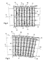
Figure 4 est une vue schématique de côté illustrant un manchon de protection selon l'invention en vue de côté et dans une première position ; et, - la
Figure 5 est une vue schématique de côté du manchon de protection tel qu'illustré sur laFigure 4 dans une seconde position.
- the
Figure 1 is a schematic perspective view of a constituent element of the protective sleeve according to the invention; - the
Figure 2 is a schematic view in side view of two paired constituent elements; - the
Figure 3 is a schematic perspective view of the means allowing the pairing of the two elements represented on theFigure 2 ; - the
Figure 4 is a schematic side view illustrating a protective sleeve according to the invention in side view and in a first position; and, - the
Figure 5 is a schematic side view of the protective sleeve as illustrated on theFigure 4 in a second position.
La
Le manchon de protection conforme à l'invention est constitué d'un ensemble d'anneaux 10 du type illustré sur la
Ces éléments de liaison 32 présentent deux parties de fixation rigides opposées 34, 36 et un corps élastique déformable 38 destiné à être interposé entre les deux parties de fixation 34, 36. L'une des parties de fixation rigide 34 comporte une douille de réception 40 présentant un fond 42 et à l'opposé une ouverture 44. En outre, la douille de réception 40 est munie d'une tige de douille 46 destinée à être solidarisée axialement au fond 42 et à l'opposé de l'ouverture 44. La tige de douille 46 présente une longueur sensiblement supérieure à la largeur axiale l12 de la bague externe 12 et au surplus, son extrémité libre 48 est filetée de manière à pouvoir recevoir un écrou 50. De la sorte, elle peut être engagée à l'intérieur des perçages axiaux 30 de manière à solidariser la douille de réception 40 et la bague externe 12.These connecting
L'autre partie rigide 36 comporte un organe tronconique 52 présentant à la base une collerette 54 et à l'opposé une partie formant pointe 56. L'organe tronconique 52 est également muni d'une tige d'organe tronconique 58 montée solidaire coaxialement dans la base au niveau de la collerette 54. La tige d'organe tronconique 58 s'étend à l'opposé de la partie formant pointe 56 et son extrémité libre 60 est également filetée pour recevoir un second écrou 62. La tige d'organe tronconique 58 présente également une longueur sensiblement supérieure à la largeur axiale l12 de la bague externe 12 et elle est adaptée à être engagée à l'intérieur des perçages axiaux 30 pour solidariser l'organe tronconique 52 à la bague externe 12.The other
En outre, le corps élastique déformable 38 est constitué d'un organe cylindrique creux en matériau polymérique de type élastomère, par exemple en polyuréthane. L'organe cylindrique creux du corps élastique déformable 38 présente une ouverture d'entrée 64 et une paroi de fond opposée 66 le refermant. L'ouverture d'entrée 64 se prolonge par un espace 68 sensiblement tronconique, la base de cet espace étant orientée vers l'ouverture d'entrée 64, tandis que la pointe de cet espace est elle, orientée vers la paroi de fond 66. L'espace 68 sensiblement tronconique, présente des dimensions voisines de celles de l'organe tronconique 52 de manière à pouvoir le recevoir.In addition, the elastic
On se reportera à nouveau sur la
On observera que les huit autres perçages axiaux 30 sont destinés à recevoir, pour l'anneau 10 situé à droite sur la
On se reportera à présent sur les
Lorsque la conduite tubulaire flexible 72 s'étend longitudinalement selon l'axe X, le manchon de protection 74 est à l'équilibre, et les corps élastiques déformables 38 de chacun des éléments de liaison 32, ne sont ni comprimés ni étirés.When the flexible
Lorsque la conduite tubulaire flexible 72 est fléchie, comme illustrée sur la
Ainsi, pour les éléments de liaison 32 situés vers l'intérieur de la courbure, leur organe tronconique 52 tend à venir comprimer le corps élastique déformable 38 à l'intérieur de la douille de réception 40 en autorisant un mouvement axial des anneaux 10 les uns par rapport aux autres. En revanche, du fait de cette contraction, le corps élastique déformable 38 engendre une force de réaction qui tend à l'opposé, à écarter les anneaux 10 les uns des autres. C'est ce qui permet d'offrir une résistance à la flexion de la portion de conduite 71. À l'opposé, vers l'extérieur de la courbure, au dessus de la surface moyenne Sm, l'organe tronconique 72 des éléments de liaison 32 tend à ressortir de la douille de réception 40 et à étirer le corps élastique déformable 38 qui à l'inverse offre également une force de résistance à la traction.Thus, for the connecting
Ainsi, grâce à ces forces antagonistes, vers l'intérieur de la courbure qui tendent à éloigner les anneaux 10 les uns des autres et vers l'extérieur qui tende à les rapprocher, le manchon de protection 74 permet d'offrir une résistance à la flexion de la portion de conduite 71.Thus, thanks to these antagonistic forces, towards the inside of the curvature which tend to move the
Un autre avantage de l'invention, réside dans la mise en contact des rebords 20, 22 des anneaux 10 successifs vers l'intérieur de la courbure, lorsque celle-ci devient trop importante et que les éléments de liaison 32 ne suffisent plus à contrôler cette courbure. Ainsi, les rebords 20 22, au niveau des portions internes 76 d'anneaux 10 viennent successivement en butée les uns contre les autres et bloquent alors la flexion de la portion 71 de conduite flexible 72 emmanchée dans le manchon de protection 74. Ainsi le manchon de protection conforme à l'invention, présente toutes les fonctions d'un raidisseur et au surplus, celle d'un limiteur de courbure au-delà de laquelle la portion de conduite qu'il entoure ne peut être fléchie.Another advantage of the invention lies in bringing the
Par ailleurs, le manchon de protection conforme à l'invention n'est nullement limité à huit anneaux. Il est ainsi prévu de former des manchons de protection incluant bien plus d'anneaux de manière à limiter la courbure de plus longues portions de conduite. Au surplus, le nombre des éléments de liaison 32 pour apparier deux anneaux n'est pas non plus limitatif. On prévoit par exemple d'apparier les anneaux deux à deux au moyen de dix éléments de liaison. Quant au diamètre du manchon de protection, il est bien évidemment adapté au diamètre externe de la conduite flexible à préserver. En conséquence, il est prévu des diamètres d'anneaux inférieurs, par exemple de 0,4 m.Moreover, the protective sleeve according to the invention is not limited to eight rings. It is thus planned to form protective sleeves including many more rings so as to limit the curvature of longer pipe portions. In addition, the number of connecting
En outre un câble 80 s'étend dans la direction axiale le long du manchon de protection. Une première extrémité du câble est fixée sur l'embout de la conduite flexible, tandis que d'autres points d'accrochage sont également distribués le long du manchon de protection. Sur la
En outre, on prévoit des anneaux constitués de deux demi-anneaux ajustables et maintenus ensemble par boulonnage afin de pouvoir remplacer plus aisément les anneaux détériorés de l'ensemble d'anneaux constituant le manchon de protection.In addition, rings are provided consisting of two adjustable half-rings and held together by bolting in order to be able to more easily replace the damaged rings of the set of rings constituting the protective sleeve.
Le mode de réalisation décrit n'est nullement limitatif de l'invention. Notamment, il pourrait être avantageux de prévoir un manchon de protection avec une distribution de raideur répartie le long du manchon différente. Ceci est réalisable aisément en modulant l'espacement entre les anneaux de l'ensemble de protection. Pour cela, il suffit simplement de fournir des éléments de liaisons avec des éléments élastiquement déformables de longueurs différentes. A titre d'exemple, des éléments déformables de courtes longueurs pourraient être installés sur les anneaux les plus proches de l'embout. Puis des éléments de liaisons avec des corps élastiques de plus grandes longueurs pourraient être placés sur les anneaux les plus éloignés de l'embout.The embodiment described is in no way limiting of the invention. In particular, it could be advantageous to provide a protective sleeve with a distribution of stiffness distributed along the different sleeve. This is easily achieved by modulating the spacing between the rings of the protection assembly. For this, it suffices simply to provide connecting elements with elastically deformable elements of different lengths. For example, deformable elements of short length could be installed on the rings closest to the tip. Then connecting elements with elastic bodies of longer lengths could be placed on the rings furthest away from the tip.
Claims (9)
- A protective sleeve that can be fitted around a longitudinal portion of flexible pipe (72) intended for the transportation of hydrocarbons, to withstand the deflection of said longitudinal portion according to any bend, said sleeve comprising a set of rings each having two opposite sides (16, 18), the rings (10) of said set being successively held together coaxially and the sides (16, 18) respectively facing by a plurality of elastically deformable axial link elements (32) distributed circularly between the sides (16, 18) of said rings (10), the deflection of said longitudinal portion being able to provoke the contraction of the link elements (32) situated toward the inside of the bend and simultaneously the elongation of the opposite link elements (32) situated toward the outside of the bend to withstand the deflection of said longitudinal portion of flexible pipe (72);
characterized in that each link element (32) has two opposite rigid fixing parts (34, 36) and a deformable elastic body (38) interposed between said two fixing parts to allow the relative movement of said two fixing parts by generating return forces on said fixing parts;
and in that said fixing parts (34, 36) of each link element (32) are respectively fixed in the facing sides (16, 18) of said rings (10), so that the deflection of said longitudinal portion of pipe can provoke the compression of said deformable elastic body (38) of the axial link elements (32) inside the bend and the traction of the axial link elements (32) on the outside of the bend to transmit the return forces to said rings (10). - The protective sleeve as claimed in claim 1, characterized in that said deformable elastic body (38) is made of polymer material.
- The protective sleeve as claimed in claim 1 or 2, characterized in that said sides (16, 18) of each ring (10) have an internal circular flange (20, 22) situated toward the center of said ring (10), and in that said rings of said set of rings are held close to one another so that the deflection of said longitudinal portion can also provoke the respective coming-into-contact of the internal circular flange portions (20, 22) of said rings (10) situated toward the inside of the bend to block the deflection of said longitudinal portion of pipe (72).
- The protective sleeve as claimed in claim 3, characterized in that the sides (16, 18) of said rings (10) have an outer circular edge (28) situated opposite the center of said ring relative to said internal circular flange (20, 22), and in that said fixing parts (34, 36) of each link element are respectively fixed in said outer circular edges (28).
- The protective sleeve as claimed in claim 3 or 4, characterized in that said rings (10) are respectively formed by two concentric bushings (12, 14) fixed in one another.
- The protective sleeve as claimed in any one of claims 1 to 5, characterized in that said two opposite rigid fixing parts (34, 36) comprise, on the one hand, a receiving bush having a bottom (42) and an opening (44) and, on the other hand, a substantially tapered member (52) adapted to be fitted through said opening (44) so that the point (56) of said tapered member is oriented toward said bottom (42), whereas said deformable elastic body (38) comprises a hollow cylindrical member which can be fitted inside said bush (40) and receive said tapered member (52).
- The protective sleeve as claimed in claim 5, characterized in that said receiving bush (40) has a bush rod (46) fastened to said bottom (42) and which extends outside of said bush and opposite said opening, said bush rod (46) being intended to be fitted through said rings (10) in an axial direction to fasten said bush (40) to said rings.
- The protective sleeve as claimed in claim 5 or 6, characterized in that said tapered member (52) has a tapered member rod (58) fastened to said tapered member and which extends opposite said point (56), said tapered member rod being intended to be fitted through said rings (10) in an axial direction to fasten said tapered member (52) to said rings.
- The protective sleeve as claimed in any one of claims 1 to 8, characterized in that the rings (10) of said set each consist of two half-shells assembled by bolting.
Priority Applications (1)
| Application Number | Priority Date | Filing Date | Title |
|---|---|---|---|
| CY20131101092T CY1114700T1 (en) | 2009-03-24 | 2013-12-03 | PROTECTIVE COVER FOR FLEXIBLE PIPE |
Applications Claiming Priority (2)
| Application Number | Priority Date | Filing Date | Title |
|---|---|---|---|
| FR0901378A FR2943758B1 (en) | 2009-03-24 | 2009-03-24 | PROTECTION SLEEVE FOR FLEXIBLE DRIVING |
| PCT/FR2010/050514 WO2010109124A1 (en) | 2009-03-24 | 2010-03-22 | Protective sleeve for a flexible pipe |
Publications (2)
| Publication Number | Publication Date |
|---|---|
| EP2411717A1 EP2411717A1 (en) | 2012-02-01 |
| EP2411717B1 true EP2411717B1 (en) | 2013-09-04 |
Family
ID=41226804
Family Applications (1)
| Application Number | Title | Priority Date | Filing Date |
|---|---|---|---|
| EP10716568.0A Active EP2411717B1 (en) | 2009-03-24 | 2010-03-22 | Protective sleeve for a flexible pipe |
Country Status (15)
| Country | Link |
|---|---|
| US (1) | US9188266B2 (en) |
| EP (1) | EP2411717B1 (en) |
| CN (1) | CN102439343B (en) |
| AP (1) | AP3175A (en) |
| AU (1) | AU2010227404B2 (en) |
| BR (1) | BRPI1011257B1 (en) |
| CA (1) | CA2755872C (en) |
| CY (1) | CY1114700T1 (en) |
| ES (1) | ES2438502T3 (en) |
| FR (1) | FR2943758B1 (en) |
| MX (1) | MX2011009998A (en) |
| MY (1) | MY159240A (en) |
| NZ (1) | NZ595267A (en) |
| TN (1) | TN2011000476A1 (en) |
| WO (1) | WO2010109124A1 (en) |
Families Citing this family (10)
| Publication number | Priority date | Publication date | Assignee | Title |
|---|---|---|---|---|
| WO2013113316A1 (en) * | 2012-02-02 | 2013-08-08 | National Oilwell Varco Denmark I/S | Bend limiter |
| EP3068967B1 (en) * | 2013-11-14 | 2017-09-27 | Statoil Petroleum AS | Bend stiffener |
| FR3017178B1 (en) * | 2014-02-06 | 2016-09-02 | Delfingen Fr-Anteuil S A | ANNELED TUBULAR SHEATH WITH INTERNAL CLAMPING MEANS |
| CN105317220B (en) * | 2014-07-18 | 2017-05-24 | 中联重科股份有限公司 | Material conveyance hose protecting device, distributing mechanism and concrete pumping equipment |
| US10008840B2 (en) | 2015-07-20 | 2018-06-26 | Magnetic Lifting Technologies US, LLC | Flexible clad protection system |
| US9982800B2 (en) * | 2015-08-12 | 2018-05-29 | Tor Persson | Bending restrictor assembly for permanently bending and restraining ovality of a subsea pipe |
| CN105268695B (en) * | 2015-10-28 | 2018-08-10 | 芜湖市恒浩机械制造有限公司 | A kind of valve dust blower |
| EP3649389A4 (en) * | 2017-08-09 | 2020-07-08 | Tor Persson | Bending restrictor assembly for permanently bending and restraining ovality of a subsea pipe |
| CN111779921B (en) * | 2020-07-03 | 2022-03-22 | 合肥市久环给排水燃气设备有限公司 | Gas pipeline's protector |
| CN115899443B (en) * | 2022-12-24 | 2023-11-21 | 常州松英视液镜有限公司 | Flexible protective sleeve and processing technology thereof |
Family Cites Families (36)
| Publication number | Priority date | Publication date | Assignee | Title |
|---|---|---|---|---|
| US982482A (en) * | 1910-04-27 | 1911-01-24 | William Thomas Donnelly | Flexible pipe. |
| US1677077A (en) * | 1927-09-20 | 1928-07-10 | Burwell B Byers | Hose protector |
| US3323552A (en) * | 1964-09-29 | 1967-06-06 | Honeywell Inc | Deflectable tube |
| US3833267A (en) * | 1972-11-30 | 1974-09-03 | Green Refractories | Liner and process for combating wear in pneumatic transport systems |
| JPS57111904A (en) * | 1980-12-27 | 1982-07-12 | Horiba Ltd | Flexible cable |
| GB2142788B (en) * | 1983-06-08 | 1987-05-20 | British Telecomm | Bend limiter for cables |
| US4527928A (en) * | 1983-07-15 | 1985-07-09 | Texaco Inc. | Protective riser-conductor for offshore structures |
| US4700693A (en) * | 1985-12-09 | 1987-10-20 | Welch Allyn, Inc. | Endoscope steering section |
| IT1186157B (en) * | 1985-12-20 | 1987-11-18 | Pirelli Cavi Spa | DEVICE TO LIMIT THE CURVATURE OF A PORTION OF SUBMARINE CABLE |
| US4722631A (en) * | 1986-05-21 | 1988-02-02 | Musashi Seimitsu Kogyo Kabushiki Kaisha | Ball-and-socket joint with rubber-cushioned ball |
| US4790294A (en) * | 1987-07-28 | 1988-12-13 | Welch Allyn, Inc. | Ball-and-socket bead endoscope steering section |
| US4796607A (en) * | 1987-07-28 | 1989-01-10 | Welch Allyn, Inc. | Endoscope steering section |
| US5005558A (en) * | 1988-05-16 | 1991-04-09 | Kabushiki Kaisha Toshiba | Endoscope |
| US4976288A (en) * | 1989-06-22 | 1990-12-11 | Dynamic Air, Inc. | Tubing bend for pneumatic conveying system |
| US5161828A (en) * | 1991-07-31 | 1992-11-10 | Cooper Industries, Inc. | Break-away flowline fitting |
| GB9123760D0 (en) * | 1991-11-08 | 1992-01-02 | Stockman Anthony J | Optical fibre sheathing |
| US5439323A (en) * | 1993-07-09 | 1995-08-08 | Westinghouse Electric Corporation | Rod and shell composite riser |
| MY123038A (en) * | 1995-07-25 | 2006-05-31 | Impact Surge Sdn Bhd | Apparatus for the combatting of underwater growth on submerged structures |
| NO302786B1 (en) * | 1996-08-14 | 1998-04-20 | Alcatel Kabel Norge As | Böyebegrenser |
| GB9703144D0 (en) * | 1997-02-14 | 1997-04-02 | Tyrer Andrew C R | Bend stiffeners |
| FR2760813B1 (en) * | 1997-03-14 | 1999-04-09 | Coflexip | DEVICE FOR CURVING A FLEXIBLE PIPE |
| US5873817A (en) * | 1997-05-12 | 1999-02-23 | Circon Corporation | Endoscope with resilient deflectable section |
| AUPO711097A0 (en) * | 1997-06-02 | 1997-06-26 | National Valve & Engineering Company Pty. Limited | Hose protector system |
| US6599496B2 (en) * | 1999-04-30 | 2003-07-29 | Chek-Med Systems, Inc. | Endoscopy tissue stain |
| US6095197A (en) * | 1999-10-11 | 2000-08-01 | Cascade Waterworks Manufacturing Co., Inc. | Pipe coupling stiffener |
| TW490386B (en) * | 2000-05-01 | 2002-06-11 | Ashimori Ind Co Ltd | Duct repairing material, repairing structure, and repairing method |
| NL1016610C2 (en) * | 2000-11-15 | 2002-05-16 | Lankhorst Recycling Bv | Protection element for a riser segment. |
| US6561714B1 (en) * | 2000-11-20 | 2003-05-13 | Michael R. Williams | Breakaway joint for subsea components |
| US6878149B2 (en) * | 2002-03-25 | 2005-04-12 | Acueity, Inc. | Apparatus and method for intraductal abalation |
| US7699353B2 (en) * | 2004-05-07 | 2010-04-20 | Deep Down, Inc. | Compliant splice |
| NO20043980A (en) * | 2004-09-23 | 2006-03-13 | Marine Subsea Group As | Bending braces |
| US7451784B2 (en) * | 2005-01-25 | 2008-11-18 | Advanced Drainage Systems, Inc. | Corrugated pipe with perforation protecting cover |
| US7413021B2 (en) * | 2005-03-31 | 2008-08-19 | Schlumberger Technology Corporation | Method and conduit for transmitting signals |
| US7469722B2 (en) * | 2006-12-19 | 2008-12-30 | Norvald Berland | Segmented bend stiffener |
| EP2524147A1 (en) * | 2009-12-14 | 2012-11-21 | Phibre Pty Ltd | Subsea connection system |
| AU2010356066B2 (en) * | 2010-06-21 | 2017-01-05 | Versabar, Inc. | Method and apparatus for elevating a marine platform |
-
2009
- 2009-03-24 FR FR0901378A patent/FR2943758B1/en active Active
-
2010
- 2010-03-22 BR BRPI1011257-0A patent/BRPI1011257B1/en active IP Right Grant
- 2010-03-22 NZ NZ595267A patent/NZ595267A/en unknown
- 2010-03-22 MX MX2011009998A patent/MX2011009998A/en active IP Right Grant
- 2010-03-22 MY MYPI2011004438A patent/MY159240A/en unknown
- 2010-03-22 ES ES10716568.0T patent/ES2438502T3/en active Active
- 2010-03-22 EP EP10716568.0A patent/EP2411717B1/en active Active
- 2010-03-22 US US13/257,743 patent/US9188266B2/en active Active
- 2010-03-22 AU AU2010227404A patent/AU2010227404B2/en active Active
- 2010-03-22 AP AP2011005942A patent/AP3175A/en active
- 2010-03-22 WO PCT/FR2010/050514 patent/WO2010109124A1/en active Application Filing
- 2010-03-22 CA CA2755872A patent/CA2755872C/en active Active
- 2010-03-22 CN CN201080022471.2A patent/CN102439343B/en active Active
-
2011
- 2011-09-21 TN TN2011000476A patent/TN2011000476A1/en unknown
-
2013
- 2013-12-03 CY CY20131101092T patent/CY1114700T1/en unknown
Also Published As
| Publication number | Publication date |
|---|---|
| NZ595267A (en) | 2013-04-26 |
| CY1114700T1 (en) | 2016-10-05 |
| MX2011009998A (en) | 2012-01-20 |
| CN102439343A (en) | 2012-05-02 |
| AP2011005942A0 (en) | 2011-10-31 |
| US9188266B2 (en) | 2015-11-17 |
| EP2411717A1 (en) | 2012-02-01 |
| ES2438502T3 (en) | 2014-01-17 |
| AU2010227404A1 (en) | 2011-10-20 |
| CA2755872C (en) | 2017-03-14 |
| AP3175A (en) | 2015-03-31 |
| CA2755872A1 (en) | 2010-09-30 |
| FR2943758A1 (en) | 2010-10-01 |
| US20120048415A1 (en) | 2012-03-01 |
| FR2943758B1 (en) | 2011-03-25 |
| WO2010109124A1 (en) | 2010-09-30 |
| CN102439343B (en) | 2014-02-26 |
| BRPI1011257A2 (en) | 2016-03-22 |
| MY159240A (en) | 2016-12-30 |
| TN2011000476A1 (en) | 2013-03-27 |
| AU2010227404B2 (en) | 2015-04-02 |
| BRPI1011257B1 (en) | 2019-06-04 |
Similar Documents
| Publication | Publication Date | Title |
|---|---|---|
| EP2411717B1 (en) | Protective sleeve for a flexible pipe | |
| EP3469244B1 (en) | Connection end piece for a flexible line, and associated flexible line and method | |
| EP3014157B1 (en) | Flexible pipe and method | |
| FR3074251A1 (en) | CONNECTING TIP FOR A FLEXIBLE FLUID TRANSPORT DUCT, DRIVING AND METHOD THEREOF | |
| FR3014165A1 (en) | FLEXIBLE DRIVING CONNECTION TIP WITH ANCHORING OF ENHANCED ARMOR YARNS | |
| WO2009147064A1 (en) | Flexible pipe with in-built end pieces | |
| EP1859187B1 (en) | Flexible tube protected against vibrations | |
| EP1678435B1 (en) | Guide tube for a flexible duct for transporting hydrocarbons | |
| WO2009004183A2 (en) | Flexible piping with undulating pipe and external mechanical protection | |
| EP2497172B1 (en) | Turbo machine electrical connection element | |
| EP2379900B1 (en) | Fastening device for hydraulic hoses | |
| EP2788645A1 (en) | Assembly comprising a connection piece and a flexible hose for transporting a cryogenic fluid | |
| EP0517897B1 (en) | Stiffener with reinforced structure | |
| EP1605195B1 (en) | Pipe coupling system and associated method of assembly | |
| FR3021625A1 (en) | FLEXIBLE CONNECTION BETWEEN THE FLOOR STRUCTURE AND THE HULL STRUCTURE OF AN AIRCRAFT. | |
| FR2874072A1 (en) | ANCHORING SYSTEM FOR SURFACE INSTALLATION DRAWN UP ACCORDING TO HIGH FREQUENCY MOVEMENTS | |
| EP3095716B1 (en) | Refuelling connection module for space launcher | |
| EP3674590A1 (en) | Device for securing a member to a pipe, system for securing, installation and method for implementing same | |
| WO2017080857A1 (en) | Module for transporting a fluid and method for connecting a woven structure and an end connector | |
| EP3022477A1 (en) | Connection end piece of a flexible pipe, and associated flexible pipe | |
| WO2009066027A1 (en) | Method for mounting an end piece on a pipe in order to form a connector |
Legal Events
| Date | Code | Title | Description |
|---|---|---|---|
| PUAI | Public reference made under article 153(3) epc to a published international application that has entered the european phase |
Free format text: ORIGINAL CODE: 0009012 |
|
| 17P | Request for examination filed |
Effective date: 20111024 |
|
| AK | Designated contracting states |
Kind code of ref document: A1 Designated state(s): AT BE BG CH CY CZ DE DK EE ES FI FR GB GR HR HU IE IS IT LI LT LU LV MC MK MT NL NO PL PT RO SE SI SK SM TR |
|
| DAX | Request for extension of the european patent (deleted) | ||
| GRAP | Despatch of communication of intention to grant a patent |
Free format text: ORIGINAL CODE: EPIDOSNIGR1 |
|
| RIC1 | Information provided on ipc code assigned before grant |
Ipc: E21B 17/01 20060101ALI20130319BHEP Ipc: F16L 1/12 20060101AFI20130319BHEP Ipc: F16L 57/02 20060101ALI20130319BHEP Ipc: F16L 35/00 20060101ALI20130319BHEP |
|
| INTG | Intention to grant announced |
Effective date: 20130412 |
|
| GRAS | Grant fee paid |
Free format text: ORIGINAL CODE: EPIDOSNIGR3 |
|
| GRAA | (expected) grant |
Free format text: ORIGINAL CODE: 0009210 |
|
| RAP1 | Party data changed (applicant data changed or rights of an application transferred) |
Owner name: TECHNIP FRANCE |
|
| AK | Designated contracting states |
Kind code of ref document: B1 Designated state(s): AT BE BG CH CY CZ DE DK EE ES FI FR GB GR HR HU IE IS IT LI LT LU LV MC MK MT NL NO PL PT RO SE SI SK SM TR |
|
| REG | Reference to a national code |
Ref country code: GB Ref legal event code: FG4D Free format text: NOT ENGLISH |
|
| REG | Reference to a national code |
Ref country code: CH Ref legal event code: EP |
|
| REG | Reference to a national code |
Ref country code: AT Ref legal event code: REF Ref document number: 630732 Country of ref document: AT Kind code of ref document: T Effective date: 20130915 |
|
| RAP2 | Party data changed (patent owner data changed or rights of a patent transferred) |
Owner name: TECHNIP FRANCE |
|
| REG | Reference to a national code |
Ref country code: IE Ref legal event code: FG4D Free format text: LANGUAGE OF EP DOCUMENT: FRENCH |
|
| REG | Reference to a national code |
Ref country code: DE Ref legal event code: R096 Ref document number: 602010010011 Country of ref document: DE Effective date: 20131031 |
|
| REG | Reference to a national code |
Ref country code: NL Ref legal event code: T3 |
|
| REG | Reference to a national code |
Ref country code: AT Ref legal event code: MK05 Ref document number: 630732 Country of ref document: AT Kind code of ref document: T Effective date: 20130904 |
|
| REG | Reference to a national code |
Ref country code: ES Ref legal event code: FG2A Ref document number: 2438502 Country of ref document: ES Kind code of ref document: T3 Effective date: 20140117 |
|
| REG | Reference to a national code |
Ref country code: NO Ref legal event code: T2 Effective date: 20130904 |
|
| PG25 | Lapsed in a contracting state [announced via postgrant information from national office to epo] |
Ref country code: AT Free format text: LAPSE BECAUSE OF FAILURE TO SUBMIT A TRANSLATION OF THE DESCRIPTION OR TO PAY THE FEE WITHIN THE PRESCRIBED TIME-LIMIT Effective date: 20130904 Ref country code: LT Free format text: LAPSE BECAUSE OF FAILURE TO SUBMIT A TRANSLATION OF THE DESCRIPTION OR TO PAY THE FEE WITHIN THE PRESCRIBED TIME-LIMIT Effective date: 20130904 Ref country code: HR Free format text: LAPSE BECAUSE OF FAILURE TO SUBMIT A TRANSLATION OF THE DESCRIPTION OR TO PAY THE FEE WITHIN THE PRESCRIBED TIME-LIMIT Effective date: 20130904 Ref country code: SE Free format text: LAPSE BECAUSE OF FAILURE TO SUBMIT A TRANSLATION OF THE DESCRIPTION OR TO PAY THE FEE WITHIN THE PRESCRIBED TIME-LIMIT Effective date: 20130904 |
|
| REG | Reference to a national code |
Ref country code: LT Ref legal event code: MG4D |
|
| PG25 | Lapsed in a contracting state [announced via postgrant information from national office to epo] |
Ref country code: FI Free format text: LAPSE BECAUSE OF FAILURE TO SUBMIT A TRANSLATION OF THE DESCRIPTION OR TO PAY THE FEE WITHIN THE PRESCRIBED TIME-LIMIT Effective date: 20130904 Ref country code: GR Free format text: LAPSE BECAUSE OF FAILURE TO SUBMIT A TRANSLATION OF THE DESCRIPTION OR TO PAY THE FEE WITHIN THE PRESCRIBED TIME-LIMIT Effective date: 20131205 Ref country code: LV Free format text: LAPSE BECAUSE OF FAILURE TO SUBMIT A TRANSLATION OF THE DESCRIPTION OR TO PAY THE FEE WITHIN THE PRESCRIBED TIME-LIMIT Effective date: 20130904 Ref country code: PL Free format text: LAPSE BECAUSE OF FAILURE TO SUBMIT A TRANSLATION OF THE DESCRIPTION OR TO PAY THE FEE WITHIN THE PRESCRIBED TIME-LIMIT Effective date: 20130904 Ref country code: SI Free format text: LAPSE BECAUSE OF FAILURE TO SUBMIT A TRANSLATION OF THE DESCRIPTION OR TO PAY THE FEE WITHIN THE PRESCRIBED TIME-LIMIT Effective date: 20130904 |
|
| PG25 | Lapsed in a contracting state [announced via postgrant information from national office to epo] |
Ref country code: CZ Free format text: LAPSE BECAUSE OF FAILURE TO SUBMIT A TRANSLATION OF THE DESCRIPTION OR TO PAY THE FEE WITHIN THE PRESCRIBED TIME-LIMIT Effective date: 20130904 Ref country code: RO Free format text: LAPSE BECAUSE OF FAILURE TO SUBMIT A TRANSLATION OF THE DESCRIPTION OR TO PAY THE FEE WITHIN THE PRESCRIBED TIME-LIMIT Effective date: 20130904 Ref country code: EE Free format text: LAPSE BECAUSE OF FAILURE TO SUBMIT A TRANSLATION OF THE DESCRIPTION OR TO PAY THE FEE WITHIN THE PRESCRIBED TIME-LIMIT Effective date: 20130904 Ref country code: IS Free format text: LAPSE BECAUSE OF FAILURE TO SUBMIT A TRANSLATION OF THE DESCRIPTION OR TO PAY THE FEE WITHIN THE PRESCRIBED TIME-LIMIT Effective date: 20140104 Ref country code: SK Free format text: LAPSE BECAUSE OF FAILURE TO SUBMIT A TRANSLATION OF THE DESCRIPTION OR TO PAY THE FEE WITHIN THE PRESCRIBED TIME-LIMIT Effective date: 20130904 |
|
| REG | Reference to a national code |
Ref country code: DE Ref legal event code: R097 Ref document number: 602010010011 Country of ref document: DE |
|
| PG25 | Lapsed in a contracting state [announced via postgrant information from national office to epo] |
Ref country code: PT Free format text: LAPSE BECAUSE OF FAILURE TO SUBMIT A TRANSLATION OF THE DESCRIPTION OR TO PAY THE FEE WITHIN THE PRESCRIBED TIME-LIMIT Effective date: 20140106 |
|
| PLBE | No opposition filed within time limit |
Free format text: ORIGINAL CODE: 0009261 |
|
| STAA | Information on the status of an ep patent application or granted ep patent |
Free format text: STATUS: NO OPPOSITION FILED WITHIN TIME LIMIT |
|
| 26N | No opposition filed |
Effective date: 20140605 |
|
| REG | Reference to a national code |
Ref country code: DE Ref legal event code: R097 Ref document number: 602010010011 Country of ref document: DE Effective date: 20140605 |
|
| PG25 | Lapsed in a contracting state [announced via postgrant information from national office to epo] |
Ref country code: DK Free format text: LAPSE BECAUSE OF FAILURE TO SUBMIT A TRANSLATION OF THE DESCRIPTION OR TO PAY THE FEE WITHIN THE PRESCRIBED TIME-LIMIT Effective date: 20130904 |
|
| REG | Reference to a national code |
Ref country code: DE Ref legal event code: R119 Ref document number: 602010010011 Country of ref document: DE |
|
| PG25 | Lapsed in a contracting state [announced via postgrant information from national office to epo] |
Ref country code: LU Free format text: LAPSE BECAUSE OF FAILURE TO SUBMIT A TRANSLATION OF THE DESCRIPTION OR TO PAY THE FEE WITHIN THE PRESCRIBED TIME-LIMIT Effective date: 20140322 |
|
| REG | Reference to a national code |
Ref country code: CH Ref legal event code: PL |
|
| REG | Reference to a national code |
Ref country code: FR Ref legal event code: ST Effective date: 20141128 |
|
| REG | Reference to a national code |
Ref country code: IE Ref legal event code: MM4A Ref country code: DE Ref legal event code: R119 Ref document number: 602010010011 Country of ref document: DE Effective date: 20141001 |
|
| PG25 | Lapsed in a contracting state [announced via postgrant information from national office to epo] |
Ref country code: LI Free format text: LAPSE BECAUSE OF NON-PAYMENT OF DUE FEES Effective date: 20140331 Ref country code: CH Free format text: LAPSE BECAUSE OF NON-PAYMENT OF DUE FEES Effective date: 20140331 Ref country code: IE Free format text: LAPSE BECAUSE OF NON-PAYMENT OF DUE FEES Effective date: 20140322 Ref country code: FR Free format text: LAPSE BECAUSE OF NON-PAYMENT OF DUE FEES Effective date: 20140331 Ref country code: DE Free format text: LAPSE BECAUSE OF NON-PAYMENT OF DUE FEES Effective date: 20141001 |
|
| REG | Reference to a national code |
Ref country code: FR Ref legal event code: D3 Effective date: 20150421 |
|
| PGRI | Patent reinstated in contracting state [announced from national office to epo] |
Ref country code: FR Effective date: 20150421 |
|
| PG25 | Lapsed in a contracting state [announced via postgrant information from national office to epo] |
Ref country code: MT Free format text: LAPSE BECAUSE OF FAILURE TO SUBMIT A TRANSLATION OF THE DESCRIPTION OR TO PAY THE FEE WITHIN THE PRESCRIBED TIME-LIMIT Effective date: 20130904 |
|
| REG | Reference to a national code |
Ref country code: FR Ref legal event code: PLFP Year of fee payment: 7 |
|
| PG25 | Lapsed in a contracting state [announced via postgrant information from national office to epo] |
Ref country code: SM Free format text: LAPSE BECAUSE OF FAILURE TO SUBMIT A TRANSLATION OF THE DESCRIPTION OR TO PAY THE FEE WITHIN THE PRESCRIBED TIME-LIMIT Effective date: 20130904 |
|
| PG25 | Lapsed in a contracting state [announced via postgrant information from national office to epo] |
Ref country code: MC Free format text: LAPSE BECAUSE OF FAILURE TO SUBMIT A TRANSLATION OF THE DESCRIPTION OR TO PAY THE FEE WITHIN THE PRESCRIBED TIME-LIMIT Effective date: 20130904 |
|
| PG25 | Lapsed in a contracting state [announced via postgrant information from national office to epo] |
Ref country code: BG Free format text: LAPSE BECAUSE OF FAILURE TO SUBMIT A TRANSLATION OF THE DESCRIPTION OR TO PAY THE FEE WITHIN THE PRESCRIBED TIME-LIMIT Effective date: 20130904 |
|
| PG25 | Lapsed in a contracting state [announced via postgrant information from national office to epo] |
Ref country code: HU Free format text: LAPSE BECAUSE OF FAILURE TO SUBMIT A TRANSLATION OF THE DESCRIPTION OR TO PAY THE FEE WITHIN THE PRESCRIBED TIME-LIMIT; INVALID AB INITIO Effective date: 20100322 Ref country code: TR Free format text: LAPSE BECAUSE OF FAILURE TO SUBMIT A TRANSLATION OF THE DESCRIPTION OR TO PAY THE FEE WITHIN THE PRESCRIBED TIME-LIMIT Effective date: 20130904 |
|
| REG | Reference to a national code |
Ref country code: FR Ref legal event code: PLFP Year of fee payment: 8 |
|
| REG | Reference to a national code |
Ref country code: FR Ref legal event code: PLFP Year of fee payment: 9 |
|
| PG25 | Lapsed in a contracting state [announced via postgrant information from national office to epo] |
Ref country code: MK Free format text: LAPSE BECAUSE OF FAILURE TO SUBMIT A TRANSLATION OF THE DESCRIPTION OR TO PAY THE FEE WITHIN THE PRESCRIBED TIME-LIMIT Effective date: 20130904 |
|
| PGFP | Annual fee paid to national office [announced via postgrant information from national office to epo] |
Ref country code: NL Payment date: 20230227 Year of fee payment: 14 |
|
| PGFP | Annual fee paid to national office [announced via postgrant information from national office to epo] |
Ref country code: NO Payment date: 20230223 Year of fee payment: 14 Ref country code: FR Payment date: 20230330 Year of fee payment: 14 |
|
| PGFP | Annual fee paid to national office [announced via postgrant information from national office to epo] |
Ref country code: IT Payment date: 20230307 Year of fee payment: 14 Ref country code: GB Payment date: 20230324 Year of fee payment: 14 Ref country code: CY Payment date: 20230221 Year of fee payment: 14 Ref country code: BE Payment date: 20230316 Year of fee payment: 14 |
|
| PGFP | Annual fee paid to national office [announced via postgrant information from national office to epo] |
Ref country code: ES Payment date: 20230405 Year of fee payment: 14 |
|
| PGFP | Annual fee paid to national office [announced via postgrant information from national office to epo] |
Ref country code: NL Payment date: 20240226 Year of fee payment: 15 |