EP3674590A1 - Device for securing a member to a pipe, system for securing, installation and method for implementing same - Google Patents
Device for securing a member to a pipe, system for securing, installation and method for implementing same Download PDFInfo
- Publication number
- EP3674590A1 EP3674590A1 EP19213990.5A EP19213990A EP3674590A1 EP 3674590 A1 EP3674590 A1 EP 3674590A1 EP 19213990 A EP19213990 A EP 19213990A EP 3674590 A1 EP3674590 A1 EP 3674590A1
- Authority
- EP
- European Patent Office
- Prior art keywords
- strap
- conduit
- compensating member
- strands
- securing
- Prior art date
- Legal status (The legal status is an assumption and is not a legal conclusion. Google has not performed a legal analysis and makes no representation as to the accuracy of the status listed.)
- Granted
Links
- 238000009434 installation Methods 0.000 title claims abstract description 8
- 238000000034 method Methods 0.000 title claims abstract description 7
- 239000013013 elastic material Substances 0.000 claims abstract description 7
- 239000000463 material Substances 0.000 claims description 10
- 239000004033 plastic Substances 0.000 description 5
- 229920003023 plastic Polymers 0.000 description 5
- 239000002184 metal Substances 0.000 description 3
- 239000012815 thermoplastic material Substances 0.000 description 3
- 101710187785 60S ribosomal protein L1-A Proteins 0.000 description 2
- 101710187786 60S ribosomal protein L1-B Proteins 0.000 description 2
- 239000000470 constituent Substances 0.000 description 2
- 230000007423 decrease Effects 0.000 description 2
- 238000007654 immersion Methods 0.000 description 2
- -1 polypropylene Polymers 0.000 description 2
- 229920003225 polyurethane elastomer Polymers 0.000 description 2
- YMHOBZXQZVXHBM-UHFFFAOYSA-N 2,5-dimethoxy-4-bromophenethylamine Chemical compound COC1=CC(CCN)=C(OC)C=C1Br YMHOBZXQZVXHBM-UHFFFAOYSA-N 0.000 description 1
- 239000004743 Polypropylene Substances 0.000 description 1
- 241000545067 Venus Species 0.000 description 1
- 239000002131 composite material Substances 0.000 description 1
- 238000010276 construction Methods 0.000 description 1
- 230000000694 effects Effects 0.000 description 1
- 239000004744 fabric Substances 0.000 description 1
- 229930195733 hydrocarbon Natural products 0.000 description 1
- 150000002430 hydrocarbons Chemical class 0.000 description 1
- 210000000056 organ Anatomy 0.000 description 1
- 229920001155 polypropylene Polymers 0.000 description 1
- 229920002635 polyurethane Polymers 0.000 description 1
- 239000004814 polyurethane Substances 0.000 description 1
- 230000002040 relaxant effect Effects 0.000 description 1
- 229920001169 thermoplastic Polymers 0.000 description 1
- 239000004416 thermosoftening plastic Substances 0.000 description 1
Images


Classifications
-
- F—MECHANICAL ENGINEERING; LIGHTING; HEATING; WEAPONS; BLASTING
- F16—ENGINEERING ELEMENTS AND UNITS; GENERAL MEASURES FOR PRODUCING AND MAINTAINING EFFECTIVE FUNCTIONING OF MACHINES OR INSTALLATIONS; THERMAL INSULATION IN GENERAL
- F16L—PIPES; JOINTS OR FITTINGS FOR PIPES; SUPPORTS FOR PIPES, CABLES OR PROTECTIVE TUBING; MEANS FOR THERMAL INSULATION IN GENERAL
- F16L1/00—Laying or reclaiming pipes; Repairing or joining pipes on or under water
- F16L1/12—Laying or reclaiming pipes on or under water
- F16L1/20—Accessories therefor, e.g. floats, weights
-
- F—MECHANICAL ENGINEERING; LIGHTING; HEATING; WEAPONS; BLASTING
- F16—ENGINEERING ELEMENTS AND UNITS; GENERAL MEASURES FOR PRODUCING AND MAINTAINING EFFECTIVE FUNCTIONING OF MACHINES OR INSTALLATIONS; THERMAL INSULATION IN GENERAL
- F16L—PIPES; JOINTS OR FITTINGS FOR PIPES; SUPPORTS FOR PIPES, CABLES OR PROTECTIVE TUBING; MEANS FOR THERMAL INSULATION IN GENERAL
- F16L3/00—Supports for pipes, cables or protective tubing, e.g. hangers, holders, clamps, cleats, clips, brackets
- F16L3/08—Supports for pipes, cables or protective tubing, e.g. hangers, holders, clamps, cleats, clips, brackets substantially surrounding the pipe, cable or protective tubing
- F16L3/12—Supports for pipes, cables or protective tubing, e.g. hangers, holders, clamps, cleats, clips, brackets substantially surrounding the pipe, cable or protective tubing comprising a member substantially surrounding the pipe, cable or protective tubing
- F16L3/137—Supports for pipes, cables or protective tubing, e.g. hangers, holders, clamps, cleats, clips, brackets substantially surrounding the pipe, cable or protective tubing comprising a member substantially surrounding the pipe, cable or protective tubing and consisting of a flexible band
-
- F—MECHANICAL ENGINEERING; LIGHTING; HEATING; WEAPONS; BLASTING
- F16—ENGINEERING ELEMENTS AND UNITS; GENERAL MEASURES FOR PRODUCING AND MAINTAINING EFFECTIVE FUNCTIONING OF MACHINES OR INSTALLATIONS; THERMAL INSULATION IN GENERAL
- F16L—PIPES; JOINTS OR FITTINGS FOR PIPES; SUPPORTS FOR PIPES, CABLES OR PROTECTIVE TUBING; MEANS FOR THERMAL INSULATION IN GENERAL
- F16L3/00—Supports for pipes, cables or protective tubing, e.g. hangers, holders, clamps, cleats, clips, brackets
- F16L3/08—Supports for pipes, cables or protective tubing, e.g. hangers, holders, clamps, cleats, clips, brackets substantially surrounding the pipe, cable or protective tubing
- F16L3/12—Supports for pipes, cables or protective tubing, e.g. hangers, holders, clamps, cleats, clips, brackets substantially surrounding the pipe, cable or protective tubing comprising a member substantially surrounding the pipe, cable or protective tubing
- F16L3/1211—Supports for pipes, cables or protective tubing, e.g. hangers, holders, clamps, cleats, clips, brackets substantially surrounding the pipe, cable or protective tubing comprising a member substantially surrounding the pipe, cable or protective tubing with a substantially-radial tightening or securing member
-
- F—MECHANICAL ENGINEERING; LIGHTING; HEATING; WEAPONS; BLASTING
- F16—ENGINEERING ELEMENTS AND UNITS; GENERAL MEASURES FOR PRODUCING AND MAINTAINING EFFECTIVE FUNCTIONING OF MACHINES OR INSTALLATIONS; THERMAL INSULATION IN GENERAL
- F16L—PIPES; JOINTS OR FITTINGS FOR PIPES; SUPPORTS FOR PIPES, CABLES OR PROTECTIVE TUBING; MEANS FOR THERMAL INSULATION IN GENERAL
- F16L3/00—Supports for pipes, cables or protective tubing, e.g. hangers, holders, clamps, cleats, clips, brackets
- F16L3/22—Supports for pipes, cables or protective tubing, e.g. hangers, holders, clamps, cleats, clips, brackets specially adapted for supporting a number of parallel pipes at intervals
- F16L3/23—Supports for pipes, cables or protective tubing, e.g. hangers, holders, clamps, cleats, clips, brackets specially adapted for supporting a number of parallel pipes at intervals for a bundle of pipes or a plurality of pipes placed side by side in contact with each other
- F16L3/233—Supports for pipes, cables or protective tubing, e.g. hangers, holders, clamps, cleats, clips, brackets specially adapted for supporting a number of parallel pipes at intervals for a bundle of pipes or a plurality of pipes placed side by side in contact with each other by means of a flexible band
-
- F—MECHANICAL ENGINEERING; LIGHTING; HEATING; WEAPONS; BLASTING
- F16—ENGINEERING ELEMENTS AND UNITS; GENERAL MEASURES FOR PRODUCING AND MAINTAINING EFFECTIVE FUNCTIONING OF MACHINES OR INSTALLATIONS; THERMAL INSULATION IN GENERAL
- F16B—DEVICES FOR FASTENING OR SECURING CONSTRUCTIONAL ELEMENTS OR MACHINE PARTS TOGETHER, e.g. NAILS, BOLTS, CIRCLIPS, CLAMPS, CLIPS OR WEDGES; JOINTS OR JOINTING
- F16B2/00—Friction-grip releasable fastenings
- F16B2/02—Clamps, i.e. with gripping action effected by positive means other than the inherent resistance to deformation of the material of the fastening
- F16B2/06—Clamps, i.e. with gripping action effected by positive means other than the inherent resistance to deformation of the material of the fastening external, i.e. with contracting action
- F16B2/08—Clamps, i.e. with gripping action effected by positive means other than the inherent resistance to deformation of the material of the fastening external, i.e. with contracting action using bands
Definitions
- the present invention relates to a device for fixing a strap, for securing an element on a duct.
- the invention also relates to a lashing system comprising such a device and a strap; an installation comprising such a system; and a method of implementing such a system.
- the field of the invention is that of conduits, such as underwater pipelines for the transport of hydrocarbons.
- these elements can be electric cables, sensors, or supports for fixing cables.
- the element secured to the duct must remain in place for the entire lifetime of this duct, for example 25 years.
- the submerged element must withstand pressure, temperature variations, currents, marine fauna and flora, etc.
- the submerged conduit gradually retracts over time under the effect of the stresses to which it is subjected, that is to say that its diameter gradually decreases. If the element is secured to the conduit using a tensioned strap, then the tension in the strap is released when the conduit is retracted, so that the element is no longer held in place.
- the document FR 2 965 252 describes an example of a securing system, designed to secure a load on a transport vehicle.
- This system includes a strap and a tension loss compensator.
- this system has a complex construction and is not suitable for securing an element on a submerged pipe.
- the document FR 3 059 059 describes another example of a securing system, developed by the Applicant.
- This system comprises a device consisting of a compensating member made of elastic material, and two strands capable of forming a strap around the pipe.
- This system also includes means for joining the two strands.
- each device is adapted to a specific perimeter of the conduit.
- the object of the present invention is to provide a device which overcomes the above drawbacks.
- the device makes it possible to compensate for the loss of tension in the strap due to the retraction of the conduit, and to keep the element stowed on the conduit.
- the compensating member makes it possible to bring flexibility and elasticity to the securing system consisting of the device and the strap, in comparison with a system consisting only of a strap.
- the tightening loops allow you to receive and tighten the strap in a simple and practical way.
- the length of the strap can easily be adjusted according to the perimeter of the conduit.
- the device can be implemented for all dimensions of conduits, with great versatility.
- the invention facilitates the securing of one or more elements along a duct, over a significant length, simply with a set of devices and a strap roller.
- the invention also relates to a securing system, comprising: a device as mentioned above, and a strap intended to cooperate with the device for securing an element to a conduit.
- the system includes a set of devices and a strap roller.
- the user can thus easily stow one or more elements along the conduit, over a significant length.
- the invention also relates to an installation, comprising: at least one securing system as mentioned above, at least one element designed to be secured to a duct by implementing the system, at least one part fixed to the element, and the conduit supporting the system, the element and the part.
- the conduit is intended to be submerged.
- the stowage system is submersible.
- the compensating member is retractable gradually over time to keep the device and the strap in tension when the conduit retracts in immersion.
- the conduit is intended to be buried.
- the compensating member is retractable gradually over time to keep the device and the strap in tension when the conduit retracts underground.
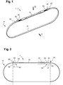
- the device 1 comprises a compensating member 10, two tightening loops 20 and 30, as well as two strands 40 and 50 connecting the member 10 to the loops 20 and 30.
- the device 1 is designed to cooperate with a strap 6, in order to secure an element 2 to a conduit 4.
- the strap 6 is elongated between two free ends 62 and 63 connected by a running part 61.
- the device 1 makes it possible to fix the strap 6 around the duct 4.
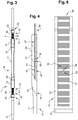
- the device 1 is shown at rest, without mechanical stresses exerted on its constituent elements.
- the device 1 and the strap 6 are shown in service, in the context of the securing of a support element 2 of cable 3 on a conduit 4.
- the element 2 is in one piece, formed from a single piece of plastic.
- the element 2 is stowed on the conduit 4 thanks to the device 1 and to the strap 6, in particular thanks to the passage of the strap 6 through an opening 8 made for this purpose in the element 2.
- element 2 can be of any other type suited to the intended application.
- the element 2 can support several cables 3.
- the element 2 can receive any other type of part, generally elongated, such as a sheath or a pipe.
- Cable 3 can be an electrical or digital data transfer cable.
- the conduit 4 is a metal tube, preferably covered with an insulating layer, for example made of polypropylene.
- the member 10 is in one piece, formed from a single piece of plastic material.
- the member 10 is made of polyurethane elastomer, as known under the trademark COURBHANE of the Applicant.
- the member 10 comprises a middle portion 11, two end portions 12 and 13, and two intermediate portions 14 and 15 formed between the middle portion 11 and the end portions 12 and 13, respectively.
- the member 10 has a lower surface 16 which extends over its entire length and is intended to bear against the external surface of the duct 4.
- the member 10 is symmetrical with respect to a transverse central plane.
- the portion 12 has dimensions identical to the portion 13, and the portion 14 has dimensions identical to the portion 15.
- the portion 11 In a longitudinal direction, the portion 11 is more elongated than the portions 12 and 13, which are themselves more elongated than the portions 14 and 15. In height and width, the portion 11 is less high and less wide than the portions 12 and 13. Thus, the portion 11 has a smaller cross section than the portions 12 and 13.
- the portions 14 and 15 have variable heights and widths. All the cross sections of portions 11-15 are parallelepiped.
- the tightening loops 20 and 30 are made of rigid material, not elastic under normal conditions of temperature and pressure (CNTP).
- the loops 20 and 30 can be made of metal or plastic, for example thermoplastic.
- the loop 20 comprises a base 21 secured to the strand 40 and an opening 22 provided to receive the end 62 of the strap 60.
- the loop 30 comprises a base 31 secured to the strand 50 and an opening 32 provided to receive the end 63 of strap 60.
- Each loop 20 and 30 is designed to allow a translation of the strap 60 through the opening 22 or 32 in the direction of the member 10, and to prevent a translation of the strap 60 in a direction opposite to the member 10. The strap 60 is thus tightened in the loops 20 and 30, which prevent it from relaxing.
- Each strand 40 and 50 is made of rigid material, not elastic under normal conditions of temperature and pressure (CNTP).
- the material of the strands 40 and 50 is chosen according to a compromise between strength and flexibility.
- the strands 40 and 50 can be made of plastic, metallic, composite, fabric or any other material suitable for the intended application.
- the loop 20 and the strand 40 constitute a single piece, and likewise the loop 30 and the strand 50 constitute a single piece.
- these parts are made of thermoplastic material.
- the strand 40 extends between two ends 41 and 42 connected by a running part 43.
- the strand 50 extends between two ends 51 and 52 connected by a running part 53.
- the ends 41 and 51 are integral with the member 10, more specifically portions 12 and 13, respectively.
- the ends 42 and 52 are integral with the loops 20 and 30, more precisely the bases 21 and 22, respectively.
- the ends 41 and 51 are secured to the member 10 by overmolding.
- the member 10 is molded onto the ends 41 and 51 of the strands 40 and 50.
- the ends 42 and 52 came integrally with the bases 21 and 31 of the loops 20 and 30, as mentioned above.
- the loops 20 and 30 can be secured to the strands 40 and 50 by any other means, for example overmolded on the ends 42 and 52.
- the end 51 has a smooth face 54 and a crenellated face 55.
- the face 55 has a relief formed by alternating slots 56 projecting and recesses 57 recessed between the slots 56.
- the recesses 57 receive the material from the member 10 during overmolding, which makes it possible to create a rigid connection between the member 10 and the strand 20.
- the end 51 may include other means for securing with the member 10.
- the end 51 may be provided with one or more orifices 58 passing through between the faces 56 and 57, which can be smooth or embossed. The material of the member 10 is then received in these orifices 58 during overmolding.
- Other securing means can be implemented without departing from the scope of the invention.
- end 51 also apply to end 41.
- the Figures 6 and 7 show the securing of element 2 to conduit 4, which initially has a diameter D4a.
- the strap 6 is first passed through the opening 8 formed in the element 2.
- the device 1 and the strap 6 are positioned around the conduit 4, then the ends 62 and 63 of the strap 6 are housed in the loops 20 and 30.
- the device 1 and the strap 6 are then tensioned around the duct 4, by tightening the strap 6 in the loops 20 and 30.
- the element 2 is thus pressed by the strap 6 against the duct 4.
- the tensile stresses exerted by the strands 40 and 50 on the portions 12 and 13 cause the elongation of the member 10.
- the member 10 has a length L10a greater than its length L10 at rest.
- the Figures 8 and 9 show the retraction of the conduit 4 over time. Its diameter D4a decreases to a diameter D4b. For example, after 25 years in immersion, the diameter D4b can reach 90% of the diameter D4a. Because of its elasticity properties, the member 10 gradually retracts while accompanying the retraction of the conduit 4. Thus the device 1 and the strap 6 remain held in tension, and the element 2 remains pressed against the conduit 4. L the member 10 then has a length L10b less than its initial length L10a, but greater than its length L10 at rest.
- the invention makes it possible to compensate for the loss of tension in the strap 6 due to the retraction of the conduit 4, and to keep the element 2 stowed on the conduit 4.
- the compensating member 10 makes it possible to provide flexibility and elasticity to the 1 + 6 lashing system, compared to a lashing system consisting only of a rigid strap.
- the device 1, the system 1 + 6 and the installation 1 + 2 + 3 + 4 + 6 can be shaped differently from the Figures 1 to 9 without departing from the scope of the invention, as defined by the claims.
- the technical characteristics of the different variants mentioned above can be, in whole or for some of them, combined.
- the device 1 can be adapted in terms of cost, functionalities and performance.
Abstract
La présente invention concerne un dispositif (1) pour arrimer un élément (2) sur un conduit (4), le dispositif (1) comprenant : un organe compensateur (10) en matériau élastique, extensible lorsque le dispositif (1) est mis sous tension autour du conduit (4) avec une sangle (6), et rétractable progressivement au cours du temps pour maintenir le dispositif (1) et la sangle (6) en tension lorsque le conduit (4) se rétracte ; deux boucles de serrage (20, 30) conçues pour recevoir chacune une extrémité libre (62, 63) de la sangle (6) ; et deux brins (40, 50) réalisés en matériau moins élastique que l'organe compensateur (10), et s'étendant chacun entre une première extrémité (41, 51) solidaire de l'organe compensateur (10) et une deuxième extrémité (42, 52) solidaire d'une des boucles de serrage (20, 30). L'invention concerne également un système (1, 6) comprenant un tel dispositif (1) et une sangle (6) ; une installation (1, 2, 3, 4, 6) comprenant un tel système (1, 6) ; et un procédé de mise en œuvre d'un tel système (1).The present invention relates to a device (1) for securing an element (2) on a conduit (4), the device (1) comprising: a compensating member (10) of elastic material, extensible when the device (1) is put under tension around the conduit (4) with a strap (6), and retractable gradually over time to keep the device (1) and the strap (6) in tension when the conduit (4) retracts; two tightening loops (20, 30) designed to each receive a free end (62, 63) of the strap (6); and two strands (40, 50) made of less elastic material than the compensating member (10), and each extending between a first end (41, 51) integral with the compensating member (10) and a second end ( 42, 52) secured to one of the tightening loops (20, 30). The invention also relates to a system (1, 6) comprising such a device (1) and a strap (6); an installation (1, 2, 3, 4, 6) comprising such a system (1, 6); and a method of implementing such a system (1).
Description
La présente invention concerne un dispositif de fixation d'une sangle, pour arrimer un élément sur un conduit. L'invention concerne également un système d'arrimage comprenant un tel dispositif et une sangle ; une installation comprenant un tel système ; et un procédé de mise en œuvre d'un tel système.The present invention relates to a device for fixing a strap, for securing an element on a duct. The invention also relates to a lashing system comprising such a device and a strap; an installation comprising such a system; and a method of implementing such a system.
Le domaine de l'invention est celui des conduits, tels que les pipelines sous-marins pour le transport d'hydrocarbures.The field of the invention is that of conduits, such as underwater pipelines for the transport of hydrocarbons.
Dans ce domaine, il est connu de fixer différents éléments le long des conduits, qui peuvent s'étendre sur plusieurs centaines de kilomètres, sur terre, sous terre et/ou sous l'eau. A titre d'exemples non limitatifs, ces éléments peuvent être des câbles électriques, des capteurs, ou des supports pour la fixation de câbles. Concernant ce dernier exemple, il est en effet préférable d'interposer un élément support entre le conduit et les câbles.In this field, it is known to fix different elements along the conduits, which can extend over several hundred kilometers, on land, underground and / or underwater. By way of nonlimiting examples, these elements can be electric cables, sensors, or supports for fixing cables. Regarding this last example, it is indeed preferable to interpose a support element between the conduit and the cables.
En pratique, l'élément arrimé sur le conduit doit rester en place pendant toute la durée de vie de ce conduit, par exemple 25 ans. L'élément immergé en profondeur doit résister aux pressions, aux variations de températures, aux courants, à la faune et à la flore marines, etc.In practice, the element secured to the duct must remain in place for the entire lifetime of this duct, for example 25 years. The submerged element must withstand pressure, temperature variations, currents, marine fauna and flora, etc.
De plus, il est remarquable que le conduit immergé se rétracte progressivement au cours du temps sous l'effet des contraintes auxquelles il est soumis, c'est-à-dire que son diamètre diminue progressivement. Si l'élément est arrimé sur le conduit à l'aide d'une sangle sous tension, alors la tension dans la sangle se relâche lorsque le conduit se rétracte, de sorte que l'élément n'est plus maintenu en place.In addition, it is remarkable that the submerged conduit gradually retracts over time under the effect of the stresses to which it is subjected, that is to say that its diameter gradually decreases. If the element is secured to the conduit using a tensioned strap, then the tension in the strap is released when the conduit is retracted, so that the element is no longer held in place.
Le document
Le document
Le but de la présente invention est de proposer un dispositif remédiant aux inconvénients ci-dessus.The object of the present invention is to provide a device which overcomes the above drawbacks.
A cet effet, l'invention a pour objet un dispositif pour l'arrimage d'un élément sur un conduit, le dispositif comprenant :
- un organe compensateur en matériau élastique, extensible lorsque le dispositif est mis sous tension autour du conduit avec une sangle, et rétractable progressivement au cours du temps pour maintenir le dispositif et la sangle en tension lorsque le conduit se rétracte ;
- deux boucles de serrage conçues pour recevoir chacune une extrémité libre de la sangle ; et
- deux brins réalisés en matériau moins élastique que l'organe compensateur, et s'étendant chacun entre une première extrémité solidaire de l'organe compensateur et une deuxième extrémité solidaire d'une des boucles de serrage.
- a compensating member of elastic material, extensible when the device is tensioned around the duct with a strap, and gradually retractable over time to keep the device and the strap in tension when the duct is retracted;
- two tightening loops each designed to receive a free end of the strap; and
- two strands made of less elastic material than the compensating member, and each extending between a first end secured to the compensating member and a second end secured to one of the tightening loops.
Le dispositif permet de compenser la perte de tension dans la sangle du fait de la rétractation du conduit, et maintenir l'élément arrimé sur le conduit. L'organe compensateur permet d'apporter de la souplesse et de l'élasticité au système d'arrimage constitué du dispositif et de la sangle, en comparaison avec un système constitué seulement d'une sangle.The device makes it possible to compensate for the loss of tension in the strap due to the retraction of the conduit, and to keep the element stowed on the conduit. The compensating member makes it possible to bring flexibility and elasticity to the securing system consisting of the device and the strap, in comparison with a system consisting only of a strap.
Les boucles de serrage permettent de recevoir et tendre la sangle de manière simple et pratique. La longueur de la sangle peut facilement être ajustée en fonction du périmètre du conduit. Ainsi, le dispositif peut être mis en œuvre pour toutes dimensions de conduits, avec une grande polyvalence.The tightening loops allow you to receive and tighten the strap in a simple and practical way. The length of the strap can easily be adjusted according to the perimeter of the conduit. Thus, the device can be implemented for all dimensions of conduits, with great versatility.
L'invention facilite l'arrimage d'un ou plusieurs éléments le long d'un conduit, sur une longueur importante, simplement avec un ensemble de dispositifs et un rouleau de sangle.The invention facilitates the securing of one or more elements along a duct, over a significant length, simply with a set of devices and a strap roller.
Selon d'autres caractéristiques avantageuses de l'invention, prises isolément ou en combinaison :
- Le dispositif est dépourvu de pièce métallique.
- L'organe compensateur est surmoulé sur les premières extrémités des brins.
- Les premières extrémités des brins comportent des évidements recevant de la matière de l'organe compensateur lors du surmoulage.
- Les évidements comprennent des creux formés en alternance entre des créneaux.
- Les évidements comprennent des orifices traversant entre deux faces opposées des brins.
- La première extrémité de chaque brin est solidaire directement de l'organe compensateur, sans pièce intermédiaire.
- La deuxième extrémité de chaque brin est solidaire directement d'une des boucles de serrage, sans pièce intermédiaire.
- La boucle de serrage et le brin associé constituent une même pièce.
- La boucle de serrage et le brin associé sont venus de matière.
- La boucle de serrage est surmoulée sur le brin associé.
- Le dispositif est uniquement constitué par l'organe compensateur, les deux boucles de serrage prévue pour recevoir la sangle, et les deux brins.
- Suivant une direction longitudinale du dispositif au repos, chacun des deux brins est plus court que l'organe compensateur.
- Le dispositif comprend un unique organe compensateur.
- L'organe compensateur est monobloc, formée d'une seule pièce en matériau plastique.
- L'organe compensateur comprend une portion médiane et deux portions d'extrémités recevant les premières extrémités des brins, les portions d'extrémités présentant des sections transversales plus grandes que la section transversale de la portion médiane.
- L'organe compensateur comprend des portions intermédiaires présentant des sections transversales variant progressivement entre la portion médiane et les portions d'extrémités.
- L'organe compensateur est en polyuréthane, de préférence en élastomère de polyuréthane.
- Les boucles de serrage sont en matière thermoplastique.
- Les brins sont en matière thermoplastique.
- The device has no metal part.
- The compensating member is overmolded on the first ends of the strands.
- The first ends of the strands have recesses receiving material from the compensating member during overmolding.
- The recesses include recesses formed alternately between slots.
- The recesses include orifices passing between two opposite faces of the strands.
- The first end of each strand is integral directly with the compensating member, without any intermediate piece.
- The second end of each strand is directly attached to one of the tightening loops, without any intermediate piece.
- The tightening loop and the associated strand constitute one piece.
- The tightening loop and the associated strand came in one piece.
- The tightening loop is overmolded on the associated strand.
- The device consists solely of the compensating member, the two tightening loops provided for receiving the strap, and the two strands.
- In a longitudinal direction of the device at rest, each of the two strands is shorter than the compensating member.
- The device comprises a single compensating member.
- The compensating member is in one piece, formed from a single piece of plastic material.
- The compensating member comprises a middle portion and two end portions receiving the first ends of the strands, the end portions having cross sections larger than the cross section of the middle portion.
- The compensating member comprises intermediate portions having cross sections varying progressively between the middle portion and the end portions.
- The compensating member is made of polyurethane, preferably of polyurethane elastomer.
- The tightening loops are made of thermoplastic material.
- The strands are made of thermoplastic material.
L'invention a également pour objet un système d'arrimage, comprenant : un dispositif tel que mentionné ci-dessus, et une sangle prévue pour coopérer avec le dispositif pour arrimer un élément à un conduit.The invention also relates to a securing system, comprising: a device as mentioned above, and a strap intended to cooperate with the device for securing an element to a conduit.
De préférence, le système comprend un ensemble de dispositifs et un rouleau de sangle. L'utilisateur peut ainsi arrimer facilement un ou plusieurs éléments le long du conduit, sur une longueur importante.Preferably, the system includes a set of devices and a strap roller. The user can thus easily stow one or more elements along the conduit, over a significant length.
L'invention a également pour objet une installation, comprenant : au moins un système d'arrimage tel que mentionné ci-dessus, au moins un élément prévu pour être arrimé à un conduit en mettant en œuvre le système, au moins une pièce fixée à l'élément, et le conduit supportant le système, l'élément et la pièce.The invention also relates to an installation, comprising: at least one securing system as mentioned above, at least one element designed to be secured to a duct by implementing the system, at least one part fixed to the element, and the conduit supporting the system, the element and the part.
L'invention a également pour objet un procédé de mise en œuvre d'un système d'arrimage tel que mentionné ci-dessus. Le procédé est caractérisé en ce qu'il comprend les étapes successives suivantes :
- a) assembler le système autour du conduit, en disposant les extrémités libres de la sangle dans les boucles de serrage du dispositif ;
- b) mettre sous tension le dispositif et la sangle autour du conduit, étirant ainsi l'organe compensateur ; puis
- c) lorsque le conduit se rétracte progressivement au cours du temps, l'organe compensateur se rétracte également, de sorte que le dispositif et la sangle sont maintenus en tension autour du conduit.
- a) assemble the system around the duct, placing the free ends of the strap in the tightening loops of the device;
- b) energize the device and the strap around the conduit, thereby stretching the compensating member; then
- c) when the conduit gradually retracts over time, the compensating member also retracts, so that the device and the strap are kept in tension around the conduit.
Selon un mode de réalisation particulier, le conduit est destiné à être immergé. Le système d'arrimage est submersible. L'organe compensateur est rétractable progressivement au cours du temps pour maintenir le dispositif et la sangle en tension lorsque le conduit se rétracte en immersion.According to a particular embodiment, the conduit is intended to be submerged. The stowage system is submersible. The compensating member is retractable gradually over time to keep the device and the strap in tension when the conduit retracts in immersion.
Selon un autre mode de réalisation particulier, le conduit est destiné à être enterré. L'organe compensateur est rétractable progressivement au cours du temps pour maintenir le dispositif et la sangle en tension lorsque le conduit se rétracte sous terre.According to another particular embodiment, the conduit is intended to be buried. The compensating member is retractable gradually over time to keep the device and the strap in tension when the conduit retracts underground.
L'invention sera mieux comprise à la lecture de la description qui va suivre, donnée uniquement à titre d'exemple non limitatif et faite en référence aux dessins annexés sur lesquels :
- La
figure 1 est une vue en perspective d'un système d'arrimage conforme à l'invention, comprenant un dispositif de fixation et une sangle. - La
figure 2 est une vue de face du système, selon la flèche II à lafigure 1 . - La
figure 3 est une vue de dessus du système, selon la flèche III à lafigure 1 . - La
figure 4 est une vue à plus grande échelle du détail IV de lafigure 2 . - La
figure 5 est une vue à plus grande échelle du détail V de lafigure 3 . - La
figure 6 est une vue de face d'une installation conforme à l'invention, comprenant le dispositif de fixation et la sangle constituant le système d'arrimage, un conduit cylindrique, un élément support arrimé au conduit, et un câble fixé à l'élément support. - La
figure 7 est une vue de côté selon la flèche VII de lafigure 6 . - La
figure 8 est une vue analogue à lafigure 6 , montrant le conduit et le dispositif qui se sont rétractés après plusieurs années de service. - La
figure 9 est une vue de côté selon la flèche IX de lafigure 8 .
- The
figure 1 is a perspective view of a securing system according to the invention, comprising a fixing device and a strap. - The
figure 2 is a front view of the system, according to arrow II at thefigure 1 . - The
figure 3 is a top view of the system, according to arrow III in thefigure 1 . - The
figure 4 is an enlarged view of detail IV of thefigure 2 . - The
figure 5 is an enlarged view of detail V of thefigure 3 . - The
figure 6 is a front view of an installation according to the invention, comprising the fixing device and the strap constituting the lashing system, a cylindrical conduit, a support element secured to the conduit, and a cable fixed to the support element . - The
figure 7 is a side view according to arrow VII of thefigure 6 . - The
figure 8 is a view analogous to thefigure 6 , showing the conduit and device that have retracted after several years of service. - The
figure 9 is a side view according to arrow IX of thefigure 8 .
Sur les
Le dispositif 1 est conçu pour coopérer avec une sangle 6, afin d'arrimer un élément 2 à un conduit 4. La sangle 6 est allongée entre deux extrémités libres 62 et 63 reliées par une partie courante 61. Le dispositif 1 permet de fixer la sangle 6 autour du conduit 4.The
Sur les
Sur les
L'élément 2 est monobloc, formé d'une seule pièce en matière plastique. L'élément 2 est arrimé sur le conduit 4 grâce au dispositif 1 et à la sangle 6, notamment grâce au passage de la sangle 6 à travers une ouverture 8 ménagée à cet effet dans l'élément 2.The
En alternative, l'élément 2 peut être de tout autre type adapté à l'application visée. Selon une variante, l'élément 2 peut supporter plusieurs câbles 3. Au lieu d'un câble 3, l'élément 2 peut recevoir tout autre type de pièce, généralement allongée, telle qu'une gaine ou un tuyau.Alternatively,
Le câble 3 peut être un câble électrique ou de transfert de données numériques.
Le conduit 4 est un tube de métal, de préférence recouvert d'une couche d'isolant, par exemple en polypropylène.The
L'organe 10 est monobloc, formé d'une seule pièce en matériau plastique. De préférence, l'organe 10 est en élastomère de polyuréthane, tel que connu sous la marque COURBHANE du Demandeur.The
L'organe 10 comprend une portion médiane 11, deux portions d'extrémités 12 et 13, et deux portions intermédiaires 14 et 15 formés entre la portion médiane 11 et les portions d'extrémités 12 et 13, respectivement. L'organe 10 comporte une surface inférieure 16 qui s'étend sur toute sa longueur et est destinée à venir en appui contre la surface externe du conduit 4.The
De préférence, l'organe 10 est symétrique par rapport à un plan central transversal. Ainsi, la portion 12 présente des dimensions identiques à la portion 13, et la portion 14 présente des dimensions identiques à la portion 15.Preferably, the
Suivant une direction longitudinale, la portion 11 est plus allongée que les portions 12 et 13, qui sont elles-mêmes plus allongées que les portions 14 et 15. En hauteur et en largeur, la portion 11 est moins haute et moins large que les portions 12 et 13. Ainsi, la portion 11 présente une section transversale plus petite que les portions 12 et 13. Les portions 14 et 15 présentent des hauteur et largeurs variables. Toutes les sections transversales des portions 11-15 sont parallélépipédiques.In a longitudinal direction, the
Du fait de ses dimensions inférieures et donc de sa résistance mécanique inférieure, c'est principalement la portion 11 qui est étirée lorsque l'organe 10 est soumis à des contraintes de traction sur ses deux portions d'extrémités 12 et 13.Because of its smaller dimensions and therefore of its lower mechanical strength, it is mainly the
Les boucles de serrage 20 et 30 sont en matériau rigide, non élastique dans les conditions normales de température et de pression (CNTP). Les boucles 20 et 30 peuvent être en métal ou en matière plastique, par exemple en matière thermoplastique.The tightening
La boucle 20 comprend une base 21 solidaire du brin 40 et une ouverture 22 prévue pour recevoir l'extrémité 62 de la sangle 60. La boucle 30 comprend une base 31 solidaire du brin 50 et une ouverture 32 prévue pour recevoir l'extrémité 63 de la sangle 60.The
Chaque boucle 20 et 30 est conçue pour autoriser une translation de la sangle 60 à travers l'ouverture 22 ou 32 en direction de l'organe 10, et pour empêcher une translation de la sangle 60 dans une direction opposée à l'organe 10. La sangle 60 est ainsi serrée dans les boucles 20 et 30, qui l'empêchent de se détendre.Each
Chaque brin 40 et 50 est en matériau rigide, non élastique dans les conditions normales de température et de pression (CNTP). Le matériau des brins 40 et 50 est choisi selon un compromis entre résistance et souplesse. Les brins 40 et 50 peuvent être en matériau plastique, métallique, composite, tissu ou toute autre matière adaptée à l'application visée.Each
Selon un mode de réalisation préféré, la boucle 20 et le brin 40 constituent une unique pièce, et de même la boucle 30 et le brin 50 constituent une unique pièce. Par exemple, ces pièces sont en matière thermoplastique.According to a preferred embodiment, the
Le brin 40 s'étend entre deux extrémités 41 et 42 reliées par une partie courante 43. De même, le brin 50 s'étend entre deux extrémités 51 et 52 reliées par une partie courante 53. Les extrémités 41 et 51 sont solidaires de l'organe 10, plus précisément des portions 12 et 13, respectivement. Les extrémités 42 et 52 sont solidaires des boucles 20 et 30, plus précisément des base 21 et 22, respectivement.The
De préférence, les extrémités 41 et 51 sont solidarisées à l'organe 10 par surmoulage. Autrement dit, l'organe 10 est surmoulé sur les extrémités 41 et 51 des brins 40 et 50.Preferably, the ends 41 and 51 are secured to the
Egalement de préférence, les extrémités 42 et 52 sont venues de matière avec les bases 21 et 31 des boucles 20 et 30, comme mentionné plus haut. En alternative, les boucles 20 et 30 peuvent être solidarisées aux brins 40 et 50 par tout autre moyen, par exemple surmoulées sur les extrémités 42 et 52.Also preferably, the ends 42 and 52 came integrally with the
Comme montré aux
En alternative ou en complément, l'extrémité 51 peut comporter d'autres moyens de solidarisation avec l'organe 10. Par exemple, l'extrémité 51 peut être munie d'un ou plusieurs orifices 58 traversant entre les faces 56 et 57, lesquelles peuvent être lisses ou en relief. La matière de l'organe 10 est alors reçue dans ces orifices 58 lors du surmoulage. D'autres moyens de solidarisation peuvent être mis en œuvre sans sortir du cadre de l'invention.As an alternative or in addition, the
Les explications données ci-dessus pour l'extrémité 51 sont également valable pour l'extrémité 41.The explanations given above for
Les
Les
Ainsi, l'invention permet de compenser la perte de tension dans la sangle 6 du fait de la rétractation du conduit 4, et maintenir l'élément 2 arrimé sur le conduit 4. L'organe compensateur 10 permet d'apporter de la souplesse et de l'élasticité au système d'arrimage 1+6, en comparaison avec une système d'arrimage constitué seulement d'une sangle rigide.Thus, the invention makes it possible to compensate for the loss of tension in the
Par ailleurs, le dispositif 1, le système 1+6 et l'installation 1+2+3+4+6 peuvent être conformés différemment des
Claims (10)
Applications Claiming Priority (1)
| Application Number | Priority Date | Filing Date | Title |
|---|---|---|---|
| FR1873856A FR3090762B1 (en) | 2018-12-21 | 2018-12-21 | Device for securing an element on a duct, securing system, installation and implementation method |
Publications (2)
| Publication Number | Publication Date |
|---|---|
| EP3674590A1 true EP3674590A1 (en) | 2020-07-01 |
| EP3674590B1 EP3674590B1 (en) | 2023-02-01 |
Family
ID=66690565
Family Applications (1)
| Application Number | Title | Priority Date | Filing Date |
|---|---|---|---|
| EP19213990.5A Active EP3674590B1 (en) | 2018-12-21 | 2019-12-05 | Device for securing a member to a pipe, system for securing, installation and method for implementing same |
Country Status (4)
| Country | Link |
|---|---|
| US (1) | US11326719B2 (en) |
| EP (1) | EP3674590B1 (en) |
| BR (1) | BR102019027234A2 (en) |
| FR (1) | FR3090762B1 (en) |
Families Citing this family (1)
| Publication number | Priority date | Publication date | Assignee | Title |
|---|---|---|---|---|
| EP4155227A1 (en) | 2021-09-24 | 2023-03-29 | Nexans | Cable tie, fixing set and method for mounting the cable tie |
Citations (5)
| Publication number | Priority date | Publication date | Assignee | Title |
|---|---|---|---|---|
| US20040237264A1 (en) * | 2001-08-01 | 2004-12-02 | Shaw Stephen James | Securing strap arrangement and tensioner therefor |
| DE102004053863A1 (en) * | 2004-11-04 | 2006-05-11 | Ludwig Michelbach | Object e.g. cable, bundling/winding/holding mechanism, has blocking device cooperating with profile of strip so that respective strip ends are inserted in bushing in forward direction, and strip is not retractable in reverse direction |
| EP1965116A1 (en) * | 2007-03-02 | 2008-09-03 | Fiat Group Automobiles S.p.A. | Collar for the support and retention of objects, in particular for the support and retention of combustible gas tanks |
| FR2965252A1 (en) | 2010-09-24 | 2012-03-30 | Pms Internat | Device for partial loss compensation of inherent stretching tension of woven belt in load stowing system, has accumulator constituted by elongate element, whose dimensional characteristics of component materials are elastically deformable |
| FR3059059A1 (en) | 2016-11-23 | 2018-05-25 | Financiere De Beaumont - Fdb | DEVICE FOR ARRANGING AN ELEMENT ON A DUCT FOR IMMERING, SUBMERSIBLE ASSEMBLY, INSTALLATION AND METHOD FOR IMPLEMENTING THE SAME |
Family Cites Families (10)
| Publication number | Priority date | Publication date | Assignee | Title |
|---|---|---|---|---|
| US3086369A (en) * | 1961-10-02 | 1963-04-23 | Aluminum Co Of America | Underwater pipe line and method |
| DE2813484C2 (en) * | 1978-03-29 | 1982-12-30 | United-Carr Gmbh, 6000 Frankfurt | Cable tie |
| US5040751A (en) * | 1985-12-31 | 1991-08-20 | Holub Sidney L | Adjustable pipe hanger |
| US6330989B1 (en) * | 1999-04-15 | 2001-12-18 | Shimano Inc. | Conduit guide for bicycles |
| US6138327A (en) * | 1999-08-31 | 2000-10-31 | Powell; Andrew P. | Flexible strap arrangement |
| GB2413358A (en) * | 2004-04-20 | 2005-10-26 | Performance Oil Tools Ltd | Cable clamp with flexible fastening member |
| US7866005B2 (en) * | 2008-01-09 | 2011-01-11 | Panduit Corp. | Elastomeric releasable cable tie |
| US8510918B2 (en) * | 2009-02-23 | 2013-08-20 | Avery Dennison Corporation | Cable tie |
| US8186643B2 (en) * | 2010-03-25 | 2012-05-29 | General Electric Company | Apparatus for attaching a device to a circular structure |
| US9512941B2 (en) * | 2013-07-23 | 2016-12-06 | Hawken Holdings, Llc | Conduit guide apparatus, system, and method |
-
2018
- 2018-12-21 FR FR1873856A patent/FR3090762B1/en active Active
-
2019
- 2019-12-05 EP EP19213990.5A patent/EP3674590B1/en active Active
- 2019-12-17 US US16/716,522 patent/US11326719B2/en active Active
- 2019-12-19 BR BR102019027234-1A patent/BR102019027234A2/en unknown
Patent Citations (5)
| Publication number | Priority date | Publication date | Assignee | Title |
|---|---|---|---|---|
| US20040237264A1 (en) * | 2001-08-01 | 2004-12-02 | Shaw Stephen James | Securing strap arrangement and tensioner therefor |
| DE102004053863A1 (en) * | 2004-11-04 | 2006-05-11 | Ludwig Michelbach | Object e.g. cable, bundling/winding/holding mechanism, has blocking device cooperating with profile of strip so that respective strip ends are inserted in bushing in forward direction, and strip is not retractable in reverse direction |
| EP1965116A1 (en) * | 2007-03-02 | 2008-09-03 | Fiat Group Automobiles S.p.A. | Collar for the support and retention of objects, in particular for the support and retention of combustible gas tanks |
| FR2965252A1 (en) | 2010-09-24 | 2012-03-30 | Pms Internat | Device for partial loss compensation of inherent stretching tension of woven belt in load stowing system, has accumulator constituted by elongate element, whose dimensional characteristics of component materials are elastically deformable |
| FR3059059A1 (en) | 2016-11-23 | 2018-05-25 | Financiere De Beaumont - Fdb | DEVICE FOR ARRANGING AN ELEMENT ON A DUCT FOR IMMERING, SUBMERSIBLE ASSEMBLY, INSTALLATION AND METHOD FOR IMPLEMENTING THE SAME |
Also Published As
| Publication number | Publication date |
|---|---|
| US20200224797A1 (en) | 2020-07-16 |
| US11326719B2 (en) | 2022-05-10 |
| FR3090762B1 (en) | 2021-03-05 |
| BR102019027234A2 (en) | 2020-07-14 |
| EP3674590B1 (en) | 2023-02-01 |
| FR3090762A1 (en) | 2020-06-26 |
Similar Documents
| Publication | Publication Date | Title |
|---|---|---|
| EP1284324B1 (en) | Device and process for fastening a building element and a cable structure and suspension bridge having such devices | |
| EP3327297B1 (en) | Device for securing a member to a pipe, implementation assembly, installation and method | |
| EP3674590B1 (en) | Device for securing a member to a pipe, system for securing, installation and method for implementing same | |
| FR2507972A1 (en) | DEVICE FOR INCREASING THE TENSION FORCES EXERCISED BY THE TIRES OF VEHICLES | |
| FR2459896A1 (en) | HOLDING DEVICE FOR FASTENING OBJECTS AND WIREHOLE ASSEMBLY FOR AERONAUTICS | |
| WO2014114869A2 (en) | Device for securing and retaining at least one electrical harness in a turbomachine | |
| EP3035098B1 (en) | Branching device for an optical cable | |
| FR2519305A1 (en) | Luggage rack for vehicle roof - comprises carriers which receive luggage and releasably engage support | |
| EP2795611B1 (en) | Acoustic antenna element for emitting and/or receiving waves under water and associated acoustic antenna | |
| EP0030180A1 (en) | Joining device for pipes | |
| WO2006061513A1 (en) | Device for fixing a floating element to a conduit | |
| FR2789815A1 (en) | Anchor clamp for isolated multi-conductor cable containing optic fibres | |
| FR2633462A1 (en) | DEVICE FOR JOINING ARMORIES OF TWO CABLES ARMED BY WIRES, AND METHOD FOR MANUFACTURING THE SAME | |
| EP0437639B1 (en) | Seal for the connection of two parts of a conveyor belt and connection comprising such a seal | |
| FR2803762A1 (en) | METHOD FOR MANUFACTURING AN ANTI-WEAR FASTENING DEVICE FOR A SHORTS OR A ROPE BAG, AND STRAP FASTENER OBTAINED ACCORDING TO THE METHOD | |
| EP3822530B1 (en) | Aircraft comprising at least one connection device connecting an electrical cable and a conduit to a support | |
| FR2866908A1 (en) | Surface cover for vehicle, has consecutive plates articulated with each other by connection unit having ends which are connected to plates, where connection unit has section which is formed of two circles connected by bridging | |
| EP0797281A1 (en) | Process and assembly for mounting tightly a resilient tubular covering on an element | |
| FR2723487A1 (en) | Longitudinal axis modular fastener for telecommunications optical fibre cable | |
| EP3563067A1 (en) | Banding device | |
| FR2649385A1 (en) | Means of anchoring a tank on a concrete bed | |
| FR3029023A1 (en) | ANCHOR DEVICE FOR ANCHORING PREDETERMINED DIAMETER CABLE TO A SUPPORT | |
| EP4311449A1 (en) | Strap adjustment system | |
| FR2760144A1 (en) | Terminating grip for lightweight overhead cables such as optical fibres | |
| FR3051530A1 (en) | SYSTEM FOR MAINTAINING A CENTERING AND PROTECTIVE TIP ON A SHEET FOR THE INSTALLATION OF AN INTERIOR TUBE |
Legal Events
| Date | Code | Title | Description |
|---|---|---|---|
| PUAI | Public reference made under article 153(3) epc to a published international application that has entered the european phase |
Free format text: ORIGINAL CODE: 0009012 |
|
| STAA | Information on the status of an ep patent application or granted ep patent |
Free format text: STATUS: THE APPLICATION HAS BEEN PUBLISHED |
|
| AK | Designated contracting states |
Kind code of ref document: A1 Designated state(s): AL AT BE BG CH CY CZ DE DK EE ES FI FR GB GR HR HU IE IS IT LI LT LU LV MC MK MT NL NO PL PT RO RS SE SI SK SM TR |
|
| AX | Request for extension of the european patent |
Extension state: BA ME |
|
| STAA | Information on the status of an ep patent application or granted ep patent |
Free format text: STATUS: REQUEST FOR EXAMINATION WAS MADE |
|
| 17P | Request for examination filed |
Effective date: 20201113 |
|
| RBV | Designated contracting states (corrected) |
Designated state(s): AL AT BE BG CH CY CZ DE DK EE ES FI FR GB GR HR HU IE IS IT LI LT LU LV MC MK MT NL NO PL PT RO RS SE SI SK SM TR |
|
| STAA | Information on the status of an ep patent application or granted ep patent |
Free format text: STATUS: EXAMINATION IS IN PROGRESS |
|
| 17Q | First examination report despatched |
Effective date: 20220413 |
|
| GRAP | Despatch of communication of intention to grant a patent |
Free format text: ORIGINAL CODE: EPIDOSNIGR1 |
|
| STAA | Information on the status of an ep patent application or granted ep patent |
Free format text: STATUS: GRANT OF PATENT IS INTENDED |
|
| RIC1 | Information provided on ipc code assigned before grant |
Ipc: F16B 7/04 20060101ALN20220929BHEP Ipc: F16B 2/08 20060101ALN20220929BHEP Ipc: F16L 3/233 20060101ALI20220929BHEP Ipc: F16L 1/20 20060101AFI20220929BHEP |
|
| RIC1 | Information provided on ipc code assigned before grant |
Ipc: F16B 7/04 20060101ALN20221004BHEP Ipc: F16B 2/08 20060101ALN20221004BHEP Ipc: F16L 3/233 20060101ALI20221004BHEP Ipc: F16L 1/20 20060101AFI20221004BHEP |
|
| INTG | Intention to grant announced |
Effective date: 20221020 |
|
| GRAS | Grant fee paid |
Free format text: ORIGINAL CODE: EPIDOSNIGR3 |
|
| GRAA | (expected) grant |
Free format text: ORIGINAL CODE: 0009210 |
|
| STAA | Information on the status of an ep patent application or granted ep patent |
Free format text: STATUS: THE PATENT HAS BEEN GRANTED |
|
| AK | Designated contracting states |
Kind code of ref document: B1 Designated state(s): AL AT BE BG CH CY CZ DE DK EE ES FI FR GB GR HR HU IE IS IT LI LT LU LV MC MK MT NL NO PL PT RO RS SE SI SK SM TR |
|
| REG | Reference to a national code |
Ref country code: GB Ref legal event code: FG4D Free format text: NOT ENGLISH |
|
| REG | Reference to a national code |
Ref country code: NL Ref legal event code: FP |
|
| REG | Reference to a national code |
Ref country code: CH Ref legal event code: EP Ref country code: AT Ref legal event code: REF Ref document number: 1547022 Country of ref document: AT Kind code of ref document: T Effective date: 20230215 |
|
| REG | Reference to a national code |
Ref country code: DE Ref legal event code: R096 Ref document number: 602019024997 Country of ref document: DE |
|
| REG | Reference to a national code |
Ref country code: IE Ref legal event code: FG4D Free format text: LANGUAGE OF EP DOCUMENT: FRENCH |
|
| REG | Reference to a national code |
Ref country code: NO Ref legal event code: T2 Effective date: 20230201 |
|
| REG | Reference to a national code |
Ref country code: LT Ref legal event code: MG9D |
|
| REG | Reference to a national code |
Ref country code: AT Ref legal event code: MK05 Ref document number: 1547022 Country of ref document: AT Kind code of ref document: T Effective date: 20230201 |
|
| PG25 | Lapsed in a contracting state [announced via postgrant information from national office to epo] |
Ref country code: RS Free format text: LAPSE BECAUSE OF FAILURE TO SUBMIT A TRANSLATION OF THE DESCRIPTION OR TO PAY THE FEE WITHIN THE PRESCRIBED TIME-LIMIT Effective date: 20230201 Ref country code: PT Free format text: LAPSE BECAUSE OF FAILURE TO SUBMIT A TRANSLATION OF THE DESCRIPTION OR TO PAY THE FEE WITHIN THE PRESCRIBED TIME-LIMIT Effective date: 20230601 Ref country code: LV Free format text: LAPSE BECAUSE OF FAILURE TO SUBMIT A TRANSLATION OF THE DESCRIPTION OR TO PAY THE FEE WITHIN THE PRESCRIBED TIME-LIMIT Effective date: 20230201 Ref country code: LT Free format text: LAPSE BECAUSE OF FAILURE TO SUBMIT A TRANSLATION OF THE DESCRIPTION OR TO PAY THE FEE WITHIN THE PRESCRIBED TIME-LIMIT Effective date: 20230201 Ref country code: HR Free format text: LAPSE BECAUSE OF FAILURE TO SUBMIT A TRANSLATION OF THE DESCRIPTION OR TO PAY THE FEE WITHIN THE PRESCRIBED TIME-LIMIT Effective date: 20230201 Ref country code: ES Free format text: LAPSE BECAUSE OF FAILURE TO SUBMIT A TRANSLATION OF THE DESCRIPTION OR TO PAY THE FEE WITHIN THE PRESCRIBED TIME-LIMIT Effective date: 20230201 Ref country code: AT Free format text: LAPSE BECAUSE OF FAILURE TO SUBMIT A TRANSLATION OF THE DESCRIPTION OR TO PAY THE FEE WITHIN THE PRESCRIBED TIME-LIMIT Effective date: 20230201 |
|
| PG25 | Lapsed in a contracting state [announced via postgrant information from national office to epo] |
Ref country code: SE Free format text: LAPSE BECAUSE OF FAILURE TO SUBMIT A TRANSLATION OF THE DESCRIPTION OR TO PAY THE FEE WITHIN THE PRESCRIBED TIME-LIMIT Effective date: 20230201 Ref country code: PL Free format text: LAPSE BECAUSE OF FAILURE TO SUBMIT A TRANSLATION OF THE DESCRIPTION OR TO PAY THE FEE WITHIN THE PRESCRIBED TIME-LIMIT Effective date: 20230201 Ref country code: IS Free format text: LAPSE BECAUSE OF FAILURE TO SUBMIT A TRANSLATION OF THE DESCRIPTION OR TO PAY THE FEE WITHIN THE PRESCRIBED TIME-LIMIT Effective date: 20230601 Ref country code: GR Free format text: LAPSE BECAUSE OF FAILURE TO SUBMIT A TRANSLATION OF THE DESCRIPTION OR TO PAY THE FEE WITHIN THE PRESCRIBED TIME-LIMIT Effective date: 20230502 Ref country code: FI Free format text: LAPSE BECAUSE OF FAILURE TO SUBMIT A TRANSLATION OF THE DESCRIPTION OR TO PAY THE FEE WITHIN THE PRESCRIBED TIME-LIMIT Effective date: 20230201 |
|
| PG25 | Lapsed in a contracting state [announced via postgrant information from national office to epo] |
Ref country code: SM Free format text: LAPSE BECAUSE OF FAILURE TO SUBMIT A TRANSLATION OF THE DESCRIPTION OR TO PAY THE FEE WITHIN THE PRESCRIBED TIME-LIMIT Effective date: 20230201 Ref country code: RO Free format text: LAPSE BECAUSE OF FAILURE TO SUBMIT A TRANSLATION OF THE DESCRIPTION OR TO PAY THE FEE WITHIN THE PRESCRIBED TIME-LIMIT Effective date: 20230201 Ref country code: EE Free format text: LAPSE BECAUSE OF FAILURE TO SUBMIT A TRANSLATION OF THE DESCRIPTION OR TO PAY THE FEE WITHIN THE PRESCRIBED TIME-LIMIT Effective date: 20230201 Ref country code: DK Free format text: LAPSE BECAUSE OF FAILURE TO SUBMIT A TRANSLATION OF THE DESCRIPTION OR TO PAY THE FEE WITHIN THE PRESCRIBED TIME-LIMIT Effective date: 20230201 Ref country code: CZ Free format text: LAPSE BECAUSE OF FAILURE TO SUBMIT A TRANSLATION OF THE DESCRIPTION OR TO PAY THE FEE WITHIN THE PRESCRIBED TIME-LIMIT Effective date: 20230201 |
|
| REG | Reference to a national code |
Ref country code: DE Ref legal event code: R097 Ref document number: 602019024997 Country of ref document: DE |
|
| PG25 | Lapsed in a contracting state [announced via postgrant information from national office to epo] |
Ref country code: SK Free format text: LAPSE BECAUSE OF FAILURE TO SUBMIT A TRANSLATION OF THE DESCRIPTION OR TO PAY THE FEE WITHIN THE PRESCRIBED TIME-LIMIT Effective date: 20230201 |
|
| PLBE | No opposition filed within time limit |
Free format text: ORIGINAL CODE: 0009261 |
|
| STAA | Information on the status of an ep patent application or granted ep patent |
Free format text: STATUS: NO OPPOSITION FILED WITHIN TIME LIMIT |
|
| PGFP | Annual fee paid to national office [announced via postgrant information from national office to epo] |
Ref country code: NL Payment date: 20231124 Year of fee payment: 5 |
|
| 26N | No opposition filed |
Effective date: 20231103 |
|
| PGFP | Annual fee paid to national office [announced via postgrant information from national office to epo] |
Ref country code: GB Payment date: 20231221 Year of fee payment: 5 |
|
| PGFP | Annual fee paid to national office [announced via postgrant information from national office to epo] |
Ref country code: MC Payment date: 20231121 Year of fee payment: 5 |
|
| PG25 | Lapsed in a contracting state [announced via postgrant information from national office to epo] |
Ref country code: SI Free format text: LAPSE BECAUSE OF FAILURE TO SUBMIT A TRANSLATION OF THE DESCRIPTION OR TO PAY THE FEE WITHIN THE PRESCRIBED TIME-LIMIT Effective date: 20230201 |
|
| PGFP | Annual fee paid to national office [announced via postgrant information from national office to epo] |
Ref country code: NO Payment date: 20231128 Year of fee payment: 5 Ref country code: IT Payment date: 20231211 Year of fee payment: 5 Ref country code: FR Payment date: 20231226 Year of fee payment: 5 |