EP2411717B1 - Schutzhülse für ein flexibles rohr - Google Patents
Schutzhülse für ein flexibles rohr Download PDFInfo
- Publication number
- EP2411717B1 EP2411717B1 EP10716568.0A EP10716568A EP2411717B1 EP 2411717 B1 EP2411717 B1 EP 2411717B1 EP 10716568 A EP10716568 A EP 10716568A EP 2411717 B1 EP2411717 B1 EP 2411717B1
- Authority
- EP
- European Patent Office
- Prior art keywords
- rings
- protective sleeve
- opposite
- longitudinal portion
- tapered member
- Prior art date
- Legal status (The legal status is an assumption and is not a legal conclusion. Google has not performed a legal analysis and makes no representation as to the accuracy of the status listed.)
- Active
Links
- 230000001681 protective effect Effects 0.000 title claims description 36
- 229930195733 hydrocarbon Natural products 0.000 claims description 4
- 150000002430 hydrocarbons Chemical class 0.000 claims description 4
- 230000008602 contraction Effects 0.000 claims description 3
- 230000006835 compression Effects 0.000 claims description 2
- 238000007906 compression Methods 0.000 claims description 2
- 239000002861 polymer material Substances 0.000 claims description 2
- 238000005452 bending Methods 0.000 description 12
- 239000004814 polyurethane Substances 0.000 description 5
- 238000009434 installation Methods 0.000 description 3
- 239000000463 material Substances 0.000 description 3
- 239000002184 metal Substances 0.000 description 3
- 229920002635 polyurethane Polymers 0.000 description 3
- 239000003351 stiffener Substances 0.000 description 3
- 230000000903 blocking effect Effects 0.000 description 2
- 239000000470 constituent Substances 0.000 description 2
- 238000000034 method Methods 0.000 description 2
- 229910000831 Steel Inorganic materials 0.000 description 1
- 230000003042 antagnostic effect Effects 0.000 description 1
- 230000000694 effects Effects 0.000 description 1
- 229920001971 elastomer Polymers 0.000 description 1
- 239000000806 elastomer Substances 0.000 description 1
- 239000000835 fiber Substances 0.000 description 1
- 239000012530 fluid Substances 0.000 description 1
- 239000007789 gas Substances 0.000 description 1
- 230000002427 irreversible effect Effects 0.000 description 1
- 239000003949 liquefied natural gas Substances 0.000 description 1
- 238000000465 moulding Methods 0.000 description 1
- 230000007935 neutral effect Effects 0.000 description 1
- 239000003208 petroleum Substances 0.000 description 1
- 239000004033 plastic Substances 0.000 description 1
- 229920003023 plastic Polymers 0.000 description 1
- 238000007665 sagging Methods 0.000 description 1
- 239000010959 steel Substances 0.000 description 1
- XLYOFNOQVPJJNP-UHFFFAOYSA-N water Substances O XLYOFNOQVPJJNP-UHFFFAOYSA-N 0.000 description 1
- 238000003466 welding Methods 0.000 description 1
Images

Classifications
-
- F—MECHANICAL ENGINEERING; LIGHTING; HEATING; WEAPONS; BLASTING
- F16—ENGINEERING ELEMENTS AND UNITS; GENERAL MEASURES FOR PRODUCING AND MAINTAINING EFFECTIVE FUNCTIONING OF MACHINES OR INSTALLATIONS; THERMAL INSULATION IN GENERAL
- F16L—PIPES; JOINTS OR FITTINGS FOR PIPES; SUPPORTS FOR PIPES, CABLES OR PROTECTIVE TUBING; MEANS FOR THERMAL INSULATION IN GENERAL
- F16L35/00—Special arrangements used in connection with end fittings of hoses, e.g. safety or protecting devices
-
- F—MECHANICAL ENGINEERING; LIGHTING; HEATING; WEAPONS; BLASTING
- F16—ENGINEERING ELEMENTS AND UNITS; GENERAL MEASURES FOR PRODUCING AND MAINTAINING EFFECTIVE FUNCTIONING OF MACHINES OR INSTALLATIONS; THERMAL INSULATION IN GENERAL
- F16L—PIPES; JOINTS OR FITTINGS FOR PIPES; SUPPORTS FOR PIPES, CABLES OR PROTECTIVE TUBING; MEANS FOR THERMAL INSULATION IN GENERAL
- F16L1/00—Laying or reclaiming pipes; Repairing or joining pipes on or under water
- F16L1/12—Laying or reclaiming pipes on or under water
- F16L1/123—Devices for the protection of pipes under water
-
- F—MECHANICAL ENGINEERING; LIGHTING; HEATING; WEAPONS; BLASTING
- F16—ENGINEERING ELEMENTS AND UNITS; GENERAL MEASURES FOR PRODUCING AND MAINTAINING EFFECTIVE FUNCTIONING OF MACHINES OR INSTALLATIONS; THERMAL INSULATION IN GENERAL
- F16L—PIPES; JOINTS OR FITTINGS FOR PIPES; SUPPORTS FOR PIPES, CABLES OR PROTECTIVE TUBING; MEANS FOR THERMAL INSULATION IN GENERAL
- F16L57/00—Protection of pipes or objects of similar shape against external or internal damage or wear
- F16L57/02—Protection of pipes or objects of similar shape against external or internal damage or wear against cracking or buckling
Definitions
- the present invention relates to protective sleeves intended to preserve the flexible pipes used for the transport of fluids such as hydrocarbons and especially gas, between offshore installations.
- the invention relates to a stiffening sleeve intended to be mounted around a longitudinal portion of flexible pipe, usually near a pipe end, to withstand the bending of said longitudinal portion in any desired curvature. to preserve it from irreversible damage. Damage may result either from excessive bending of the flexible pipe portion at a small radius of curvature or from the repetition of bending, caused by wave or water currents.
- Stiffening sleeves known and widely used in the field of flexible oil pipes consist of a conical body molded in a plastic material, usually polyurethane. These stiffening sleeves or " bend stiffener " in English, are then mounted around the flexible pipe before installation of the nozzle. They have a relatively large mass of several hundred kg, for example 900 kg. Also, the handling and installation of this type of sleeve are relatively uncomfortable. In addition, they are made of a single piece of a polymeric material whose cost is relatively high and which requires a suitable molding technique. Another disadvantage is that of replacing this type of stiffening sleeve which can not be done without cutting the section of flexible pipe that carries it.
- the document W02006 / 033579 discloses such a stiffener sleeve for a flexible pipe for transporting hydrocarbons.
- the elastic properties of the metal rods and their spacings around the perimeter of the flexible pipe portion define the stiffness of the sleeve and therefore the flexural strength experienced by the flexible pipe portion.
- a problem that arises and that aims to solve the present invention is to provide a protective sleeve that not only allows to withstand the flexion of the flexible pipe, but beyond, which allows to prohibit sagging below a limited radius of curvature.
- the present invention proposes a protective sleeve adapted to be installed around a longitudinal portion of flexible pipe for the transport of hydrocarbons, to resist bending of said longitudinal portion of any curvature.
- Said sleeve comprises a set of rings each having two opposite flanks, the rings of said assembly being successively held together coaxially and the flanks respectively opposite by a plurality of elastically deformable axial connecting elements distributed circularly between the flanks of said rings. The bending of said longitudinal portion is then able to cause the contraction of the connecting elements located towards the inside of the curvature and simultaneously, the elongation of the opposite connecting elements situated towards the outside of the curvature to resist bending of said longitudinal portion of flexible pipe.
- each connecting element has two opposite rigid fixing parts and a deformable elastic body interposed between said two fixing parts to allow the relative movement of said two fixing parts by generating return forces on said fixing parts; and said attachment portions of each link member are respectively fixed in the flanks facing said rings, so that the flexion of said longitudinal pipe portion is able to cause compression of said deformable elastic body of the axial connecting elements of the inside of the curvature and the traction of the axial connecting elements of outside the curvature to transmit the recall forces to said rings.
- an advantageous feature of the invention lies in the implementation of three-part connecting elements, two rigid attachment parts, located at the two opposite ends of said connecting element, and a portion consisting of a deformable elastic body. , for example of polymer material, interposed between said two rigid parts.
- a deformable elastic body for example of polymer material
- the pipe for certain applications, for example when the flexible pipe carries liquefied natural gas, and for which high stresses tending to cause its flexion are exerted, it is advantageous to provide the pipe with a protective sleeve conforming to the invention, which limits the radius of curvature of the flexible pipe portion on which it is fitted to a minimum value.
- Such a protective sleeve is relatively inexpensive and also lighter than conventional polyurethane conical stiffening sleeves. It consists for example of modules comprising a specific number of rings, then assembled, which makes it easier, its mounting on the pipe and the replacement of one of its modules compared to the solutions of the prior art.
- said flanks of each ring have a circular rim inner ring located towards the center of said ring and which extends substantially perpendicular to said flank, and said rings of said set of rings are kept close together so that the flexion of said longitudinal portion is able to cause, in addition, the contacting respectively the inner circular flange portions of said rings located inwardly of the curvature to block bending of said longitudinal pipe portion.
- the contacting of the inner circular flange portions allows mechanical locking of the rings towards the inside of the curvature and prohibits the bending of the pipe portion beyond a certain limit and within a radius limit curvature.
- the control of the curvature of the portion of pipe engaged inside is double.
- the bending resistance of the protective sleeve and the limitation of its curvature already makes it possible, thanks to the connecting elements, to preserve the pipe portion of an excessive curvature and, moreover, the particular shape of the rings allows their contact and blocking. bending of the sleeve and consequently of the pipe.
- flanks of said rings have an outer circular edge located opposite the center of said ring relative to said inner circular flange, and said fastening portions of each connecting element are respectively fixed in said outer circular edges.
- said rings are respectively formed of two concentric rings embedded one inside the other. One of them, the inner ring is wider and is embedded in the other to be fully integral to form the ring.
- said connecting elements consist of silentblocs and said two opposite rigid attachment parts comprise firstly, a receiving sleeve having a bottom and an opening and secondly, a substantially frustoconical member adapted to be engaged. at through said opening so that the tip of said frustoconical member is oriented towards said bottom, while said deformable elastic body comprises a hollow cylindrical member adapted to be engaged within said sleeve and to receive said frustoconical member.
- this hollow cylindrical PU member is bonded to the inside of the sleeve, while the frustoconical member is bonded to it inside the hollow cylindrical member.
- the method of bonding, steel to PU is sufficiently strong to withstand a deformation in tension of the hollow cylindrical member, when the sleeve and the frustoconical member are spaced apart from each other, without causing disconnection of the three elements.
- said receiving sleeve has a socket rod integral with said bottom and which extends outside said socket and opposite said opening, said socket rod being intended to be engaged through said rings in an axial direction to secure said sleeve to said rings.
- said bushing rod passes through said ring from one side to the other and its free end is threaded to receive a nut that bears against the flank opposite to that which receives the socket in support.
- said frustoconical member advantageously has a frustoconical member rod integral with said frustoconical member and which extends opposite said tip, said frustoconical member rod being intended to be engaged through said rings in a manner axial direction for securing said frustoconical member to said rings.
- the rings of said set are each advantageously constituted by two half-shells assembled by bolting, so as to be replaced without removing the entire sleeve.
- the Figure 1 illustrates a ring 10 of axis of symmetry A and O center, forming a single piece and consisting of two concentric rings, an outer ring 12 and an inner ring 14 embedded inside the outer ring 12.
- both concentric rings are joined by welding.
- the ring 10 has two opposite flanks 16, 18.
- the inner ring 14 has a diameter of 0.6 m for example, and an axial width l14 much greater than its radial thickness e14 ; for example an axial width l14 of 0.1 m for a radial thickness of 5 mm.
- the outer ring 12 has an internal diameter close to the outer diameter of the inner ring 14 so as to receive the latter by enclosing it.
- the outer ring 12 has an axial width l12 less than the axial width l14 of the inner ring 14, for example 0.08 m, so that the inner ring 14 forms two opposite inner circular flanges 20, 22 symmetrical one the other relative to the mean plane Pm defined by the outer ring 12.
- the outer ring 12 forms two opposite shoulders 24, 26 respectively having a circular edge 28.
- the outer ring 12 has a radial thickness e12 , close to its axial width l12 .
- axial holes 30 passing right through the outer ring 12.
- these axial bores 30 are sixteen in number and they are evenly distributed in the circular border 28.
- the axial bores 30 are spaced a distance of about 0.134 m.
- the protective sleeve according to the invention consists of a set of rings 10 of the type illustrated on the Figure 1 .
- the rings 10 then being successively held together and coaxially, the flanks respectively opposite, by a plurality of elastically deformable axial connecting elements consisting of silentblocs.
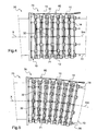
- the Figure 2 shows two rings 10 held coaxially by connecting elements 32 formed of silentblocs which will be described first in detail with reference to the Figure 3 .
- These connecting elements 32 have two opposed rigid fastening portions 34, 36 and a deformable elastic body 38 intended to be interposed between the two fastening portions 34, 36.
- One of the rigid fastening portions 34 comprises a receiving sleeve 40 having a bottom 42 and oppositely an opening 44.
- the receiving sleeve 40 is provided with a socket rod 46 intended to be fixed axially to the bottom 42 and the opposite of the opening 44.
- the Socket rod 46 has a length substantially greater than the axial width l12 of the outer ring 12 and moreover, its free end 48 is threaded so as to receive a nut 50. In this way, it can be engaged inside.
- axial bores 30 so as to secure the receiving sleeve 40 and the outer ring 12.
- the other rigid portion 36 comprises a frustoconical member 52 having at the base a flange 54 and at the opposite a tip portion 56.
- the frustoconical member 52 is also provided with a frustoconical member rod 58 mounted to be coaxially secured in the base at the flange 54.
- the frustoconical member rod 58 extends opposite the tip portion 56 and its free end 60 is also threaded to receive a second nut 62.
- the frustoconical member shaft 58 also has a length substantially greater than the axial width l12 of the outer ring 12 and is adapted to be engaged inside the axial bores 30 to secure the frustoconical member 52 to the outer ring 12.
- the elastic deformable body 38 consists of a hollow cylindrical member made of polymeric material of elastomer type, for example polyurethane.
- the hollow cylindrical member of the deformable elastic body 38 has an inlet opening 64 and an opposite bottom wall 66 closing it.
- the inlet opening 64 is extended by a substantially frustoconical space 68, the base of this space being oriented towards the inlet opening 64, whereas the point of this space is directed towards the bottom wall 66.
- the substantially frustoconical space 68 has dimensions close to those of the frustoconical member 52 so as to be able to receive it.
- the two rings shown on the Figure 2 are matched by means of eight connecting elements 32 of the type illustrated on the Figure 3 .
- the two rings 10 are coaxially adjusted and their flanks 18,16 opposite, while their sixteen axial holes 30 respectively are located vis-à-vis.
- the connecting elements 32 comprising their two rigid fastening portions 34, 36 and their deformable elastic body 38, on the other hand, are installed step by step every two pairs of axial bores 30.
- a connecting element 32 is installed step by step every two pairs of axial bores 30.
- the socket rod 46 is then engaged in an axial bore 30, while the frustoconical member rod 58 is engaged in the axial bore 30 opposite.
- the nuts 50, 62 are respectively screwed onto the respective free ends 48, 60 of the rods to firstly hold the sleeve 40 in abutment against the circular edge 28 of one of the rings 10, and secondly to maintain the corresponding frustoconical member 52 bearing against the circular edge 28 of the other ring 10.
- the frustoconical member 52 is engaged within the frustoconical space 68 of the deformable elastic body 38.
- the other seven connecting elements 32 are adjusted in the same way to finally hold together the two rings 10.
- the eight other axial holes 30 are intended to receive, for the ring 10 located on the right on the Figure 2 , the socket rod 46 of a second series of connecting elements 32 to connect to a third ring not shown.
- FIG. 4 illustrating a tip 70 of a flexible tubular pipe 72 of axis of symmetry X.
- the tip 70 and then equipped with a protective sleeve 74 according to the invention, here comprising a set of eight successive rings 10 and connected together in a manner as illustrated in FIG. Figure 2 .
- a protective sleeve 74 according to the invention, here comprising a set of eight successive rings 10 and connected together in a manner as illustrated in FIG. Figure 2 .
- the rings 10 are fitted coaxially around a portion 71 of the flexible pipe 72.
- All the rings 10 are paired in pairs by means of eight connecting elements 32 and thus, the connecting elements 32 are adjusted. staggered with respect to the cylindrical surface defined by the outer rings 12.
- the frustoconical member 72 of the elements of link 32 tends to emerge from the receiving sleeve 40 and to stretch the elastic deformable body 38 which conversely also offers a tensile strength.
- the protective sleeve 74 makes it possible to offer resistance to the flexing the driving portion 71.
- Another advantage of the invention lies in bringing the flanges 20, 22 of the successive rings 10 into contact with the inside of the curvature, when this becomes too great and the connecting elements 32 are no longer sufficient to control this curvature.
- the flanges 22, at the inner portions 76 of rings 10 successively abut against each other and then block the flexion of the portion 71 of flexible pipe 72 fitted into the protective sleeve 74.
- the sleeve protection according to the invention has all the functions of a stiffener and moreover, that of a curvature limiter beyond which the portion of pipe that surrounds it can not be bent.
- the protective sleeve according to the invention is not limited to eight rings. It is thus planned to form protective sleeves including many more rings so as to limit the curvature of longer pipe portions.
- the number of connecting elements 32 to match two rings is also not limiting. For example, it is expected to pair the rings in pairs by means of ten connecting elements.
- the diameter of the protective sleeve it is obviously adapted to the outer diameter of the flexible pipe to preserve. As a result, lower ring diameters, for example 0.4 m, are provided.
- a cable 80 extends in the axial direction along the protective sleeve.
- a first end of the cable is fixed on the end of the flexible pipe, while other points of attachment are also distributed along the protective sleeve.
- rings consisting of two adjustable half-rings and held together by bolting in order to be able to more easily replace the damaged rings of the set of rings constituting the protective sleeve.
- the embodiment described is in no way limiting of the invention.
- connecting elements with elastically deformable elements of different lengths For example, deformable elements of short length could be installed on the rings closest to the tip. Then connecting elements with elastic bodies of longer lengths could be placed on the rings furthest away from the tip.
Claims (9)
- Schutzhülse für die Installation um einen längsgerichteten Abschnitt einer flexiblen Rohrleitung (72) herum, die für den Transport von Kohlenwasserstoffen bestimmt ist, um der Biegung des längsgerichteten Abschnitts in einer beliebigen Krümmung standzuhalten, wobei die Hülse eine Anordnung von Ringen umfasst, die jeweils zwei entgegengesetzte Flanken (16, 18) aufweisen, wobei die Ringe (10) der Anordnung nacheinander in koaxialer Richtung zusammen und die Flanken (16, 18) jeweils gegenüber gehalten werden durch eine Vielzahl von axialen, elastisch verformbaren Verbindungselementen (32), die zwischen den Flanken (16, 18) der Ringe (10) kreisförmig verteilt sind, wobei die Biegung des längsgerichteten Abschnitts dafür geeignet ist, das Zusammenziehen der Verbindungselemente (32), die zum Inneren der Krümmung hin befindlich sind, und gleichzeitig das Dehnen der entgegengesetzten Verbindungselemente (32), die zum Äußeren der Krümmung hin befindlich sind, zu bewirken, um der Biegung des längsgerichteten Abschnitts der flexiblen Rohrleitung (72) standzuhalten;
dadurch gekennzeichnet, dass jedes Verbindungselement (32) zwei entgegengesetzte steife Befestigungsteile (34, 36) und einen verformbaren elastischen Körper (38) aufweist, der zwischen den zwei Befestigungsteilen angeordnet ist, um die relative Bewegung der zwei Befestigungsteile zu gestatten, indem er Rückstellkräfte an den Befestigungsteilen erzeugt;
und dass die Befestigungsteile (34, 36) jedes Verbindungselements (32) jeweils in den Flanken (16, 18) den Ringen (10) gegenüber befestigt sind, derart, dass die Biegung des längsgerichteten Abschnitts der Rohrleitung das Zusammendrücken des verformbaren elastischen Körpers (38) der axialen Verbindungselemente (32) vom Inneren der Krümmung und das Ziehen der axialen Verbindungselemente (32) vom Äußeren der Krümmung bewirken kann, um die Rückstellkräfte auf die Ringe (10) zu übertragen. - Schutzhülse nach Anspruch 1, dadurch gekennzeichnet, dass der verformbare elastische Körper (38) aus Polymermaterial realisiert ist.
- Schutzhülse nach Anspruch 1 oder 2, dadurch gekennzeichnet, dass die Flanken (16, 18) jedes Rings (10) einen innen liegenden kreisförmigen Rücksprung (20, 22) aufweisen, der zu der Mitte des Rings (10) hin befindlich ist, und dass die Ringe der Anordnung von Ringen einander angenähert gehalten werden, derart, dass die Biegung des längsgerichteten Abschnitts ferner bewirken kann, dass Abschnitte des innen liegenden kreisförmigen Rücksprungs (20, 22) der Ringe (10), die zum Inneren der Krümmung hin befindlich sind, jeweils in Kontakt gebracht werden, um die Biegung des längsgerichteten Abschnitts der Rohrleitung (72) zu blockieren.
- Schutzhülse nach Anspruch 3, dadurch gekennzeichnet, dass die Flanken (16, 18) der Ringe (10) einen außen liegenden kreisförmigen Rand (28) aufweisen, welcher der Mitte des Rings relativ zu dem innen liegenden kreisförmigen Rücksprung (20, 22) entgegengesetzt angeordnet ist, und dass die Befestigungsteile (34, 36) jedes Verbindungselements jeweils in den außen liegenden kreisförmigen Rändern (28) befestigt sind.
- Schutzhülse nach Anspruch 3 oder 4, dadurch gekennzeichnet, dass die Ringe (10) jeweils von zwei konzentrischen Reifen (12, 14) gebildet sind, die ineinander gesteckt sind.
- Schutzhülse nach einem der Ansprüche 1 bis 5, dadurch gekennzeichnet, dass die zwei steifen entgegengesetzten Befestigungsteile (34, 36) einerseits eine Aufnahmebuchse mit einem Boden (42) und einer Öffnung (44) und andererseits ein im Wesentlichen kegelstumpfförmiges Organ (52) umfassen, das dafür angepasst ist, durch die Öffnung (44) hindurch einzutreten, derart, dass die Spitze (56) des kegelstumpfförmigen Organs zu dem Boden (42) hin ausgerichtet ist, während der verformbare elastische Körper (38) ein zylindrisches Hohlorgan umfasst, das dafür angepasst ist, in das Innere der Buchse (40) einzutreten und das kegelstumpfförmige Organ (52) aufzunehmen.
- Schutzhülse nach Anspruch 5, dadurch gekennzeichnet, dass die Aufnahmebuchse (40) einen Buchsenschaft (46) aufweist, der mit dem Boden (42) fest verbunden ist und sich nach außerhalb der Buchse hin und der Öffnung entgegengesetzt erstreckt, wobei der Buchsenschaft (46) dafür bestimmt ist, durch die Ringe (10) hindurch in einer axialen Richtung einzutreten, um die Buchse (40) mit den Ringen fest zu verbinden.
- Schutzhülse nach Anspruch 5 oder 6, dadurch gekennzeichnet, dass das kegelstumpfförmige Organ (52) einen kegelstumpfförmigen Organschaft (58) aufweist, der mit dem kegelstumpfförmigen Organ fest verbunden ist und sich zu der Spitze (56) entgegengesetzt erstreckt, wobei der kegelstumpfförmige Organschaft dafür bestimmt ist, durch die Ringe (10) hindurch in einer axialen Richtung einzutreten, um das kegelstumpfförmige Organ (52) mit den Ringen fest zu verbinden.
- Schutzhülse nach einem der Ansprüche 1 bis 8, dadurch gekennzeichnet, dass die Ringe (10) der Anordnung jeweils von zwei Halbschalen gebildet sind, die durch Verschraubung zusammengefügt sind.
Priority Applications (1)
| Application Number | Priority Date | Filing Date | Title |
|---|---|---|---|
| CY20131101092T CY1114700T1 (el) | 2009-03-24 | 2013-12-03 | Προστατευτικο περιβλημα για ευκαμπτο αγωγο |
Applications Claiming Priority (2)
| Application Number | Priority Date | Filing Date | Title |
|---|---|---|---|
| FR0901378A FR2943758B1 (fr) | 2009-03-24 | 2009-03-24 | Manchon de protection pour conduite flexible |
| PCT/FR2010/050514 WO2010109124A1 (fr) | 2009-03-24 | 2010-03-22 | Manchon de protection pour conduite flexible |
Publications (2)
| Publication Number | Publication Date |
|---|---|
| EP2411717A1 EP2411717A1 (de) | 2012-02-01 |
| EP2411717B1 true EP2411717B1 (de) | 2013-09-04 |
Family
ID=41226804
Family Applications (1)
| Application Number | Title | Priority Date | Filing Date |
|---|---|---|---|
| EP10716568.0A Active EP2411717B1 (de) | 2009-03-24 | 2010-03-22 | Schutzhülse für ein flexibles rohr |
Country Status (15)
| Country | Link |
|---|---|
| US (1) | US9188266B2 (de) |
| EP (1) | EP2411717B1 (de) |
| CN (1) | CN102439343B (de) |
| AP (1) | AP3175A (de) |
| AU (1) | AU2010227404B2 (de) |
| BR (1) | BRPI1011257B1 (de) |
| CA (1) | CA2755872C (de) |
| CY (1) | CY1114700T1 (de) |
| ES (1) | ES2438502T3 (de) |
| FR (1) | FR2943758B1 (de) |
| MX (1) | MX2011009998A (de) |
| MY (1) | MY159240A (de) |
| NZ (1) | NZ595267A (de) |
| TN (1) | TN2011000476A1 (de) |
| WO (1) | WO2010109124A1 (de) |
Families Citing this family (10)
| Publication number | Priority date | Publication date | Assignee | Title |
|---|---|---|---|---|
| AU2013214592A1 (en) * | 2012-02-02 | 2014-08-07 | National Oilwell Varco Denmark I/S | Bend limiter |
| AU2013405481B2 (en) * | 2013-11-14 | 2018-04-26 | Equinor Energy As | Bend stiffener |
| FR3017178B1 (fr) * | 2014-02-06 | 2016-09-02 | Delfingen Fr-Anteuil S A | Gaine tubulaire annelee comportant un moyen de serrage interieur |
| CN105317220B (zh) * | 2014-07-18 | 2017-05-24 | 中联重科股份有限公司 | 物料输送的软管保护装置、布料机构及混凝土泵送设备 |
| US10008840B2 (en) | 2015-07-20 | 2018-06-26 | Magnetic Lifting Technologies US, LLC | Flexible clad protection system |
| US9982800B2 (en) * | 2015-08-12 | 2018-05-29 | Tor Persson | Bending restrictor assembly for permanently bending and restraining ovality of a subsea pipe |
| CN105268695B (zh) * | 2015-10-28 | 2018-08-10 | 芜湖市恒浩机械制造有限公司 | 一种阀门吹尘枪 |
| EP3649389A4 (de) * | 2017-08-09 | 2020-07-08 | Tor Persson | Krümmungsbeschränkungsanordnung zur dauerhaften biegung und rückhaltung der ovalität eines unterwasserrohrs |
| CN111779921B (zh) * | 2020-07-03 | 2022-03-22 | 合肥市久环给排水燃气设备有限公司 | 一种燃气管道的防护装置 |
| CN115899443B (zh) * | 2022-12-24 | 2023-11-21 | 常州松英视液镜有限公司 | 一种柔性防护套管及此柔性防护套管的加工工艺 |
Family Cites Families (36)
| Publication number | Priority date | Publication date | Assignee | Title |
|---|---|---|---|---|
| US982482A (en) * | 1910-04-27 | 1911-01-24 | William Thomas Donnelly | Flexible pipe. |
| US1677077A (en) * | 1927-09-20 | 1928-07-10 | Burwell B Byers | Hose protector |
| US3323552A (en) * | 1964-09-29 | 1967-06-06 | Honeywell Inc | Deflectable tube |
| US3833267A (en) * | 1972-11-30 | 1974-09-03 | Green Refractories | Liner and process for combating wear in pneumatic transport systems |
| JPS57111904A (en) * | 1980-12-27 | 1982-07-12 | Horiba Ltd | Flexible cable |
| GB2142788B (en) * | 1983-06-08 | 1987-05-20 | British Telecomm | Bend limiter for cables |
| US4527928A (en) * | 1983-07-15 | 1985-07-09 | Texaco Inc. | Protective riser-conductor for offshore structures |
| US4700693A (en) * | 1985-12-09 | 1987-10-20 | Welch Allyn, Inc. | Endoscope steering section |
| IT1186157B (it) * | 1985-12-20 | 1987-11-18 | Pirelli Cavi Spa | Dispositivo per limitare la curvatura di una porzione di cavo sottomarino |
| US4722631A (en) * | 1986-05-21 | 1988-02-02 | Musashi Seimitsu Kogyo Kabushiki Kaisha | Ball-and-socket joint with rubber-cushioned ball |
| US4790294A (en) * | 1987-07-28 | 1988-12-13 | Welch Allyn, Inc. | Ball-and-socket bead endoscope steering section |
| US4796607A (en) * | 1987-07-28 | 1989-01-10 | Welch Allyn, Inc. | Endoscope steering section |
| US5005558A (en) * | 1988-05-16 | 1991-04-09 | Kabushiki Kaisha Toshiba | Endoscope |
| US4976288A (en) * | 1989-06-22 | 1990-12-11 | Dynamic Air, Inc. | Tubing bend for pneumatic conveying system |
| US5161828A (en) * | 1991-07-31 | 1992-11-10 | Cooper Industries, Inc. | Break-away flowline fitting |
| GB9123760D0 (en) * | 1991-11-08 | 1992-01-02 | Stockman Anthony J | Optical fibre sheathing |
| US5439323A (en) * | 1993-07-09 | 1995-08-08 | Westinghouse Electric Corporation | Rod and shell composite riser |
| MY123038A (en) * | 1995-07-25 | 2006-05-31 | Impact Surge Sdn Bhd | Apparatus for the combatting of underwater growth on submerged structures |
| NO302786B1 (no) * | 1996-08-14 | 1998-04-20 | Alcatel Kabel Norge As | Böyebegrenser |
| GB9703144D0 (en) * | 1997-02-14 | 1997-04-02 | Tyrer Andrew C R | Bend stiffeners |
| FR2760813B1 (fr) * | 1997-03-14 | 1999-04-09 | Coflexip | Dispositif limiteur de courbure d'une conduite flexible |
| US5873817A (en) * | 1997-05-12 | 1999-02-23 | Circon Corporation | Endoscope with resilient deflectable section |
| AUPO711097A0 (en) * | 1997-06-02 | 1997-06-26 | National Valve & Engineering Company Pty. Limited | Hose protector system |
| US6599496B2 (en) * | 1999-04-30 | 2003-07-29 | Chek-Med Systems, Inc. | Endoscopy tissue stain |
| US6095197A (en) * | 1999-10-11 | 2000-08-01 | Cascade Waterworks Manufacturing Co., Inc. | Pipe coupling stiffener |
| TW490386B (en) * | 2000-05-01 | 2002-06-11 | Ashimori Ind Co Ltd | Duct repairing material, repairing structure, and repairing method |
| NL1016610C2 (nl) * | 2000-11-15 | 2002-05-16 | Lankhorst Recycling Bv | Beschermelement voor een stijgbuissegment. |
| US6561714B1 (en) * | 2000-11-20 | 2003-05-13 | Michael R. Williams | Breakaway joint for subsea components |
| US6878149B2 (en) * | 2002-03-25 | 2005-04-12 | Acueity, Inc. | Apparatus and method for intraductal abalation |
| US7699353B2 (en) * | 2004-05-07 | 2010-04-20 | Deep Down, Inc. | Compliant splice |
| NO20043980A (no) * | 2004-09-23 | 2006-03-13 | Marine Subsea Group As | Bøyestiver |
| US7451784B2 (en) * | 2005-01-25 | 2008-11-18 | Advanced Drainage Systems, Inc. | Corrugated pipe with perforation protecting cover |
| US7413021B2 (en) * | 2005-03-31 | 2008-08-19 | Schlumberger Technology Corporation | Method and conduit for transmitting signals |
| US7469722B2 (en) * | 2006-12-19 | 2008-12-30 | Norvald Berland | Segmented bend stiffener |
| EP2524147A1 (de) * | 2009-12-14 | 2012-11-21 | Phibre Pty Ltd | Unterwasserverbindungssystem |
| MX368126B (es) * | 2010-06-21 | 2019-09-19 | Khachaturian Jon | Metodo y aparato para elevar una plataforma marina. |
-
2009
- 2009-03-24 FR FR0901378A patent/FR2943758B1/fr active Active
-
2010
- 2010-03-22 US US13/257,743 patent/US9188266B2/en active Active
- 2010-03-22 CN CN201080022471.2A patent/CN102439343B/zh active Active
- 2010-03-22 NZ NZ595267A patent/NZ595267A/xx unknown
- 2010-03-22 AP AP2011005942A patent/AP3175A/xx active
- 2010-03-22 BR BRPI1011257-0A patent/BRPI1011257B1/pt active IP Right Grant
- 2010-03-22 MY MYPI2011004438A patent/MY159240A/en unknown
- 2010-03-22 WO PCT/FR2010/050514 patent/WO2010109124A1/fr active Application Filing
- 2010-03-22 CA CA2755872A patent/CA2755872C/fr active Active
- 2010-03-22 MX MX2011009998A patent/MX2011009998A/es active IP Right Grant
- 2010-03-22 EP EP10716568.0A patent/EP2411717B1/de active Active
- 2010-03-22 ES ES10716568.0T patent/ES2438502T3/es active Active
- 2010-03-22 AU AU2010227404A patent/AU2010227404B2/en active Active
-
2011
- 2011-09-21 TN TN2011000476A patent/TN2011000476A1/fr unknown
-
2013
- 2013-12-03 CY CY20131101092T patent/CY1114700T1/el unknown
Also Published As
| Publication number | Publication date |
|---|---|
| US9188266B2 (en) | 2015-11-17 |
| MX2011009998A (es) | 2012-01-20 |
| ES2438502T3 (es) | 2014-01-17 |
| FR2943758B1 (fr) | 2011-03-25 |
| BRPI1011257A2 (pt) | 2016-03-22 |
| US20120048415A1 (en) | 2012-03-01 |
| BRPI1011257B1 (pt) | 2019-06-04 |
| CA2755872A1 (fr) | 2010-09-30 |
| FR2943758A1 (fr) | 2010-10-01 |
| CY1114700T1 (el) | 2016-10-05 |
| MY159240A (en) | 2016-12-30 |
| NZ595267A (en) | 2013-04-26 |
| CA2755872C (fr) | 2017-03-14 |
| AU2010227404A1 (en) | 2011-10-20 |
| TN2011000476A1 (en) | 2013-03-27 |
| EP2411717A1 (de) | 2012-02-01 |
| AP2011005942A0 (en) | 2011-10-31 |
| CN102439343A (zh) | 2012-05-02 |
| CN102439343B (zh) | 2014-02-26 |
| AU2010227404B2 (en) | 2015-04-02 |
| AP3175A (en) | 2015-03-31 |
| WO2010109124A1 (fr) | 2010-09-30 |
Similar Documents
| Publication | Publication Date | Title |
|---|---|---|
| EP2411717B1 (de) | Schutzhülse für ein flexibles rohr | |
| EP3469244B1 (de) | Verbindungsendstück für eine flexible leitung und zugehörige flexible leitung und verfahren | |
| EP3014157B1 (de) | Schlauch und verfahren dafür | |
| FR3074251A1 (fr) | Embout de connexion d'une conduite flexible de transport de fluide, conduite et procede associes | |
| FR3014165A1 (fr) | Embout de connexion d'une conduite flexible avec ancrage des fils d'armure par coincement | |
| WO2009147064A1 (fr) | Conduite flexible à embouts d'extrémité intégrés | |
| EP1859187B1 (de) | Gegen schwingungen geschützter schlauch | |
| EP1678435B1 (de) | Führungsrohr für einen flexiblen kanal zum transport von kohlenwasserstoffen | |
| WO2009004183A2 (fr) | Tubulure flexible à tuyau onduleux et protection mécanique externe | |
| EP2497172B1 (de) | Elektroverbinder in einer turbomaschine | |
| EP2379900B1 (de) | Befestigungsvorrichtung für hydraulikschläuche | |
| EP0517897B1 (de) | Versteifung mit einer verstärkten struktur | |
| WO2013083597A1 (fr) | Ensemble d'un embout de connexion et d'une conduite flexible de transport d'un fluide cryogénique | |
| EP1605195B1 (de) | Rohrkupplungssystem und dazu gehöriges Montageverfahren | |
| FR3021625A1 (fr) | Liaison flexible entre la structure plancher et la structure de coque d'un aeronef. | |
| EP3095716B1 (de) | Versorgungs-anschlussmodul für trägerrakete | |
| EP3674590A1 (de) | Vorrichtung zum befestigen eines elements auf einer leitung, befestigungssystem, installation und umsetzungsverfahren | |
| WO2017080857A1 (fr) | Module pour le transport d'un fluide et méthode de raccordement d'une structure tissée et d'un raccord d'extrémité | |
| EP3022477A1 (de) | Verbindungsendstück eines schlauchs und entsprechender schlauch | |
| FR3026151A1 (fr) | Dispositif d'assemblage a ecrou-barillet, ensemble structurel d'aeronef comprenant un tel dispositif, et procede d'assemblage correspondant | |
| WO2009066027A1 (fr) | Procede de montage d'un embout sur une conduite pour former un raccord |
Legal Events
| Date | Code | Title | Description |
|---|---|---|---|
| PUAI | Public reference made under article 153(3) epc to a published international application that has entered the european phase |
Free format text: ORIGINAL CODE: 0009012 |
|
| 17P | Request for examination filed |
Effective date: 20111024 |
|
| AK | Designated contracting states |
Kind code of ref document: A1 Designated state(s): AT BE BG CH CY CZ DE DK EE ES FI FR GB GR HR HU IE IS IT LI LT LU LV MC MK MT NL NO PL PT RO SE SI SK SM TR |
|
| DAX | Request for extension of the european patent (deleted) | ||
| GRAP | Despatch of communication of intention to grant a patent |
Free format text: ORIGINAL CODE: EPIDOSNIGR1 |
|
| RIC1 | Information provided on ipc code assigned before grant |
Ipc: E21B 17/01 20060101ALI20130319BHEP Ipc: F16L 1/12 20060101AFI20130319BHEP Ipc: F16L 57/02 20060101ALI20130319BHEP Ipc: F16L 35/00 20060101ALI20130319BHEP |
|
| INTG | Intention to grant announced |
Effective date: 20130412 |
|
| GRAS | Grant fee paid |
Free format text: ORIGINAL CODE: EPIDOSNIGR3 |
|
| GRAA | (expected) grant |
Free format text: ORIGINAL CODE: 0009210 |
|
| RAP1 | Party data changed (applicant data changed or rights of an application transferred) |
Owner name: TECHNIP FRANCE |
|
| AK | Designated contracting states |
Kind code of ref document: B1 Designated state(s): AT BE BG CH CY CZ DE DK EE ES FI FR GB GR HR HU IE IS IT LI LT LU LV MC MK MT NL NO PL PT RO SE SI SK SM TR |
|
| REG | Reference to a national code |
Ref country code: GB Ref legal event code: FG4D Free format text: NOT ENGLISH |
|
| REG | Reference to a national code |
Ref country code: CH Ref legal event code: EP |
|
| REG | Reference to a national code |
Ref country code: AT Ref legal event code: REF Ref document number: 630732 Country of ref document: AT Kind code of ref document: T Effective date: 20130915 |
|
| RAP2 | Party data changed (patent owner data changed or rights of a patent transferred) |
Owner name: TECHNIP FRANCE |
|
| REG | Reference to a national code |
Ref country code: IE Ref legal event code: FG4D Free format text: LANGUAGE OF EP DOCUMENT: FRENCH |
|
| REG | Reference to a national code |
Ref country code: DE Ref legal event code: R096 Ref document number: 602010010011 Country of ref document: DE Effective date: 20131031 |
|
| REG | Reference to a national code |
Ref country code: NL Ref legal event code: T3 |
|
| REG | Reference to a national code |
Ref country code: AT Ref legal event code: MK05 Ref document number: 630732 Country of ref document: AT Kind code of ref document: T Effective date: 20130904 |
|
| REG | Reference to a national code |
Ref country code: ES Ref legal event code: FG2A Ref document number: 2438502 Country of ref document: ES Kind code of ref document: T3 Effective date: 20140117 |
|
| REG | Reference to a national code |
Ref country code: NO Ref legal event code: T2 Effective date: 20130904 |
|
| PG25 | Lapsed in a contracting state [announced via postgrant information from national office to epo] |
Ref country code: AT Free format text: LAPSE BECAUSE OF FAILURE TO SUBMIT A TRANSLATION OF THE DESCRIPTION OR TO PAY THE FEE WITHIN THE PRESCRIBED TIME-LIMIT Effective date: 20130904 Ref country code: LT Free format text: LAPSE BECAUSE OF FAILURE TO SUBMIT A TRANSLATION OF THE DESCRIPTION OR TO PAY THE FEE WITHIN THE PRESCRIBED TIME-LIMIT Effective date: 20130904 Ref country code: HR Free format text: LAPSE BECAUSE OF FAILURE TO SUBMIT A TRANSLATION OF THE DESCRIPTION OR TO PAY THE FEE WITHIN THE PRESCRIBED TIME-LIMIT Effective date: 20130904 Ref country code: SE Free format text: LAPSE BECAUSE OF FAILURE TO SUBMIT A TRANSLATION OF THE DESCRIPTION OR TO PAY THE FEE WITHIN THE PRESCRIBED TIME-LIMIT Effective date: 20130904 |
|
| REG | Reference to a national code |
Ref country code: LT Ref legal event code: MG4D |
|
| PG25 | Lapsed in a contracting state [announced via postgrant information from national office to epo] |
Ref country code: FI Free format text: LAPSE BECAUSE OF FAILURE TO SUBMIT A TRANSLATION OF THE DESCRIPTION OR TO PAY THE FEE WITHIN THE PRESCRIBED TIME-LIMIT Effective date: 20130904 Ref country code: GR Free format text: LAPSE BECAUSE OF FAILURE TO SUBMIT A TRANSLATION OF THE DESCRIPTION OR TO PAY THE FEE WITHIN THE PRESCRIBED TIME-LIMIT Effective date: 20131205 Ref country code: LV Free format text: LAPSE BECAUSE OF FAILURE TO SUBMIT A TRANSLATION OF THE DESCRIPTION OR TO PAY THE FEE WITHIN THE PRESCRIBED TIME-LIMIT Effective date: 20130904 Ref country code: PL Free format text: LAPSE BECAUSE OF FAILURE TO SUBMIT A TRANSLATION OF THE DESCRIPTION OR TO PAY THE FEE WITHIN THE PRESCRIBED TIME-LIMIT Effective date: 20130904 Ref country code: SI Free format text: LAPSE BECAUSE OF FAILURE TO SUBMIT A TRANSLATION OF THE DESCRIPTION OR TO PAY THE FEE WITHIN THE PRESCRIBED TIME-LIMIT Effective date: 20130904 |
|
| PG25 | Lapsed in a contracting state [announced via postgrant information from national office to epo] |
Ref country code: CZ Free format text: LAPSE BECAUSE OF FAILURE TO SUBMIT A TRANSLATION OF THE DESCRIPTION OR TO PAY THE FEE WITHIN THE PRESCRIBED TIME-LIMIT Effective date: 20130904 Ref country code: RO Free format text: LAPSE BECAUSE OF FAILURE TO SUBMIT A TRANSLATION OF THE DESCRIPTION OR TO PAY THE FEE WITHIN THE PRESCRIBED TIME-LIMIT Effective date: 20130904 Ref country code: EE Free format text: LAPSE BECAUSE OF FAILURE TO SUBMIT A TRANSLATION OF THE DESCRIPTION OR TO PAY THE FEE WITHIN THE PRESCRIBED TIME-LIMIT Effective date: 20130904 Ref country code: IS Free format text: LAPSE BECAUSE OF FAILURE TO SUBMIT A TRANSLATION OF THE DESCRIPTION OR TO PAY THE FEE WITHIN THE PRESCRIBED TIME-LIMIT Effective date: 20140104 Ref country code: SK Free format text: LAPSE BECAUSE OF FAILURE TO SUBMIT A TRANSLATION OF THE DESCRIPTION OR TO PAY THE FEE WITHIN THE PRESCRIBED TIME-LIMIT Effective date: 20130904 |
|
| REG | Reference to a national code |
Ref country code: DE Ref legal event code: R097 Ref document number: 602010010011 Country of ref document: DE |
|
| PG25 | Lapsed in a contracting state [announced via postgrant information from national office to epo] |
Ref country code: PT Free format text: LAPSE BECAUSE OF FAILURE TO SUBMIT A TRANSLATION OF THE DESCRIPTION OR TO PAY THE FEE WITHIN THE PRESCRIBED TIME-LIMIT Effective date: 20140106 |
|
| PLBE | No opposition filed within time limit |
Free format text: ORIGINAL CODE: 0009261 |
|
| STAA | Information on the status of an ep patent application or granted ep patent |
Free format text: STATUS: NO OPPOSITION FILED WITHIN TIME LIMIT |
|
| 26N | No opposition filed |
Effective date: 20140605 |
|
| REG | Reference to a national code |
Ref country code: DE Ref legal event code: R097 Ref document number: 602010010011 Country of ref document: DE Effective date: 20140605 |
|
| PG25 | Lapsed in a contracting state [announced via postgrant information from national office to epo] |
Ref country code: DK Free format text: LAPSE BECAUSE OF FAILURE TO SUBMIT A TRANSLATION OF THE DESCRIPTION OR TO PAY THE FEE WITHIN THE PRESCRIBED TIME-LIMIT Effective date: 20130904 |
|
| REG | Reference to a national code |
Ref country code: DE Ref legal event code: R119 Ref document number: 602010010011 Country of ref document: DE |
|
| PG25 | Lapsed in a contracting state [announced via postgrant information from national office to epo] |
Ref country code: LU Free format text: LAPSE BECAUSE OF FAILURE TO SUBMIT A TRANSLATION OF THE DESCRIPTION OR TO PAY THE FEE WITHIN THE PRESCRIBED TIME-LIMIT Effective date: 20140322 |
|
| REG | Reference to a national code |
Ref country code: CH Ref legal event code: PL |
|
| REG | Reference to a national code |
Ref country code: FR Ref legal event code: ST Effective date: 20141128 |
|
| REG | Reference to a national code |
Ref country code: IE Ref legal event code: MM4A Ref country code: DE Ref legal event code: R119 Ref document number: 602010010011 Country of ref document: DE Effective date: 20141001 |
|
| PG25 | Lapsed in a contracting state [announced via postgrant information from national office to epo] |
Ref country code: LI Free format text: LAPSE BECAUSE OF NON-PAYMENT OF DUE FEES Effective date: 20140331 Ref country code: CH Free format text: LAPSE BECAUSE OF NON-PAYMENT OF DUE FEES Effective date: 20140331 Ref country code: IE Free format text: LAPSE BECAUSE OF NON-PAYMENT OF DUE FEES Effective date: 20140322 Ref country code: FR Free format text: LAPSE BECAUSE OF NON-PAYMENT OF DUE FEES Effective date: 20140331 Ref country code: DE Free format text: LAPSE BECAUSE OF NON-PAYMENT OF DUE FEES Effective date: 20141001 |
|
| REG | Reference to a national code |
Ref country code: FR Ref legal event code: D3 Effective date: 20150421 |
|
| PGRI | Patent reinstated in contracting state [announced from national office to epo] |
Ref country code: FR Effective date: 20150421 |
|
| PG25 | Lapsed in a contracting state [announced via postgrant information from national office to epo] |
Ref country code: MT Free format text: LAPSE BECAUSE OF FAILURE TO SUBMIT A TRANSLATION OF THE DESCRIPTION OR TO PAY THE FEE WITHIN THE PRESCRIBED TIME-LIMIT Effective date: 20130904 |
|
| REG | Reference to a national code |
Ref country code: FR Ref legal event code: PLFP Year of fee payment: 7 |
|
| PG25 | Lapsed in a contracting state [announced via postgrant information from national office to epo] |
Ref country code: SM Free format text: LAPSE BECAUSE OF FAILURE TO SUBMIT A TRANSLATION OF THE DESCRIPTION OR TO PAY THE FEE WITHIN THE PRESCRIBED TIME-LIMIT Effective date: 20130904 |
|
| PG25 | Lapsed in a contracting state [announced via postgrant information from national office to epo] |
Ref country code: MC Free format text: LAPSE BECAUSE OF FAILURE TO SUBMIT A TRANSLATION OF THE DESCRIPTION OR TO PAY THE FEE WITHIN THE PRESCRIBED TIME-LIMIT Effective date: 20130904 |
|
| PG25 | Lapsed in a contracting state [announced via postgrant information from national office to epo] |
Ref country code: BG Free format text: LAPSE BECAUSE OF FAILURE TO SUBMIT A TRANSLATION OF THE DESCRIPTION OR TO PAY THE FEE WITHIN THE PRESCRIBED TIME-LIMIT Effective date: 20130904 |
|
| PG25 | Lapsed in a contracting state [announced via postgrant information from national office to epo] |
Ref country code: HU Free format text: LAPSE BECAUSE OF FAILURE TO SUBMIT A TRANSLATION OF THE DESCRIPTION OR TO PAY THE FEE WITHIN THE PRESCRIBED TIME-LIMIT; INVALID AB INITIO Effective date: 20100322 Ref country code: TR Free format text: LAPSE BECAUSE OF FAILURE TO SUBMIT A TRANSLATION OF THE DESCRIPTION OR TO PAY THE FEE WITHIN THE PRESCRIBED TIME-LIMIT Effective date: 20130904 |
|
| REG | Reference to a national code |
Ref country code: FR Ref legal event code: PLFP Year of fee payment: 8 |
|
| REG | Reference to a national code |
Ref country code: FR Ref legal event code: PLFP Year of fee payment: 9 |
|
| PG25 | Lapsed in a contracting state [announced via postgrant information from national office to epo] |
Ref country code: MK Free format text: LAPSE BECAUSE OF FAILURE TO SUBMIT A TRANSLATION OF THE DESCRIPTION OR TO PAY THE FEE WITHIN THE PRESCRIBED TIME-LIMIT Effective date: 20130904 |
|
| PGFP | Annual fee paid to national office [announced via postgrant information from national office to epo] |
Ref country code: NO Payment date: 20230223 Year of fee payment: 14 Ref country code: FR Payment date: 20230330 Year of fee payment: 14 |
|
| PGFP | Annual fee paid to national office [announced via postgrant information from national office to epo] |
Ref country code: IT Payment date: 20230307 Year of fee payment: 14 Ref country code: CY Payment date: 20230221 Year of fee payment: 14 Ref country code: BE Payment date: 20230316 Year of fee payment: 14 |
|
| PGFP | Annual fee paid to national office [announced via postgrant information from national office to epo] |
Ref country code: ES Payment date: 20230405 Year of fee payment: 14 |
|
| PGFP | Annual fee paid to national office [announced via postgrant information from national office to epo] |
Ref country code: NL Payment date: 20240226 Year of fee payment: 15 |
|
| PGFP | Annual fee paid to national office [announced via postgrant information from national office to epo] |
Ref country code: GB Payment date: 20240325 Year of fee payment: 15 |