EP2410823A1 - Cyclotron for accelerating at least two kinds of particles - Google Patents
Cyclotron for accelerating at least two kinds of particles Download PDFInfo
- Publication number
- EP2410823A1 EP2410823A1 EP10170531A EP10170531A EP2410823A1 EP 2410823 A1 EP2410823 A1 EP 2410823A1 EP 10170531 A EP10170531 A EP 10170531A EP 10170531 A EP10170531 A EP 10170531A EP 2410823 A1 EP2410823 A1 EP 2410823A1
- Authority
- EP
- European Patent Office
- Prior art keywords
- pillar
- cavity
- transmission line
- frequency
- intermediate portion
- Prior art date
- Legal status (The legal status is an assumption and is not a legal conclusion. Google has not performed a legal analysis and makes no representation as to the accuracy of the status listed.)
- Granted
Links
- 239000002245 particle Substances 0.000 title claims description 21
- 230000005540 biological transmission Effects 0.000 claims abstract description 31
- 238000000034 method Methods 0.000 claims abstract description 8
- 238000004364 calculation method Methods 0.000 claims description 11
- 238000004088 simulation Methods 0.000 claims description 8
- 239000003990 capacitor Substances 0.000 claims description 6
- 230000001133 acceleration Effects 0.000 claims description 5
- 238000005457 optimization Methods 0.000 claims description 3
- 238000012512 characterization method Methods 0.000 claims 1
- 238000010586 diagram Methods 0.000 description 9
- 239000000243 solution Substances 0.000 description 9
- 230000005684 electric field Effects 0.000 description 5
- 230000014509 gene expression Effects 0.000 description 5
- 230000004913 activation Effects 0.000 description 4
- 230000000694 effects Effects 0.000 description 3
- 230000006378 damage Effects 0.000 description 2
- 230000009977 dual effect Effects 0.000 description 2
- 230000005284 excitation Effects 0.000 description 2
- 230000001965 increasing effect Effects 0.000 description 2
- 238000002347 injection Methods 0.000 description 2
- 239000007924 injection Substances 0.000 description 2
- RYGMFSIKBFXOCR-UHFFFAOYSA-N Copper Chemical compound [Cu] RYGMFSIKBFXOCR-UHFFFAOYSA-N 0.000 description 1
- 241001080024 Telles Species 0.000 description 1
- 241000897276 Termes Species 0.000 description 1
- 230000015556 catabolic process Effects 0.000 description 1
- 230000021615 conjugation Effects 0.000 description 1
- 238000010276 construction Methods 0.000 description 1
- 229910052802 copper Inorganic materials 0.000 description 1
- 239000010949 copper Substances 0.000 description 1
- 230000007423 decrease Effects 0.000 description 1
- 238000006731 degradation reaction Methods 0.000 description 1
- 230000004927 fusion Effects 0.000 description 1
- 238000010438 heat treatment Methods 0.000 description 1
- 238000002513 implantation Methods 0.000 description 1
- 230000001939 inductive effect Effects 0.000 description 1
- 238000002844 melting Methods 0.000 description 1
- 230000008018 melting Effects 0.000 description 1
- 230000004048 modification Effects 0.000 description 1
- 238000012986 modification Methods 0.000 description 1
- 230000010355 oscillation Effects 0.000 description 1
- 230000003068 static effect Effects 0.000 description 1
Images


Classifications
-
- H—ELECTRICITY
- H05—ELECTRIC TECHNIQUES NOT OTHERWISE PROVIDED FOR
- H05H—PLASMA TECHNIQUE; PRODUCTION OF ACCELERATED ELECTRICALLY-CHARGED PARTICLES OR OF NEUTRONS; PRODUCTION OR ACCELERATION OF NEUTRAL MOLECULAR OR ATOMIC BEAMS
- H05H7/00—Details of devices of the types covered by groups H05H9/00, H05H11/00, H05H13/00
- H05H7/14—Vacuum chambers
- H05H7/18—Cavities; Resonators
-
- H—ELECTRICITY
- H05—ELECTRIC TECHNIQUES NOT OTHERWISE PROVIDED FOR
- H05H—PLASMA TECHNIQUE; PRODUCTION OF ACCELERATED ELECTRICALLY-CHARGED PARTICLES OR OF NEUTRONS; PRODUCTION OR ACCELERATION OF NEUTRAL MOLECULAR OR ATOMIC BEAMS
- H05H13/00—Magnetic resonance accelerators; Cyclotrons
-
- H—ELECTRICITY
- H05—ELECTRIC TECHNIQUES NOT OTHERWISE PROVIDED FOR
- H05H—PLASMA TECHNIQUE; PRODUCTION OF ACCELERATED ELECTRICALLY-CHARGED PARTICLES OR OF NEUTRONS; PRODUCTION OR ACCELERATION OF NEUTRAL MOLECULAR OR ATOMIC BEAMS
- H05H7/00—Details of devices of the types covered by groups H05H9/00, H05H11/00, H05H13/00
- H05H7/02—Circuits or systems for supplying or feeding radio-frequency energy
Definitions
- the present invention relates to the field of cyclotrons, and in particular to cyclotrons capable of accelerating several types of charged particles having different charge (q) / mass (m) ratios, such as for example protons (equal q / m ratio at 1), alpha particles (ratio q / m equal to 1 ⁇ 2) or deuterons (ratio q / m also equal to 1 ⁇ 2).
- protons equal q / m ratio at 1
- alpha particles ratio q / m equal to 1 ⁇ 2
- deuterons ratio q / m also equal to 1 ⁇ 2
- such a cyclotron comprises acceleration electrodes 28, commonly called dice, each coupled to a vertical pillar 29 also called stem. Said die 28 and said pillar 29 are surrounded by a conductive enclosure which together constitute a resonant cavity.
- the resonant cavities are generally excited by an RF power source and the successive passage of the charged particles in the accelerator gap consisting of dice and sectors brought to different potentials produces the acceleration of said particles.
- a cyclotron can also operate in harmonic mode: in this case several oscillations of the RF voltage occur while the particles still circulate inside the die.
- the pillar forms an axial transmission line essentially having an inductance for compensating the capacitive impedance of the die to minimize reactive RF power.
- the cavities are arranged asymmetrically or symmetrically with respect to the median plane of circulation of the particles.
- the two plates constituting the die are mechanically and electrically integral and constitute a single assembly carried by the pillar.
- the lower and upper pillars respectively support the lower half-die and the upper half-die. These are electrically connected to each other at a few points in their perimeter as soon as the cyclotron is closed.
- the die is part of a resonant cavity 5 as schematically shown in FIG. figure 1a .
- This cavity comprises the actual dice 10, a vertical cylindrical pillar 20 and a conducting enclosure 40.
- figure 1c represents an equivalent circuit diagram of the cavity, in which the inductance L represents the pillar 20 and the capacitance C is that formed at the space between the die 10 and the conducting enclosure 40.
- the first two authors perform the RF frequency shift using sliding shorts, actuated by means of pistons, to change the length of the resonator.
- the last author proceeds to the change of frequency RF thanks to movable plates pivoting of 90 ° which modify the capacity of the electrodes and therefore the frequency of resonance.
- the present invention aims to solve at least partially the aforementioned difficulties.
- the present invention relates to a resonant cavity for the acceleration of charged particles in a cyclotron, comprising a die, a pillar and a conductive enclosure at least partially including said pillar and said die, an end of said pillar being integral with said a base of the conductive enclosure, an opposite end of said pillar supporting the die, the conductive enclosure and the pillar thus forming a transmission line, characterized in that the linear capacitance of an intermediate portion of said transmission line located between the ends of the pillar is substantially larger than the linear capacity of another portion of said transmission line.
- Such a configuration makes it possible to make the cavity resonate according to two modes thus producing two distinct frequencies, without having to make use of mobile elements such as, for example, sliding shorts or moving plates, which resolves many of the problems mentioned. previously.
- the linear capacitance of the intermediate portion of the transmission line is greater than twice the linear capacitance of another portion of said transmission line. More preferably, the linear capacity of the intermediate portion of the transmission line is greater than ten times the linear capacity of another portion of said transmission line.
- the characteristic impedance of the intermediate portion and the characteristic impedances of the other portions of the transmission line are such that the cavity is able to resonate in two modes to produce two distinct frequencies in a substantially double ratio.
- substantially double it is necessary to understand a frequency ratio lying between 1.7 and 2.3.
- Such a cavity makes it possible to accelerate, in the same cyclotron, particles having values of q / m in a ratio of two, such as for example protons and alpha particles or protons and deuterons.
- the pillar comprises a plurality of superimposed cylinders, one of these cylinders corresponding to said intermediate portion of the transmission line and having a mean diameter substantially greater than the average diameter of one of the other cylinders.
- the conductive enclosure comprises a plurality of superposed hollow cylinders, one of these hollow cylinders corresponding to said intermediate portion of the transmission line and having a mean diameter substantially smaller than the average diameter of one of the other hollow cylinders.
- the invention relates to a method for designing a dual-frequency resonant cavity as claimed.
- the figure 1a represents a section of an asymmetric resonant cavity of a cyclotron of the prior art
- the figure 1b represents a section of a symmetrical resonant cavity of a cyclotron of the prior art
- the figure 1c represents a simplified equivalent electrical diagram of the resonant cavity of the Figure 1a or 1b ;
- the figure 2a schematically represents a section of a cavity according to the invention with indication of the circulation of the current and the magnetic field during resonance at the low frequency;
- the figure 2b represents the evolution of the voltage and the current along the pillar during the operation of the cavity of the figure 2a in mode ;
- the Figure 2c represents a simplified equivalent electrical diagram of the resonant cavity of the figure 2a ;
- the figure 3a schematically represents a section of a resonant cavity according to the invention with indication of the circulation of currents and magnetic fields during resonance at the high frequency;
- the figure 3b represents the evolution of the voltage and the current along the pillar during the operation of the cavity of the figure 3a in mode ;
- the figure 3c represents a simplified equivalent electrical diagram of the resonant cavity of the figure 3a ;
- the figure 4a represents a real geometrical shape and a distribution of the equipotentials of a static electric field of a cavity of the prior art
- the figure 4b schematizes a cavity of the prior art in the form of a coaxial transmission line whose characteristic impedance is a function of the diameters d and D;
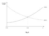
- the figure 5 represents a graph illustrating the power dissipated in a resonant cavity according to the invention for each of the two resonance frequencies as a function of the value of the capacitance of the characteristic low-impedance line portion;
- the figure 6a represents an impedance diagram of a pillar in an embodiment of the invention.
- the figure 6b schematically represents a section of the cavity according to the invention, to be related to the impedance diagram of the figure 6a ;
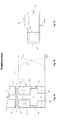
- the figure 7 represents a section of a bi-frequency cyclotron equipped with four cavities according to the invention.
- the figure 8 schematically represents a graph showing the two distinct frequencies in a double ratio obtained by frequency scanning of a cavity according to the invention.
- the figure 2a schematically represents an exemplary embodiment of a dual-frequency cavity according to the invention.
- This is a symmetrical cavity relative to the median plane of the cyclotron (represented by a mixed dotted line in the figure), but it is obvious that an asymmetrical cavity would also be suitable.
- the cavity 6 comprises two half-dice 10 and 10 'electrically connected together and between which will circulate the particles to accelerate, two pillars each comprising three portions 20a, 20b and 20c (20a', 20b 'and 20c'), and two conductive speakers 40 and 40 'surrounding the whole.
- the speakers have a cross section which, in this example, is substantially constant over the height of the pillars.
- Each pillar respectively supports a half-die at one end, the opposite ends being respectively electrically connected to the bases 45 and 45 'of the conductive speakers 40 and 40' to constitute a short circuit from the radiofrequency point of view.
- the different portions of the pillar are superimposed and preferably aligned along the same axis.
- Said portions consist, in this example, of cylindrical tubes of different diameters, examples of dimensions of which will be given below when a method of designing a cavity according to the invention will be described.
- the diameter of the intermediate portion 20b is substantially greater than the diameter of the other two portions 20a and 20c, so that the linear capacity (Farad per meter) of this intermediate portion 20b is substantially greater than the linear capacity of the other two portions 20a and 20c.
- the intermediate portion 20b will have a substantially capacitive behavior while the other portions 20a and 20c will have an essentially inductive behavior, in the operating frequency range of the cavity (which is in the megahertz).
- a simplified equivalent electrical diagram of such a cavity is presented at Figure 2c .
- a first type of operation is obtained by exciting the cavity in mode ( ⁇ being the wavelength), which makes it possible to obtain a first resonance frequency (hereinafter "the low resonance frequency", for example 33 MHz).
- the figure 2b represents the evolution of the voltage (U x ) and the current (I x ) in this mode as a function of an axial position x along the pillar. The voltage is maximum at the die while the corresponding current is zero or very low. This is reversed when one comes back to the foot of the pillar.
- This voltage configuration is particularly suitable for accelerating particles moving in the median plane of a cyclotron.
- the magnetic field B is oriented identically on either side of the intermediate portion 20b (hereinafter "the low impedance line 20b").
- the resulting current i 1 of this mode circulates axially and is distributed radially around the pillar as shown in FIG. figure 2a .
- FIG 3a A second type of operation is illustrated in figure 3a .
- the physical structure is identical to that of the figure 2a but we excite the mode , which makes it possible to obtain a second resonance frequency (hereinafter referred to as the "high resonance frequency", for example 66 MHz), higher than the first frequency.
- the figure 3b represents the evolution of the voltage (U x ) and current (I x ) in this mode and, identical to the first resonance mode, the voltage is always maximum at the die while the corresponding current is zero or very low. Furthermore, the current is reversed at an intermediate point about halfway up the low impedance line 20b, which has the effect of dividing the capacitive effect of this portion of line 20b in two.
- the figure 3c represents a simplified equivalent electrical diagram with the circulation of currents i 2 and i 3 respectively present in the upper and lower part of the half-cavity. They are distributed radially around the pillar, in opposition to a virtual horizontal plane transversely sharing the low impedance line 20b, in which they cancel each other out.
- an intermediate portion of the cavity has a linear capacity substantially greater than the linear capacity of the other portions, preferably greater than twice the linear capacity of the other portions, even more preferably greater than ten times the linear capacity of the other portions.
- a calculation method for designing and dimensioning a structure of a cavity according to the invention is provided below.
- the characteristic impedance of the known pillar is evaluated, for example using the Tricomp program of Field Precision LLC.
- This program solves the electric field by the finite element method.
- Z c 1 C . c 0 from which a value of Z c is obtained, which is 90.1 ohms in the case of the example.
- the surface currents in the cavity are then determined so as to evaluate the dissipated power and the quality factor. This can for example also be done using the Wavesim program. For a voltage of 50 kV present in the accelerator gap, the power dissipated in a cavity known according to the example provided is 1300 W and the quality factor Q is 10600. These values will serve as benchmarks for subsequent steps.
- the numerical values obtained during these first five steps then make it possible to calculate the structure of a two-frequency cavity according to the invention.
- the following steps of the calculation method according to the invention concern, by way of example, a cavity according to the Figures 2a and 3a and exploiting two resonant modes: a first mode to for a low frequency of about 33 MHz and a second mode to for a high frequency of about 66 MHz. It will be obvious to those skilled in the art to adapt what is necessary to adapt to these next steps for other frequencies and / or other frequency ratios.
- a final optimization of the two-frequency cavity is preferably carried out by 2D electromagnetic simulation, for example using the Wavesim program. It examines the variation of the resonant frequency as a function of the variation of the geometrical characteristics of the different portions of the pillar. In particular, the most delicate point is the optimization of the low impedance line 20b. Indeed, if its capacity is chosen too low, the dissipation at the high frequency (eg at 66 MHz) is important, as is the voltage developed at this point, in some cases as important as the one on the die. By increasing the value of the capacitance, the voltage decreases as well as the power dissipated in the bottom of the cavity.
- an optimum point C opt is preferably determined.
- the dissipated power is almost identical to the two resonance frequencies, as illustrated by figure 5 .
- FIG. figure 7 A practical embodiment of a cavity according to the invention and its implantation in a cyclotron is illustrated in FIG. figure 7 .
- the vertical section of this cyclotron makes it possible to distinguish four cavities according to the invention, only one of which has been annotated for clarity and comprehension.
- the resonance frequencies of the cavity can be verified by performing a frequency sweep ("wobbulation"). This provides a curve of variation of the impedance as a function of the frequency revealing two distinct peaks. According to the preferred example provided, there is a peak at substantially 33 MHz and a second peak at substantially 66 MHz, as shown schematically in FIG. figure 8 .
- the cavity 6 comprises a tuning capacitor 50 comprising a movable electrode electrically connected to the conducting enclosure 40 and placed opposite the pillar and substantially at the intermediate portion 20b. of the transmission line. This tuning capacitor 50 is visible on the figure 7 .
- a resonant cavity (6) bi-frequency cyclotron which comprises a die (10), a pillar (20) and a conductive enclosure (40) encompassing said pillar and said die , one end of the pillar being integral with the base of the conductive enclosure and an opposite end of said pillar (20) supporting the die (10).
- the conducting enclosure and the pillar form a transmission line comprising at least three portions (20a, 20b, 20c) each having a characteristic impedance (Z c1 , Z c2 , Z c3 ).
- the characteristic impedance Z c2 of the intermediate portion (20b) is substantially lower than the characteristic impedances Z c1 and Z c3 of the two other portions (20a, 20b), which makes it possible to make the cavity resonate according to two modes in order to produce two frequencies separate without having to use moving parts such as for example sliding shorts or moving plates.
Abstract
Description
La présente invention se rapporte au domaine des cyclotrons, et en particulier aux cyclotrons capables d'accélérer plusieurs types de particules chargées présentant des rapports charge(q)/masse(m) différents, tels que par exemple des protons (rapport q/m égal à 1), des particules alpha (rapport q/m égal à ½) ou des deutons (rapport q/m également égal à ½).The present invention relates to the field of cyclotrons, and in particular to cyclotrons capable of accelerating several types of charged particles having different charge (q) / mass (m) ratios, such as for example protons (equal q / m ratio at 1), alpha particles (ratio q / m equal to ½) or deuterons (ratio q / m also equal to ½).
On connaît par le document
Les cavités résonantes sont généralement excitées par une source de puissance RF et le passage successif des particules chargées dans le gap accélérateur constitué des dés et des secteurs portés à des potentiels différents produit l'accélération des dites particules. La fréquence de la tension RF appliquée doit être égale à la « fréquence cyclotron » exprimée par l'équation suivante: 
où q est la charge de la particule à accélérer, m sa masse et
where q is the charge of the particle to accelerate, m its mass and
Dans le cas de ces cavités connues, on est en présence d'un résonateur ![]()
![]()
Le dé fait partie d'une cavité résonante 5 tel que représentée schématiquement à la 
Afin de pouvoir accélérer plusieurs types de particules de rapports q/m différents dans un même cyclotron, le champ
- a) utiliser des modes harmoniques différents tout en conservant la fréquence RF identique
- b) utiliser le même mode harmonique tout en variant la fréquence RF
- une complexité accrue de la région centrale du cyclotron
- à haut courant, des pertes de faisceau à l'intérieur de la machine provoquant l'activation de pièces mécaniques.
- un même centrage des particules de masse différentes qui suivront donc une trajectoire similaire, au moins dans les premiers tours à basse énergie
- moins de pertes de faisceau réduisant ainsi l'activation des pièces mécaniques situées à proximité de la trajectoire du faisceau
- un meilleur gain par tour pour les particules de rapport q/m=1
- un meilleur isochronisme.
- a) use different harmonic modes while maintaining the same RF frequency
- b) use the same harmonic mode while varying the RF frequency
- increased complexity of the central cyclotron region
- at high current, beam losses inside the machine causing the activation of mechanical parts.
- the same centering of the different mass particles that will follow a similar trajectory, at least in the first low energy rounds
- fewer beam losses, thus reducing the activation of mechanical parts near the beam path
- a better gain per revolution for particles of ratio q / m = 1
- better isochronism.
La mise en oeuvre de cette seconde solution impose de pouvoir modifier la fréquence de résonance de la cavité constituée par le dé, le pilier et l'enceinte conductrice. De telles solutions ont été proposées par M.
Les deux premiers auteurs réalisent le changement de fréquence RF à l'aide de courts-circuits glissants, actionnés à l'aide de pistons, destinés à modifier la longueur du résonateur. Le dernier auteur procède au changement de fréquence RF grâce à des plaques mobiles pivotant de 90° qui modifient la capacité des électrodes et donc la fréquence de résonance.The implementation of this second solution requires the ability to modify the resonant frequency of the cavity formed by the die, the pillar and the conductive enclosure. Such solutions have been proposed by Mr.
The first two authors perform the RF frequency shift using sliding shorts, actuated by means of pistons, to change the length of the resonator. The last author proceeds to the change of frequency RF thanks to movable plates pivoting of 90 ° which modify the capacity of the electrodes and therefore the frequency of resonance.
Cette modification de la fréquence de résonance requiert une structure RF relativement complexe et onéreuse, à laquelle s'ajoutent des problèmes de fiabilité. En effet, les dispositifs de l'art antérieur présentent certains désavantages listés ci-après :
- a. pour les courts-circuits mobiles :
- la taille du piston est en rapport avec celle du court-circuit car celui-ci exerce une force de friction non négligeable sur les parois du résonateur ;
- l'usure causée par les mouvements linéaires répétés du court-circuit lors des changements de fréquence. A terme, la dégradation de l'état de surface des contacts et/ou de la paroi sur laquelle ils glissent entraîne l'apparition de points plus résistifs qui dès lors qu'ils sont parcourus par des courants RF provoquent un échauffement localisé ;
- la destruction pure et simple du court-circuit lorsque la pression exercée par celui-ci sur les parois n'est plus suffisante. Le cas échéant, la résistance de contact étant devenue trop importante eu égard aux courants RF à transporter entraîne ainsi une élévation de température qui peut provoquer la fusion des contacts.
- b. pour les plaques mobiles :
- l'axe de rotation des plaques nécessite la traversée de la partie sous vide du cyclotron afin d'assurer sa connexion sur le piston ou sur le moteur qui l'entraîne. Si ces derniers étaient contenus dans le vide, il faudrait néanmoins les alimenter électriquement ce qui nécessite quand même une traversée de câble vers l'extérieur.
- le facteur de qualité de la cavité dans la fréquence basse est assez mauvais dû aux courants RF importants passant dans cette capacité mobile. La stabilité en fréquence peut également être problématique.
- at. for mobile short circuits :
- the size of the piston is related to that of the short circuit because it exerts a significant frictional force on the walls of the resonator;
- the wear caused by repeated linear movements of the short circuit during frequency changes. Eventually, the degradation of the surface state of the contacts and / or the wall on which they slide leads to the appearance of more resistive points which, when they are traversed by RF currents, cause a localized heating;
- the pure and simple destruction of the short circuit when the pressure exerted by it on the walls is no longer sufficient. If necessary, the contact resistance having become too great with regard to the RF currents to be transported thus causes a rise in temperature which can cause the melting of the contacts.
- b. for moving plates :
- the axis of rotation of the plates requires the passage of the vacuum part of the cyclotron to ensure its connection to the piston or the motor that drives it. If the latter were contained in the vacuum, it should nevertheless feed them electrically which still requires a cable crossing to the outside.
- the quality factor of the cavity in the low frequency is bad enough due to the large RF currents passing in this mobile capacity. Frequency stability can also be problematic.
La présente invention a pour but de résoudre au moins partiellement les difficultés précitées.The present invention aims to solve at least partially the aforementioned difficulties.
Selon un premier aspect, la présente invention concerne une cavité résonante pour l'accélération de particules chargées dans un cyclotron, comprenant un dé, un pilier et une enceinte conductrice englobant au moins partiellement ledit pilier et ledit dé, une extrémité dudit pilier étant solidaire d'une base de l'enceinte conductrice, une extrémité opposée dudit pilier supportant le dé, l'enceinte conductrice et le pilier formant ainsi une ligne de transmission, caractérisée en ce que la capacité linéique d'une portion intermédiaire de ladite ligne de transmission située entre les extrémités du pilier est substantiellement plus grande que la capacité linéique d'une autre portion de ladite ligne de transmission.
Une telle configuration permet en effet de faire résonner la cavité selon deux modes produisant ainsi deux fréquences distinctes, sans devoir faire usage d'éléments mobiles tels que par exemple des courts-circuits glissants ou des plaques mobiles, ce qui résout bon nombre des problèmes évoqués précédemment.According to a first aspect, the present invention relates to a resonant cavity for the acceleration of charged particles in a cyclotron, comprising a die, a pillar and a conductive enclosure at least partially including said pillar and said die, an end of said pillar being integral with said a base of the conductive enclosure, an opposite end of said pillar supporting the die, the conductive enclosure and the pillar thus forming a transmission line, characterized in that the linear capacitance of an intermediate portion of said transmission line located between the ends of the pillar is substantially larger than the linear capacity of another portion of said transmission line.
Such a configuration makes it possible to make the cavity resonate according to two modes thus producing two distinct frequencies, without having to make use of mobile elements such as, for example, sliding shorts or moving plates, which resolves many of the problems mentioned. previously.
De préférence, la capacité linéique de la portion intermédiaire de la ligne de transmission est plus grande que deux fois la capacité linéique d'une autre portion de ladite ligne de transmission. De manière plus préférée, la capacité linéique de la portion intermédiaire de la ligne de transmission est plus grande que dix fois la capacité linéique d'une autre portion de ladite ligne de transmission.Preferably, the linear capacitance of the intermediate portion of the transmission line is greater than twice the linear capacitance of another portion of said transmission line. More preferably, the linear capacity of the intermediate portion of the transmission line is greater than ten times the linear capacity of another portion of said transmission line.
De manière encore plus préférée, l'impédance caractéristique de la portion intermédiaire et les impédances caractéristiques des autres portions de la ligne de transmission sont telles que la cavité est apte à résonner selon deux modes pour produire deux fréquences distinctes dans un rapport substantiellement double.
Par substantiellement double, il faut comprendre un rapport de fréquences se situant entre 1,7 et 2,3.
Une telle cavité permet en effet d'accélérer, dans un même cyclotron, des particules ayant des valeurs de q/m dans un rapport de deux, tel que par exemple des protons et des particules alpha ou des protons et des deutons.Even more preferably, the characteristic impedance of the intermediate portion and the characteristic impedances of the other portions of the transmission line are such that the cavity is able to resonate in two modes to produce two distinct frequencies in a substantially double ratio.
By substantially double, it is necessary to understand a frequency ratio lying between 1.7 and 2.3.
Such a cavity makes it possible to accelerate, in the same cyclotron, particles having values of q / m in a ratio of two, such as for example protons and alpha particles or protons and deuterons.
De manière encore plus préférée, le pilier comporte plusieurs cylindres superposés, un de ces cylindres correspondant à ladite portion intermédiaire de la ligne de transmission et possédant un diamètre moyen substantiellement supérieur au diamètre moyen d'un des autres cylindres. Alternativement ou conjointement, l'enceinte conductrice comporte plusieurs cylindres creux superposés, un de ces cylindres creux correspondant à ladite portion intermédiaire de la ligne de transmission et possédant un diamètre moyen substantiellement inférieur au diamètre moyen d'un des autres cylindres creux. Une telle configuration cylindrique du pilier et/ou de l'enceinte conductrice permet en effet d'obtenir une bonne rigidité mécanique de l'ensemble, de faciliter sa construction et d'assurer une bonne répartition des équipotentielles du champ électrique depuis le pilier.Even more preferably, the pillar comprises a plurality of superimposed cylinders, one of these cylinders corresponding to said intermediate portion of the transmission line and having a mean diameter substantially greater than the average diameter of one of the other cylinders. Alternatively or jointly, the conductive enclosure comprises a plurality of superposed hollow cylinders, one of these hollow cylinders corresponding to said intermediate portion of the transmission line and having a mean diameter substantially smaller than the average diameter of one of the other hollow cylinders. Such a cylindrical configuration of the pillar and / or the conductive enclosure makes it possible to obtain good mechanical rigidity of the assembly, to facilitate its construction and to ensure a good distribution of equipotentials of the electric field from the pillar.
Selon un second aspect, l'invention concerne une méthode de conception d'une cavité résonante bi-fréquence telle que revendiquée.According to a second aspect, the invention relates to a method for designing a dual-frequency resonant cavity as claimed.
Ces aspects ainsi que d'autres aspects de l'invention seront clarifiés dans la description détaillée de modes de réalisation particuliers de l'invention.These and other aspects of the invention will be clarified in the detailed description of particular embodiments of the invention.
Les figures sont données à titre indicatif et ne constituent pas de limitation de la présente invention. Par ailleurs, les proportions des dessins ne sont pas respectées. Des composants identiques ou analogues sont généralement désignés par les mêmes numéros de référence parmi l'ensemble des figures.The figures are given for information only and do not constitute a limitation of the present invention. Moreover, the proportions of the drawings are not respected. Identical or like components are generally designated by the same reference numerals among all the figures.
La
La
La
La
La ![]()
![]()
La
La
La ![]()
![]()
La
La
La
La
La
La
La
La
La
La cavité 6 comporte deux demi-dés 10 et 10' reliés ensemble électriquement et entre lesquels circuleront les particules à accélérer, deux piliers comportant chacun trois portions 20a, 20b et 20c (20a', 20b' et 20c'), et deux enceintes conductrices 40 et 40' entourant le tout. Les enceintes ont une section transversale qui, dans cet exemple, est substantiellement constante sur la hauteur des piliers. Chaque pilier supporte respectivement un demi-dé à une extrémité, les extrémités opposées étant respectivement connectées électriquement aux bases 45 et 45' des enceintes conductrices 40 et 40' pour constituer un court-circuit du point de vue radiofréquence. Les différentes portions du pilier sont superposées et de préférence alignées suivant un même axe. Lesdites portions sont constituées, dans cet exemple, de tubes cylindriques de différents diamètres dont des exemples de dimensions seront donnés ci-après lorsque sera décrite une méthode de conception d'une cavité selon l'invention. Le diamètre de la portion intermédiaire 20b est substantiellement plus grand que le diamètre des deux autres portions 20a et 20c, de sorte que la capacité linéique (en Farad par mètre) de cette portion intermédiaire 20b est substantiellement plus grande que la capacité linéique des deux autres portions 20a et 20c. En conséquence, la portion intermédiaire 20b aura un comportement essentiellement capacitif alors que les autres portions 20a et 20c auront un comportement essentiellement inductif, dans la gamme de fréquences de fonctionnement de la cavité (qui se situe dans les mégahertz).
Un schéma électrique équivalent simplifié d'une telle cavité est présenté à la
The
A simplified equivalent electrical diagram of such a cavity is presented at
Un premier type de fonctionnement est obtenu en excitant la
cavité en mode ![]()
La
cavity in mode ![]()
The
Le champ magnétique
Un second type de fonctionnement est illustré à la ![]()
![]()
Compte tenu de ce qui précède, le champ magnétique
Il apparaîtra évident pour l'homme du métier que bien d'autres configurations géométriques de la cavité sont possibles, du moment qu'une portion intermédiaire de la cavité présente une capacité linéique substantiellement supérieure à la capacité linéique des autres portions, de préférence supérieure à deux fois la capacité linéique des autres portions, de manière encore plus préférée supérieure à dix fois la capacité linéique des autres portions. On pourrait ainsi alternativement prévoir un pilier de section constante sur sa hauteur et une enceinte conductrice présentant une portion intermédiaire de section substantiellement plus petite que celle des autres portions. On pourrait aussi prévoir une combinaison de ces deux solutions, à savoir une enceinte comportant un rétrécissement intermédiaire et un pilier comportant un élargissement intermédiaire, comme illustré par exemple aux
Une méthode de calcul permettant la conception et le dimensionnement d'une structure d'une cavité selon l'invention est fournie ci-après.A calculation method for designing and dimensioning a structure of a cavity according to the invention is provided below.
Préalablement au calcul de la cavité bi-fréquence suivant l'invention, une modélisation d'une cavité connue telle que décrite dans le document
- 1. calcul de la capacité linéique du pilier d'une cavité de l'art antérieur telle que décrite dans le document
WO8606924 - 2. calcul de l'impédance caractéristique pour différents diamètres de pilier ;
- 3. détermination du diamètre extérieur moyen équivalent de l'enceinte conductrice ;
- 4. simulation électromagnétique 2D de la cavité s'appuyant sur les dimensions trouvées précédemment et détermination du diamètre d'un dé équivalent, supposé circulaire, produisant la même fréquence de résonance que ladite cavité de l'art antérieur ;
- 5. calcul des paramètres intrinsèques de la cavité, tels que le facteur de qualité Q, la puissance dissipée, l'énergie stockée et comparaison des résultats avec des valeurs mesurées.
- 1. Calculation of the linear capacity of the pillar of a cavity of the prior art as described in the document
WO8606924 - 2. Calculation of the characteristic impedance for different pillar diameters;
- 3. determination of the equivalent mean outside diameter of the conductive enclosure;
- 4. 2D electromagnetic simulation of the cavity based on the dimensions previously found and determination of the diameter of an equivalent die, assumed circular, producing the same resonance frequency as said cavity of the prior art;
- 5. Calculation of the intrinsic parameters of the cavity, such as the quality factor Q, the dissipated power, the stored energy and comparison of the results with measured values.
On évalue l'impédance caractéristique du pilier connu, par exemple à l'aide du programme Tricomp de la société Field Précision LLC. Ce programme résout le champ électrique par la méthode des éléments finis.
La
On obtient ensuite la valeur de la capacité C à partir de l'expression : 
, ce qui donne C = 37,06 pF/m dans le cas de l'exemple.
Ensuite, en combinant les deux expressions suivantes: 
l'expression de l'impédance caractéristique Zc peut se réécrire sous la forme : 
, de laquelle on obtient une valeur de Zc , qui vaut 90,1 ohms dans le cas de l'exemple.The characteristic impedance of the known pillar is evaluated, for example using the Tricomp program of Field Precision LLC. This program solves the electric field by the finite element method.
The
The value of the capacitance C is then obtained from the expression:
which gives C = 37.06 pF / m in the case of the example.
Then, combining the two following expressions:
the expression of the characteristic impedance Z c can be rewritten in the form:
from which a value of Z c is obtained, which is 90.1 ohms in the case of the example.
Le même calcul d'impédance caractéristique est effectué pour d'autres diamètres de pilier. On obtient ainsi par exemple les valeurs suivantes :
- pour d = 100mm : C = 39,88pF/m et Zc = 83,58 ohms
- pour d = 80mm : C = 34,36pF/m, Zc = 97,01 ohms
- for d = 100mm: C = 39.88pF / m and Zc = 83.58 ohms
- for d = 80mm: C = 34.36pF / m, Zc = 97.01 ohms
L'enceinte conductrice connue n'ayant pas nécessairement une section circulaire (comme on le voit par exemple sur la 
Pour l'exemple fourni, cela donne : D = 404,02 mm pour un diamètre de pilier de d = 90 mm.
En effectuant par ailleurs le même calcul avec les données obtenues à l'étape 2, on remarque que D ne varie quasi pas pour différents diamètres de pilier. On obtient en effet que D = 402,69 pour d = 100 mm, et que D = 402,97 pour d = 80 mm. Nous choisissons dans cet exemple la valeur de D= 400mm (+/- 3mm sont alloués à l'épaisseur de cuivre de l'enceinte conductrice).The known conducting enclosure does not necessarily have a circular section (as seen for example on the
For the example provided, this gives: D = 404.02 mm for a pillar diameter of d = 90 mm.
Moreover, by performing the same calculation with the data obtained in
Afin de déterminer le diamètre d'un dé équivalent, supposé circulaire, produisant la même fréquence de résonance que ladite cavité de l'art antérieur, on procède à une simulation électromagnétique 2D de la cavité s'appuyant sur les dimensions trouvées précédemment, par exemple au moyen du programme Wavesim de la société Field Précision LLC. On procède ainsi par approximations successives jusqu'à obtenir la bonne fréquence de résonance.
Dans le cas de l'exemple, on trouve un diamètre équivalent du dé de 378 mm pour une fréquence de résonance de f0 = 66 MHz (mesurée sur la cavité réelle).In order to determine the diameter of an equivalent die, assumed to be circular, producing the same resonance frequency as said cavity of the prior art, a 2D electromagnetic simulation of the cavity based on the dimensions found previously, for example, is carried out. using the Wavesim program from Field Precision LLC. This is done by successive approximations until the good resonance frequency.
In the case of the example, there is an equivalent diameter of the dice of 378 mm for a resonance frequency of f 0 = 66 MHz (measured on the actual cavity).
On détermine ensuite les courants de surface dans la cavité de manière à évaluer la puissance dissipée et le facteur de qualité. Ceci peut par exemple aussi s'effectuer au moyen du programme Wavesim.
Pour une tension de 50 kV présente dans le gap accélérateur, la puissance dissipée dans une cavité connue selon l'exemple fourni est de 1300 W et le facteur de qualité Q est de 10600.
Ces valeurs serviront de points de repère pour les étapes ultérieures.The surface currents in the cavity are then determined so as to evaluate the dissipated power and the quality factor. This can for example also be done using the Wavesim program.
For a voltage of 50 kV present in the accelerator gap, the power dissipated in a cavity known according to the example provided is 1300 W and the quality factor Q is 10600.
These values will serve as benchmarks for subsequent steps.
Les valeurs numériques obtenues lors de ces cinq premières étapes permettent ensuite le calcul de la structure d'une cavité bi-fréquence selon l'invention. Les étapes suivantes de la méthode de calcul selon l'invention concernent, à titre d'exemple, une cavité selon les ![]()
une fréquence basse d'environ 33 MHz et un second mode à ![]()
![]()
a low frequency of about 33 MHz and a second mode to ![]()
La forme d'une une cavité bi-fréquence selon l'invention est déterminée par plusieurs composants physiques dont les caractéristiques suivantes peuvent être obtenues, et de préférence optimisées, par exemple à l'aide du logiciel de simulation radiofréquence Genesys de la société Agilent :
- l'impédance caractéristique et la longueur de la ligne 20c ;
- l'impédance caractéristique et la longueur de la ligne faible impédance 20b, assimilable à un condensateur ;
- l'impédance caractéristique et la longueur de la ligne 20a.
- the characteristic impedance and the length of
line 20c; - the characteristic impedance and the length of the
low impedance line 20b, comparable to a capacitor; - the characteristic impedance and the length of the
line 20a.
Une fois ces éléments déterminés, on procède de préférence à une optimisation finale de la cavité bi-fréquence par simulation électromagnétique 2D, par exemple à l'aide du programme Wavesim. On y examine la variation de la fréquence de résonance en fonction de la variation des caractéristiques géométriques des différentes portions du pilier.
En particulier, le point le plus délicat est l'optimisation de la ligne à faible impédance 20b. En effet, si sa capacité est choisie trop faible, la dissipation à la fréquence haute (p.ex. à 66 MHz) est importante, de même que la tension développée à cet endroit, dans certains cas aussi importante que celle présente sur le dé. En augmentant la valeur de la capacité, la tension diminue de même que la puissance dissipée dans le bas de la cavité. En tenant compte de la valeur maximale admissible du champ électrique ainsi que de la valeur de la capacité permettant d'obtenir le rapport de fréquence souhaité, par exemple un rapport double (point référencé Cmin), on détermine de préférence un point optimal Copt pour lequel la puissance dissipée est quasi identique aux deux fréquences de résonance, comme l'illustre la
In particular, the most delicate point is the optimization of the
Une multitude de solutions existent. Cependant certains critères techniques ont guidés la conception d'une cavité plus préférée selon l'invention :
- i. avoir un pilier de diamètre supérieur ou égale à 80 mm dans
la portion 20c pour des raisons de rigidité mécanique ; - ii. avoir une longueur totale du pilier la plus courte possible ;
- iii. prolonger la ligne faible impédance 20b hors de la culasse du cyclotron, permettant ainsi une injection de la puissance RF et un accord cavité optimum ;
- iv. permettre une puissance RF d'excitation des cavités aussi basse que possible, en particulier à la fréquence haute (p.ex. à 66 MHz), afin d'avoir une réserve pour l'accélération du faisceau de particules.
- i. have a pillar of diameter greater than or equal to 80 mm in the
portion 20c for reasons of mechanical rigidity; - ii. have a total length of the pillar as short as possible;
- iii. extend the
low impedance line 20b out of the cyclotron breech, thus allowing RF power injection and optimum cavity tuning; - iv. to allow RF excitation power of the cavities as low as possible, particularly at the high frequency (eg at 66 MHz), in order to have a reserve for the acceleration of the particle beam.
En appliquant la méthode ci-dessus, on obtient finalement les dimensions préférées suivantes pour le pilier :
portion 20c (en deux parties) :- o première partie : diamètre = 80 mm, longueur = 520 mm, Zc = 96,5 ohms ;
- o deuxième partie : diamètre = 80 mm, longueur = 145 mm, Zc = 70 ohms ;
portion 20b : diamètre = 258 mm, longueur = 285 mm,
Zc = 5 ohm (portion à faible impédance)portion 20a : diamètre = 184 mm, longueur = 405 mm, Zc= 60 ohms.
La longueur totale de la cavité est de 1355 mm, dont 600 mm hors de la culasse 60 du cyclotron. Les fréquences de résonance basse et haute sont évaluées respectivement à 33,094 MHz et à 66,486 MHz. Les puissances dissipées sont de l'ordre de 2768 W à 33 MHz pour une tension dé de 25 kV et de 2699 W à 66 MHz pour une tension dé de 50 kV. Les facteurs de qualité sont de 6700 à 33 MHz et de 10000 à 66 MHz.Applying the above method, the following preferred dimensions for the pillar are finally obtained:
-
portion 20c (in two parts):- o first part: diameter = 80 mm, length = 520 mm, Zc = 96.5 ohms;
- o second part: diameter = 80 mm, length = 145 mm, Zc = 70 ohms;
-
portion 20b: diameter = 258 mm, length = 285 mm,
Zc = 5 ohm (low impedance portion) -
portion 20a: diameter = 184 mm, length = 405 mm, Zc = 60 ohms.
The total length of the cavity is 1355 mm, of which 600 mm out of the
Une réalisation pratique d'une cavité selon l'invention et son implantation dans un cyclotron est illustrée à la
Les fréquences de résonance de la cavité peuvent être vérifiées en effectuant un balayage en fréquence (« wobbulation »). Cela fournit une courbe de variation de l'impédance en fonction de la fréquence laissant apparaître deux pics distincts. Selon l'exemple préféré fourni, on retrouve un pic à substantiellement 33 MHz et un deuxième pic à substantiellement 66 MHz, tel que montré schématiquement à la
Lors de son fonctionnement, la fréquence de résonance de la cavité va dériver, principalement à cause de dérives thermiques modifiant ses dimensions. Suivant l'art antérieur il est connu de placer un condensateur d'accord motorisé et asservi dans le plan médian du cyclotron et destiné à ajuster la fréquence RF injectée dans la cavité. Cette configuration n'aurait toutefois que peu d'effet à la fréquence basse, par exemple à 33 MHz.
Selon une version préférée de l'invention, la cavité 6 comporte un condensateur d'accord 50 comprenant une électrode mobile reliée électriquement à l'enceinte conductrice 40 et placée en vis-à-vis du pilier et substantiellement au niveau de la portion intermédiaire 20b de la ligne de transmission. Ce condensateur d'accord 50 est visible sur la
According to a preferred version of the invention, the
En résumé, l'invention peut également être décrite comme suit : une cavité résonante (6) bi-fréquence pour cyclotron qui comprend un dé (10), un pilier (20) et une enceinte conductrice (40) englobant ledit pilier et ledit dé, une extrémité du pilier étant solidaire de la base de l'enceinte conductrice et une extrémité opposée dudit pilier (20) supportant le dé (10). L'enceinte conductrice et le pilier forment une ligne de transmission comportant au moins trois portions (20a, 20b, 20c) ayant chacune une impédance caractéristique (Zc1, Zc2, Zc3). L'impédance caractéristique Zc2 de la portion intermédiaire (20b) est substantiellement inférieure aux impédances caractéristiques Zc1 et Zc3 des deux autres portions (20a, 20b), ce qui permet de faire résonner la cavité selon deux modes afin de produire deux fréquences distinctes sans devoir faire usage d'éléments mobiles tels que par exemple des courts-circuits glissants ou des plaques mobiles.In summary, the invention can also be described as follows: a resonant cavity (6) bi-frequency cyclotron which comprises a die (10), a pillar (20) and a conductive enclosure (40) encompassing said pillar and said die , one end of the pillar being integral with the base of the conductive enclosure and an opposite end of said pillar (20) supporting the die (10). The conducting enclosure and the pillar form a transmission line comprising at least three portions (20a, 20b, 20c) each having a characteristic impedance (Z c1 , Z c2 , Z c3 ). The characteristic impedance Z c2 of the intermediate portion (20b) is substantially lower than the characteristic impedances Z c1 and Z c3 of the two other portions (20a, 20b), which makes it possible to make the cavity resonate according to two modes in order to produce two frequencies separate without having to use moving parts such as for example sliding shorts or moving plates.
La présente invention a été décrite en relation avec des modes de réalisations spécifiques, qui ont une valeur purement illustrative et ne doivent pas être considérés comme limitatifs. D'une manière générale, il apparaîtra évident pour l'homme du métier que la présente invention n'est pas limitée aux exemples illustrés et/ou décrits ci-dessus. L'invention comprend chacune des caractéristiques nouvelles ainsi que toutes leurs combinaisons. La présence de numéros de référence aux dessins ne peut pas être considérée comme limitative, y compris lorsque ces numéros sont indiqués dans les revendications.
L'usage des verbes « comprendre », « inclure », « comporter », ou toute autre variante, ainsi que de leur conjugaison, ne peut en aucune façon exclure la présence d'éléments autres que ceux mentionnés. L'usage de l'article indéfini « un », « une », ou de l'article défini « le », « la », ou « l' », pour introduire un élément n'exclut pas la présence d'une pluralité de ces éléments.The present invention has been described in relation to specific embodiments, which have a purely illustrative value and do not should not be considered as limiting. In general, it will be apparent to those skilled in the art that the present invention is not limited to the examples illustrated and / or described above. The invention includes each of the novel features as well as all their combinations. The presence of reference numbers in the drawings can not be considered as limiting, even when these numbers are indicated in the claims.
The use of the verbs "to understand", "to include", "to include", or any other variant, as well as their conjugation, can in no way exclude the presence of elements other than those mentioned. The use of the indefinite article "a", "an", or the definite article "the", "the", or "the", to introduce an element does not exclude the presence of plurality of these elements.
Claims (9)
Priority Applications (6)
| Application Number | Priority Date | Filing Date | Title |
|---|---|---|---|
| EP20100170531 EP2410823B1 (en) | 2010-07-22 | 2010-07-22 | Cyclotron for accelerating at least two kinds of particles |
| PCT/EP2011/060835 WO2012010387A1 (en) | 2010-07-22 | 2011-06-28 | Cyclotron able to accelerate at least two types of particle |
| CN201180035515XA CN103004292A (en) | 2010-07-22 | 2011-06-28 | Cyclotron able to accelerate at least two types of particle |
| US13/807,989 US8823291B2 (en) | 2010-07-22 | 2011-06-28 | Cyclotron able to accelerate at least two types of particles |
| CA2800290A CA2800290C (en) | 2010-07-22 | 2011-06-28 | Cyclotron able to accelerate at least two types of particle |
| JP2013520036A JP5858300B2 (en) | 2010-07-22 | 2011-06-28 | Resonant cavity used in cyclotron |
Applications Claiming Priority (1)
| Application Number | Priority Date | Filing Date | Title |
|---|---|---|---|
| EP20100170531 EP2410823B1 (en) | 2010-07-22 | 2010-07-22 | Cyclotron for accelerating at least two kinds of particles |
Publications (2)
| Publication Number | Publication Date |
|---|---|
| EP2410823A1 true EP2410823A1 (en) | 2012-01-25 |
| EP2410823B1 EP2410823B1 (en) | 2012-11-28 |
Family
ID=43304790
Family Applications (1)
| Application Number | Title | Priority Date | Filing Date |
|---|---|---|---|
| EP20100170531 Active EP2410823B1 (en) | 2010-07-22 | 2010-07-22 | Cyclotron for accelerating at least two kinds of particles |
Country Status (6)
| Country | Link |
|---|---|
| US (1) | US8823291B2 (en) |
| EP (1) | EP2410823B1 (en) |
| JP (1) | JP5858300B2 (en) |
| CN (1) | CN103004292A (en) |
| CA (1) | CA2800290C (en) |
| WO (1) | WO2012010387A1 (en) |
Families Citing this family (7)
| Publication number | Priority date | Publication date | Assignee | Title |
|---|---|---|---|---|
| CN102917529B (en) * | 2012-10-24 | 2016-01-13 | 中国科学院近代物理研究所 | Helical multi-gap high-frequency resonance device and pack and accelerated method |
| US9456532B2 (en) * | 2014-12-18 | 2016-09-27 | General Electric Company | Radio-frequency power generator configured to reduce electromagnetic emissions |
| US9894747B2 (en) * | 2016-01-14 | 2018-02-13 | General Electric Company | Radio-frequency electrode and cyclotron configured to reduce radiation exposure |
| CN106163072B (en) * | 2016-07-29 | 2018-08-07 | 中国原子能科学研究院 | A kind of isochronous cyclotron radio frequency cavity |
| US10306746B2 (en) * | 2017-01-05 | 2019-05-28 | Varian Medical Systems Particle Therapy Gmbh | Cyclotron RF resonator tuning with asymmetrical fixed tuner |
| KR102165370B1 (en) * | 2019-01-31 | 2020-10-14 | 성균관대학교산학협력단 | Cyclotron having multifle cyclotron |
| JP7397622B2 (en) | 2019-10-29 | 2023-12-13 | 住友重機械工業株式会社 | cavity and stem |
Citations (3)
| Publication number | Priority date | Publication date | Assignee | Title |
|---|---|---|---|---|
| US4345210A (en) * | 1979-05-31 | 1982-08-17 | C.G.R. Mev | Microwave resonant system with dual resonant frequency and a cyclotron fitted with such a system |
| WO1986006924A1 (en) | 1985-05-10 | 1986-11-20 | Universite Catholique De Louvain | Cyclotron |
| JPS63307699A (en) * | 1987-06-09 | 1988-12-15 | Iwao Miura | Accelerating resonance cavity |
Family Cites Families (11)
| Publication number | Priority date | Publication date | Assignee | Title |
|---|---|---|---|---|
| US4507616A (en) * | 1982-03-08 | 1985-03-26 | Board Of Trustees Operating Michigan State University | Rotatable superconducting cyclotron adapted for medical use |
| US4641057A (en) * | 1985-01-23 | 1987-02-03 | Board Of Trustees Operating Michigan State University | Superconducting synchrocyclotron |
| US4949047A (en) * | 1987-09-24 | 1990-08-14 | The Boeing Company | Segmented RFQ accelerator |
| BE1005530A4 (en) * | 1991-11-22 | 1993-09-28 | Ion Beam Applic Sa | Cyclotron isochronous |
| US6130926A (en) * | 1999-07-27 | 2000-10-10 | Amini; Behrouz | Method and machine for enhancing generation of nuclear particles and radionuclides |
| US6617810B2 (en) * | 2000-03-01 | 2003-09-09 | L-3 Communications Corporation | Multi-stage cavity cyclotron resonance accelerators |
| DE10010967A1 (en) * | 2000-03-07 | 2001-09-13 | Bosch Gmbh Robert | Cavity resonator with tunable resonance frequency has cross-sectional plane that divides cavity into portions which are shiftable along common longitudinal axis |
| ES2654328T3 (en) * | 2004-07-21 | 2018-02-13 | Mevion Medical Systems, Inc. | Programmable radio frequency waveform generator for a synchrocycle |
| ITRM20040408A1 (en) * | 2004-08-11 | 2004-11-11 | Istituto Naz Di Fisica Nuclea | METHOD OF DESIGNING A RADIOFREQUENCY CAVITY, IN PARTICULAR TO BE USED IN A CYCLOTRON, RADIOFREQUENCY CAVITY REALIZED USING THAT METHOD, AND CYCLOTRON USING SUCH CAVITY. |
| US8581523B2 (en) * | 2007-11-30 | 2013-11-12 | Mevion Medical Systems, Inc. | Interrupted particle source |
| US9603235B2 (en) * | 2012-07-27 | 2017-03-21 | Massachusetts Institute Of Technology | Phase-lock loop synchronization between beam orbit and RF drive in synchrocyclotrons |
-
2010
- 2010-07-22 EP EP20100170531 patent/EP2410823B1/en active Active
-
2011
- 2011-06-28 US US13/807,989 patent/US8823291B2/en active Active
- 2011-06-28 JP JP2013520036A patent/JP5858300B2/en active Active
- 2011-06-28 CN CN201180035515XA patent/CN103004292A/en active Pending
- 2011-06-28 CA CA2800290A patent/CA2800290C/en active Active
- 2011-06-28 WO PCT/EP2011/060835 patent/WO2012010387A1/en active Application Filing
Patent Citations (4)
| Publication number | Priority date | Publication date | Assignee | Title |
|---|---|---|---|---|
| US4345210A (en) * | 1979-05-31 | 1982-08-17 | C.G.R. Mev | Microwave resonant system with dual resonant frequency and a cyclotron fitted with such a system |
| WO1986006924A1 (en) | 1985-05-10 | 1986-11-20 | Universite Catholique De Louvain | Cyclotron |
| JPS63307699A (en) * | 1987-06-09 | 1988-12-15 | Iwao Miura | Accelerating resonance cavity |
| JPH0766877B2 (en) | 1987-06-09 | 1995-07-19 | 岩 三浦 | Acceleration cavity resonator |
Non-Patent Citations (3)
| Title |
|---|
| LANZ P ET AL: "A dual frequency resonator", PARTICLE ACCELERATOR CONFERENCE, PROCEEDINGS OF THE 1993 WASHINGTON, DC, USA, 17 May 1993 (1993-05-17) - 20 May 1993 (1993-05-20), pages 1151 - 1153, XP010112800, ISBN: 978-0-7803-1203-6, DOI: 10.1109/PAC.1993.308659 * |
| M.EICHE ET AL.: "Dual Frequency Resonator System for a Compact Cyclotron", PROC. XIII INTERN. CONF. ON CYCLOTRONS AND THEIR APPLICATIONS, CYCLOTRON 92', 6 July 1992 (1992-07-06) - 10 July 1992 (1992-07-10), Singapore, pages 1 - 4, XP002615079 * |
| P. LANZ ET AL.: "A dual Frequency Resonator", PROCEEDINGS OF THE 1993 IEEE PARTICLE ACCELERATOR CONFERENCE, 17 May 1993 (1993-05-17), pages 1151, XP010112800, DOI: doi:10.1109/PAC.1993.308659 |
Also Published As
| Publication number | Publication date |
|---|---|
| WO2012010387A1 (en) | 2012-01-26 |
| EP2410823B1 (en) | 2012-11-28 |
| US20130106315A1 (en) | 2013-05-02 |
| US8823291B2 (en) | 2014-09-02 |
| JP2013531354A (en) | 2013-08-01 |
| CA2800290A1 (en) | 2012-01-26 |
| CA2800290C (en) | 2016-11-08 |
| CN103004292A (en) | 2013-03-27 |
| JP5858300B2 (en) | 2016-02-10 |
Similar Documents
| Publication | Publication Date | Title |
|---|---|---|
| EP2410823B1 (en) | Cyclotron for accelerating at least two kinds of particles | |
| EP2193694A1 (en) | Microwave plasma generating devices and plasma torches | |
| EP1095390B1 (en) | Multibeam electronic tube with magnetic field for correcting beam trajectory | |
| EP0197843B1 (en) | Device to excite a plasma in a gas column using microwaves, especially for the production of an ion laser | |
| FR2726729A1 (en) | DEVICE FOR PRODUCING A PLASMA FOR DISSOCIATION BETWEEN THE ZONES OF PROPAGATION AND ABSORPTION OF MICROWAVES | |
| FR2946792A1 (en) | WINDING FOR CONTACT WITH IMPROVED ENDURANCE MEDIUM VOLTAGE VACUUM BULB, VACUUM BULB AND CIRCUIT BREAKER, SUCH AS AN ASSOCIATED ALTERNATOR DISCONNECT CIRCUIT BREAKER. | |
| EP2156538B1 (en) | Electromagnetic actuator with variable reluctance | |
| CA2745984C (en) | Method of monitoring the wear of at least one of the electrodes of a plasma torch | |
| WO2017157794A1 (en) | Method for welding a conductive element to a battery terminal | |
| WO2009077407A1 (en) | Microwave structure for microwave tube beam confinement device with permanent magnets and enhanced cooling | |
| EP0407558A1 (en) | Amplifier or oscillator device operating at ultrahigh frequency. | |
| FR2905803A1 (en) | ROTARY DIELECTRIC PHASING DEVICE FOR RADIANT ELEMENTS | |
| FR2643506A1 (en) | VIRTUAL CATHODE MICROWAVE WAVE GENERATING DEVICE | |
| EP2853004A1 (en) | Coaxial-impedance synthesizer | |
| FR2989007A1 (en) | METHOD FOR METALLIZING A CONNECTING LEG OF AN ELECTRICAL COMPONENT | |
| WO2007090850A1 (en) | Device for coupling between a plasma antenna and a power signal generator | |
| EP0445009B1 (en) | Frequency-tuneable microwave tube | |
| BE1025341B1 (en) | METHOD FOR STRUCTURING A SUBSTRATE | |
| FR2796218A1 (en) | DEVICE AND METHOD FOR GENERATING INTENSE CONTROLLED PATCHES OF MAGNETIC PRESSURE WITHIN A SAMPLE OF SOLID MATERIAL | |
| EP1866977A1 (en) | Method for determining the power line frequency of a piezoelectric actuator | |
| FR2912557A1 (en) | DEPHASING SYSTEM FOR RADIANT ELEMENTS OF AN ANTENNA | |
| FR2999332A1 (en) | HYPERFREQUENCY WAVE GENERATOR AND ASSOCIATED WAVE GENERATION METHOD | |
| FR3052326A1 (en) | PLASMA GENERATOR | |
| FR2939567A1 (en) | High frequency wireless connection antenna for transmitting animated image, has core and pillars arranged such that coupling of core with pillars has intensity at each pillar and/or intensity varies from one section to other of one pillar | |
| FR2860096A1 (en) | Electrical contactor for closing or opening electrical circuit, has two cylinders with rolling contact, where conductor zone of one cylinder contacts insulating zone of other cylinder, in preset position of former cylinder |
Legal Events
| Date | Code | Title | Description |
|---|---|---|---|
| 17P | Request for examination filed |
Effective date: 20110617 |
|
| AK | Designated contracting states |
Kind code of ref document: A1 Designated state(s): AL AT BE BG CH CY CZ DE DK EE ES FI FR GB GR HR HU IE IS IT LI LT LU LV MC MK MT NL NO PL PT RO SE SI SK SM TR |
|
| AX | Request for extension of the european patent |
Extension state: BA ME RS |
|
| PUAI | Public reference made under article 153(3) epc to a published international application that has entered the european phase |
Free format text: ORIGINAL CODE: 0009012 |
|
| GRAP | Despatch of communication of intention to grant a patent |
Free format text: ORIGINAL CODE: EPIDOSNIGR1 |
|
| GRAS | Grant fee paid |
Free format text: ORIGINAL CODE: EPIDOSNIGR3 |
|
| GRAA | (expected) grant |
Free format text: ORIGINAL CODE: 0009210 |
|
| AK | Designated contracting states |
Kind code of ref document: B1 Designated state(s): AL AT BE BG CH CY CZ DE DK EE ES FI FR GB GR HR HU IE IS IT LI LT LU LV MC MK MT NL NO PL PT RO SE SI SK SM TR |
|
| REG | Reference to a national code |
Ref country code: GB Ref legal event code: FG4D Free format text: NOT ENGLISH |
|
| REG | Reference to a national code |
Ref country code: CH Ref legal event code: EP |
|
| REG | Reference to a national code |
Ref country code: AT Ref legal event code: REF Ref document number: 586732 Country of ref document: AT Kind code of ref document: T Effective date: 20121215 |
|
| REG | Reference to a national code |
Ref country code: IE Ref legal event code: FG4D Free format text: LANGUAGE OF EP DOCUMENT: FRENCH |
|
| REG | Reference to a national code |
Ref country code: SE Ref legal event code: TRGR |
|
| REG | Reference to a national code |
Ref country code: DE Ref legal event code: R096 Ref document number: 602010003808 Country of ref document: DE Effective date: 20130124 |
|
| REG | Reference to a national code |
Ref country code: NL Ref legal event code: T3 |
|
| REG | Reference to a national code |
Ref country code: AT Ref legal event code: MK05 Ref document number: 586732 Country of ref document: AT Kind code of ref document: T Effective date: 20121128 |
|
| REG | Reference to a national code |
Ref country code: LT Ref legal event code: MG4D |
|
| PG25 | Lapsed in a contracting state [announced via postgrant information from national office to epo] |
Ref country code: FI Free format text: LAPSE BECAUSE OF FAILURE TO SUBMIT A TRANSLATION OF THE DESCRIPTION OR TO PAY THE FEE WITHIN THE PRESCRIBED TIME-LIMIT Effective date: 20121128 Ref country code: NO Free format text: LAPSE BECAUSE OF FAILURE TO SUBMIT A TRANSLATION OF THE DESCRIPTION OR TO PAY THE FEE WITHIN THE PRESCRIBED TIME-LIMIT Effective date: 20130228 Ref country code: ES Free format text: LAPSE BECAUSE OF FAILURE TO SUBMIT A TRANSLATION OF THE DESCRIPTION OR TO PAY THE FEE WITHIN THE PRESCRIBED TIME-LIMIT Effective date: 20130311 Ref country code: LT Free format text: LAPSE BECAUSE OF FAILURE TO SUBMIT A TRANSLATION OF THE DESCRIPTION OR TO PAY THE FEE WITHIN THE PRESCRIBED TIME-LIMIT Effective date: 20121128 |
|
| PG25 | Lapsed in a contracting state [announced via postgrant information from national office to epo] |
Ref country code: SI Free format text: LAPSE BECAUSE OF FAILURE TO SUBMIT A TRANSLATION OF THE DESCRIPTION OR TO PAY THE FEE WITHIN THE PRESCRIBED TIME-LIMIT Effective date: 20121128 Ref country code: PT Free format text: LAPSE BECAUSE OF FAILURE TO SUBMIT A TRANSLATION OF THE DESCRIPTION OR TO PAY THE FEE WITHIN THE PRESCRIBED TIME-LIMIT Effective date: 20130328 Ref country code: PL Free format text: LAPSE BECAUSE OF FAILURE TO SUBMIT A TRANSLATION OF THE DESCRIPTION OR TO PAY THE FEE WITHIN THE PRESCRIBED TIME-LIMIT Effective date: 20121128 Ref country code: GR Free format text: LAPSE BECAUSE OF FAILURE TO SUBMIT A TRANSLATION OF THE DESCRIPTION OR TO PAY THE FEE WITHIN THE PRESCRIBED TIME-LIMIT Effective date: 20130301 Ref country code: LV Free format text: LAPSE BECAUSE OF FAILURE TO SUBMIT A TRANSLATION OF THE DESCRIPTION OR TO PAY THE FEE WITHIN THE PRESCRIBED TIME-LIMIT Effective date: 20121128 |
|
| PG25 | Lapsed in a contracting state [announced via postgrant information from national office to epo] |
Ref country code: AT Free format text: LAPSE BECAUSE OF FAILURE TO SUBMIT A TRANSLATION OF THE DESCRIPTION OR TO PAY THE FEE WITHIN THE PRESCRIBED TIME-LIMIT Effective date: 20121128 |
|
| PG25 | Lapsed in a contracting state [announced via postgrant information from national office to epo] |
Ref country code: BG Free format text: LAPSE BECAUSE OF FAILURE TO SUBMIT A TRANSLATION OF THE DESCRIPTION OR TO PAY THE FEE WITHIN THE PRESCRIBED TIME-LIMIT Effective date: 20130228 Ref country code: EE Free format text: LAPSE BECAUSE OF FAILURE TO SUBMIT A TRANSLATION OF THE DESCRIPTION OR TO PAY THE FEE WITHIN THE PRESCRIBED TIME-LIMIT Effective date: 20121128 Ref country code: DK Free format text: LAPSE BECAUSE OF FAILURE TO SUBMIT A TRANSLATION OF THE DESCRIPTION OR TO PAY THE FEE WITHIN THE PRESCRIBED TIME-LIMIT Effective date: 20121128 Ref country code: SK Free format text: LAPSE BECAUSE OF FAILURE TO SUBMIT A TRANSLATION OF THE DESCRIPTION OR TO PAY THE FEE WITHIN THE PRESCRIBED TIME-LIMIT Effective date: 20121128 Ref country code: CZ Free format text: LAPSE BECAUSE OF FAILURE TO SUBMIT A TRANSLATION OF THE DESCRIPTION OR TO PAY THE FEE WITHIN THE PRESCRIBED TIME-LIMIT Effective date: 20121128 |
|
| PG25 | Lapsed in a contracting state [announced via postgrant information from national office to epo] |
Ref country code: RO Free format text: LAPSE BECAUSE OF FAILURE TO SUBMIT A TRANSLATION OF THE DESCRIPTION OR TO PAY THE FEE WITHIN THE PRESCRIBED TIME-LIMIT Effective date: 20121128 Ref country code: IT Free format text: LAPSE BECAUSE OF FAILURE TO SUBMIT A TRANSLATION OF THE DESCRIPTION OR TO PAY THE FEE WITHIN THE PRESCRIBED TIME-LIMIT Effective date: 20121128 |
|
| PLBE | No opposition filed within time limit |
Free format text: ORIGINAL CODE: 0009261 |
|
| STAA | Information on the status of an ep patent application or granted ep patent |
Free format text: STATUS: NO OPPOSITION FILED WITHIN TIME LIMIT |
|
| 26N | No opposition filed |
Effective date: 20130829 |
|
| PG25 | Lapsed in a contracting state [announced via postgrant information from national office to epo] |
Ref country code: CY Free format text: LAPSE BECAUSE OF FAILURE TO SUBMIT A TRANSLATION OF THE DESCRIPTION OR TO PAY THE FEE WITHIN THE PRESCRIBED TIME-LIMIT Effective date: 20121128 |
|
| REG | Reference to a national code |
Ref country code: DE Ref legal event code: R097 Ref document number: 602010003808 Country of ref document: DE Effective date: 20130829 |
|
| PG25 | Lapsed in a contracting state [announced via postgrant information from national office to epo] |
Ref country code: HR Free format text: LAPSE BECAUSE OF FAILURE TO SUBMIT A TRANSLATION OF THE DESCRIPTION OR TO PAY THE FEE WITHIN THE PRESCRIBED TIME-LIMIT Effective date: 20130731 |
|
| PG25 | Lapsed in a contracting state [announced via postgrant information from national office to epo] |
Ref country code: MC Free format text: LAPSE BECAUSE OF FAILURE TO SUBMIT A TRANSLATION OF THE DESCRIPTION OR TO PAY THE FEE WITHIN THE PRESCRIBED TIME-LIMIT Effective date: 20121128 |
|
| REG | Reference to a national code |
Ref country code: IE Ref legal event code: MM4A |
|
| PG25 | Lapsed in a contracting state [announced via postgrant information from national office to epo] |
Ref country code: IE Free format text: LAPSE BECAUSE OF NON-PAYMENT OF DUE FEES Effective date: 20130722 |
|
| PGFP | Annual fee paid to national office [announced via postgrant information from national office to epo] |
Ref country code: NL Payment date: 20140726 Year of fee payment: 5 |
|
| PGFP | Annual fee paid to national office [announced via postgrant information from national office to epo] |
Ref country code: GB Payment date: 20140729 Year of fee payment: 5 |
|
| REG | Reference to a national code |
Ref country code: CH Ref legal event code: PL |
|
| PG25 | Lapsed in a contracting state [announced via postgrant information from national office to epo] |
Ref country code: CH Free format text: LAPSE BECAUSE OF NON-PAYMENT OF DUE FEES Effective date: 20140731 Ref country code: LI Free format text: LAPSE BECAUSE OF NON-PAYMENT OF DUE FEES Effective date: 20140731 |
|
| PG25 | Lapsed in a contracting state [announced via postgrant information from national office to epo] |
Ref country code: SM Free format text: LAPSE BECAUSE OF FAILURE TO SUBMIT A TRANSLATION OF THE DESCRIPTION OR TO PAY THE FEE WITHIN THE PRESCRIBED TIME-LIMIT Effective date: 20121128 |
|
| PG25 | Lapsed in a contracting state [announced via postgrant information from national office to epo] |
Ref country code: MT Free format text: LAPSE BECAUSE OF FAILURE TO SUBMIT A TRANSLATION OF THE DESCRIPTION OR TO PAY THE FEE WITHIN THE PRESCRIBED TIME-LIMIT Effective date: 20121128 Ref country code: TR Free format text: LAPSE BECAUSE OF FAILURE TO SUBMIT A TRANSLATION OF THE DESCRIPTION OR TO PAY THE FEE WITHIN THE PRESCRIBED TIME-LIMIT Effective date: 20121128 |
|
| PG25 | Lapsed in a contracting state [announced via postgrant information from national office to epo] |
Ref country code: LU Free format text: LAPSE BECAUSE OF NON-PAYMENT OF DUE FEES Effective date: 20130722 Ref country code: MK Free format text: LAPSE BECAUSE OF FAILURE TO SUBMIT A TRANSLATION OF THE DESCRIPTION OR TO PAY THE FEE WITHIN THE PRESCRIBED TIME-LIMIT Effective date: 20121128 Ref country code: HU Free format text: LAPSE BECAUSE OF FAILURE TO SUBMIT A TRANSLATION OF THE DESCRIPTION OR TO PAY THE FEE WITHIN THE PRESCRIBED TIME-LIMIT; INVALID AB INITIO Effective date: 20100722 |
|
| GBPC | Gb: european patent ceased through non-payment of renewal fee |
Effective date: 20150722 |
|
| REG | Reference to a national code |
Ref country code: NL Ref legal event code: MM Effective date: 20150801 |
|
| PG25 | Lapsed in a contracting state [announced via postgrant information from national office to epo] |
Ref country code: GB Free format text: LAPSE BECAUSE OF NON-PAYMENT OF DUE FEES Effective date: 20150722 |
|
| PG25 | Lapsed in a contracting state [announced via postgrant information from national office to epo] |
Ref country code: NL Free format text: LAPSE BECAUSE OF NON-PAYMENT OF DUE FEES Effective date: 20150801 |
|
| PG25 | Lapsed in a contracting state [announced via postgrant information from national office to epo] |
Ref country code: IS Free format text: LAPSE BECAUSE OF FAILURE TO SUBMIT A TRANSLATION OF THE DESCRIPTION OR TO PAY THE FEE WITHIN THE PRESCRIBED TIME-LIMIT Effective date: 20121128 |
|
| REG | Reference to a national code |
Ref country code: FR Ref legal event code: PLFP Year of fee payment: 7 |
|
| REG | Reference to a national code |
Ref country code: FR Ref legal event code: PLFP Year of fee payment: 8 |
|
| REG | Reference to a national code |
Ref country code: FR Ref legal event code: PLFP Year of fee payment: 9 |
|
| PG25 | Lapsed in a contracting state [announced via postgrant information from national office to epo] |
Ref country code: AL Free format text: LAPSE BECAUSE OF FAILURE TO SUBMIT A TRANSLATION OF THE DESCRIPTION OR TO PAY THE FEE WITHIN THE PRESCRIBED TIME-LIMIT Effective date: 20121128 |
|
| P01 | Opt-out of the competence of the unified patent court (upc) registered |
Effective date: 20230427 |
|
| PGFP | Annual fee paid to national office [announced via postgrant information from national office to epo] |
Ref country code: SE Payment date: 20230727 Year of fee payment: 14 Ref country code: FR Payment date: 20230725 Year of fee payment: 14 Ref country code: DE Payment date: 20230727 Year of fee payment: 14 Ref country code: BE Payment date: 20230727 Year of fee payment: 14 |