EP2410611A1 - Schraubenlose Endgeräteanordnung - Google Patents
Schraubenlose Endgeräteanordnung Download PDFInfo
- Publication number
- EP2410611A1 EP2410611A1 EP11174182A EP11174182A EP2410611A1 EP 2410611 A1 EP2410611 A1 EP 2410611A1 EP 11174182 A EP11174182 A EP 11174182A EP 11174182 A EP11174182 A EP 11174182A EP 2410611 A1 EP2410611 A1 EP 2410611A1
- Authority
- EP
- European Patent Office
- Prior art keywords
- housing
- terminal
- conductor
- release
- screwless
- Prior art date
- Legal status (The legal status is an assumption and is not a legal conclusion. Google has not performed a legal analysis and makes no representation as to the accuracy of the status listed.)
- Withdrawn
Links
- 239000004020 conductor Substances 0.000 claims abstract description 90
- 238000010276 construction Methods 0.000 description 9
- 238000003780 insertion Methods 0.000 description 6
- 230000037431 insertion Effects 0.000 description 6
- 238000005452 bending Methods 0.000 description 4
- 230000000994 depressogenic effect Effects 0.000 description 4
- 230000007935 neutral effect Effects 0.000 description 4
- 239000000463 material Substances 0.000 description 3
- 230000002457 bidirectional effect Effects 0.000 description 2
- 238000002788 crimping Methods 0.000 description 1
- 238000009413 insulation Methods 0.000 description 1
- 238000012986 modification Methods 0.000 description 1
- 230000004048 modification Effects 0.000 description 1
- 239000007787 solid Substances 0.000 description 1
- 238000003466 welding Methods 0.000 description 1
Images


Classifications
-
- H—ELECTRICITY
- H01—ELECTRIC ELEMENTS
- H01R—ELECTRICALLY-CONDUCTIVE CONNECTIONS; STRUCTURAL ASSOCIATIONS OF A PLURALITY OF MUTUALLY-INSULATED ELECTRICAL CONNECTING ELEMENTS; COUPLING DEVICES; CURRENT COLLECTORS
- H01R4/00—Electrically-conductive connections between two or more conductive members in direct contact, i.e. touching one another; Means for effecting or maintaining such contact; Electrically-conductive connections having two or more spaced connecting locations for conductors and using contact members penetrating insulation
- H01R4/28—Clamped connections, spring connections
- H01R4/48—Clamped connections, spring connections utilising a spring, clip, or other resilient member
- H01R4/4809—Clamped connections, spring connections utilising a spring, clip, or other resilient member using a leaf spring to bias the conductor toward the busbar
- H01R4/4828—Spring-activating arrangements mounted on or integrally formed with the spring housing
- H01R4/4833—Sliding arrangements, e.g. sliding button
-
- H—ELECTRICITY
- H01—ELECTRIC ELEMENTS
- H01R—ELECTRICALLY-CONDUCTIVE CONNECTIONS; STRUCTURAL ASSOCIATIONS OF A PLURALITY OF MUTUALLY-INSULATED ELECTRICAL CONNECTING ELEMENTS; COUPLING DEVICES; CURRENT COLLECTORS
- H01R4/00—Electrically-conductive connections between two or more conductive members in direct contact, i.e. touching one another; Means for effecting or maintaining such contact; Electrically-conductive connections having two or more spaced connecting locations for conductors and using contact members penetrating insulation
- H01R4/28—Clamped connections, spring connections
- H01R4/48—Clamped connections, spring connections utilising a spring, clip, or other resilient member
- H01R4/4809—Clamped connections, spring connections utilising a spring, clip, or other resilient member using a leaf spring to bias the conductor toward the busbar
- H01R4/4828—Spring-activating arrangements mounted on or integrally formed with the spring housing
- H01R4/4837—Single arrangement activating multiple springs
-
- H—ELECTRICITY
- H01—ELECTRIC ELEMENTS
- H01R—ELECTRICALLY-CONDUCTIVE CONNECTIONS; STRUCTURAL ASSOCIATIONS OF A PLURALITY OF MUTUALLY-INSULATED ELECTRICAL CONNECTING ELEMENTS; COUPLING DEVICES; CURRENT COLLECTORS
- H01R4/00—Electrically-conductive connections between two or more conductive members in direct contact, i.e. touching one another; Means for effecting or maintaining such contact; Electrically-conductive connections having two or more spaced connecting locations for conductors and using contact members penetrating insulation
- H01R4/28—Clamped connections, spring connections
- H01R4/48—Clamped connections, spring connections utilising a spring, clip, or other resilient member
- H01R4/4809—Clamped connections, spring connections utilising a spring, clip, or other resilient member using a leaf spring to bias the conductor toward the busbar
- H01R4/48185—Clamped connections, spring connections utilising a spring, clip, or other resilient member using a leaf spring to bias the conductor toward the busbar adapted for axial insertion of a wire end
- H01R4/4819—Clamped connections, spring connections utilising a spring, clip, or other resilient member using a leaf spring to bias the conductor toward the busbar adapted for axial insertion of a wire end the spring shape allowing insertion of the conductor end when the spring is unbiased
- H01R4/4821—Single-blade spring
-
- H—ELECTRICITY
- H01—ELECTRIC ELEMENTS
- H01R—ELECTRICALLY-CONDUCTIVE CONNECTIONS; STRUCTURAL ASSOCIATIONS OF A PLURALITY OF MUTUALLY-INSULATED ELECTRICAL CONNECTING ELEMENTS; COUPLING DEVICES; CURRENT COLLECTORS
- H01R4/00—Electrically-conductive connections between two or more conductive members in direct contact, i.e. touching one another; Means for effecting or maintaining such contact; Electrically-conductive connections having two or more spaced connecting locations for conductors and using contact members penetrating insulation
- H01R4/28—Clamped connections, spring connections
- H01R4/48—Clamped connections, spring connections utilising a spring, clip, or other resilient member
- H01R4/4809—Clamped connections, spring connections utilising a spring, clip, or other resilient member using a leaf spring to bias the conductor toward the busbar
- H01R4/4846—Busbar details
- H01R4/485—Single busbar common to multiple springs
-
- H—ELECTRICITY
- H01—ELECTRIC ELEMENTS
- H01R—ELECTRICALLY-CONDUCTIVE CONNECTIONS; STRUCTURAL ASSOCIATIONS OF A PLURALITY OF MUTUALLY-INSULATED ELECTRICAL CONNECTING ELEMENTS; COUPLING DEVICES; CURRENT COLLECTORS
- H01R9/00—Structural associations of a plurality of mutually-insulated electrical connecting elements, e.g. terminal strips or terminal blocks; Terminals or binding posts mounted upon a base or in a case; Bases therefor
- H01R9/22—Bases, e.g. strip, block, panel
- H01R9/24—Terminal blocks
- H01R9/26—Clip-on terminal blocks for side-by-side rail- or strip-mounting
Definitions
- the present invention relates to a screwless terminal assembly capable of receiving conductors on substantially opposite directions in a same plane and releasing said conductors with a single release mechanism.
- a screwless terminal is a connecting device for the connection and subsequent disconnection of rigid (solid or stranded) or flexible connector or the interconnection of two or more conductors capable of being dismantled.
- the connection is made directly or indirectly by means of springs, parts of angled, eccentric or conical form, etc., without special preparation of the conductor concerned, other than removal of insulation.
- a release lever is used to deform the screwless terminal spring by applying force to release the conductor.
- the release lever can be actuated manually or with the use of a tool. Normally two release levers are necessary when the conductors are on opposite sides of a screwless terminal.
- Some socket outlets contain screwless terminals on both sides of the socket outlets to facilitate ease of looping. For example, input to socket is given from one side of the terminal and output is taken from the other side for other wiring devices. This saves some wire length.
- this solution is costly, as it requires two separate screwless terminals for each pole. Further, it is not intuitive for the user to make sure that the looping is foolproof. There is a possibility that the user might connect the neutral wire to the live part of the screwless terminal on the output side.
- conventional screwless terminals usually have conductors having a 90° orientation with the socket outlet base, i.e. the conductors are inserted from the same direction. In this case the conductor has to take a 90° turn in the terminal and requires more space in the socket outlet. The conductor has higher stress due to sharp bending and due to the sharp bending there will be undue forces on the screwless terminal spring.
- the conductors are arranged at 180° with respect to the socket outlet base. In this case, the conductor does not have any bends.
- the screwless terminal has to project below the socket base to allow conductor entry, which increases the depth of socket outlet.
- the conductors are arranged 45° to the socket outlet base on the same direction.
- the conductor for looping is taken from the same side as the input conductor. More space is required below socket outlet and more stresses occur on the conductor for looping.
- the present invention relates to a screwless terminal capable of receiving conductors on substantially opposite directions in a same plane and releasing said conductors with a single release mechanism.
- the screwless terminal comprises a single release lever to actuate on opposite sides of the terminal to facilitate independent release of two different conductors.
- the release lever is pivoted about an axis of rotation and is used for releasing the conductor on both sides on the same plane.
- the release lever comprises at least two release arms and at least two return arms, wherein, when the lever is pushed from one side, the release arm on the other side actuates a resilient member, such as a release spring, to release the conductor.
- a resilient member such as a release spring
- the lever upon removing the force on the release lever, the lever automatically reverts to its rest position.
- the screwless terminal is configured to insert and secure two conductors on the same plane but on substantially opposite direction, thereby reducing the size and material consumption. Accordingly, the bidirectional conductor entry screwless terminal according to this invention eliminates the need for two separate screwless terminals on the two ends of a socket outlet. The proximity of two drops for wire insertion in the terminal makes it intuitive for the installer to make accurate loop through connections.
- the angle between the two conductors inserted into said single screwless terminal on the same plane is between the range of 140° to 170°, preferably 160°. This preferred angle enables ease of insertion of wire and drastically minimizes the stresses on the conductor since bends in the conductor are eliminated.
- the release lever of the instant invention is preferably mounted on the plastic housing of the terminal.
- the pivoting member of the release lever can be depressed into a recess in the screwless terminal housing.
- the recess is configured to expand and hold the pivoting member of said release lever.
- the terminal housing has a slot provided to make a knife-edge contact with a rail.
- This integrated provision in the terminal housing to have contact with the rail eliminates the need for secondary operations such as welding, crimping, riveting etc.
- the assembly between the rail and the terminal housing can happen in the assembly line, where, the screwless terminal is assembled first on the socket outlet and the rail is then pushed inside the slot formed on the terminal.
- a stopping means is provided in the Plastic housing of the terminal assembly to prevent the conductor from entering beyond a predetermined limit. This ensures that an extra length of the wire does not interfere with other unintended components and their functions.
- the screwless terminal preferably has a tubular housing to enable proper positioning and seating of the flexible and stranded conductors inside the terminal housing.
- a screwless terminal assembly comprises: a terminal housing configured to receive two conductors on substantially opposite sides of said terminal in substantially the same plane; a resilient member contained within said terminal housing to hold said conductors in position when inserted; and a pivoted release lever mechanism configured to actuate in two mutually opposite directions in the same plane such as to release one of said two conductors without releasing the other conductor.
- the release lever mechanism in accordance with the present invention comprises: a mounting means configured to be a pivot point for said mechanism; a first release arm extending from said mounting means towards a first conductor housing and positioned to actuate said resilient member close to said first conductor housing; a second release arm extending from said mounting means towards a second conductor housing and positioned to actuate said resilient member close to said second conductor housing a main arm extending perpendicularly downward from said mounting means and capable of being laterally actuated to facilitate said first or second release arms to actuate said resilient member; a first arcuate support portion extending from said main arm to said first release arm; a second arcuate support portion extending from said main arm to said second release arm; and a first and second return arms extending downwardly from said first and second arcuate support portion respectively, and being capable of automatically bringing said mechanism to its rest position when said main arm is de-actuated.
- the screwless terminal assembly as illustrated in figure 1 comprises a housing (1) which is preferably attached to the plastic housing (2) of socket unit or the like.
- the housing (1) houses a resilient member (3), such as a spring or the like, and the release lever assembly (4).
- the release lever mechanism (4) in accordance with the invention can be pushed from one direction to release the conductor from the opposite side of the terminal. Upon releasing the pressure, the release lever mechanism automatically returns to its rest position as shown in figure 1 a.
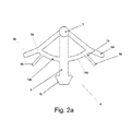
- the release lever mechanism (4) and the functioning of the release lever assembly in the terminal housing are illustrated in figures 2a and 2b .
- the release lever mechanism (4) comprises a cylindrical pivot member (5) used to mount the release lever mechanism (4) with the screwless terminal housing or with the plastic housing of a socket unit or the like depending on the design and space constraints.
- the cylindrical pivot member (5) serves as a pivot point for the release lever mechanism (4).
- Release arms (6a, 6b) are provided to extend from the pivot member (5) on opposite sides in a manner such that they are positioned to actuate the screwless terminal spring (3) when a main arm (8) of the release lever mechanism (4) is laterally pushed.
- the main arm (8) is pivoted since it extends perpendicularly downwardly from said pivot member (5), and it provides the necessary motion to the release arms (6a, 6b) when actuated.
- the terminal spring (3) in connection with the first release arm (6a) is actuated by the first release arm (6a) to release the conductor housed in its conductor housing (11a) when the main arm (8) is pushed in the positive 'x' direction.
- the terminal spring (3) in connection with the second release arm (6b) is actuated by the second release arm (6b) to release the conductor housed in the conductor housing (11 b) when the main arm (8) is pushed in the opposite direction.
- a first arcuate support (14a) extends from the main arm (8) to provide structural rigidity to the first release arm (6a).
- a second arcuate support (14b) extends from the main arm (8) to provide structural rigidity to the second release arm (6b).
- a second return arm (9b) extending from the second arcuate support (14b) is depressed against the plastic housing when the main arm (8) is pushed in the positive 'x' direction to facilitate the release of the conductor from the housing (11a).
- a first return arm (9a) extending from the first arcuate support (14a) is depressed against the plastic housing when the main arm (8) is pushed in the opposite direction to facilitate the release of the conductor from the housing (11 b).
- FIGs 1 a and 1 b shows the de-actuated and actuated positions of the release lever assembly.
- the first and second return arms (9b, 9a) are formed with respective hinge-like portions (7b, 7a) to give flexibility to return to the rest position about this point.
- a main arm grip (10) is provided partially on the main arm (8) to offer a gripping surface when the main arm is being pushed.
- the main arm (8) may be pushed manually or by using a tool, such as a screwdriver, or any other appropriate tool.
- the above construction of the terminal housing and release lever assembly facilitates release of conductors on substantially opposite sides of the terminal independently of each other using a single release lever assembly.
- the release lever assembly (4) described above is mounted on the plastic housing (2) of the socket assembly as illustrated in figure 3 .
- the release lever assembly can also be mounted to the screwless terminal as shown in figure 4b .
- the cylindrical pivot member is snapped into recesses (13) formed in the terminal housing (1) as clearly shown in figure 4a . These recesses (13) expand and hold the cylindrical pivot member (5).
- the screwless terminal assembly in accordance with the invention is illustrated separately in figures 5a and 5b .
- the construction of the screwless terminal assembly is such that the terminal housings are on substantially opposite sides on the same plane separated by an angle of about 140° to 170°, preferably about 160° as shown in figure 5a .
- This angular orientation of the terminal housings enables ease of insertion of conductors and drastically reduces the stresses, which is usually caused due to bending of the conductor.
- a single terminal is sufficient to receive two conductors on the same plane.
- the terminal assembly comprises at least two tubular conductor housings (11a, 11 b) spaced apart from each other at an angle of preferably 160° as mentioned above.
- the tubular housing construction of the terminal assembly is illustrated in figure 5c .
- the tubular housing configuration enables efficient insertion, positioning and seating of the conductors, both flexible and stranded, inside the terminal housing.
- the terminal housing (1) comprises a sub assembly feature (15) adjacent to each of the tubular conductor housings (11a, 11b).
- the feature (15) is assembled after positioning the Terminal Spring (3) inside the terminal housing.
- the sub assembly feature (15) secures the Terminal spring with Terminal housing.
- the tubular conductor housings (11a, 11 b) have a chamfer shaped entry portion (16) to facilitate ease of entry of the conductor.
- a recess (17) is provided for aiding the assembly of Scewless terminal spring (3) into terminal housing (1).
- the arms (20) are flexed outwards & pushed inside the recess (17) on both sides.
- a slot (18) for knife-edge contact with a rail is provided on a protrusion (19) in the terminal housing (1). This slot (18) serves as an integrated feature in the terminal housing for a mechanical connection with the rail.
- the terminal resilient member preferably a spring (3) is illustrated in figure 6 .
- the spring (3) is generally of a single piece construction made of suitable material with a flexible bend on both sides to provide the spring action. Locators (19) are provided in the spring (3) to be positioned and locked, preferably fitted in the bent assembly feature (15 of fig 5b ) of the terminal housing. An arm (20) is provided in each of the flexible bend of the spring (3) to press the conductor against the terminal housing, thus maintaining contact pressure.
- a bent arm (21) is provided in each of the flexible bend of the spring (3), which will become depressed by the release lever during a releasing operation of the conductor.
- a spring locating slot (22) is provided on the terminal housing as shown in figure 7 . The spring locating slot (22) is configured to securely latch the spring onto the terminal housing (1).
- FIG 8 A fully assembled sectional view of the terminal housing assembly (1) is shown in figure 8 , where the release lever (4) is in the actuated position.
- the release arm (6a) In its actuated position, the release arm (6a) is configured to displace the bent arm (21) portion of the terminal spring (3) from its normal position to facilitate the release of the conductor from the tubular conductor housing (11a).
- the Resilient property of terminal spring (3) will bring it back to its original position once the force on the release lever (4) is removed.
- the resilient arm (21) of terminal spring (3) forces the release arm (6a) of the release lever (4) to bring it back to its original position.
- the Release lever (4) is free to play inside the Pocket (23) when both conductors are inserted in to tubular terminal housing (11 a & 11 b).
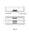
- the screwless terminal assembly of the instant invention is designed such that it eliminates the need for two separate terminals on the two ends for each pole of the socket outlet.
- Figure 9 shows the bi directional conductor entry screwless terminal of the invention as provided for a socket. The provision for an input conductor and a conductor for looping are provided on the same terminal assembly (1).
- a single screwless terminal assembly for each of the live, earth and neutral poles of the socket outlet is provided.
- Figure 10a shows the isometric view of the terminal assembly integrated with a rail (24).
- the rail (24) is pushed into the slot (18) in the terminal housing as illustrated in figure 10b .
- Figure 10c shows the different views of the terminal housing (1) integrated with the rail (24).
- the live and neutral contacts (L, N) are positioned on the rail as shown, each terminal having a plug pin recess (25) therein.
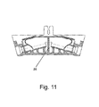
- a stopping means preferably in the form of a projection (26) is provided on the terminal as shown in figure 11 to prevent the conductor from entering beyond a certain limit to ensure that an extra length of the conductor does not interfere with other unintended parts and functions.
Landscapes
- Connections Arranged To Contact A Plurality Of Conductors (AREA)
- Details Of Connecting Devices For Male And Female Coupling (AREA)
Applications Claiming Priority (1)
| Application Number | Priority Date | Filing Date | Title |
|---|---|---|---|
| IN2084CH2010 | 2010-07-21 |
Publications (1)
| Publication Number | Publication Date |
|---|---|
| EP2410611A1 true EP2410611A1 (de) | 2012-01-25 |
Family
ID=44720208
Family Applications (1)
| Application Number | Title | Priority Date | Filing Date |
|---|---|---|---|
| EP11174182A Withdrawn EP2410611A1 (de) | 2010-07-21 | 2011-07-15 | Schraubenlose Endgeräteanordnung |
Country Status (2)
| Country | Link |
|---|---|
| EP (1) | EP2410611A1 (de) |
| CN (1) | CN102347533B (de) |
Cited By (2)
| Publication number | Priority date | Publication date | Assignee | Title |
|---|---|---|---|---|
| WO2014075967A1 (de) * | 2012-11-13 | 2014-05-22 | Wago Verwaltungsgesellschaft Mbh | Anschlussklemme |
| EP2800206A1 (de) * | 2013-04-30 | 2014-11-05 | Fabrication d'Applications et de Réalisations Electroniques | Elektrischer Anschluss mit Kontaktstreifen |
Citations (7)
| Publication number | Priority date | Publication date | Assignee | Title |
|---|---|---|---|---|
| DE7613091U1 (de) * | 1976-04-27 | 1976-08-26 | Fa. Hermann Kleinhuis, 5880 Luedenscheid | Schraubenlose Klemme zur Stromübertragung von elektrischen Leitern |
| DE2609291A1 (de) * | 1976-03-06 | 1977-09-15 | Kleinhuis Fa H | Schraubenlose anschlussklemme zur stromuebertragung von elektrischen leitern |
| DE3204844A1 (de) * | 1982-02-11 | 1983-08-18 | OBO Bettermann oHG, 5750 Menden | Schraubenlose anschlussklemme fuer elektrische, insbesondere flexible leiter |
| EP0833408A2 (de) * | 1996-09-27 | 1998-04-01 | Weidmüller Interface GmbH & Co. | Stromschiene mit Buchsen-Steckverbinder |
| DE19949387A1 (de) * | 1999-10-13 | 2001-05-31 | Electro Terminal Gmbh | Kontaktteil für Anschlussklemme |
| US20020076972A1 (en) * | 2000-11-03 | 2002-06-20 | Moret Codina Maria Cristina | Unit for connecting conductors to terminals |
| DE10103187A1 (de) * | 2001-01-24 | 2002-07-25 | Wago Verwaltungs Gmbh | Schieberbetätigte Klemme |
Family Cites Families (1)
| Publication number | Priority date | Publication date | Assignee | Title |
|---|---|---|---|---|
| CN2535934Y (zh) * | 2002-04-18 | 2003-02-12 | 江门市江海区汇聪电器厂 | 双孔双向导线连接无螺纹端子 |
-
2011
- 2011-07-15 CN CN201110206308.8A patent/CN102347533B/zh not_active Expired - Fee Related
- 2011-07-15 EP EP11174182A patent/EP2410611A1/de not_active Withdrawn
Patent Citations (7)
| Publication number | Priority date | Publication date | Assignee | Title |
|---|---|---|---|---|
| DE2609291A1 (de) * | 1976-03-06 | 1977-09-15 | Kleinhuis Fa H | Schraubenlose anschlussklemme zur stromuebertragung von elektrischen leitern |
| DE7613091U1 (de) * | 1976-04-27 | 1976-08-26 | Fa. Hermann Kleinhuis, 5880 Luedenscheid | Schraubenlose Klemme zur Stromübertragung von elektrischen Leitern |
| DE3204844A1 (de) * | 1982-02-11 | 1983-08-18 | OBO Bettermann oHG, 5750 Menden | Schraubenlose anschlussklemme fuer elektrische, insbesondere flexible leiter |
| EP0833408A2 (de) * | 1996-09-27 | 1998-04-01 | Weidmüller Interface GmbH & Co. | Stromschiene mit Buchsen-Steckverbinder |
| DE19949387A1 (de) * | 1999-10-13 | 2001-05-31 | Electro Terminal Gmbh | Kontaktteil für Anschlussklemme |
| US20020076972A1 (en) * | 2000-11-03 | 2002-06-20 | Moret Codina Maria Cristina | Unit for connecting conductors to terminals |
| DE10103187A1 (de) * | 2001-01-24 | 2002-07-25 | Wago Verwaltungs Gmbh | Schieberbetätigte Klemme |
Cited By (2)
| Publication number | Priority date | Publication date | Assignee | Title |
|---|---|---|---|---|
| WO2014075967A1 (de) * | 2012-11-13 | 2014-05-22 | Wago Verwaltungsgesellschaft Mbh | Anschlussklemme |
| EP2800206A1 (de) * | 2013-04-30 | 2014-11-05 | Fabrication d'Applications et de Réalisations Electroniques | Elektrischer Anschluss mit Kontaktstreifen |
Also Published As
| Publication number | Publication date |
|---|---|
| CN102347533A (zh) | 2012-02-08 |
| CN102347533B (zh) | 2015-08-26 |
Similar Documents
| Publication | Publication Date | Title |
|---|---|---|
| EP2568539B1 (de) | Leiterverbindungswerkzeug und Relaiseinheit damit | |
| CN107278344B (zh) | 插入式电连接器 | |
| EP3633795B1 (de) | Verbindungsvorrichtung | |
| JP2015506576A (ja) | ボードマウント電気コネクタ | |
| CN106981748B (zh) | 电连接器 | |
| EP1635425B1 (de) | Verbindungsanschluss | |
| EP2930792A1 (de) | Steckverbinder für kable und leiterplatte | |
| JP2015511379A (ja) | 電気コネクタ接触端子 | |
| JP2015510242A (ja) | 電気コネクタのストレインリリーフ | |
| JP4291341B2 (ja) | 接続装置 | |
| CN108232848A (zh) | 电连接器 | |
| CN111989826A (zh) | 用于制造电气装置的模块系统和终端装置 | |
| JP6931223B2 (ja) | 端子、及び電気コネクタ | |
| JP3262198B2 (ja) | コネクタ | |
| EP2410611A1 (de) | Schraubenlose Endgeräteanordnung | |
| EP2675016B1 (de) | Elektrischer kontakt | |
| TWM539173U (zh) | 按壓開關接線裝置 | |
| JP2005353283A (ja) | コネクタ構造 | |
| JP4481161B2 (ja) | L型同軸ケーブル用リセプタクルコネクタ | |
| JP2011134458A (ja) | 電線対基板コネクタ | |
| TWI824844B (zh) | 連接裝置及電子裝置 | |
| JP2601193Y2 (ja) | 差込形接続端子 | |
| TWI607467B (zh) | 按壓開關接線裝置 | |
| US20220359998A1 (en) | Electrical Assembly with a Pluggable Connector Having a Through-Opening for a Receiving a Conductor Adapter | |
| JP2009187833A (ja) | 電線接続装置 |
Legal Events
| Date | Code | Title | Description |
|---|---|---|---|
| AK | Designated contracting states |
Kind code of ref document: A1 Designated state(s): AL AT BE BG CH CY CZ DE DK EE ES FI FR GB GR HR HU IE IS IT LI LT LU LV MC MK MT NL NO PL PT RO RS SE SI SK SM TR |
|
| AX | Request for extension of the european patent |
Extension state: BA ME |
|
| PUAI | Public reference made under article 153(3) epc to a published international application that has entered the european phase |
Free format text: ORIGINAL CODE: 0009012 |
|
| 17P | Request for examination filed |
Effective date: 20120720 |
|
| GRAP | Despatch of communication of intention to grant a patent |
Free format text: ORIGINAL CODE: EPIDOSNIGR1 |
|
| INTG | Intention to grant announced |
Effective date: 20150929 |
|
| STAA | Information on the status of an ep patent application or granted ep patent |
Free format text: STATUS: THE APPLICATION IS DEEMED TO BE WITHDRAWN |
|
| 18D | Application deemed to be withdrawn |
Effective date: 20160210 |