EP2410592A1 - Battery module - Google Patents
Battery module Download PDFInfo
- Publication number
- EP2410592A1 EP2410592A1 EP20110152875 EP11152875A EP2410592A1 EP 2410592 A1 EP2410592 A1 EP 2410592A1 EP 20110152875 EP20110152875 EP 20110152875 EP 11152875 A EP11152875 A EP 11152875A EP 2410592 A1 EP2410592 A1 EP 2410592A1
- Authority
- EP
- European Patent Office
- Prior art keywords
- porous film
- battery module
- housing
- valve
- vent opening
- Prior art date
- Legal status (The legal status is an assumption and is not a legal conclusion. Google has not performed a legal analysis and makes no representation as to the accuracy of the status listed.)
- Granted
Links
Images


Classifications
-
- H—ELECTRICITY
- H01—ELECTRIC ELEMENTS
- H01M—PROCESSES OR MEANS, e.g. BATTERIES, FOR THE DIRECT CONVERSION OF CHEMICAL ENERGY INTO ELECTRICAL ENERGY
- H01M50/00—Constructional details or processes of manufacture of the non-active parts of electrochemical cells other than fuel cells, e.g. hybrid cells
- H01M50/30—Arrangements for facilitating escape of gases
- H01M50/317—Re-sealable arrangements
-
- H—ELECTRICITY
- H01—ELECTRIC ELEMENTS
- H01M—PROCESSES OR MEANS, e.g. BATTERIES, FOR THE DIRECT CONVERSION OF CHEMICAL ENERGY INTO ELECTRICAL ENERGY
- H01M50/00—Constructional details or processes of manufacture of the non-active parts of electrochemical cells other than fuel cells, e.g. hybrid cells
- H01M50/30—Arrangements for facilitating escape of gases
- H01M50/342—Non-re-sealable arrangements
-
- H—ELECTRICITY
- H01—ELECTRIC ELEMENTS
- H01M—PROCESSES OR MEANS, e.g. BATTERIES, FOR THE DIRECT CONVERSION OF CHEMICAL ENERGY INTO ELECTRICAL ENERGY
- H01M50/00—Constructional details or processes of manufacture of the non-active parts of electrochemical cells other than fuel cells, e.g. hybrid cells
- H01M50/30—Arrangements for facilitating escape of gases
- H01M50/394—Gas-pervious parts or elements
-
- H—ELECTRICITY
- H01—ELECTRIC ELEMENTS
- H01M—PROCESSES OR MEANS, e.g. BATTERIES, FOR THE DIRECT CONVERSION OF CHEMICAL ENERGY INTO ELECTRICAL ENERGY
- H01M10/00—Secondary cells; Manufacture thereof
- H01M10/05—Accumulators with non-aqueous electrolyte
- H01M10/052—Li-accumulators
-
- H—ELECTRICITY
- H01—ELECTRIC ELEMENTS
- H01M—PROCESSES OR MEANS, e.g. BATTERIES, FOR THE DIRECT CONVERSION OF CHEMICAL ENERGY INTO ELECTRICAL ENERGY
- H01M50/00—Constructional details or processes of manufacture of the non-active parts of electrochemical cells other than fuel cells, e.g. hybrid cells
- H01M50/30—Arrangements for facilitating escape of gases
- H01M50/342—Non-re-sealable arrangements
- H01M50/3425—Non-re-sealable arrangements in the form of rupturable membranes or weakened parts, e.g. pierced with the aid of a sharp member
-
- Y—GENERAL TAGGING OF NEW TECHNOLOGICAL DEVELOPMENTS; GENERAL TAGGING OF CROSS-SECTIONAL TECHNOLOGIES SPANNING OVER SEVERAL SECTIONS OF THE IPC; TECHNICAL SUBJECTS COVERED BY FORMER USPC CROSS-REFERENCE ART COLLECTIONS [XRACs] AND DIGESTS
- Y02—TECHNOLOGIES OR APPLICATIONS FOR MITIGATION OR ADAPTATION AGAINST CLIMATE CHANGE
- Y02E—REDUCTION OF GREENHOUSE GAS [GHG] EMISSIONS, RELATED TO ENERGY GENERATION, TRANSMISSION OR DISTRIBUTION
- Y02E60/00—Enabling technologies; Technologies with a potential or indirect contribution to GHG emissions mitigation
- Y02E60/10—Energy storage using batteries
Definitions
- the described technology relates generally to a battery module.
- a rechargeable battery can be discharged and recharged.
- a low-capacity rechargeable battery has been used for a small-sized portable electronic device such as a mobile phone, a laptop computer, or a camcorder.
- a large-capacity battery has been prevalently used as a power supply for driving a motor of a hybrid vehicle, or the like.
- the above-mentioned high power rechargeable battery is configured as a large-capacity rechargeable battery by connecting a plurality of rechargeable batteries in series to be able to drive a motor for devices requiring large power, such as an electric vehicle, etc.
- one large-capacity rechargeable battery is configured from a plurality of rechargeable batteries generally connected to each other in series and the rechargeable battery may be a cylindrical shape or a quadrangular shape.
- a rechargeable battery includes an exhaust member that opens when the internal pressure is increased. This is to prevent the explosion of the rechargeable battery due to the increase in the internal pressure of the rechargeable battery.
- the gas discharged from the rechargeable battery should be rapidly discharged to the outside. If gas in the rechargeable battery is not rapidly discharged to the outside, the rechargeable battery may explode or ignite. In order to rapidly discharge the gas in the rechargeable battery, the pressure in the housing of the battery module should be sufficiently low. However, when the rechargeable batteries are positioned in the closed and sealed housing, the pressure in the housing is not sufficiently low to rapidly discharge gas and the rechargeable battery may explode.
- the described technology provides a battery module with an improved safety.
- a housing surrounding a battery module has a vent opening that is provided with a porous film, thereby making it possible to stably discharge gas generated from the inside of the battery module.
- An exemplary embodiment of the present invention provides a battery module including: a plurality of rechargeable batteries, a housing configured to receive the rechargeable batteries, wherein the housing has a vent opening; and a valve configured to close the vent opening, wherein the valve includes a porous film with pores having a diameter larger than that of gas molecules, in particular gas molecules such as nitrogen (N 2 ), hydrogen (H 2 ), carbon monoxide (CO), and methane (CH 4 ), and smaller than that of water particles.
- gas molecules such as nitrogen (N 2 ), hydrogen (H 2 ), carbon monoxide (CO), and methane (CH 4 ), and smaller than that of water particles.
- the porous film may include polytetrafluoroethylene (PTFE).
- PTFE polytetrafluoroethylene
- the porous film may include a material selected from the group consisting of perfluoroalkoxy polymer (PFA), fluorinated ethylene propylene (FEP), ethylene chlorotrifluoroethylene copolymer (ECTFE), ethylene tetrafluoroethylene (ETFE), polyvinylidene fluoride (PVDF), and combinations thereof.
- PFA perfluoroalkoxy polymer
- FEP fluorinated ethylene propylene
- ECTFE ethylene chlorotrifluoroethylene copolymer
- ETFE ethylene tetrafluoroethylene
- PVDF polyvinylidene fluoride
- the porous film may have a notch.
- the valve may further include a supporting film stacked on the porous film.
- the supporting film may have a notch.
- the supporting film may have a strength greater than that of the porous film, and may be configured to pass gas molecules, in particular gas molecules such as nitrogen (N 2 ), hydrogen (H 2 ), carbon monoxide (CO), and methane (CH 4 ), therethrough.
- the housing includes a body having an inner space and a cover coupled with the body, and the valve may be installed on the cover. In one embodiment, the valve may be installed on the body.
- the valve may further include a protective bar that crosses the vent opening and contacts the porous film.
- the protective bar may have a wedge portion contacting the porous film, wherein the wedge portion has a reduced sectional area toward the end thereof contacting the porous film.
- the battery module may further include a supporting member having a ring shape to closely attach the porous film to the housing.
- the supporting member may have an opening, and the supporting member may further include a protrusion having a wedge shape and protruding toward the porous film along a periphery of the opening of the supporting member.
- a groove may be formed under the vent opening and the porous film, and the supporting member may be inserted into the groove.
- a protrusion having a wedge shape and protruding toward the porous film may be formed along the periphery of the vent opening.
- a battery module including a plurality of rechargeable batteries, a housing configured to receive the rechargeable batteries, wherein the housing has a vent opening; and a valve configured to close the vent opening and to be ruptured at a rupture pressure, wherein the valve is configured to pass gas molecules through the valve and block liquid molecules.
- the valve may have a notch.
- FIG. 1 is a perspective view showing a battery module according to a first exemplary embodiment of the present invention
- FIG. 2 is a cross-sectional view taken along the line II-II of FIG. 1 ;
- FIG. 3 is a perspective view showing a vent member (e.g., a vent) installed in a housing according to a second exemplary embodiment of the present invention
- FIG. 4 is a cross-sectional view taken along the line IV-IV of FIG. 3 ;
- FIG. 5 is a cross-sectional view showing a vent member (e.g., a vent) installed in a housing in a battery module according to a third exemplary embodiment of the present invention
- FIG. 6 is a cross-sectional view showing a vent member (e.g., a vent) installed in a housing in a battery module according to a fourth exemplary embodiment of the present invention.
- a vent member e.g., a vent
- FIG. 7 is a cross-sectional view showing a vent member (e.g., a vent) installed in a housing in a battery module according to a fifth exemplary embodiment of the present invention.
- a vent member e.g., a vent
- FIG. 8 is a cross-sectional view taken along the line VIII-VIII of FIG. 7 ;
- FIG. 9 is a perspective view showing a battery module according to a sixth exemplary embodiment of the present invention.
- FIG. 10 is a cross-sectional view taken along the line X-X of FIG. 9 .
- FIG. 1 is a perspective view showing a battery module according to a first exemplary embodiment of the present invention and FIG. 2 is a cross-sectional view taken along the line II-II of FIG. 1 .
- a battery module 101 includes a plurality of rechargeable batteries 120, a housing 110 in which the rechargeable batteries 120 are accommodated, and a valve member (e.g., a valve) installed in a vent hole (or a vent opening) 114a of the housing 110.
- a valve member e.g., a valve
- a plurality of rechargeable batteries 120 are installed in the housing 110.
- the rechargeable battery 120 will be described as a lithium ion secondary battery having a generally quadrangular shape.
- the present invention is not limited thereto, and embodiments of the present invention may be applied to batteries of various types such as a lithium polymer battery or a cylindrical battery, etc.
- the rechargeable battery 120 includes a positive terminal 123, a negative terminal 124, and an exhaust member 121 that is opened at a rupture pressure (e.g., predetermined pressure) to discharge gas.
- the exhaust member 121 is ruptured at the rupture pressure (e.g., predetermined pressure) when the pressure in the rechargeable battery 120 is increased, to provide a path that can discharge the gas in the rechargeable battery 120 to the outside.
- the plurality of rechargeable batteries 120 are installed in the housing 110 and connected in series by a connection member 125.
- the housing 110 may be formed in a rectangular parallelepiped shape and includes a body 112 having an inner space and a cover 114 coupled with the body 112.
- the housing 110 is formed to have a closed and sealed structure and the rechargeable batteries 120 are cooled by cooling the housing 110.
- a vent hole (or a vent opening) 114a may be formed on the cover 114 and may have a circular sectional shape.
- a valve member e.g., a valve
- the porous film may be made of Teflon®-based resin, for example, polytetrafluoroethylene (PTFE) (Teflon® is a registered trademark of E. I. Du Pont De Nemours and Company).
- the porous film may be made of perfluoroalkoxy polymer (PFA), fluorinated ethylene propylene (FEP), ethylene chlorotrifluoroethylene copolymer (ECTFE), ethylenete trafluoroethylene (ETFE), polyvinylidene fluoride (PVDF), or a combination thereof.
- PFA perfluoroalkoxy polymer
- FEP fluorinated ethylene propylene
- ECTFE ethylene chlorotrifluoroethylene copolymer
- ETFE ethylenete trafluoroethylene
- PVDF polyvinylidene fluoride
- the porous film 130 is formed with pores 131 having a diameter larger than that of gas molecules and smaller than that of water particles. Therefore, gas molecules such as nitrogen (N 2 ), hydrogen (H 2 ), carbon monoxide (CO), and methane (CH 4 ) may pass through the porous film 130 but water particles may not, thereby making it possible to discharge the gas in the housing 110 to the outside and prevent liquid, etc., from being infiltrated (or infiltrating) into the housing 110 from the outside.
- gas molecules such as nitrogen (N 2 ), hydrogen (H 2 ), carbon monoxide (CO), and methane (CH 4 ) may pass through the porous film 130 but water particles may not, thereby making it possible to discharge the gas in the housing 110 to the outside and prevent liquid, etc., from being infiltrated (or infiltrating) into the housing 110 from the outside.
- the exhaust member 121 e.g., gas discharging unit
- the first exemplary embodiment can prevent (or substantially prevent) water or foreign materials outside the housing 110 from being infiltrated (or infiltrating) into the housing 110.
- the porous film 130 may be ruptured at a rupture pressure (e.g., predetermined pressure), wherein the rupture pressure of the porous film 130 may be determined according to the thickness of the porous film 130.
- a rupture pressure e.g., predetermined pressure
- the porous film 130 may be broken to rapidly discharge the gas in the housing 110 to the outside.
- the gas When the internal pressure of the housing 110 is below the rupture pressure of the porous film 130, the gas may be discharged through the porous film 130 without breaking the porous film 130. However, when the internal pressure thereof is largely increased, there is a need to discharge a large amount of gas at one time. As a result, the porous film 130 is broken to smoothly discharge gas.
- FIG. 3 is a perspective view showing a vent member (e.g., a vent) installed in a housing according to a second exemplary embodiment of the present invention and FIG. 4 is a cross-sectional view taken along the line IV-IV of FIG. 3 .
- a vent member e.g., a vent
- a battery module according to the second exemplary embodiment is substantially the same as the battery module according to the first exemplary embodiment except for the structure of the valve member (e.g., the valve) and therefore, repeated description of the same components will be omitted.
- the cover 214 of the housing of the battery module according to the second exemplary embodiment is provided with a vent hole (or a vent opening) 214a and a valve member (e.g., a valve) to close the vent hole (or the vent opening) 214a.
- the vent hole (or the vent opening) 214a may be formed in a generally quadrangular sectional shape and the valve member (e.g., the valve) may be attached below the vent hole (or the vent opening) 214a.
- the valve member (e.g., the valve) includes the porous film 230, which is provided with pores having a diameter larger than that of gas molecules and smaller than that of water particles.
- the porous film 230 may be made of Teflon®-based resin, for example, polytetrafluoroethylene (PTFE).
- a groove 214b is formed under the vent hole (or the vent opening) 214a, wherein the groove 214b is formed, for example, continuously along the periphery (e.g., circumferential direction) of the vent hole (or the vent opening) 214a.
- the porous film 230 may be inserted into the groove 214b, and a supporting member 240 closely attaching the porous film 230 to the groove 214b may be installed under the porous film 230.
- the supporting member 240 and/or the groove 214b may have a rectangular or any other suitable shape to conform to the shape of the vent hole (or the vent opening) 214a.
- the supporting member 240 is formed in a ring shape where an opening 241 is formed at the center thereof. The supporting member 240 may be inserted into the groove 214b to support the porous film 230 by contacting the edge of the porous film 230.
- the porous film 230 is formed with a notch 231 to be ruptured at a rupture pressure (e.g., predetermined pressure) to discharge gas from the housing to the outside through the porous film 230.
- a rupture pressure e.g., predetermined pressure
- the notch 231 may be ruptured to discharge gas to the outside.
- the support member 240 fixes (or secures) the edge of the porous film 230
- the notch 231 may be easily broken at the rupture pressure (e.g., predetermined pressure).
- the porous film 230 may be fused to the cover 214, such that when the pressure is increased, the notch 231 is not broken but the fused portion may be separated. When the fused portion is separated, the opened area may be small and may not rapidly discharge gas.
- the supporting member 240 is installed, the notch 231 is more stably broken, thereby making it possible to rapidly discharge gas.
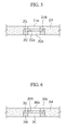
- FIG. 5 is a cross-sectional view showing a vent member (e.g., a vent) installed in a housing in a battery module according to a third exemplary embodiment of the present invention.
- a vent member e.g., a vent
- the battery module according to the third exemplary embodiment is substantially the same as the battery module according to the second exemplary embodiment except for the structure of the valve member (e.g., the valve) and therefore, repeated description of the same components will be omitted.
- the cover 214 of the battery module according to the third exemplary embodiment is provided with a vent hole (or a vent opening) 214a and is installed with a valve member (e.g., a valve) to cover the vent hole (or the vent opening) 214a.
- a valve member e.g., a valve
- the valve member (e.g., the valve) includes a porous film 251, wherein the porous film 251 is formed with pores having a diameter larger than that of gas molecules and a diameter smaller than that of water particles.
- the porous film 251 may be made of Teflon®-based resin, for example, polytetrafluoroethylene (PTFE).
- a groove 214b may be formed under the vent hole (or the vent opening) 214a, wherein the groove 214b is formed, for example, continuously along the periphery (e.g., circumferential direction) of the vent hole (or the vent opening) 214a.
- the porous film 251 may be inserted into the groove 214b and a supporting member 252 closely attaching the porous film 251 to the groove 214b may be installed under the porous film 251. Therefore, the porous film 251 may be positioned between the cover 214 and the supporting member 252.
- the supporting member 252 and/or the groove 214b may have a rectangular or any other suitable shape to conform to the shape of the vent hole (or the vent opening) 214a.
- the supporting member 252 is formed in a ring shape where an opening 252b is formed at the center thereof, and the supporting member 252 is inserted into the groove 214b to support the porous film 251 by contacting the edge of the porous film 251.
- the upper surface of the supporting member 252 may be provided with a protrusion 252a, wherein the protrusion 252a has a reduced sectional area towards an end thereof to sharply protrude in a wedge shape.
- the protrusion 252a may be formed, for example, continuously along the periphery (e.g., circumference) of the opening 252b and the protrusion 252a presses the porous film 251.
- Gas may be discharged from the housing 110 to the outside through the porous film 251 and when the internal pressure of the housing is increased at a rapid speed, a portion of the porous film 251 contacting the protrusion 252a may be broken to discharge gas to the outside.
- a rupture pressure e.g., predetermined pressure
- the porous film 251 may be fused to the cover 214, such that when the pressure is increased, the porous film 251 is not broken but the fused portion may be separated. When the fused portion is separated, the opened area may be small and may not rapidly discharge gas. However, when the supporting member 252 is installed, the porous film 251 may be broken, thereby making it possible to rapidly discharge gas.
- FIG. 6 is a cross-sectional view showing a vent member (e.g., a vent) installed in a housing in a battery module according to a fourth exemplary embodiment of the present invention.
- a vent member e.g., a vent
- the battery module according to the fourth exemplary embodiment is substantially the same as the battery module according to the second exemplary embodiment except for the structure of the valve member (e.g., the valve) and therefore, repeated description of the same components will be omitted.
- a cover 264 of the housing of the battery module according to the fourth exemplary embodiment is provided with a vent hole (or a vent opening) 264a and is installed with a valve member (e.g., a valve) to cover the vent hole (or the vent opening) 264a.
- a valve member e.g., a valve
- the valve member (e.g., the valve) includes a porous film 261, wherein the porous film 261 is formed with pores having a diameter larger than that of gas molecules and a diameter smaller than that of water particles.
- the porous film 261 may be made of Teflon®-based resin, for example, polytetrafluoroethylene (PTFE).
- a groove 264c may be formed under a vent hole (or a vent opening) 264a, wherein the groove 264c is formed, for example, continuously along the periphery (e.g., circumferential direction) of the vent hole (or the vent opening) 264a.
- the porous film 261 may be inserted into the groove 264c and a supporting member 240 closely attaching the porous film 261 to the groove 264c may be installed under the porous film 261.
- the supporting member 240 and/or the groove 264c may have a rectangular or any other suitable shape to conform to the shape of the vent hole (or the vent opening) 264a.
- the supporting member 240 is formed in a ring shape where an opening 241 is formed at the center thereof. The supporting member 240 may be inserted into the groove 264c to support the porous film 261 by contacting the edge of the porous film 261.
- the periphery (e.g., circumference) of the vent hole (or the vent opening) 264a may be provided with a protrusion 264b protruded toward the porous film 261, wherein the protrusion 264b has a reduced sectional area towards an end thereof to sharply protrude in a wedge shape.
- the protrusion 264b is formed, for example, continuously along the periphery (e.g., circumference) of the groove 264c and the protrusion 264b presses the porous film 261.
- Gas may be discharged from the housing 110 to the outside through the porous film 261, and when the internal pressure of the housing 110 is increased at a rapid speed, a portion of the porous film 261 contacting the protrusion 264b may be broken to discharge gas to the outside.
- a rupture pressure e.g., predetermined pressure
- the porous film 261 may be fused to the cover 264, such that when the pressure is increased, the porous film 261 is not broken but the fused portion may be separated. When the fused portion is separated, the opened area may be small and may not rapidly discharge gas. However, when the supporting member 240 is installed, the porous film 261 may be broken, thereby making it possible to rapidly discharge gas.
- FIG. 7 is a cross-sectional view showing a vent member (e.g., a vent) installed in a housing in a battery module according to a fifth exemplary embodiment of the present invention and FIG. 8 is a cross-sectional view taken along the line VIII-VIII of FIG. 7 .
- a vent member e.g., a vent
- the battery module according to the fifth exemplary embodiment is substantially the same as the battery module according to the first exemplary embodiment except for the structure of the valve member (e.g., the valve) and therefore, repeated description of the same components will be omitted.
- the cover 314 of the battery module according to the fifth exemplary embodiment is provided with a vent hole (or the vent opening) 314a and may be installed with a valve member (e.g., the valve) 330 to cover the vent hole (or the vent opening) 314a.
- a valve member e.g., the valve
- the valve member (e.g., the valve) 330 includes a porous film 331 which may be made of Teflon®-based resin and a supporting film 332 stacked on the porous film 331 and the supporting film 332 is located on the porous film 331.
- the porous film 331 is formed with pores having a diameter larger than that of gas molecules and a diameter smaller than that of water particles, and the supporting film 332 is formed to have a structure capable of passing gas.
- the supporting film 332 may be formed to have strength greater than that of the porous film 331 to protect the porous film 331 from external impact.
- the supporting film 332 is formed with a notch 335 to be open at a rupture pressure (e.g., predetermined pressure).
- Installing the supporting film 332 as in the fifth exemplary embodiment can prevent the porous film 331 from being ruptured due to external impact.
- the supporting film 332 may be formed with the notch 335, it can more easily set the opening pressure of the valve member (e.g., the valve) 330. Gas may be discharged from the housing to the outside through the porous film 331 and when the internal pressure of the housing is increased at a rapid speed, the notch 335 may be broken to discharge gas to the outside.
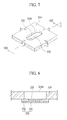
- FIG. 9 is a perspective view showing a battery module according to a sixth exemplary embodiment of the present invention and FIG. 10 is a cross-sectional view taken along the line X-X of FIG. 9 .
- a battery module 102 includes a plurality of rechargeable batteries, a housing 410 in which the rechargeable batteries are contained, and a valve member (e.g., a valve) installed in a vent hole (or a vent opening) 412a formed in the housing 410.
- a valve member e.g., a valve
- the housing 410 may be formed in a rectangular parallelepiped shape and includes a body 412 having an inner space and a cover 414 coupled with the body 412.
- the body 412 is formed with the vent hole (or the vent opening) 412a, wherein the vent hole (or the vent opening) 412a may be formed on a side of the body 412 and may have a generally quadrangular shape.
- the valve member (e.g., the valve) includes a protective bar 450 that is installed to close the vent hole (or the vent opening) 412a, and installed contacting the porous film 430.
- the porous film 430 may be made of Teflon®-based resin, for example, polytetrafluoroethylene (PTFE).
- PTFE polytetrafluoroethylene
- the porous film 430 is formed with pores having a diameter larger than that of gas molecules and a diameter smaller than that of water particles. Therefore, gas molecules may pass through the porous film 430 but water particles may not, thereby making it possible to discharge the gas in the housing 410 to the outside and prevent liquid from infiltrating into the housing from the outside.
- the plurality of protective bars 450 are installed to cross the vent hole (or the vent opening) 412a in a lattice shape intersecting with each other.
- the protective bars 450 serve to prevent (or substantially prevent) the porous film 430 from being broken due to external impact or vibrations.
- the portion contacting the porous film 430 may include a wedge portion 451 sharply formed by reducing the sectional area towards an end thereof.
- the wedge portion 451 presses the porous film 430 and when the internal pressure of the housing is rapidly increased, the porous film 430 may be broken by the wedge portion 451.
Landscapes
- Chemical & Material Sciences (AREA)
- Chemical Kinetics & Catalysis (AREA)
- Electrochemistry (AREA)
- General Chemical & Material Sciences (AREA)
- Gas Exhaust Devices For Batteries (AREA)
Abstract
Description
- The described technology relates generally to a battery module.
- Unlike a primary battery that is not designed to be recharged, a rechargeable battery can be discharged and recharged. A low-capacity rechargeable battery has been used for a small-sized portable electronic device such as a mobile phone, a laptop computer, or a camcorder. A large-capacity battery has been prevalently used as a power supply for driving a motor of a hybrid vehicle, or the like.
- Recently, a high-power rechargeable battery using a non-aqueous electrolyte and having a high energy density has been developed. The above-mentioned high power rechargeable battery is configured as a large-capacity rechargeable battery by connecting a plurality of rechargeable batteries in series to be able to drive a motor for devices requiring large power, such as an electric vehicle, etc.
- In addition, one large-capacity rechargeable battery is configured from a plurality of rechargeable batteries generally connected to each other in series and the rechargeable battery may be a cylindrical shape or a quadrangular shape.
- A rechargeable battery includes an exhaust member that opens when the internal pressure is increased. This is to prevent the explosion of the rechargeable battery due to the increase in the internal pressure of the rechargeable battery.
- The gas discharged from the rechargeable battery should be rapidly discharged to the outside. If gas in the rechargeable battery is not rapidly discharged to the outside, the rechargeable battery may explode or ignite. In order to rapidly discharge the gas in the rechargeable battery, the pressure in the housing of the battery module should be sufficiently low. However, when the rechargeable batteries are positioned in the closed and sealed housing, the pressure in the housing is not sufficiently low to rapidly discharge gas and the rechargeable battery may explode.
- For example, since the pressure in the housing is increased after the exhaust member of one rechargeable battery is opened, gas is not rapidly discharged because the exhaust members of the other rechargeable batteries are also opened in this state, causing increased internal pressure such that the rechargeable battery may explode.
- The above information disclosed in this Background section is only for enhancement of understanding of the background of the described technology and therefore it may contain information that does not form part of the prior art that is known to a person of ordinary skill in the art.
- The described technology provides a battery module with an improved safety.
- According to aspects of embodiments of the present invention, a housing surrounding a battery module has a vent opening that is provided with a porous film, thereby making it possible to stably discharge gas generated from the inside of the battery module.
- An exemplary embodiment of the present invention provides a battery module including: a plurality of rechargeable batteries, a housing configured to receive the rechargeable batteries, wherein the housing has a vent opening; and a valve configured to close the vent opening, wherein the valve includes a porous film with pores having a diameter larger than that of gas molecules, in particular gas molecules such as nitrogen (N2), hydrogen (H2), carbon monoxide (CO), and methane (CH4), and smaller than that of water particles.
- The porous film may include polytetrafluoroethylene (PTFE).
- The porous film may include a material selected from the group consisting of perfluoroalkoxy polymer (PFA), fluorinated ethylene propylene (FEP), ethylene chlorotrifluoroethylene copolymer (ECTFE), ethylene tetrafluoroethylene (ETFE), polyvinylidene fluoride (PVDF), and combinations thereof.
- In one embodiment, the porous film may have a notch.
- The valve may further include a supporting film stacked on the porous film. In one embodiment, the supporting film may have a notch. The supporting film may have a strength greater than that of the porous film, and may be configured to pass gas molecules, in particular gas molecules such as nitrogen (N2), hydrogen (H2), carbon monoxide (CO), and methane (CH4), therethrough.
- In one embodiment, the housing includes a body having an inner space and a cover coupled with the body, and the valve may be installed on the cover. In one embodiment, the valve may be installed on the body.
- The valve may further include a protective bar that crosses the vent opening and contacts the porous film. In one embodiment, the protective bar may have a wedge portion contacting the porous film, wherein the wedge portion has a reduced sectional area toward the end thereof contacting the porous film.
- The battery module may further include a supporting member having a ring shape to closely attach the porous film to the housing. The supporting member may have an opening, and the supporting member may further include a protrusion having a wedge shape and protruding toward the porous film along a periphery of the opening of the supporting member. A groove may be formed under the vent opening and the porous film, and the supporting member may be inserted into the groove.
- In one embodiment, a protrusion having a wedge shape and protruding toward the porous film may be formed along the periphery of the vent opening.
- Another exemplary embodiment of the present invention provides a battery module including a plurality of rechargeable batteries, a housing configured to receive the rechargeable batteries, wherein the housing has a vent opening; and a valve configured to close the vent opening and to be ruptured at a rupture pressure, wherein the valve is configured to pass gas molecules through the valve and block liquid molecules. In one embodiment, the valve may have a notch.
-
FIG. 1 is a perspective view showing a battery module according to a first exemplary embodiment of the present invention; -
FIG. 2 is a cross-sectional view taken along the line II-II ofFIG. 1 ; -
FIG. 3 is a perspective view showing a vent member (e.g., a vent) installed in a housing according to a second exemplary embodiment of the present invention; -
FIG. 4 is a cross-sectional view taken along the line IV-IV ofFIG. 3 ; -
FIG. 5 is a cross-sectional view showing a vent member (e.g., a vent) installed in a housing in a battery module according to a third exemplary embodiment of the present invention; -
FIG. 6 is a cross-sectional view showing a vent member (e.g., a vent) installed in a housing in a battery module according to a fourth exemplary embodiment of the present invention; -
FIG. 7 is a cross-sectional view showing a vent member (e.g., a vent) installed in a housing in a battery module according to a fifth exemplary embodiment of the present invention; -
FIG. 8 is a cross-sectional view taken along the line VIII-VIII ofFIG. 7 ; -
FIG. 9 is a perspective view showing a battery module according to a sixth exemplary embodiment of the present invention; and -
FIG. 10 is a cross-sectional view taken along the line X-X ofFIG. 9 . - Exemplary embodiments of the present invention will be described more fully hereinafter with reference to the accompanying drawings. As those skilled in the art would realize, the described embodiments may be modified in various different ways, all without departing from the scope of the present invention. In addition, like reference numerals denote like elements in the specification and the accompanying drawings.
-
FIG. 1 is a perspective view showing a battery module according to a first exemplary embodiment of the present invention andFIG. 2 is a cross-sectional view taken along the line II-II ofFIG. 1 . - Referring to
FIGS. 1 and2 , abattery module 101 according to the first exemplary embodiment includes a plurality ofrechargeable batteries 120, ahousing 110 in which therechargeable batteries 120 are accommodated, and a valve member (e.g., a valve) installed in a vent hole (or a vent opening) 114a of thehousing 110. - A plurality of
rechargeable batteries 120 are installed in thehousing 110. By way of example, therechargeable battery 120 will be described as a lithium ion secondary battery having a generally quadrangular shape. However, the present invention is not limited thereto, and embodiments of the present invention may be applied to batteries of various types such as a lithium polymer battery or a cylindrical battery, etc. - The
rechargeable battery 120 includes apositive terminal 123, anegative terminal 124, and anexhaust member 121 that is opened at a rupture pressure (e.g., predetermined pressure) to discharge gas. Theexhaust member 121 is ruptured at the rupture pressure (e.g., predetermined pressure) when the pressure in therechargeable battery 120 is increased, to provide a path that can discharge the gas in therechargeable battery 120 to the outside. - The plurality of
rechargeable batteries 120 are installed in thehousing 110 and connected in series by aconnection member 125. - The
housing 110 may be formed in a rectangular parallelepiped shape and includes abody 112 having an inner space and acover 114 coupled with thebody 112. Thehousing 110 is formed to have a closed and sealed structure and therechargeable batteries 120 are cooled by cooling thehousing 110. - A vent hole (or a vent opening) 114a may be formed on the
cover 114 and may have a circular sectional shape. A valve member (e.g., a valve) may be installed to close the vent hole (or the vent opening) 114a and may be formed of theporous film 130. In one embodiment, the porous film may be made of Teflon®-based resin, for example, polytetrafluoroethylene (PTFE) (Teflon® is a registered trademark of E. I. Du Pont De Nemours and Company). In addition, the porous film may be made of perfluoroalkoxy polymer (PFA), fluorinated ethylene propylene (FEP), ethylene chlorotrifluoroethylene copolymer (ECTFE), ethylenete trafluoroethylene (ETFE), polyvinylidene fluoride (PVDF), or a combination thereof. - The
porous film 130 is formed withpores 131 having a diameter larger than that of gas molecules and smaller than that of water particles. Therefore, gas molecules such as nitrogen (N2), hydrogen (H2), carbon monoxide (CO), and methane (CH4) may pass through theporous film 130 but water particles may not, thereby making it possible to discharge the gas in thehousing 110 to the outside and prevent liquid, etc., from being infiltrated (or infiltrating) into thehousing 110 from the outside. - As such, according to an exemplary embodiment, when the exhaust member 121 (e.g., gas discharging unit) installed in the
rechargeable battery 120 is opened to discharge gas from the inside of therechargeable battery 120, the gas may be discharged from thehousing 110 through theporous film 130. In addition, the first exemplary embodiment can prevent (or substantially prevent) water or foreign materials outside thehousing 110 from being infiltrated (or infiltrating) into thehousing 110. - In addition, the
porous film 130 may be ruptured at a rupture pressure (e.g., predetermined pressure), wherein the rupture pressure of theporous film 130 may be determined according to the thickness of theporous film 130. When theexhaust members 121 mounted in the plurality ofrechargeable batteries 120 are opened to discharge gas from therechargeable batteries 120, the pressure in thehousing 110 is greatly increased instantly. In this case, theporous film 130 may be broken to rapidly discharge the gas in thehousing 110 to the outside. - When the internal pressure of the
housing 110 is below the rupture pressure of theporous film 130, the gas may be discharged through theporous film 130 without breaking theporous film 130. However, when the internal pressure thereof is largely increased, there is a need to discharge a large amount of gas at one time. As a result, theporous film 130 is broken to smoothly discharge gas. -
FIG. 3 is a perspective view showing a vent member (e.g., a vent) installed in a housing according to a second exemplary embodiment of the present invention andFIG. 4 is a cross-sectional view taken along the line IV-IV ofFIG. 3 . - Referring to
FIGS. 3 and 4 , a battery module according to the second exemplary embodiment is substantially the same as the battery module according to the first exemplary embodiment except for the structure of the valve member (e.g., the valve) and therefore, repeated description of the same components will be omitted. - The
cover 214 of the housing of the battery module according to the second exemplary embodiment is provided with a vent hole (or a vent opening) 214a and a valve member (e.g., a valve) to close the vent hole (or the vent opening) 214a. The vent hole (or the vent opening) 214a may be formed in a generally quadrangular sectional shape and the valve member (e.g., the valve) may be attached below the vent hole (or the vent opening) 214a. - The valve member (e.g., the valve) includes the
porous film 230, which is provided with pores having a diameter larger than that of gas molecules and smaller than that of water particles. In one embodiment, theporous film 230 may be made of Teflon®-based resin, for example, polytetrafluoroethylene (PTFE). - A
groove 214b is formed under the vent hole (or the vent opening) 214a, wherein thegroove 214b is formed, for example, continuously along the periphery (e.g., circumferential direction) of the vent hole (or the vent opening) 214a. Theporous film 230 may be inserted into thegroove 214b, and a supportingmember 240 closely attaching theporous film 230 to thegroove 214b may be installed under theporous film 230. The supportingmember 240 and/or thegroove 214b may have a rectangular or any other suitable shape to conform to the shape of the vent hole (or the vent opening) 214a. In one embodiment, the supportingmember 240 is formed in a ring shape where anopening 241 is formed at the center thereof. The supportingmember 240 may be inserted into thegroove 214b to support theporous film 230 by contacting the edge of theporous film 230. - In one embodiment, the
porous film 230 is formed with anotch 231 to be ruptured at a rupture pressure (e.g., predetermined pressure) to discharge gas from the housing to the outside through theporous film 230. When the internal pressure of the housing is increased at a rapid speed, thenotch 231 may be ruptured to discharge gas to the outside. Since thesupport member 240 fixes (or secures) the edge of theporous film 230, thenotch 231 may be easily broken at the rupture pressure (e.g., predetermined pressure). Theporous film 230 may be fused to thecover 214, such that when the pressure is increased, thenotch 231 is not broken but the fused portion may be separated. When the fused portion is separated, the opened area may be small and may not rapidly discharge gas. However, when the supportingmember 240 is installed, thenotch 231 is more stably broken, thereby making it possible to rapidly discharge gas. -
FIG. 5 is a cross-sectional view showing a vent member (e.g., a vent) installed in a housing in a battery module according to a third exemplary embodiment of the present invention. - The battery module according to the third exemplary embodiment is substantially the same as the battery module according to the second exemplary embodiment except for the structure of the valve member (e.g., the valve) and therefore, repeated description of the same components will be omitted.
- The
cover 214 of the battery module according to the third exemplary embodiment is provided with a vent hole (or a vent opening) 214a and is installed with a valve member (e.g., a valve) to cover the vent hole (or the vent opening) 214a. - The valve member (e.g., the valve) includes a
porous film 251, wherein theporous film 251 is formed with pores having a diameter larger than that of gas molecules and a diameter smaller than that of water particles. In one embodiment, theporous film 251 may be made of Teflon®-based resin, for example, polytetrafluoroethylene (PTFE). - A
groove 214b may be formed under the vent hole (or the vent opening) 214a, wherein thegroove 214b is formed, for example, continuously along the periphery (e.g., circumferential direction) of the vent hole (or the vent opening) 214a. Theporous film 251 may be inserted into thegroove 214b and a supportingmember 252 closely attaching theporous film 251 to thegroove 214b may be installed under theporous film 251. Therefore, theporous film 251 may be positioned between thecover 214 and the supportingmember 252. - The supporting
member 252 and/or thegroove 214b may have a rectangular or any other suitable shape to conform to the shape of the vent hole (or the vent opening) 214a. In one embodiment, the supportingmember 252 is formed in a ring shape where anopening 252b is formed at the center thereof, and the supportingmember 252 is inserted into thegroove 214b to support theporous film 251 by contacting the edge of theporous film 251. - The upper surface of the supporting
member 252 may be provided with aprotrusion 252a, wherein theprotrusion 252a has a reduced sectional area towards an end thereof to sharply protrude in a wedge shape. Theprotrusion 252a may be formed, for example, continuously along the periphery (e.g., circumference) of theopening 252b and theprotrusion 252a presses theporous film 251. - Gas may be discharged from the
housing 110 to the outside through theporous film 251 and when the internal pressure of the housing is increased at a rapid speed, a portion of theporous film 251 contacting theprotrusion 252a may be broken to discharge gas to the outside. For example, since thesupport member 252 fixes (or secures) the edge of theporous film 251, the portion of theporous film 251 contacting theprotrusion 252a may be easily broken at a rupture pressure (e.g., predetermined pressure). Theporous film 251 may be fused to thecover 214, such that when the pressure is increased, theporous film 251 is not broken but the fused portion may be separated. When the fused portion is separated, the opened area may be small and may not rapidly discharge gas. However, when the supportingmember 252 is installed, theporous film 251 may be broken, thereby making it possible to rapidly discharge gas. -
FIG. 6 is a cross-sectional view showing a vent member (e.g., a vent) installed in a housing in a battery module according to a fourth exemplary embodiment of the present invention. - The battery module according to the fourth exemplary embodiment is substantially the same as the battery module according to the second exemplary embodiment except for the structure of the valve member (e.g., the valve) and therefore, repeated description of the same components will be omitted.
- A
cover 264 of the housing of the battery module according to the fourth exemplary embodiment is provided with a vent hole (or a vent opening) 264a and is installed with a valve member (e.g., a valve) to cover the vent hole (or the vent opening) 264a. - The valve member (e.g., the valve) includes a
porous film 261, wherein theporous film 261 is formed with pores having a diameter larger than that of gas molecules and a diameter smaller than that of water particles. Theporous film 261 may be made of Teflon®-based resin, for example, polytetrafluoroethylene (PTFE). - A
groove 264c may be formed under a vent hole (or a vent opening) 264a, wherein thegroove 264c is formed, for example, continuously along the periphery (e.g., circumferential direction) of the vent hole (or the vent opening) 264a. Theporous film 261 may be inserted into thegroove 264c and a supportingmember 240 closely attaching theporous film 261 to thegroove 264c may be installed under theporous film 261. The supportingmember 240 and/or thegroove 264c may have a rectangular or any other suitable shape to conform to the shape of the vent hole (or the vent opening) 264a. In one embodiment, the supportingmember 240 is formed in a ring shape where anopening 241 is formed at the center thereof. The supportingmember 240 may be inserted into thegroove 264c to support theporous film 261 by contacting the edge of theporous film 261. - The periphery (e.g., circumference) of the vent hole (or the vent opening) 264a may be provided with a
protrusion 264b protruded toward theporous film 261, wherein theprotrusion 264b has a reduced sectional area towards an end thereof to sharply protrude in a wedge shape. In one embodiment theprotrusion 264b is formed, for example, continuously along the periphery (e.g., circumference) of thegroove 264c and theprotrusion 264b presses theporous film 261. - Gas may be discharged from the
housing 110 to the outside through theporous film 261, and when the internal pressure of thehousing 110 is increased at a rapid speed, a portion of theporous film 261 contacting theprotrusion 264b may be broken to discharge gas to the outside. For example, since thesupport member 240 fixes (or secures) the edge of theporous film 261, the portion of theporous film 261 contacting theprotrusion 264b may be easily broken at a rupture pressure (e.g., predetermined pressure). Theporous film 261 may be fused to thecover 264, such that when the pressure is increased, theporous film 261 is not broken but the fused portion may be separated. When the fused portion is separated, the opened area may be small and may not rapidly discharge gas. However, when the supportingmember 240 is installed, theporous film 261 may be broken, thereby making it possible to rapidly discharge gas. -
FIG. 7 is a cross-sectional view showing a vent member (e.g., a vent) installed in a housing in a battery module according to a fifth exemplary embodiment of the present invention andFIG. 8 is a cross-sectional view taken along the line VIII-VIII ofFIG. 7 . - Referring to
FIGS. 7 and 8 , the battery module according to the fifth exemplary embodiment is substantially the same as the battery module according to the first exemplary embodiment except for the structure of the valve member (e.g., the valve) and therefore, repeated description of the same components will be omitted. - The
cover 314 of the battery module according to the fifth exemplary embodiment is provided with a vent hole (or the vent opening) 314a and may be installed with a valve member (e.g., the valve) 330 to cover the vent hole (or the vent opening) 314a. - The valve member (e.g., the valve) 330 includes a
porous film 331 which may be made of Teflon®-based resin and a supportingfilm 332 stacked on theporous film 331 and the supportingfilm 332 is located on theporous film 331. - The
porous film 331 is formed with pores having a diameter larger than that of gas molecules and a diameter smaller than that of water particles, and the supportingfilm 332 is formed to have a structure capable of passing gas. The supportingfilm 332 may be formed to have strength greater than that of theporous film 331 to protect theporous film 331 from external impact. In one embodiment the supportingfilm 332 is formed with anotch 335 to be open at a rupture pressure (e.g., predetermined pressure). - Installing the supporting
film 332 as in the fifth exemplary embodiment can prevent theporous film 331 from being ruptured due to external impact. In addition, since the supportingfilm 332 may be formed with thenotch 335, it can more easily set the opening pressure of the valve member (e.g., the valve) 330. Gas may be discharged from the housing to the outside through theporous film 331 and when the internal pressure of the housing is increased at a rapid speed, thenotch 335 may be broken to discharge gas to the outside. -
FIG. 9 is a perspective view showing a battery module according to a sixth exemplary embodiment of the present invention andFIG. 10 is a cross-sectional view taken along the line X-X ofFIG. 9 . - Referring to
FIGS. 9 and10 , abattery module 102 according to the sixth exemplary embodiment includes a plurality of rechargeable batteries, ahousing 410 in which the rechargeable batteries are contained, and a valve member (e.g., a valve) installed in a vent hole (or a vent opening) 412a formed in thehousing 410. - The
housing 410 may be formed in a rectangular parallelepiped shape and includes abody 412 having an inner space and acover 414 coupled with thebody 412. Thebody 412 is formed with the vent hole (or the vent opening) 412a, wherein the vent hole (or the vent opening) 412a may be formed on a side of thebody 412 and may have a generally quadrangular shape. - The valve member (e.g., the valve) includes a
protective bar 450 that is installed to close the vent hole (or the vent opening) 412a, and installed contacting theporous film 430. - The
porous film 430 may be made of Teflon®-based resin, for example, polytetrafluoroethylene (PTFE). - The
porous film 430 is formed with pores having a diameter larger than that of gas molecules and a diameter smaller than that of water particles. Therefore, gas molecules may pass through theporous film 430 but water particles may not, thereby making it possible to discharge the gas in thehousing 410 to the outside and prevent liquid from infiltrating into the housing from the outside. - The plurality of
protective bars 450 are installed to cross the vent hole (or the vent opening) 412a in a lattice shape intersecting with each other. Theprotective bars 450 serve to prevent (or substantially prevent) theporous film 430 from being broken due to external impact or vibrations. - In the
protective bar 450, the portion contacting theporous film 430 may include awedge portion 451 sharply formed by reducing the sectional area towards an end thereof. Thewedge portion 451 presses theporous film 430 and when the internal pressure of the housing is rapidly increased, theporous film 430 may be broken by thewedge portion 451. - While this disclosure has been described in connection with what is presently considered to be practical exemplary embodiments, it is to be understood that the invention is not limited to the disclosed embodiments, but, on the contrary, is intended to cover various modifications and equivalent arrangements included within the scope of the appended claims, and their equivalents.
Claims (15)
- A battery module comprising:a plurality of rechargeable batteries (120);a housing (110, 410) configured to receive the rechargeable batteries (120), wherein the housing (110, 410) has a vent opening (114a, 214a, 264a, 314a, 412a); anda valve configured to close the vent opening (114a, 214a, 264a, 314a, 412a), wherein the valve comprises a porous film (130, 230, 251, 261, 331, 430) with pores (131) having a diameter larger than that of gas molecules and smaller than that of water particles.
- The battery module of claim 1, wherein the porous film (130, 230, 251, 261, 331, 430) comprises polytetrafluoroethylene (PTFE).
- The battery module of claim 1, wherein the porous film (130, 230, 251, 261, 331, 430) comprises a material selected from the group consisting of perfluoroalkoxy polymer (PFA), fluorinated ethylene propylene (FEP), ethylene chlorotrifluoroethylene copolymer (ECTFE), ethylene tetrafluoroethylene (ETFE), polyvinylidene fluoride (PVDF), and combinations thereof.
- The battery module of one of claims 1 to 3, wherein the porous film (230) has a notch (231).
- The battery module of one of claims 1 to 4, wherein the valve further comprises a supporting film (332) stacked on the porous film (331).
- The battery module of claim 5, wherein the supporting film (332) has a notch (335).
- The battery module of claim 5 or 6, wherein the supporting film (332) has a strength greater than that of the porous film (331), and is configured to pass gas molecules therethrough.
- The battery module of one of claims 1 to 7, wherein the housing (110) comprises a body (112) having an inner space and a cover (114, 214, 264, 314) coupled with the body (112), and the valve is installed on the cover (114, 214, 264, 314).
- The battery module of one of claims 1 to 7, wherein the housing (410) comprises a body (412) having an inner space and a cover (414) coupled with the body (412), and the valve is installed on the body (412).
- The battery module of one of claims 1 to 9, wherein the valve further comprises a protective bar (450) that crosses the vent opening (412a) and contacts the porous film (430).
- The battery module of claim 10, wherein the protective bar (450) has a wedge portion (451) contacting the porous film (430), wherein the wedge portion (451) has a reduced sectional area toward the end thereof contacting the porous film (430).
- The battery module of one of claims 1 to 4, 8 or 9, further comprising a supporting member (240, 252) having a ring shape to closely attach the porous film (230, 251) to the housing.
- The battery module of claim 12, wherein the supporting member (252) has an opening (252b), and the supporting member (252) further comprises a protrusion (252a) having a wedge shape and protruding toward the porous film (251) along a periphery of the opening (252b) of the supporting member (252).
- The battery module of claim 12, wherein a groove (214b) is formed under the vent opening (214a) and the porous film (230, 251), and the supporting member (240, 252) is inserted into the groove (214b).
- The battery module of one of claims 1 to 14, wherein a protrusion (264b) having a wedge shape and protruding toward the porous film (261) is formed along the periphery of the vent opening (264a).
Applications Claiming Priority (1)
| Application Number | Priority Date | Filing Date | Title |
|---|---|---|---|
| KR1020100069539A KR101191657B1 (en) | 2010-07-19 | 2010-07-19 | Battery module |
Publications (2)
| Publication Number | Publication Date |
|---|---|
| EP2410592A1 true EP2410592A1 (en) | 2012-01-25 |
| EP2410592B1 EP2410592B1 (en) | 2016-04-20 |
Family
ID=44079728
Family Applications (1)
| Application Number | Title | Priority Date | Filing Date |
|---|---|---|---|
| EP11152875.8A Active EP2410592B1 (en) | 2010-07-19 | 2011-02-01 | Battery module |
Country Status (3)
| Country | Link |
|---|---|
| US (1) | US8802254B2 (en) |
| EP (1) | EP2410592B1 (en) |
| KR (1) | KR101191657B1 (en) |
Cited By (10)
| Publication number | Priority date | Publication date | Assignee | Title |
|---|---|---|---|---|
| FR3003517A1 (en) * | 2013-03-22 | 2014-09-26 | Suzuki Motor Corp | POWER SUPPLY APPARATUS |
| WO2015013544A1 (en) * | 2013-07-25 | 2015-01-29 | Johnson Controls Technology Company | Vent housing for advanced batteries |
| CN106455823A (en) * | 2014-06-27 | 2017-02-22 | 歌乐株式会社 | Head rest device |
| EP3043402A4 (en) * | 2013-09-02 | 2017-03-01 | W.L. Gore & Associates, Co., Ltd. | Protective film, separator using same, and secondary battery |
| WO2021079163A1 (en) * | 2019-10-21 | 2021-04-29 | W.L. Gore & Associates G.K. | Battery with improved gas to moisture permeability ratio |
| WO2022038009A1 (en) * | 2020-08-21 | 2022-02-24 | Bayerische Motoren Werke Aktiengesellschaft | Battery cell |
| EP4009432A4 (en) * | 2019-12-13 | 2022-08-24 | Lg Energy Solution, Ltd. | POCKET-TYPE BATTERY ELEMENT TO WHICH A VENT PORTION IS ATTACHED AND METHOD OF MANUFACTURING THEREOF |
| EP4170791A4 (en) * | 2020-12-04 | 2024-08-28 | LG Energy Solution, Ltd. | BATTERY MODULE AND BATTERY PACK |
| EP4354617A4 (en) * | 2021-07-09 | 2024-09-04 | LG Energy Solution, Ltd. | ENHANCED SAFETY BATTERY MODULE |
| EP4318740A4 (en) * | 2021-08-31 | 2024-10-02 | Contemporary Amperex Technology (Hong Kong) Limited | BATTERY CELL, BATTERY, ELECTRICAL DEVICE AND METHOD FOR PRODUCING A BATTERY CELL |
Families Citing this family (50)
| Publication number | Priority date | Publication date | Assignee | Title |
|---|---|---|---|---|
| EP2290729B1 (en) * | 2009-08-24 | 2012-10-10 | Carl Freudenberg KG | Electric storage device with a volume compensation unit |
| JP5362126B2 (en) * | 2010-11-22 | 2013-12-11 | 三菱電機株式会社 | Pressure regulating device for power storage device and power storage device |
| US20130164567A1 (en) * | 2011-06-24 | 2013-06-27 | Seektech, Inc. | Modular battery pack apparatus, systems, and methods |
| JP6179169B2 (en) * | 2013-04-18 | 2017-08-16 | 日新電機株式会社 | Power storage device |
| KR101613079B1 (en) * | 2013-07-25 | 2016-04-19 | 주식회사 엘지화학 | Battery Case and Lithium Secondary Battery Having Two Receiving Parts Separated Each Other |
| WO2015031118A1 (en) * | 2013-08-29 | 2015-03-05 | Eaton Corporation | Bearing pin upset method to retain high hardness pins |
| JP5737351B2 (en) * | 2013-09-05 | 2015-06-17 | 株式会社豊田自動織機 | Battery module |
| KR102295629B1 (en) * | 2013-09-12 | 2021-08-27 | 가부시키가이샤 지에스 유아사 | Electric storage device |
| KR20150053597A (en) | 2013-11-08 | 2015-05-18 | 삼성에스디아이 주식회사 | Battery Module |
| KR101806994B1 (en) * | 2014-11-06 | 2017-12-08 | 주식회사 엘지화학 | Battery module and battery pack including the same |
| JP6574987B2 (en) * | 2015-02-25 | 2019-09-18 | パナソニックIpマネジメント株式会社 | Battery module |
| KR102340114B1 (en) * | 2015-02-27 | 2021-12-15 | 삼성에스디아이 주식회사 | Rechargeable battery |
| JP2018538655A (en) * | 2015-10-02 | 2018-12-27 | アーコニック インコーポレイテッドArconic Inc. | Energy storage device and related method |
| JP2018113219A (en) * | 2017-01-13 | 2018-07-19 | トヨタ自動車株式会社 | Power storage device |
| JP6850208B2 (en) * | 2017-06-19 | 2021-03-31 | 株式会社Gsユアサ | Power storage element and power storage module |
| KR102173031B1 (en) | 2017-07-04 | 2020-11-02 | 주식회사 엘지화학 | Rechargeable battery |
| KR102449106B1 (en) | 2017-07-10 | 2022-09-29 | 삼성에스디아이 주식회사 | Secondary battery capable of balancing internal and external pressures |
| KR102019682B1 (en) | 2017-12-08 | 2019-09-09 | 주식회사 엘지화학 | Secondary Battery Case Having Vent Filled with Thermoplastic Resin |
| KR102752406B1 (en) * | 2019-02-20 | 2025-01-10 | 에스케이온 주식회사 | Secondary battery with additional structures that can improve long term characteristics and manufacturing method thereof |
| KR102742762B1 (en) | 2019-09-23 | 2024-12-16 | 주식회사 엘지에너지솔루션 | Rechargeable battery manufacturing method, rechargeable battery manufactured from thereof |
| US12609409B2 (en) * | 2020-03-31 | 2026-04-21 | Panasonic Intellectual Property Management Co., Ltd. | Battery pack |
| KR102798590B1 (en) * | 2020-04-01 | 2025-04-18 | 주식회사 엘지에너지솔루션 | Battery module and battery pack including the same |
| KR102931493B1 (en) * | 2020-04-01 | 2026-02-25 | 주식회사 엘지에너지솔루션 | Battery module and battery pack including the same |
| KR102922132B1 (en) * | 2020-04-29 | 2026-02-02 | 주식회사 엘지에너지솔루션 | Battery pack and device including the same |
| JP7720534B2 (en) * | 2020-09-25 | 2025-08-08 | パナソニックIpマネジメント株式会社 | assembly |
| EP4102634B1 (en) * | 2020-11-26 | 2025-05-14 | LG Energy Solution, Ltd. | Battery module and battery pack including the same |
| KR102892935B1 (en) * | 2021-02-04 | 2025-11-27 | 주식회사 엘지에너지솔루션 | Battery module and battery pack including the same |
| KR20220142279A (en) * | 2021-04-14 | 2022-10-21 | 주식회사 엘지에너지솔루션 | Battery module and battery pack including the same |
| KR20240001178A (en) | 2021-04-26 | 2024-01-03 | 도날드슨 컴파니, 인코포레이티드 | polymer bursting disc system |
| KR102776122B1 (en) | 2021-06-21 | 2025-03-04 | 주식회사 엘지에너지솔루션 | Battery pack with improved gas venting path |
| KR102844252B1 (en) * | 2021-07-07 | 2025-08-07 | 주식회사 엘지에너지솔루션 | Battery module and battery pack including the same |
| US11984611B2 (en) * | 2021-08-17 | 2024-05-14 | Beta Air, Llc | Stack battery pack for electric vertical take-off and landing aircraft |
| KR102813801B1 (en) * | 2021-08-19 | 2025-05-27 | 컨템포러리 엠퍼렉스 테크놀로지 (홍콩) 리미티드 | Battery cells, batteries, electrical devices and methods for manufacturing battery cells |
| EP4148883A1 (en) * | 2021-09-09 | 2023-03-15 | SK On Co., Ltd. | Battery pack |
| CN116868430B (en) * | 2021-12-16 | 2024-08-09 | 宁德时代新能源科技股份有限公司 | Battery cell, battery, electrical device, manufacturing method and manufacturing equipment |
| US20250055103A1 (en) * | 2021-12-27 | 2025-02-13 | Panasonic Intellectual Property Management Co., Ltd. | Electricity storage pack |
| US12560253B2 (en) | 2022-01-11 | 2026-02-24 | Donaldson Company, Inc. | Vent assembly |
| KR102798777B1 (en) * | 2022-01-19 | 2025-04-22 | 주식회사 엘지에너지솔루션 | Secondary battery |
| KR20230123695A (en) * | 2022-02-17 | 2023-08-24 | 주식회사 엘지에너지솔루션 | Battery module and battery pack including the same |
| WO2023214644A1 (en) * | 2022-05-02 | 2023-11-09 | 주식회사 엘지에너지솔루션 | Gas discharging member and secondary battery comprising same |
| DE102022205365A1 (en) * | 2022-05-30 | 2023-11-30 | Volkswagen Aktiengesellschaft | Battery cell |
| DE102022205366A1 (en) | 2022-05-30 | 2023-11-30 | Volkswagen Aktiengesellschaft | Battery cell |
| WO2024029857A1 (en) * | 2022-08-02 | 2024-02-08 | 주식회사 엘지에너지솔루션 | Secondary battery module |
| EP4325645A1 (en) * | 2022-08-19 | 2024-02-21 | MANN+HUMMEL GmbH | Degassing unit with segmented membrane |
| CN119790534A (en) | 2022-09-07 | 2025-04-08 | 唐纳森公司 | Rupture valve |
| KR102528689B1 (en) * | 2022-10-14 | 2023-05-04 | 에프엠에스 주식회사 | Venting device for battery pack |
| KR20250004814A (en) * | 2022-10-20 | 2025-01-08 | 컨템포러리 엠퍼렉스 테크놀로지 (홍콩) 리미티드 | Battery boxes, batteries and electrical devices |
| CN120129994A (en) * | 2023-04-18 | 2025-06-10 | 株式会社 Lg新能源 | Battery Pack |
| KR102798645B1 (en) * | 2023-08-10 | 2025-04-23 | 주식회사 엘지에너지솔루션 | Pouch cell |
| KR20250135535A (en) * | 2024-03-06 | 2025-09-15 | 주식회사 엘지에너지솔루션 | Battery module and battery pack including the same |
Citations (8)
| Publication number | Priority date | Publication date | Assignee | Title |
|---|---|---|---|---|
| JPS62122054A (en) * | 1985-11-21 | 1987-06-03 | Matsushita Electric Ind Co Ltd | Liquid spout plug for lead acid battery |
| US5538807A (en) * | 1992-09-03 | 1996-07-23 | Nikon Corporation | Vent valve for an amphibious equipment having a battery housing |
| US5541016A (en) * | 1992-05-20 | 1996-07-30 | Schumm, Jr.; Brooke | Electrical appliance with automatic valve especially for fluid depolarized electrochemical battery |
| US5603656A (en) * | 1995-09-11 | 1997-02-18 | Zomeworks Corporation | Passive ventilation device and method |
| EP1298739A1 (en) * | 2001-09-25 | 2003-04-02 | Exide Industries Ltd. | A vented-type leak-resistant motor cycle battery |
| EP1798788A1 (en) * | 2004-07-02 | 2007-06-20 | Toyota Jidosha Kabushiki Kaisha | Nickel-hydrogen accumulator battery |
| EP1876661A1 (en) * | 2005-04-06 | 2008-01-09 | Matsushita Electric Industrial Co., Ltd. | Lead-acid battery |
| WO2008026854A1 (en) * | 2006-08-28 | 2008-03-06 | Lg Chem, Ltd. | Secondary battery including one-way exhaust valve |
Family Cites Families (15)
| Publication number | Priority date | Publication date | Assignee | Title |
|---|---|---|---|---|
| KR19990049247A (en) | 1997-12-12 | 1999-07-05 | 홍건희 | Safety device of lithium ion secondary battery |
| US6110617A (en) * | 1998-03-17 | 2000-08-29 | Exide Corporation | Flooded lead acid battery with roll-over capability |
| US6660425B2 (en) * | 1998-12-14 | 2003-12-09 | William E. M. Jones | Catalyst design for VRLA batteries |
| JP3863351B2 (en) * | 2000-02-18 | 2006-12-27 | 松下電器産業株式会社 | Method for manufacturing prismatic battery and safety mechanism for prismatic battery |
| JP2004281061A (en) * | 2003-03-12 | 2004-10-07 | Sumitomo Electric Fine Polymer Inc | Explosion-proof valve for battery and battery provided with the same |
| KR100637434B1 (en) * | 2004-05-19 | 2006-10-20 | 삼성에스디아이 주식회사 | Secondary and secondary battery cap assemblies and safety valves used therein |
| JP2006012831A (en) | 2004-06-23 | 2006-01-12 | Samsung Sdi Co Ltd | Secondary battery, secondary battery cap assembly, and secondary battery safety valve mounting method |
| KR100599748B1 (en) | 2004-06-23 | 2006-07-12 | 삼성에스디아이 주식회사 | Cap assembly of secondary battery and secondary battery and safety valve installation method |
| KR100614385B1 (en) | 2004-11-29 | 2006-08-21 | 삼성에스디아이 주식회사 | Cap assembly and lithium secondary battery having the same |
| KR100667944B1 (en) | 2005-01-26 | 2007-01-11 | 삼성에스디아이 주식회사 | Secondary Battery and Safety Valve Installation Method |
| JP2007027011A (en) * | 2005-07-20 | 2007-02-01 | Sanyo Electric Co Ltd | Power supply |
| JP5096671B2 (en) * | 2005-09-13 | 2012-12-12 | 日立マクセルエナジー株式会社 | Sealed prismatic battery |
| JP5228274B2 (en) | 2005-12-27 | 2013-07-03 | トヨタ自動車株式会社 | Nickel metal hydride storage battery |
| JP2008270032A (en) * | 2007-04-23 | 2008-11-06 | Toshiba Corp | Secondary battery module |
| KR101023104B1 (en) | 2008-12-26 | 2011-03-24 | 에스비리모티브 주식회사 | Secondary battery |
-
2010
- 2010-07-19 KR KR1020100069539A patent/KR101191657B1/en active Active
- 2010-11-05 US US12/940,904 patent/US8802254B2/en active Active
-
2011
- 2011-02-01 EP EP11152875.8A patent/EP2410592B1/en active Active
Patent Citations (8)
| Publication number | Priority date | Publication date | Assignee | Title |
|---|---|---|---|---|
| JPS62122054A (en) * | 1985-11-21 | 1987-06-03 | Matsushita Electric Ind Co Ltd | Liquid spout plug for lead acid battery |
| US5541016A (en) * | 1992-05-20 | 1996-07-30 | Schumm, Jr.; Brooke | Electrical appliance with automatic valve especially for fluid depolarized electrochemical battery |
| US5538807A (en) * | 1992-09-03 | 1996-07-23 | Nikon Corporation | Vent valve for an amphibious equipment having a battery housing |
| US5603656A (en) * | 1995-09-11 | 1997-02-18 | Zomeworks Corporation | Passive ventilation device and method |
| EP1298739A1 (en) * | 2001-09-25 | 2003-04-02 | Exide Industries Ltd. | A vented-type leak-resistant motor cycle battery |
| EP1798788A1 (en) * | 2004-07-02 | 2007-06-20 | Toyota Jidosha Kabushiki Kaisha | Nickel-hydrogen accumulator battery |
| EP1876661A1 (en) * | 2005-04-06 | 2008-01-09 | Matsushita Electric Industrial Co., Ltd. | Lead-acid battery |
| WO2008026854A1 (en) * | 2006-08-28 | 2008-03-06 | Lg Chem, Ltd. | Secondary battery including one-way exhaust valve |
Cited By (22)
| Publication number | Priority date | Publication date | Assignee | Title |
|---|---|---|---|---|
| FR3003517A1 (en) * | 2013-03-22 | 2014-09-26 | Suzuki Motor Corp | POWER SUPPLY APPARATUS |
| US11011736B2 (en) | 2013-07-25 | 2021-05-18 | Cps Technology Holdings Llc | Vent housing for advanced batteries |
| US11824219B2 (en) | 2013-07-25 | 2023-11-21 | Cps Technology Holdings Llc | Vent housing for advanced batteries |
| CN105324867B (en) * | 2013-07-25 | 2017-10-17 | 约翰逊控制技术公司 | Exhaust casing for advanced battery |
| US9947908B2 (en) | 2013-07-25 | 2018-04-17 | Johnson Controls Technology Company | Vent housing for advanced batteries |
| US10714720B2 (en) | 2013-07-25 | 2020-07-14 | Cps Technology Holdings, Llc | Vent housing for advanced batteries |
| US12294104B2 (en) | 2013-07-25 | 2025-05-06 | Cps Technology Holdings Llc | Vent housing for advanced batteries |
| WO2015013544A1 (en) * | 2013-07-25 | 2015-01-29 | Johnson Controls Technology Company | Vent housing for advanced batteries |
| CN105324867A (en) * | 2013-07-25 | 2016-02-10 | 约翰逊控制技术公司 | Vented Housings for Advanced Batteries |
| EP3043402A4 (en) * | 2013-09-02 | 2017-03-01 | W.L. Gore & Associates, Co., Ltd. | Protective film, separator using same, and secondary battery |
| CN106455823A (en) * | 2014-06-27 | 2017-02-22 | 歌乐株式会社 | Head rest device |
| CN106455823B (en) * | 2014-06-27 | 2019-11-08 | 歌乐株式会社 | headrest device |
| CN114556678A (en) * | 2019-10-21 | 2022-05-27 | 日本戈尔合同会社 | Battery with improved gas to moisture permeability ratio |
| WO2021079163A1 (en) * | 2019-10-21 | 2021-04-29 | W.L. Gore & Associates G.K. | Battery with improved gas to moisture permeability ratio |
| US12334583B2 (en) | 2019-10-21 | 2025-06-17 | W. L. Gore & Associates G.K. | Battery with improved gas to moisture permeability ratio |
| JP2022540506A (en) * | 2019-12-13 | 2022-09-15 | エルジー エナジー ソリューション リミテッド | Pouch-type battery cell with venting part attached and manufacturing method thereof |
| JP7377591B2 (en) | 2019-12-13 | 2023-11-10 | エルジー エナジー ソリューション リミテッド | Pouch type battery cell with venting part attached and method for manufacturing the same |
| EP4009432A4 (en) * | 2019-12-13 | 2022-08-24 | Lg Energy Solution, Ltd. | POCKET-TYPE BATTERY ELEMENT TO WHICH A VENT PORTION IS ATTACHED AND METHOD OF MANUFACTURING THEREOF |
| WO2022038009A1 (en) * | 2020-08-21 | 2022-02-24 | Bayerische Motoren Werke Aktiengesellschaft | Battery cell |
| EP4170791A4 (en) * | 2020-12-04 | 2024-08-28 | LG Energy Solution, Ltd. | BATTERY MODULE AND BATTERY PACK |
| EP4354617A4 (en) * | 2021-07-09 | 2024-09-04 | LG Energy Solution, Ltd. | ENHANCED SAFETY BATTERY MODULE |
| EP4318740A4 (en) * | 2021-08-31 | 2024-10-02 | Contemporary Amperex Technology (Hong Kong) Limited | BATTERY CELL, BATTERY, ELECTRICAL DEVICE AND METHOD FOR PRODUCING A BATTERY CELL |
Also Published As
| Publication number | Publication date |
|---|---|
| KR20120009592A (en) | 2012-02-02 |
| KR101191657B1 (en) | 2012-10-17 |
| US20120015218A1 (en) | 2012-01-19 |
| EP2410592B1 (en) | 2016-04-20 |
| US8802254B2 (en) | 2014-08-12 |
Similar Documents
| Publication | Publication Date | Title |
|---|---|---|
| EP2410592B1 (en) | Battery module | |
| CN101431164B (en) | Secondary battery and method of manufacture | |
| US9136555B2 (en) | Rechargeable battery | |
| KR102519040B1 (en) | The Apparatus And The Method For Venting And The Secondary Battery | |
| KR102389409B1 (en) | The Apparatus For Venting | |
| US12424686B2 (en) | Secondary battery | |
| CN106356490B (en) | Rechargeable battery and battery module including rechargeable battery | |
| US7642005B2 (en) | Battery pack | |
| KR100914115B1 (en) | Secondary battery | |
| KR20190002992A (en) | Secondary cell | |
| KR20160046477A (en) | Battery cell, and battery module | |
| KR101121205B1 (en) | Secondary battery | |
| EP4525112A1 (en) | Secondary battery | |
| US12283709B2 (en) | Venting device for secondary batteries and pouch-shaped secondary battery including the same | |
| EP4329070A1 (en) | Vent sealing cap for secondary battery and secondary battery comprising same | |
| KR20060111841A (en) | Cylindrical Lithium Secondary Battery and Manufacturing Method Thereof | |
| KR100614385B1 (en) | Cap assembly and lithium secondary battery having the same | |
| KR100696799B1 (en) | Secondary Battery and Pack Battery Using the Same | |
| US20250202027A1 (en) | Battery cell and battery module including the same | |
| US20260066439A1 (en) | Secondary battery and method for manufacturing thereof | |
| US20250293392A1 (en) | Battery module | |
| US20250149740A1 (en) | Secondary battery | |
| US20250385354A1 (en) | Rechargeable battery | |
| KR20260033364A (en) | Battery cell and battery module including the same | |
| KR20260038072A (en) | Secondary battery including vent plate and method for manufacturing same |
Legal Events
| Date | Code | Title | Description |
|---|---|---|---|
| AK | Designated contracting states |
Kind code of ref document: A1 Designated state(s): AL AT BE BG CH CY CZ DE DK EE ES FI FR GB GR HR HU IE IS IT LI LT LU LV MC MK MT NL NO PL PT RO RS SE SI SK SM TR |
|
| AX | Request for extension of the european patent |
Extension state: BA ME |
|
| PUAI | Public reference made under article 153(3) epc to a published international application that has entered the european phase |
Free format text: ORIGINAL CODE: 0009012 |
|
| 17P | Request for examination filed |
Effective date: 20120329 |
|
| RAP1 | Party data changed (applicant data changed or rights of an application transferred) |
Owner name: ROBERT BOSCH GMBH Owner name: SAMSUNG SDI CO., LTD. |
|
| 17Q | First examination report despatched |
Effective date: 20150427 |
|
| GRAP | Despatch of communication of intention to grant a patent |
Free format text: ORIGINAL CODE: EPIDOSNIGR1 |
|
| RIC1 | Information provided on ipc code assigned before grant |
Ipc: H01M 10/052 20100101ALN20151211BHEP Ipc: H01M 2/12 20060101AFI20151211BHEP |
|
| INTG | Intention to grant announced |
Effective date: 20160120 |
|
| GRAS | Grant fee paid |
Free format text: ORIGINAL CODE: EPIDOSNIGR3 |
|
| GRAA | (expected) grant |
Free format text: ORIGINAL CODE: 0009210 |
|
| AK | Designated contracting states |
Kind code of ref document: B1 Designated state(s): AL AT BE BG CH CY CZ DE DK EE ES FI FR GB GR HR HU IE IS IT LI LT LU LV MC MK MT NL NO PL PT RO RS SE SI SK SM TR |
|
| REG | Reference to a national code |
Ref country code: GB Ref legal event code: FG4D |
|
| REG | Reference to a national code |
Ref country code: CH Ref legal event code: EP |
|
| REG | Reference to a national code |
Ref country code: AT Ref legal event code: REF Ref document number: 793297 Country of ref document: AT Kind code of ref document: T Effective date: 20160515 |
|
| REG | Reference to a national code |
Ref country code: IE Ref legal event code: FG4D |
|
| REG | Reference to a national code |
Ref country code: DE Ref legal event code: R096 Ref document number: 602011025431 Country of ref document: DE |
|
| REG | Reference to a national code |
Ref country code: LT Ref legal event code: MG4D |
|
| REG | Reference to a national code |
Ref country code: AT Ref legal event code: MK05 Ref document number: 793297 Country of ref document: AT Kind code of ref document: T Effective date: 20160420 |
|
| REG | Reference to a national code |
Ref country code: NL Ref legal event code: MP Effective date: 20160420 |
|
| PG25 | Lapsed in a contracting state [announced via postgrant information from national office to epo] |
Ref country code: FI Free format text: LAPSE BECAUSE OF FAILURE TO SUBMIT A TRANSLATION OF THE DESCRIPTION OR TO PAY THE FEE WITHIN THE PRESCRIBED TIME-LIMIT Effective date: 20160420 Ref country code: NO Free format text: LAPSE BECAUSE OF FAILURE TO SUBMIT A TRANSLATION OF THE DESCRIPTION OR TO PAY THE FEE WITHIN THE PRESCRIBED TIME-LIMIT Effective date: 20160720 Ref country code: LT Free format text: LAPSE BECAUSE OF FAILURE TO SUBMIT A TRANSLATION OF THE DESCRIPTION OR TO PAY THE FEE WITHIN THE PRESCRIBED TIME-LIMIT Effective date: 20160420 Ref country code: NL Free format text: LAPSE BECAUSE OF FAILURE TO SUBMIT A TRANSLATION OF THE DESCRIPTION OR TO PAY THE FEE WITHIN THE PRESCRIBED TIME-LIMIT Effective date: 20160420 Ref country code: PL Free format text: LAPSE BECAUSE OF FAILURE TO SUBMIT A TRANSLATION OF THE DESCRIPTION OR TO PAY THE FEE WITHIN THE PRESCRIBED TIME-LIMIT Effective date: 20160420 |
|
| PG25 | Lapsed in a contracting state [announced via postgrant information from national office to epo] |
Ref country code: PT Free format text: LAPSE BECAUSE OF FAILURE TO SUBMIT A TRANSLATION OF THE DESCRIPTION OR TO PAY THE FEE WITHIN THE PRESCRIBED TIME-LIMIT Effective date: 20160822 Ref country code: LV Free format text: LAPSE BECAUSE OF FAILURE TO SUBMIT A TRANSLATION OF THE DESCRIPTION OR TO PAY THE FEE WITHIN THE PRESCRIBED TIME-LIMIT Effective date: 20160420 Ref country code: HR Free format text: LAPSE BECAUSE OF FAILURE TO SUBMIT A TRANSLATION OF THE DESCRIPTION OR TO PAY THE FEE WITHIN THE PRESCRIBED TIME-LIMIT Effective date: 20160420 Ref country code: RS Free format text: LAPSE BECAUSE OF FAILURE TO SUBMIT A TRANSLATION OF THE DESCRIPTION OR TO PAY THE FEE WITHIN THE PRESCRIBED TIME-LIMIT Effective date: 20160420 Ref country code: ES Free format text: LAPSE BECAUSE OF FAILURE TO SUBMIT A TRANSLATION OF THE DESCRIPTION OR TO PAY THE FEE WITHIN THE PRESCRIBED TIME-LIMIT Effective date: 20160420 Ref country code: AT Free format text: LAPSE BECAUSE OF FAILURE TO SUBMIT A TRANSLATION OF THE DESCRIPTION OR TO PAY THE FEE WITHIN THE PRESCRIBED TIME-LIMIT Effective date: 20160420 Ref country code: GR Free format text: LAPSE BECAUSE OF FAILURE TO SUBMIT A TRANSLATION OF THE DESCRIPTION OR TO PAY THE FEE WITHIN THE PRESCRIBED TIME-LIMIT Effective date: 20160721 Ref country code: SE Free format text: LAPSE BECAUSE OF FAILURE TO SUBMIT A TRANSLATION OF THE DESCRIPTION OR TO PAY THE FEE WITHIN THE PRESCRIBED TIME-LIMIT Effective date: 20160420 |
|
| PG25 | Lapsed in a contracting state [announced via postgrant information from national office to epo] |
Ref country code: BE Free format text: LAPSE BECAUSE OF FAILURE TO SUBMIT A TRANSLATION OF THE DESCRIPTION OR TO PAY THE FEE WITHIN THE PRESCRIBED TIME-LIMIT Effective date: 20160420 Ref country code: IT Free format text: LAPSE BECAUSE OF FAILURE TO SUBMIT A TRANSLATION OF THE DESCRIPTION OR TO PAY THE FEE WITHIN THE PRESCRIBED TIME-LIMIT Effective date: 20160420 |
|
| REG | Reference to a national code |
Ref country code: DE Ref legal event code: R097 Ref document number: 602011025431 Country of ref document: DE |
|
| REG | Reference to a national code |
Ref country code: FR Ref legal event code: PLFP Year of fee payment: 7 |
|
| PG25 | Lapsed in a contracting state [announced via postgrant information from national office to epo] |
Ref country code: DK Free format text: LAPSE BECAUSE OF FAILURE TO SUBMIT A TRANSLATION OF THE DESCRIPTION OR TO PAY THE FEE WITHIN THE PRESCRIBED TIME-LIMIT Effective date: 20160420 Ref country code: EE Free format text: LAPSE BECAUSE OF FAILURE TO SUBMIT A TRANSLATION OF THE DESCRIPTION OR TO PAY THE FEE WITHIN THE PRESCRIBED TIME-LIMIT Effective date: 20160420 Ref country code: SK Free format text: LAPSE BECAUSE OF FAILURE TO SUBMIT A TRANSLATION OF THE DESCRIPTION OR TO PAY THE FEE WITHIN THE PRESCRIBED TIME-LIMIT Effective date: 20160420 Ref country code: CZ Free format text: LAPSE BECAUSE OF FAILURE TO SUBMIT A TRANSLATION OF THE DESCRIPTION OR TO PAY THE FEE WITHIN THE PRESCRIBED TIME-LIMIT Effective date: 20160420 Ref country code: RO Free format text: LAPSE BECAUSE OF FAILURE TO SUBMIT A TRANSLATION OF THE DESCRIPTION OR TO PAY THE FEE WITHIN THE PRESCRIBED TIME-LIMIT Effective date: 20160420 |
|
| PLBE | No opposition filed within time limit |
Free format text: ORIGINAL CODE: 0009261 |
|
| STAA | Information on the status of an ep patent application or granted ep patent |
Free format text: STATUS: NO OPPOSITION FILED WITHIN TIME LIMIT |
|
| PG25 | Lapsed in a contracting state [announced via postgrant information from national office to epo] |
Ref country code: SM Free format text: LAPSE BECAUSE OF FAILURE TO SUBMIT A TRANSLATION OF THE DESCRIPTION OR TO PAY THE FEE WITHIN THE PRESCRIBED TIME-LIMIT Effective date: 20160420 |
|
| 26N | No opposition filed |
Effective date: 20170123 |
|
| PG25 | Lapsed in a contracting state [announced via postgrant information from national office to epo] |
Ref country code: SI Free format text: LAPSE BECAUSE OF FAILURE TO SUBMIT A TRANSLATION OF THE DESCRIPTION OR TO PAY THE FEE WITHIN THE PRESCRIBED TIME-LIMIT Effective date: 20160420 |
|
| PG25 | Lapsed in a contracting state [announced via postgrant information from national office to epo] |
Ref country code: MC Free format text: LAPSE BECAUSE OF FAILURE TO SUBMIT A TRANSLATION OF THE DESCRIPTION OR TO PAY THE FEE WITHIN THE PRESCRIBED TIME-LIMIT Effective date: 20160420 |
|
| REG | Reference to a national code |
Ref country code: CH Ref legal event code: PL |
|
| PG25 | Lapsed in a contracting state [announced via postgrant information from national office to epo] |
Ref country code: LI Free format text: LAPSE BECAUSE OF NON-PAYMENT OF DUE FEES Effective date: 20170228 Ref country code: CH Free format text: LAPSE BECAUSE OF NON-PAYMENT OF DUE FEES Effective date: 20170228 |
|
| REG | Reference to a national code |
Ref country code: IE Ref legal event code: MM4A |
|
| PG25 | Lapsed in a contracting state [announced via postgrant information from national office to epo] |
Ref country code: LU Free format text: LAPSE BECAUSE OF NON-PAYMENT OF DUE FEES Effective date: 20170201 |
|
| REG | Reference to a national code |
Ref country code: FR Ref legal event code: PLFP Year of fee payment: 8 |
|
| PG25 | Lapsed in a contracting state [announced via postgrant information from national office to epo] |
Ref country code: IE Free format text: LAPSE BECAUSE OF NON-PAYMENT OF DUE FEES Effective date: 20170201 |
|
| PG25 | Lapsed in a contracting state [announced via postgrant information from national office to epo] |
Ref country code: MT Free format text: LAPSE BECAUSE OF NON-PAYMENT OF DUE FEES Effective date: 20170201 |
|
| PG25 | Lapsed in a contracting state [announced via postgrant information from national office to epo] |
Ref country code: AL Free format text: LAPSE BECAUSE OF FAILURE TO SUBMIT A TRANSLATION OF THE DESCRIPTION OR TO PAY THE FEE WITHIN THE PRESCRIBED TIME-LIMIT Effective date: 20160420 |
|
| PG25 | Lapsed in a contracting state [announced via postgrant information from national office to epo] |
Ref country code: HU Free format text: LAPSE BECAUSE OF FAILURE TO SUBMIT A TRANSLATION OF THE DESCRIPTION OR TO PAY THE FEE WITHIN THE PRESCRIBED TIME-LIMIT; INVALID AB INITIO Effective date: 20110201 |
|
| PG25 | Lapsed in a contracting state [announced via postgrant information from national office to epo] |
Ref country code: BG Free format text: LAPSE BECAUSE OF FAILURE TO SUBMIT A TRANSLATION OF THE DESCRIPTION OR TO PAY THE FEE WITHIN THE PRESCRIBED TIME-LIMIT Effective date: 20160420 |
|
| PG25 | Lapsed in a contracting state [announced via postgrant information from national office to epo] |
Ref country code: CY Free format text: LAPSE BECAUSE OF NON-PAYMENT OF DUE FEES Effective date: 20160420 |
|
| PG25 | Lapsed in a contracting state [announced via postgrant information from national office to epo] |
Ref country code: MK Free format text: LAPSE BECAUSE OF FAILURE TO SUBMIT A TRANSLATION OF THE DESCRIPTION OR TO PAY THE FEE WITHIN THE PRESCRIBED TIME-LIMIT Effective date: 20160420 |
|
| PG25 | Lapsed in a contracting state [announced via postgrant information from national office to epo] |
Ref country code: TR Free format text: LAPSE BECAUSE OF FAILURE TO SUBMIT A TRANSLATION OF THE DESCRIPTION OR TO PAY THE FEE WITHIN THE PRESCRIBED TIME-LIMIT Effective date: 20160420 |
|
| PG25 | Lapsed in a contracting state [announced via postgrant information from national office to epo] |
Ref country code: IS Free format text: LAPSE BECAUSE OF FAILURE TO SUBMIT A TRANSLATION OF THE DESCRIPTION OR TO PAY THE FEE WITHIN THE PRESCRIBED TIME-LIMIT Effective date: 20160820 |
|
| REG | Reference to a national code |
Ref country code: DE Ref legal event code: R079 Ref document number: 602011025431 Country of ref document: DE Free format text: PREVIOUS MAIN CLASS: H01M0002120000 Ipc: H01M0050300000 |
|
| P01 | Opt-out of the competence of the unified patent court (upc) registered |
Effective date: 20230530 |
|
| PGFP | Annual fee paid to national office [announced via postgrant information from national office to epo] |
Ref country code: GB Payment date: 20260128 Year of fee payment: 16 |
|
| PGFP | Annual fee paid to national office [announced via postgrant information from national office to epo] |
Ref country code: DE Payment date: 20260128 Year of fee payment: 16 |
|
| PGFP | Annual fee paid to national office [announced via postgrant information from national office to epo] |
Ref country code: FR Payment date: 20260121 Year of fee payment: 16 |