EP2410578B1 - Thermal-photovoltaic hybrid solar device and installation including such a device - Google Patents
Thermal-photovoltaic hybrid solar device and installation including such a device Download PDFInfo
- Publication number
- EP2410578B1 EP2410578B1 EP11174898.4A EP11174898A EP2410578B1 EP 2410578 B1 EP2410578 B1 EP 2410578B1 EP 11174898 A EP11174898 A EP 11174898A EP 2410578 B1 EP2410578 B1 EP 2410578B1
- Authority
- EP
- European Patent Office
- Prior art keywords
- air
- photovoltaic
- chamber
- thermal
- face
- Prior art date
- Legal status (The legal status is an assumption and is not a legal conclusion. Google has not performed a legal analysis and makes no representation as to the accuracy of the status listed.)
- Not-in-force
Links
- 238000009434 installation Methods 0.000 title description 21
- XLYOFNOQVPJJNP-UHFFFAOYSA-N water Substances O XLYOFNOQVPJJNP-UHFFFAOYSA-N 0.000 claims description 15
- 238000011144 upstream manufacturing Methods 0.000 claims description 12
- 239000002184 metal Substances 0.000 claims description 6
- 230000001105 regulatory effect Effects 0.000 claims description 6
- 230000002787 reinforcement Effects 0.000 claims description 3
- 238000010396 two-hybrid screening Methods 0.000 claims description 2
- 238000005452 bending Methods 0.000 claims 1
- 239000003570 air Substances 0.000 description 80
- 238000004519 manufacturing process Methods 0.000 description 8
- 238000010438 heat treatment Methods 0.000 description 6
- 238000009423 ventilation Methods 0.000 description 6
- 238000001816 cooling Methods 0.000 description 5
- 230000005855 radiation Effects 0.000 description 4
- 230000007423 decrease Effects 0.000 description 3
- 239000012080 ambient air Substances 0.000 description 2
- 241000219504 Caryophyllales Species 0.000 description 1
- 241001465754 Metazoa Species 0.000 description 1
- 230000000903 blocking effect Effects 0.000 description 1
- 230000000881 depressing effect Effects 0.000 description 1
- 230000001627 detrimental effect Effects 0.000 description 1
- 238000010586 diagram Methods 0.000 description 1
- 239000003292 glue Substances 0.000 description 1
- 239000012535 impurity Substances 0.000 description 1
- 230000010354 integration Effects 0.000 description 1
- 229920001296 polysiloxane Polymers 0.000 description 1
- 238000011084 recovery Methods 0.000 description 1
Images


Classifications
-
- H—ELECTRICITY
- H02—GENERATION; CONVERSION OR DISTRIBUTION OF ELECTRIC POWER
- H02S—GENERATION OF ELECTRIC POWER BY CONVERSION OF INFRARED RADIATION, VISIBLE LIGHT OR ULTRAVIOLET LIGHT, e.g. USING PHOTOVOLTAIC [PV] MODULES
- H02S40/00—Components or accessories in combination with PV modules, not provided for in groups H02S10/00 - H02S30/00
- H02S40/40—Thermal components
- H02S40/44—Means to utilise heat energy, e.g. hybrid systems producing warm water and electricity at the same time
-
- Y—GENERAL TAGGING OF NEW TECHNOLOGICAL DEVELOPMENTS; GENERAL TAGGING OF CROSS-SECTIONAL TECHNOLOGIES SPANNING OVER SEVERAL SECTIONS OF THE IPC; TECHNICAL SUBJECTS COVERED BY FORMER USPC CROSS-REFERENCE ART COLLECTIONS [XRACs] AND DIGESTS
- Y02—TECHNOLOGIES OR APPLICATIONS FOR MITIGATION OR ADAPTATION AGAINST CLIMATE CHANGE
- Y02B—CLIMATE CHANGE MITIGATION TECHNOLOGIES RELATED TO BUILDINGS, e.g. HOUSING, HOUSE APPLIANCES OR RELATED END-USER APPLICATIONS
- Y02B10/00—Integration of renewable energy sources in buildings
- Y02B10/10—Photovoltaic [PV]
-
- Y—GENERAL TAGGING OF NEW TECHNOLOGICAL DEVELOPMENTS; GENERAL TAGGING OF CROSS-SECTIONAL TECHNOLOGIES SPANNING OVER SEVERAL SECTIONS OF THE IPC; TECHNICAL SUBJECTS COVERED BY FORMER USPC CROSS-REFERENCE ART COLLECTIONS [XRACs] AND DIGESTS
- Y02—TECHNOLOGIES OR APPLICATIONS FOR MITIGATION OR ADAPTATION AGAINST CLIMATE CHANGE
- Y02B—CLIMATE CHANGE MITIGATION TECHNOLOGIES RELATED TO BUILDINGS, e.g. HOUSING, HOUSE APPLIANCES OR RELATED END-USER APPLICATIONS
- Y02B10/00—Integration of renewable energy sources in buildings
- Y02B10/20—Solar thermal
-
- Y—GENERAL TAGGING OF NEW TECHNOLOGICAL DEVELOPMENTS; GENERAL TAGGING OF CROSS-SECTIONAL TECHNOLOGIES SPANNING OVER SEVERAL SECTIONS OF THE IPC; TECHNICAL SUBJECTS COVERED BY FORMER USPC CROSS-REFERENCE ART COLLECTIONS [XRACs] AND DIGESTS
- Y02—TECHNOLOGIES OR APPLICATIONS FOR MITIGATION OR ADAPTATION AGAINST CLIMATE CHANGE
- Y02B—CLIMATE CHANGE MITIGATION TECHNOLOGIES RELATED TO BUILDINGS, e.g. HOUSING, HOUSE APPLIANCES OR RELATED END-USER APPLICATIONS
- Y02B10/00—Integration of renewable energy sources in buildings
- Y02B10/70—Hybrid systems, e.g. uninterruptible or back-up power supplies integrating renewable energies
-
- Y—GENERAL TAGGING OF NEW TECHNOLOGICAL DEVELOPMENTS; GENERAL TAGGING OF CROSS-SECTIONAL TECHNOLOGIES SPANNING OVER SEVERAL SECTIONS OF THE IPC; TECHNICAL SUBJECTS COVERED BY FORMER USPC CROSS-REFERENCE ART COLLECTIONS [XRACs] AND DIGESTS
- Y02—TECHNOLOGIES OR APPLICATIONS FOR MITIGATION OR ADAPTATION AGAINST CLIMATE CHANGE
- Y02E—REDUCTION OF GREENHOUSE GAS [GHG] EMISSIONS, RELATED TO ENERGY GENERATION, TRANSMISSION OR DISTRIBUTION
- Y02E10/00—Energy generation through renewable energy sources
- Y02E10/50—Photovoltaic [PV] energy
-
- Y—GENERAL TAGGING OF NEW TECHNOLOGICAL DEVELOPMENTS; GENERAL TAGGING OF CROSS-SECTIONAL TECHNOLOGIES SPANNING OVER SEVERAL SECTIONS OF THE IPC; TECHNICAL SUBJECTS COVERED BY FORMER USPC CROSS-REFERENCE ART COLLECTIONS [XRACs] AND DIGESTS
- Y02—TECHNOLOGIES OR APPLICATIONS FOR MITIGATION OR ADAPTATION AGAINST CLIMATE CHANGE
- Y02E—REDUCTION OF GREENHOUSE GAS [GHG] EMISSIONS, RELATED TO ENERGY GENERATION, TRANSMISSION OR DISTRIBUTION
- Y02E10/00—Energy generation through renewable energy sources
- Y02E10/60—Thermal-PV hybrids
Definitions
- the present invention relates to a solar hybrid thermal and photovoltaic device and an installation comprising such a device.
- the air flow rates implemented in such a system are not sufficient to heat enough air for applications that require a thermal power greater than the thermal power required to heat or preheat the ventilation air.
- a building such as heating the air upstream of a heat pump used for the production of large quantities of domestic hot water, which is not satisfactory.
- the architecture and the weight of such a system does not allow installation in the vicinity of the facade of a building, which limits the possibilities of orientation of photovoltaic solar modules and does not allow optimal recovery of radiation solar.
- the use of this system for applications requiring high thermal power requires a large area of solar photovoltaic modules to compensate for the limited value of solar radiation.
- WO 2010/049225 discloses a system for recovering heat from a photovoltaic module.
- Individual channels are defined along the back of the module. Outside air enters at the lower end of the individual channels via a finned device. The output of each individual channel opens into a common channel in which a fan is arranged which circulates the outside air between the inlet of the individual channels and an auxiliary channel connected to a mixer. multi-channel air. At the outlet, the air heated by the modules operates a heat pump. When several of these devices are joined together, with a common fan that draws air through the individual channels of each device, the air flow through the device closest to the fan is greater than the flow of air through. the device furthest from the fan.
- the photovoltaic module of the device farthest from the fan will overheat and its efficiency will decrease, compared to other photovoltaic modules.
- the solar panel of lower efficiency decreases the overall efficiency of the installation. Therefore, the performance of such an installation is not satisfactory.
- the invention intends to remedy more particularly by proposing a solar hybrid thermal and photovoltaic device and an installation comprising such a device, which makes it possible to heat air upstream of a heat pump for a use that requires a high thermal power.
- the invention can be used in particular to produce sufficient quantities of domestic hot water for buildings for which the use of hot water is important, for example hotels or retirement homes.
- the flow of air passing from each heat exchange chamber to the common chamber is substantially equal for each hybrid solar device, even if a vacuum source is placed at one end of the common chamber so that each device is subjected to a depression of different intensity.
- the integration of photovoltaic solar modules into buildings can be done on a flat roof, that is to say on a flat horizontal roof, or in a solar cap, that is to say in height on a facade of a building .
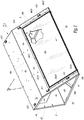
- the figure 1 represents a solar hybrid device 2, that is to say thermal and photovoltaic, which comprises a sheath 4 and a rectangular photovoltaic solar module 6.
- Sheath 4 is a right prism whose bases are open and are quadrilaterals.
- a base of the prism corresponds to an entry E of the sheath 4 and the other base corresponds to an output S of the sheath 4.
- a side surface of the sheath 4 has two lateral faces 4c and 4d which are perpendicular, a third lateral face 4b which forms an angle slightly smaller than 90 ° with the smaller face 4c among the two perpendicular faces 4c and 4d and a fourth face 4a which constitutes a front face of the sheath 4 and which has a rectangular opening opening at an edge of the sheath 4 formed by the faces 4a and 4d.
- the face 4d When the device 2 is in the installed configuration, the face 4d is horizontal and the face 4b is slightly inclined, which promotes the evacuation of rainwater, dead leaves, or any other undesirable body.
- the rectangular opening of the front face 4a is equipped with the photovoltaic module 6.
- the front face 4a has three portions in the form of rectangular strips which surround the rectangular opening: a portion 40a situated between the outlet S and the rectangular opening, a portion 40b located between the entrance E and the rectangular opening and a portion 40c located between the face 4b and the rectangular opening.
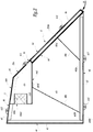
- an intermediate chamber 44 is located inside the sheath 4 at the edge formed by the faces 4a and 4b of the sheath 4.
- the intermediate chamber 44 has the geometry of a right prism whose faces 44a, 44b, 44c and 44d are respectively parallel to the faces 4a to 4d of the sheath 4 and whose faces 44a and 44b are respectively merged with the faces 4a and 4b of the sheath 4.
- the volume located inside the sheath 4 and outside the intermediate chamber 44 defines a main chamber 42.
- Two pairs of metal blades 48a and 48b improve the mechanical strength of the sheath 4 and constitute an internal structural reinforcement for the sheath 4.
- a first pair of blades 48a one of which is located near the inlet E of the sheath 4 and the other is located near the outlet S of the sheath 4, connects the faces 4a and 4d.
- the longitudinal axes of the blades of the first pair of blades 48a coincide with the figure 2 in a Z48a axis parallel to the bases of the sheath 4 and generally perpendicular to the front face 4a.
- the blades 48a have their ends 481a and 482a curved for their attachment to the faces 4a and 4d.
- First ends 481a of the blades 48a respectively extend against the portions 40a and 40b of the front face 4a.
- Second ends 482a of the blades 48a extend against the face 4d of the sheath 4.
- a second pair of blades 48b extends between the face 4d of the sheath 4 and the face 44d of the intermediate chamber 44.
- the blades 48b have their ends 481b and 482b bent to allow their attachment respectively to the face 44d and to the face 4d, similarly to the blades 48a.
- the longitudinal axes of the blades of the second pair of blades 48b are confused at the figure 2 in a Z48b axis parallel to the bases of the sheath 4 and generally coincides with the bisector of the faces 4a and 4b of the sheath 4.
- the faces 4a to 4d each comprise, at their edges located on the side of the inlet E and the outlet S, a portion bent at right angles to the inside of the sheath 4.
- the folded portions of the faces 4a to 4d on the side of the input E and on the output side S define a closed contour 45.
- the face 44c of the intermediate chamber 44 has three circular openings 444c, one of which is visible at the figure 2 , on which are connected supports 440 which have the geometry of a cylinder with circular base axis Z440 parallel to the face 44d.
- the supports 440 each enclose a flow regulator 5.
- the flow regulators 5 may be of the flap or diaphragm type.
- the flow regulators 5 are arranged between the intermediate chamber 44 and the main chamber 42. The flow regulators 5 do not create an air intake but vary the flow rate of the air flow that passes through them, this flow being put into operation. movement by auxiliary depressing means.
- the sheath 4 and the intermediate chamber 44 consist of folded metal sheets and assembled together by rivets not shown.
- the sheath 4 comprises assembly means in the form of ten semicircular fasteners each having a cylindrical hole of longitudinal axis parallel to the faces 4a to 4d.
- Two fastening elements 410 and 413 are assembled on the face 4b respectively close to the output S and the input E.
- Two fasteners 411 and 414 are assembled on the portion 40c of the face 4a, respectively close to the S output and input E.
- Two fasteners 412 and 415 are assembled respectively on the portions 40a and 40b of the face 4a.
- Two fastening elements 416 and 417 visible to the figure 2 are assembled on the face 4d close to the output S and two not shown fasteners are assembled on the face 4d near the entrance E.
- the fastening elements 416 and 417 are detrimental to the stability of the device 2 when it is installed on a flat horizontal surface but are useful when the device 2 is installed in a solar cap, that is to say overflow with respect to a device. vertical wall, in which case the fastening elements 416 and 417 are not in contact with a wall.
- the fasteners 416 and 417 are moved at the face 4c of the sheath.
- the figure 3 represents the photovoltaic module 6.
- the module 6 comprises a front face 62. When the module 6 is assembled with the sheath 4, the front face 62 is turned towards the outside of the sheath 4, as shown by the figures 1 and 2 .
- the front 62 is equipped with a solar panel 68 which is an electrical power generator consisting of a set of photovoltaic cells interconnected electrically.
- An insert 65 extends on a rear face 684 of the solar panel 68.
- the insert 65 has the geometry of a plate parallel to the solar panel 68.
- the section of the insert 65 taken along a plane perpendicular to the solar panel 68 , presents slots.
- Upper portions 652 of the slots, located on the front face 62 of the module 6, are assembled with the rear face 684 of the solar panel 68.
- Lower portions 654 of the slots, opposite to the front face 62 of the module 6, are assembled with a support 67 which is a plate parallel to the solar panel 68.
- the support 67 has its edges curved so as to grip the edges of a front face 682 of the solar panel 68.
- the slots of the insert 65 define channels 462 which together constitute a heat exchange chamber 46.
- the upper portions 652 and 654 of the slots are respectively assembled with the rear face 684 of the panel 68 and with the support 67, for example by means of silicone-based glue, which promotes heat exchange.
- a frame 66 is adapted to receive the solar panel 68, the insert 65 and the support 67.
- the frame 66 has the geometry of a rectangular plate whose three edges 66a, 66b and 66c comprise a flange 661.
- the flange 661 comprises a first portion 661a perpendicular to the solar panel 68 and a second portion 661b connected to the first portion 661a and parallel to the solar panel 68.
- the portion 661b of the flange 661 makes it possible to retain the solar panel 68, the insert 65 and the support 67 in the rectangular opening of the front face 4a.
- the portion 661b of the flange 661 is fixed to the face 4a by means not shown adapted to cooperate with holes 6610 formed on the portion 661b.
- the edge 66b of the frame 66 is located at the joint between the faces 44a and 44b of the intermediate chamber 44, so that the channels 462 defined by the insert 65 have their ends on the edge side 66b opening into the intermediate chamber 44 and having their ends on the edge side 66d opening out of the sheath 4.
- the end of the channels 462 located on the side of the edge 66d is equipped with a grid 69 shown in FIG. figure 3 which prevents impurities and animals from entering channels 462.
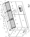
- the figure 5 represents an installation comprising a building 8, a heat pump 9 of the air / water type, three thermal and photovoltaic hybrid solar thermal devices 2a, 2b and 2c and vacuum means 10 controlled by a control unit 11.
- the devices 2a, 2b and 2c are located at the edge of a flat roof 82 of the building 8 and include means not shown for their attachment to the building 8. These fixing means may be composed of brackets fixed to the facade.
- the upstream and the downstream are defined relative to the direction of the flow of air in the installation, between the heat exchange chambers 46 and the depressurizing means 10.
- the air suction created by the depression means 10 is greater downstream than upstream.
- the output S of the device 2a is contiguous with the input E of the device 2b and the output S of the device 2b is contiguous with the input E of the device 2c.
- the contour 45 of the device 2a located at its output S is in contact with the contour 45 of the device 2b located on the side of its input E
- the contour 45 of the device 2b located at its output S is in contact with the contour 45 of the device 2c located at its entry E.
- the main chambers 42 of each device 2a, 2b and 2c form a single common chamber which is the union of the volumes of the main chambers 42 of each device 2a, 2b and 2c.
- the solar panels 68 of each device 2a, 2b and 2c are connected in series and are electrically connected to storage means 84, which may in practice be a battery, by an electric cable 840.
- the devices 2a, 2b and 2c are held together by unrepresented elements which cooperate with the fastening elements 410 to 417. These elements may be, for example, bolts arranged in the cylindrical holes of the fastening elements 410 to 417.
- the elements of FIG. Fastener 410 to 417, for each pair of adjacent bases belonging to two adjacent devices, are facing each other in pairs and have their cylindrical holes aligned.
- the inlet E of the device 2a is obstructed by a not shown plate and the outlet S of the device 2c is obstructed by a plate 471 which has a circular orifice 4711 connected to an evaporator 92 of the heat pump 9 via a duct 93.
- the evaporator comprises a heat exchange zone which receives the duct 93 at its inlet and the outlet of which is equipped with vacuum means 10, such as a fan or a pump.
- the sheath 93 comprises ramifications connected to the air vents of the building 8, not shown, via secondary ducts.
- the branches comprise valves capable of selectively blocking each secondary duct.
- the photovoltaic cells of the solar panels 68 of the devices 2a, 2b and 2c exposed to solar radiation, produce electric current which supplies electrical energy to the storage means 84.
- the air flowing in the channels 462 from their ends connected to the outside of the devices 2a, 2b and 2c to their ends opening into the common chamber, constitutes an air gap.
- the air gap has a thickness, measured perpendicular to the front face 62 of the module 6, between 10 mm and 20 mm, preferably of the order of 15 mm. This thickness promotes heat exchange.
- the vacuum means 10 make it possible to circulate the ambient outside air successively through the devices 2a, 2b and 2c, the sheath 93 and the evaporator 92, at a speed not exceeding 3 m / s, which limits the noise generated by the air flows.
- the depressurizing means 10 circulate the air successively through the heat exchange chamber 46, the intermediate chamber 44, the flow regulators 5 and the main chamber 42.
- each heat exchange chamber 46 absorbs heat at each module 6 and heats up, thereby cooling each module 6.
- the flow regulators 5 ensure, for the air flowing between each intermediate chamber 44 and the common chamber formed by the main chambers 42, a substantially constant flow. In this way, the cooling of each module 6 is generally homogeneous and the temperature of the air at the outlet of each intermediate chamber 44 is generally homogeneous.
- the flow of air sucked into the heat exchange chamber 46 of the device 2c would be important because the device 2c is located near vacuum means 10, the flow of air sucked into the heat exchange chamber 46 of the device 2b would be moderate because the device 2b is located downstream of the device 2a and the flow of air sucked into the device 2a would be weak because the device 2a is located downstream of the devices 2b and 2c.
- the flow regulators 5 make it possible to remedy the reduction in the efficiency of the suction of the upstream device 2a to the downstream device 2c, generated by the depressurizing means 10.
- the flow regulators 5 of each device 2a, 2b and 32c progressively reduce the air flow sucked through each device 2a, 2b and 2c, between the downstream device 2c and the upstream device 2a.
- the flow of air sucked through each device 2a, 2b, 2c is generally constant.
- the flow regulators 5 decrease more significantly the air flow sucked through the downstream device 2c than the flow of air sucked through the upstream device 2a.
- the flow regulators 5 regulate the passage of heated air in the channels 462 of the inserts 65 of each device 2a, 2b and 2c, to the main chamber 42 common devices 2. Then, the air travels through the conduit 93 and passes through the heat exchange zone of the evaporator 92 before being discharged into the outside atmosphere.
- the hot air that arrives in the evaporator 92 of the heat pump 9 makes it possible to produce domestic hot water, delivered by means of a pipe 94.
- the quantity of domestic hot water produced is sufficient to cover the needs of buildings for which the use of solar hot water is important, for example, hotels or retirement homes.
- the installation represented at figure 5 has three devices 2. However, in practice, the installation may comprise a number of devices greater than or equal to one.
- the sheath 4 and / or the intermediate chamber 44 may have the geometry of a prism polygonal base, for example triangular base.
- the intermediate chamber 44 may comprise the same number of supports 440 and flow regulators 5 different from three.
Description
La présente invention concerne un dispositif solaire hybride thermique et photovoltaïque ainsi qu'une installation comprenant un tel dispositif.The present invention relates to a solar hybrid thermal and photovoltaic device and an installation comprising such a device.
Dans le domaine du chauffage de l'air au moyen d'énergie solaire, il est connu de récupérer de la chaleur accumulée par des modules solaires hybrides, c'est-à-dire photovoltaïques et thermiques, au niveau de leurs faces arrières non exposées aux rayonnements solaires, en faisant circuler de l'air le long des faces arrières. Ainsi, l'air se réchauffe et peut être utilisé, par exemple, pour le chauffage de bâtiments.In the field of heating air by means of solar energy, it is known to recover the heat accumulated by hybrid solar modules, that is to say photovoltaic and thermal, at their unexposed rear faces. to solar radiation, by circulating air along the back faces. Thus, the air heats up and can be used, for example, for heating buildings.
Dans un dispositif solaire hybride thermique et photovoltaïque connu destiné à être installé sur une toiture plane d'un bâtiment, l'air ambiant extérieur est aspiré au travers d'un ensemble de tôles perforées, en amont desquelles se situe un ventilateur pour la circulation de l'air, et sur lesquelles sont disposés des modules solaires photovoltaïques. L'air circulant entre les modules solaires photovoltaïques et les tôles perforées récupère ainsi de la chaleur qui est valorisée pour le chauffage ou le préchauffage de l'air de ventilation d'un bâtiment.In a known solar hybrid thermal and photovoltaic device intended to be installed on a flat roof of a building, the outside ambient air is sucked through a set of perforated sheets, upstream of which is a fan for the circulation of air, and on which are arranged photovoltaic solar modules. The air flowing between the photovoltaic solar modules and the perforated sheets thus recovers heat that is valued for heating or preheating the ventilation air of a building.
Cependant, les débits d'air mis en oeuvre dans un tel système ne suffisent pas à chauffer suffisamment d'air pour des applications qui requièrent une puissance thermique supérieure à la puissance thermique nécessaire au chauffage ou au préchauffage de l'air de ventilation d'un bâtiment, telles que le chauffage de l'air en amont d'une pompe à chaleur utilisée pour la production de quantités importantes d'eau chaude sanitaire, ce qui n'est pas satisfaisant.However, the air flow rates implemented in such a system are not sufficient to heat enough air for applications that require a thermal power greater than the thermal power required to heat or preheat the ventilation air. a building, such as heating the air upstream of a heat pump used for the production of large quantities of domestic hot water, which is not satisfactory.
Par ailleurs, l'architecture et le poids d'un tel système ne permet pas une installation au voisinage de la façade d'un bâtiment, ce qui limite les possibilités d'orientation des modules solaires photovoltaïques et ne permet pas une valorisation optimale des rayonnements solaires. De plus, l'utilisation de ce système pour des applications nécessitant une grande puissance thermique requiert une surface de modules solaires photovoltaïques importante pour compenser la valorisation limitée des rayonnements solaires.Furthermore, the architecture and the weight of such a system does not allow installation in the vicinity of the facade of a building, which limits the possibilities of orientation of photovoltaic solar modules and does not allow optimal recovery of radiation solar. In addition, the use of this system for applications requiring high thermal power requires a large area of solar photovoltaic modules to compensate for the limited value of solar radiation.
C'est à ces inconvénients qu'entend plus particulièrement remédier l'invention en proposant un dispositif solaire hybride thermique et photovoltaïque et une installation comprenant un tel dispositif, qui permet de chauffer de l'air en amont d'une pompe à chaleur pour une utilisation qui requiert une grande puissance thermique. L'invention peut être utilisée notamment pour produire des quantités d'eau chaude sanitaire suffisantes pour des bâtiments pour lesquels les usages d'eau chaude sanitaire sont importants, par exemple des hôtels ou des maisons de retraite.It is these drawbacks that the invention intends to remedy more particularly by proposing a solar hybrid thermal and photovoltaic device and an installation comprising such a device, which makes it possible to heat air upstream of a heat pump for a use that requires a high thermal power. The invention can be used in particular to produce sufficient quantities of domestic hot water for buildings for which the use of hot water is important, for example hotels or retirement homes.
A cet effet, l'invention concerne un dispositif solaire hybride thermique et photovoltaïque comprenant au moins un module photovoltaïque équipé d'un panneau solaire connecté électriquement à un récepteur électrique, le module photovoltaïque comprenant une face avant orientée vers le soleil et une face arrière orientée à l'opposé du soleil et le dispositif comprenant
- au moins une chambre d'échange thermique s'étendant le long de la face arrière du module photovoltaïque,
- une chambre intermédiaire dans laquelle débouchent toutes les chambres d'échange thermique,
- une chambre principale apte à être reliée à une chambre principale d'un dispositif adjacent et/ou à des moyens de mise en dépression, et
- des moyens de régulation du débit d'air disposés entre la chambre intermédiaire et la chambre principale.
- at least one heat exchange chamber extending along the rear face of the photovoltaic module,
- an intermediate chamber into which all the heat exchange chambers open,
- a main chamber adapted to be connected to a main chamber of an adjacent device and / or to means of depression, and
- means for regulating the air flow rate arranged between the intermediate chamber and the main chamber.
Grâce à l'invention, lorsque plusieurs dispositifs solaires hybrides sont accolés de manière à ce que leurs chambres principales sont reliées entre elles et forment une seule chambre commune, le débit d'air passant de chaque chambre d'échange thermique à la chambre commune est sensiblement égal pour chaque dispositif solaire hybride, même si une source de dépression est placée à une extrémité de la chambre commune de sorte que chaque dispositif est soumis à une dépression d'intensité différente. De plus, l'intégration aux bâtiments des modules solaires photovoltaïques peut se faire en toiture terrasse, c'est-à-dire sur une toiture plane horizontale, ou en casquette solaire, c'est-à-dire en hauteur sur une façade d'un bâtiment. Par ailleurs, grâce à l'invention, il est possible de réchauffer des débits d'air importants pouvant servir à la production d'eau chaude sanitaire dans des bâtiments ayant des besoins importants en eau chaude sanitaire.Thanks to the invention, when several hybrid solar devices are contiguous so that their main chambers are interconnected and form a single common chamber, the flow of air passing from each heat exchange chamber to the common chamber is substantially equal for each hybrid solar device, even if a vacuum source is placed at one end of the common chamber so that each device is subjected to a depression of different intensity. Moreover, the integration of photovoltaic solar modules into buildings can be done on a flat roof, that is to say on a flat horizontal roof, or in a solar cap, that is to say in height on a facade of a building . Furthermore, thanks to the invention, it is possible to heat large air flows that can be used for the production of domestic hot water in buildings with significant domestic hot water needs.
Selon des aspects avantageux mais non obligatoires de l'invention, un tel dispositif peut incorporer une ou plusieurs des caractéristiques suivantes, prises dans toute combinaison techniquement admissible :
- La chambre d'échange thermique a une épaisseur, mesurée selon une direction perpendiculaire à la face avant du module photovoltaïque, comprise entre 10 mm et 20 mm, de préférence de l'ordre de 15 mm.
- La chambre d'échange thermique est délimitée par un insert qui est une plaque, globalement parallèle à la face avant du module photovoltaïque, ayant une section, prise perpendiculairement à la face avant, en forme de créneaux qui délimitent des canaux aptes à relier l'extérieur du dispositif à la chambre intermédiaire. Des segments supérieurs des créneaux sont en contact avec une face arrière du panneau solaire et des segments inférieurs des créneaux, globalement parallèles aux segments supérieurs, sont en contact avec une plaque qui délimite une partie arrière de la chambre d'échange thermique.
- La chambre principale a la géométrie d'un prisme à base polygonale et le module photovoltaïque équipe une face du prisme.
- La chambre principale et la chambre intermédiaire sont composées en partie d'un ensemble de tôles métalliques et sont fabriquées en partie par pliage et par rivetage de ces tôles métalliques.
- La chambre principale est équipée d'au moins un renfort structurel interne.
- Le dispositif comprend des moyens pour la fixation du dispositif en toiture ou en façade d'un bâtiment.
- Les moyens de régulation du débit d'air ne créent pas une aspiration d'air.
- The heat exchange chamber has a thickness, measured in a direction perpendicular to the front face of the photovoltaic module, of between 10 mm and 20 mm, preferably of the order of 15 mm.
- The heat exchange chamber is delimited by an insert which is a plate, generally parallel to the front face of the photovoltaic module, having a section, taken perpendicularly to the front face, in the form of crenellations which delimit channels capable of connecting the outside the device to the intermediate chamber. Upper segments of the slots are in contact with a rear face of the solar panel and lower segments of the slots, generally parallel to the upper segments, are in contact with a plate which delimits a rear portion of the heat exchange chamber.
- The main chamber has the geometry of a polygonal prism and the photovoltaic module equips one side of the prism.
- The main chamber and the intermediate chamber are composed in part of a set of metal sheets and are made partly by folding and riveting of these metal sheets.
- The master bedroom is equipped with at least one internal structural reinforcement.
- The device comprises means for fixing the device on the roof or facade of a building.
- The means for regulating the air flow do not create an air intake.
L'invention concerne également une installation comprenant une pompe à chaleur de type air/eau, au moins deux dispositifs solaires hybrides thermiques et photovoltaïques conformes à l'invention et des moyens de mise en dépression aptes à faire circuler de l'air depuis une entrée jusqu'à une sortie d'un circuit aéraulique ouvert comportant
- les dispositifs montés en série de sorte que leurs chambres principales respectives sont raccordées l'une à l'autre et forment une seule chambre commune, et
- une sortie d'air ménagée dans un dernier dispositif, le plus proche des moyens de mise en dépression, et reliée avec un évaporateur de la pompe à chaleur.
- the devices connected in series so that their respective main chambers are connected to one another and form a single common chamber, and
- an air outlet in a last device, the closest to the vacuum means, and connected with an evaporator of the heat pump.
Selon des caractéristiques avantageuses mais non obligatoires de l'invention, une telle installation peut également inclure les caractéristiques suivantes, prises dans toute combinaison techniquement admissible :
- Les moyens de mise en dépression sont aptes à faire circuler l'air dans le circuit aéraulique à une vitesse inférieure à 6 m/s.
- L'installation comprend une unité de commande pour la modulation du débit d'air du circuit aéraulique selon trois modes de fonctionnement qui dépendent notamment du paramétrage des moyens de mise en dépression :
- un mode dit grand débit adapté pour la production d'eau chaude sanitaire par la pompe à chaleur,
- un mode dit petit débit adapté pour refroidir les modules photovoltaïques, et
- un mode dit débit moyen adapté pour le renouvellement de l'air intérieur d'un bâtiment et le refroidissement des modules photovoltaïques.
- Les moyens de régulation du débit d'air diminuent progressivement le débit d'air aspiré au travers de chaque dispositif, entre le dispositif aval et le dispositif amont, de sorte que le débit d'air aspiré au travers de chaque dispositif est globalement constant.
- The vacuum means are able to circulate the air in the air flow at a speed below 6 m / s.
- The installation comprises a control unit for the modulation of the air flow of the air-flow circuit according to three modes of operation which depend in particular on the parameterization of the means of depression:
- a mode known as high flow rate adapted for the production of domestic hot water by the heat pump,
- a so-called small flow mode adapted to cool the photovoltaic modules, and
- a so-called medium flow mode adapted for the renewal of the interior air of a building and the cooling of the photovoltaic modules.
- The means of regulating the air flow rate progressively reduce the air flow sucked through each device, between the downstream device and the upstream device, so that the air flow sucked through each device is generally constant.
L'invention sera mieux comprise et d'autres avantages de celle-ci apparaîtront plus clairement à la lumière de la description qui va suivre d'un dispositif solaire hybride et photovoltaïque et d'une installation comprenant un dispositif conforme à son principe, donnée uniquement à titre d'exemple et faite en référence aux dessins annexés dans lesquels :
- la
figure 1 est une vue en perspective d'un dispositif solaire hybride thermique et photovoltaïque conforme à l'invention ; - la
figure 2 est une coupe selon le plan II à lafigure 1 ; - la
figure 3 est une vue en perspective d'un module photovoltaïque appartenant au dispositif de lafigure 1 ; - la
figure 4 est une coupe selon la ligne IV-IV à lafigure 3 ; et - la
figure 5 est un schéma d'une installation comprenant plusieurs dispositifs conformes à l'invention.
- the
figure 1 is a perspective view of a solar hybrid thermal and photovoltaic device according to the invention; - the
figure 2 is a cut according to plan II to thefigure 1 ; - the
figure 3 is a perspective view of a photovoltaic module belonging to the device of thefigure 1 ; - the
figure 4 is a section along the line IV-IV to thefigure 3 ; and - the
figure 5 is a diagram of an installation comprising several devices according to the invention.
La
La gaine 4 est un prisme droit dont les bases sont ouvertes et sont des quadrilatères. Une base du prisme correspond à une entrée E de la gaine 4 et l'autre base correspond à une sortie S de la gaine 4. Une surface latérale de la gaine 4 comporte deux faces latérales 4c et 4d qui sont perpendiculaires, une troisième face latérale 4b qui forme un angle légèrement inférieur à 90° avec la face de plus petites dimensions 4c parmi les deux faces perpendiculaires 4c et 4d et une quatrième face 4a qui constitue une face avant de la gaine 4 et qui comporte une ouverture rectangulaire débouchant au niveau d'une arête de la gaine 4 formée par les faces 4a et 4d. Lorsque le dispositif 2 est en configuration installée, la face 4d est horizontale et la face 4b est légèrement inclinée, ce qui permet de favoriser l'évacuation de l'eau de pluie, des feuilles mortes, ou de tout autre corps indésirable. Comme le montrent les
Comme le montre plus particulièrement la
Le volume situé à l'intérieur de la gaine 4 et à l'extérieur de la chambre intermédiaire 44 définit une chambre principale 42.The volume located inside the
Deux paires de lames métalliques 48a et 48b améliorent la résistance mécanique de la gaine 4 et constituent un renfort structurel interne pour la gaine 4. Une première paire de lames 48a, dont l'une est située à proximité de l'entrée E de la gaine 4 et l'autre est située à proximité de la sortie S de la gaine 4, relie les faces 4a et 4d. Les axes longitudinaux des lames de la première paire de lames 48a sont confondus à la
Une deuxième paire de lames 48b s'étend entre la face 4d de la gaine 4 et la face 44d de la chambre intermédiaire 44. Les lames 48b ont leurs extrémités 481b et 482b recourbées pour permettre leur fixation respectivement à la face 44d et à la face 4d, de manière analogue aux lames 48a. Les axes longitudinaux des lames de la de la deuxième paire de lames 48b sont confondus à la
Les faces 4a à 4d comportent chacune, au niveau de leurs arêtes situées du côté de l'entrée E et de la sortie S, une portion pliée à angle droit vers l'intérieur de la gaine 4. Les portions pliées des faces 4a à 4d du côté de l'entrée E et du côté de la sortie S définissent un contour 45 fermé.The faces 4a to 4d each comprise, at their edges located on the side of the inlet E and the outlet S, a portion bent at right angles to the inside of the
La face 44c de la chambre intermédiaire 44 comporte trois ouvertures circulaires 444c, dont l'une est visible à la
La gaine 4 et la chambre intermédiaire 44 sont constituées de tôles métalliques pliées et assemblées entre elles par des rivets non représentés.The
La gaine 4 comporte des moyens d'assemblage sous la forme de dix éléments de fixation semi-circulaires présentant chacun un trou cylindrique d'axe longitudinal parallèle aux faces 4a à 4d.The
Deux éléments de fixation 410 et 413 sont assemblés sur la face 4b respectivement à proximité de la sortie S et de l'entrée E. Deux éléments de fixation 411 et 414 sont assemblés sur la portion 40c de la face 4a, respectivement à proximité de la sortie S et de l'entrée E. Deux éléments de fixation 412 et 415 sont assemblés respectivement sur les portions 40a et 40b de la face 4a. Deux éléments de fixation 416 et 417 visibles à la
Les éléments de fixation 416 et 417 nuisent à la stabilité du dispositif 2 lorsqu'il est installé sur une surface plane horizontale mais sont utiles lorsque le dispositif 2 est installé en casquette solaire, c'est-à-dire en débordement par rapport à une paroi verticale, auquel cas les éléments de fixation 416 et 417 ne sont pas en contact avec une paroi. Lorsque le dispositif 2 doit être installé sur une surface plane horizontale, les éléments de fixation 416 et 417 sont déplacés au niveau de la face 4c de la gaine.The
La
Un insert 65 s'étend sur une face arrière 684 du panneau solaire 68. L'insert 65 a la géométrie d'une plaque parallèle au panneau solaire 68. La section de l'insert 65, prise selon un plan perpendiculaire au panneau solaire 68, présente des créneaux. Des portions supérieures 652 des créneaux, situées du côté de la face avant 62 du module 6, sont assemblées avec la face arrière 684 du panneau solaire 68. Des portions inférieures 654 des créneaux, opposés à la face avant 62 du module 6, sont assemblées avec un support 67 qui est une plaque parallèle au panneau solaire 68. Le support 67 a ses bords recourbés de manière à enserrer les bords d'une face avant 682 du panneau solaire 68.An insert 65 extends on a
Les créneaux de l'insert 65 définissent des canaux 462 qui constituent ensemble une chambre d'échange thermique 46.The slots of the insert 65 define
Les portions supérieures 652 et inférieures 654 des créneaux sont assemblées respectivement avec la face arrière 684 du panneau 68 et avec le support 67, par exemple au moyen de colle à base de silicone, ce qui favorise les échanges thermiques.The
Un bâti 66 est adapté pour recevoir le panneau solaire 68, l'insert 65 et le support 67. Le bâti 66 a la géométrie d'une plaque rectangulaire dont trois bords 66a, 66b et 66c comportent un rebord 661. Le rebord 661 comprend une première portion 661a perpendiculaire au panneau solaire 68 et une deuxième portion 661b reliée à la première portion 661a et parallèle au panneau solaire 68. La portion 661b du rebord 661 permet de retenir le panneau solaire 68, l'insert 65 et le support 67 dans l'ouverture rectangulaire de la face avant 4a. La portion 661b du rebord 661 est fixée à la face 4a par des moyens non représentés aptes à coopérer avec des trous 6610 ménagés sur la portion 661b.A
Lorsque le module photovoltaïque 6 est assemblé avec la gaine 4, le bord 66b du bâti 66 est situé au niveau de la jointure entre les faces 44a et 44b de la chambre intermédiaire 44, de sorte que les canaux 462 définis par l'insert 65 ont leurs extrémités situées du côté du bord 66b qui débouchent dans la chambre intermédiaire 44 et ont leurs extrémités situées du côté du bord 66d qui débouchent à l'extérieur de la gaine 4.When the
L'extrémité des canaux 462 située du côté du bord 66d est équipée d'une grille 69 représentée à la
La
Les dispositifs 2a, 2b et 2c sont situés en bordure d'une toiture 82 plane du bâtiment 8 et comportent des moyens non représentés pour leur fixation au bâtiment 8. Ces moyens de fixation peuvent être composés d'équerres fixées sur la façade.The
On définit l'amont et l'aval relativement au sens de l'écoulement d'air dans l'installation, entre les chambres d'échange thermique 46 et les moyens de mise en dépression 10. L'aspiration d'air créée par les moyens de mise en dépression 10 est plus importante à l'aval qu'à l'amont.The upstream and the downstream are defined relative to the direction of the flow of air in the installation, between the
La sortie S du dispositif 2a est accolée avec l'entrée E du dispositif 2b et la sortie S du dispositif 2b est accolée avec l'entrée E du dispositif 2c. Ainsi, le contour 45 du dispositif 2a situé au niveau de sa sortie S est en contact avec le contour 45 du dispositif 2b situé du côté de son entrée E, et le contour 45 du dispositif 2b situé au niveau de sa sortie S est en contact avec le contour 45 du dispositif 2c situé au niveau de son entrée E.The output S of the
Les chambres principales 42 de chaque dispositif 2a, 2b et 2c forment une seule chambre commune qui est la réunion des volumes des chambres principales 42 de chaque dispositif 2a, 2b et 2c. Les panneaux solaires 68 de chaque dispositif 2a, 2b et 2c sont branchés en série et sont reliés électriquement à des moyens de stockage 84, pouvant être en pratique une batterie, par un câble électrique 840.The
Les dispositifs 2a, 2b et 2c sont maintenus ensemble par des éléments non représentés qui coopèrent avec les éléments de fixation 410 à 417. Ces éléments peuvent être par exemple des boulons disposés dans les trous cylindriques des éléments de fixation 410 à 417. Les éléments de fixation 410 à 417, pour chaque paire de bases adjacentes appartenant à deux dispositifs adjacents, sont en regard deux à deux et ont leurs trous cylindriques alignés.The
L'entrée E du dispositif 2a est obstruée par une plaque non représentée et la sortie S du dispositif 2c est obstruée par une plaque 471 qui comporte un orifice circulaire 4711 relié à un évaporateur 92 de la pompe à chaleur 9 par un conduit 93.The inlet E of the
L'évaporateur comporte une zone d'échange thermique qui reçoit en entrée le conduit 93 et dont la sortie est équipée de moyens de mise en dépression 10, tels qu'un ventilateur ou une pompe.The evaporator comprises a heat exchange zone which receives the
La gaine 93 comprend des ramifications reliées à des bouches d'aération du bâtiment 8 non représentées, par l'intermédiaire de conduits secondaires. Les ramifications comportent des clapets aptes à obstruer sélectivement chaque conduit secondaire.The
En fonctionnement, les cellules photovoltaïques des panneaux solaires 68 des dispositifs 2a, 2b et 2c, exposées aux rayonnements solaires, produisent du courant électrique qui alimente en énergie électrique les moyens de stockage 84.In operation, the photovoltaic cells of the
Par ailleurs, le soleil réchauffe les modules 6 de chaque dispositif 2a, 2b et 2c et des échanges thermiques ont lieu entre les panneaux solaires 68, les inserts 65, les bâtis 66 et les supports 67. L'air qui circule dans les canaux 462, depuis leurs extrémités reliées à l'extérieur des dispositifs 2a, 2b et 2c jusqu'à leurs extrémités débouchant dans la chambre commune, constitue une lame d'air. La lame d'air a une épaisseur, mesurée perpendiculairement à la face avant 62 du module 6, comprise entre 10 mm et 20 mm, de préférence de l'ordre de 15 mm. Cette épaisseur favorise les échanges thermiques.Moreover, the sun warms the
Les moyens de mise en dépression 10 permettent de faire circuler l'air extérieur ambiant successivement à travers les dispositifs 2a, 2b et 2c, la gaine 93 et l'évaporateur 92, à une vitesse n'excédant pas 3 m/s, ce qui limite le bruit généré par les flux d'air. Pour chaque dispositif 2a, 2b et 2c, les moyens de mise en dépression 10 font circuler l'air successivement à travers la chambre d'échange thermique 46, la chambre intermédiaire 44, les régulateurs de débit 5 et la chambre principale 42.The vacuum means 10 make it possible to circulate the ambient outside air successively through the
Après avoir atteint l'évaporateur 92, l'air est expulsé vers l'extérieur. La circulation de l'air, à partir de l'entrée E du dispositif 2a jusqu'à l'évaporateur 92, provoque une aspiration de l'air extérieur dans les créneaux 462 des inserts 65 de chaque dispositif 2a, 2b et 2c. Cette aspiration est représentée par la flèche F1 à la
L'air qui circule dans chaque chambre d'échange thermique 46 absorbe de la chaleur à chaque module 6 et se réchauffe, refroidissant ainsi chaque module 6. Les régulateurs de débit 5 assurent, pour l'air circulant entre chaque chambre intermédiaire 44 et la chambre commune formée par les chambres principales 42, un débit sensiblement constant. De cette manière, le refroidissement de chaque module 6 est globalement homogène et la température de l'air en sortie de chaque chambre intermédiaire 44 est globalement homogène.The air circulating in each
En effet, si les dispositifs 2a, 2b et 2c n'étaient pas équipés de régulateurs de débit 5, le débit de l'air aspiré dans la chambre d'échange thermique 46 du dispositif 2c serait important car le dispositif 2c est situé à proximité des moyens de mise en dépression 10, le débit de l'air aspiré dans la chambre d'échangé thermique 46 du dispositif 2b serait modéré car le dispositif 2b est situé en aval du dispositif 2a et le débit de l'air aspiré dans le dispositif 2a serait faible car le dispositif 2a est situé en aval des dispositifs 2b et 2c. En d'autres termes, les régulateurs de débit 5 permettent de remédier à la diminution de l'efficacité de l'aspiration du dispositif amont 2a au dispositif aval 2c, générée par les moyens de mise en dépression 10.Indeed, if the
Les régulateurs de débit 5 de chaque dispositif 2a, 2b et 32c diminuent progressivement le débit d'air aspiré au travers de chaque dispositif 2a, 2b et 2c, entre le dispositif aval 2c et le dispositif amont 2a. Ainsi, le débit d'air aspiré au travers de chaque dispositif 2a, 2b, 2c est globalement constant. En d'autres termes, les régulateurs de débit 5 diminuent de manière plus prononcée le débit d'air aspiré au travers du dispositif aval 2c que le débit d'air aspiré au travers du dispositif amont 2a.The
De manière connue, le rendement des panneaux solaires chute lorsque leur température s'élève. Pour une installation comportant plusieurs panneaux solaires montés en série, le panneau solaire de plus faible rendement diminue le rendement de toute l'installation. Les régulateurs de débit 5 permettent de remédier à ces inconvénients.In known manner, the efficiency of the solar panels drops when their temperature rises. For an installation with multiple solar panels in series, the lower solar panel reduces the efficiency of the entire installation. The
Les régulateurs de débit 5 régulent le passage de l'air chauffé dans les canaux 462 des inserts 65 de chaque dispositif 2a, 2b et 2c, jusqu'à la chambre principale 42 commune des dispositifs 2. Puis, l'air parcourt le conduit 93 et traverse la zone d'échanges thermique de l'évaporateur 92 avant d'être rejeté dans l'atmosphère extérieure. L'air chaud qui arrive dans l'évaporateur 92 de la pompe à chaleur 9 permet de produire de l'eau chaude sanitaire, délivrée au moyen d'un tuyau 94.The
La quantité d'eau chaude sanitaire produite est suffisante pour couvrir les besoins de bâtiments pour lesquels les usages d'eau chaude solaire sont importants, par exemple, des hôtels ou les maisons de retraite.The quantity of domestic hot water produced is sufficient to cover the needs of buildings for which the use of solar hot water is important, for example, hotels or retirement homes.
L'unité de commande 11 pilote la vitesse des moyens de mise en dépression 10 au moyen d'un signal S10 acheminé de l'unité de commande 11 jusqu'aux moyens de mise en dépression 10 par un câble électrique 111. L'unité de commande 11 permet de piloter les moyens de mise en dépression 10 selon trois vitesses correspondant à trois modes de fonctionnement de l'installation :
- Un premier mode de fonctionnement dit grand débit, correspondant à une dépression élevée, optimise la production d'eau chaude sanitaire, lorsque la production d'eau chaude sanitaire est en cours. Eventuellement, l'unité de commande 11 peut piloter les clapets pour permettre un chauffage de l'air ambiant du bâtiment 8.
- Un mode de fonctionnement dit petit débit, correspondant à une vitesse faible de ventilation, assure le seul refroidissement des
modules 6. Dans ce cas, l'unité de commande 11 pilote les clapets pour bloquer le passage de l'air dans les conduits secondaires. - Un mode de fonctionnement dit débit moyen, correspondant à une vitesse de ventilation moyenne, assure un réchauffage de l'air de renouvellement du bâtiment 8 par les bouches d'aération et le refroidissement des
modules 6. Dans ce cas, l'unité de commande 11 pilote les clapets pour autoriser le passage de l'air dans les conduits secondaires.
- A first mode of operation said large flow, corresponding to a high vacuum, optimizes the production of domestic hot water, when the production of domestic hot water is in progress. Optionally, the
control unit 11 can control the flaps to allow heating of the ambient air of thebuilding 8. - A so-called small flow mode of operation, corresponding to a low ventilation speed, ensures the only cooling of the
modules 6. In this case, thecontrol unit 11 controls the valves to block the passage of air in the secondary ducts. - An operating mode, said average flow rate, corresponding to an average ventilation speed, ensures heating of the renewal air of the
building 8 through the air vents and the cooling of themodules 6. In this case, thecontrol unit 11 pilot the valves to allow the passage of air in the secondary ducts.
L'installation représentée à la
Dans un autre mode de réalisation de l'invention, non représenté, la gaine 4 et/ou la chambre intermédiaire 44 peuvent avoir la géométrie d'un prisme à base polygonale, par exemple à base triangulaire.In another embodiment of the invention, not shown, the
Dans un autre mode de réalisation de l'invention, non représenté, la chambre intermédiaire 44 peut comporter un même nombre de supports 440 et de régulateurs de débit 5 différent de trois.In another embodiment of the invention, not shown, the
Claims (12)
- Hybrid photovoltaic thermal solar device (2) comprising at least one photovoltaic module (6) equipped with a solar panel (68) electrically connected to an electrical receiver (84), the photovoltaic module comprising a front face (62) oriented towards the sun and a rear face (64) oriented away from the sun, characterised in that it comprises- at least one thermal exchange chamber (46) extending along the rear face (64) of the photovoltaic module (6),- an intermediate chamber (44) into which all the thermal exchange chambers (46) open,- a main chamber (42) capable of being connected to a main chamber (42) of an adjacent device (2) and/or to depressurisation means (10), and- means (5) for regulating the air flow arranged between the intermediate chamber (44) and the main chamber (42).
- Hybrid photovoltaic thermal solar device (2) according to claim 1, characterised in that the thermal exchange chamber (46) has a thickness, measured in a direction perpendicular to the front face (62) of the photovoltaic module (6), of between 10 mm and 20 mm, preferably of approximately 15 mm.
- Hybrid photovoltaic thermal solar device (2) according to any one of the preceding claims, characterised
in that the thermal exchange chamber (46) is delimited by an insert (65) which is a plate, generally parallel to the front face (62) of the photovoltaic module (6), having a cross-section, taken perpendicularly to the front face (62), in the form of crenellations which delimit channels (462) capable of connecting the exterior of the device (2) to the intermediate chamber (44),- in that upper segments (652) of the crenellations are in contact with a rear face (684) of the solar panel (68),and in that lower segments (654) of the crenellations, which are generally parallel to the upper segments (652), are in contact with a plate (67) which delimits a rear portion of the thermal exchange chamber (46). - Hybrid photovoltaic thermal solar device (2) according to any one of the preceding claims, characterised
in that the main chamber (42) has the geometry of a polygon-base prism,
and in that the photovoltaic module (6) is provided on a face (4a) of the prism. - Hybrid photovoltaic thermal solar device (2) according to any one of the preceding claims, characterised in that the main chamber (42) and the intermediate chamber (44) are composed in part of a set of metal sheets and are fabricated in part by bending and by riveting of the metal sheets.
- Hybrid photovoltaic thermal solar device (2) according to any one of the preceding claims, characterised in that the main chamber (42) is equipped with at least one internal structural reinforcement (48a, 48b).
- Hybrid photovoltaic thermal solar device (2) according to any one of the preceding claims, characterised in that it comprises means for fixing the device (2) to the roof (52) or to the façade of a building (8).
- Hybrid photovoltaic thermal solar device (2) according to any one of the preceding claims, characterised in that the means (5) for regulating the air flow do not create an intake of air.
- Arrangement comprising a heat pump (9) of the air/water type and at least two hybrid photovoltaic thermal solar devices (2a, 2b, 2c) according to any one of the preceding claims, characterised in that depressurisation means (10) are capable of circulating air from upstream to downstream, from an inlet to an outlet of an open aeraulic circuit comprising- the devices (2a, 2b, 2c) mounted in series from upstream to downstream, so that their respective main chambers (42) are connected to one another and form a single common chamber, and- an air outlet formed in a downstream device (2c), closest to the depressurisation means, and connected to an evaporator (92) of the heat pump (9).
- Arrangement according to claim 9, characterised in that the depressurisation means (10) are capable of circulating the air in the aeraulic circuit at a speed of less than 6 m/s.
- Arrangement according to either claim 9 or claim 10, characterised in that it comprises a control unit (11) for modulating the air flow of the aeraulic circuit according to three operating modes which depend especially on the configuration of the depressurisation means (10):- a mode called the high-flow mode, adapted to produce hot water for sanitary purposes by means of the heat pump (9),- a mode called the low-flow mode, adapted to cool the photovoltaic modules (6), and- a mode called the medium-flow mode, adapted to renew the air inside a building (8) and to cool the photovoltaic modules (6).
- Arrangement according to any one of claims 9 to 11, characterised in that the means (5) for regulating the air flow progressively reduce the air flow taken in through each device (2a, 2b, 2c), between the downstream device (2c) and the upstream device (2a), so that the air flow taken in through each device (2a, 2b, 2c) is generally constant.
Applications Claiming Priority (1)
| Application Number | Priority Date | Filing Date | Title |
|---|---|---|---|
| FR1056061A FR2963164B1 (en) | 2010-07-23 | 2010-07-23 | THERMAL AND PHOTOVOLTAIC HYBRID SOLAR DEVICE AND INSTALLATION COMPRISING SUCH A DEVICE |
Publications (3)
| Publication Number | Publication Date |
|---|---|
| EP2410578A2 EP2410578A2 (en) | 2012-01-25 |
| EP2410578A3 EP2410578A3 (en) | 2013-10-09 |
| EP2410578B1 true EP2410578B1 (en) | 2018-10-17 |
Family
ID=43919946
Family Applications (1)
| Application Number | Title | Priority Date | Filing Date |
|---|---|---|---|
| EP11174898.4A Not-in-force EP2410578B1 (en) | 2010-07-23 | 2011-07-21 | Thermal-photovoltaic hybrid solar device and installation including such a device |
Country Status (2)
| Country | Link |
|---|---|
| EP (1) | EP2410578B1 (en) |
| FR (1) | FR2963164B1 (en) |
Cited By (1)
| Publication number | Priority date | Publication date | Assignee | Title |
|---|---|---|---|---|
| CN110557090A (en) * | 2019-09-29 | 2019-12-10 | 北京普阳高科科技有限公司 | Solar energy device |
Families Citing this family (3)
| Publication number | Priority date | Publication date | Assignee | Title |
|---|---|---|---|---|
| WO2018138238A1 (en) * | 2017-01-26 | 2018-08-02 | Kea Holding I Aps | A photovoltaic panel mounting structure |
| ES2692727B2 (en) * | 2017-06-01 | 2020-03-17 | Longuetto Antonino Adriano Trimboli | SOLAR SELF-SUPPLY MODULE |
| CN110518877A (en) * | 2019-09-29 | 2019-11-29 | 北京普阳高科科技有限公司 | Solar thermoelectric coproduction device |
Family Cites Families (4)
| Publication number | Priority date | Publication date | Assignee | Title |
|---|---|---|---|---|
| DE2850844A1 (en) * | 1978-11-24 | 1980-06-04 | Bauer Geb Koerzdoerfer Ingebor | ROOF TILES AND RELATED ARRANGEMENT FOR A ROOF COVER |
| DE19914079A1 (en) * | 1999-03-27 | 2000-09-28 | Abac Elektronische Kommunikati | Photovoltaic module mount to wall of building has at least one heat exchanger located on the facade wall while air may flow between module and wall via channel |
| US6372978B1 (en) * | 2000-12-21 | 2002-04-16 | Carmine Cifaldi | Wind/sun solar collection system (HS2) |
| DE102008054099A1 (en) * | 2008-10-31 | 2010-05-20 | Reichert, Heiko, Dipl.-Ing. | Arrangement and procedure for the use of heat generation on photovoltaic systems within building services |
-
2010
- 2010-07-23 FR FR1056061A patent/FR2963164B1/en not_active Expired - Fee Related
-
2011
- 2011-07-21 EP EP11174898.4A patent/EP2410578B1/en not_active Not-in-force
Non-Patent Citations (1)
| Title |
|---|
| None * |
Cited By (1)
| Publication number | Priority date | Publication date | Assignee | Title |
|---|---|---|---|---|
| CN110557090A (en) * | 2019-09-29 | 2019-12-10 | 北京普阳高科科技有限公司 | Solar energy device |
Also Published As
| Publication number | Publication date |
|---|---|
| FR2963164A1 (en) | 2012-01-27 |
| EP2410578A2 (en) | 2012-01-25 |
| EP2410578A3 (en) | 2013-10-09 |
| FR2963164B1 (en) | 2012-09-07 |
Similar Documents
| Publication | Publication Date | Title |
|---|---|---|
| EP2410578B1 (en) | Thermal-photovoltaic hybrid solar device and installation including such a device | |
| FR2876223A1 (en) | DEVICE FOR COOLING BATTERIES OF A MOTORIZED ELECTRIC AND / OR HYBRID VEHICLE | |
| FR2924864A1 (en) | Photovoltaic solar module for electric energy producing device to warm-up house i.e. summer/winter ventilated house, has cooling unit with convection unit that is arranged to increase flow of air from heat exchanger at interior of channel | |
| CA2757318A1 (en) | Reversible radiator | |
| WO2020058608A1 (en) | Ventilating device for a motor vehicle | |
| EP2623909B1 (en) | Photovoltaic panel with heat recovery | |
| FR2509023A1 (en) | Greenhouse effect solar panel for air conditioning - has black body formed of internal chicane elements containing air conduits and photovoltaic cells on upper part of solar panel | |
| EP2236353A1 (en) | Ventilated panel and vehicle equipped with such a panel | |
| WO2019186076A1 (en) | Ventilation device for a motor vehicle | |
| WO2020002807A1 (en) | Ventilation device for a motor vehicle | |
| FR3083592A1 (en) | DEVICE FOR RECOVERING ENERGY BETWEEN GASEOUS FLUIDS, AND METHOD FOR MANUFACTURING SUCH A DEVICE | |
| EP3379157B1 (en) | Hot air and ventilation distribution valve for a façade with heat recovery | |
| EP2405209A1 (en) | Air-intake and mixing device for a heat pump | |
| FR3085891A1 (en) | HEAT EXCHANGE MODULE FOR MOTOR VEHICLE | |
| EP2529415A2 (en) | Module for mixed photovoltaic and thermal power generation from solar radiation, and plant provided with such modules | |
| WO2020058609A1 (en) | Heat exchanger module for a motor vehicle | |
| FR3070320B1 (en) | COOLING UNIT FOR A MOTOR VEHICLE | |
| FR3085885A1 (en) | VENTILATION DEVICE FOR A MOTOR VEHICLE | |
| WO2011067490A1 (en) | Motor vehicle comprising an electrical engine supplied with power by means of a battery, and means for cooling said battery | |
| CA3192478A1 (en) | Solar heating system | |
| EP3732379A1 (en) | Ventilation device for a motor vehicle | |
| FR3077239A1 (en) | VENTILATION DEVICE FOR A HEAT EXCHANGE MODULE OF A MOTOR VEHICLE | |
| FR2973576A1 (en) | Photovoltaic panel for roof of house to produce electricity, has air flow modifying elements arranged inside air conduit to modify air flow in conduit, and wall made of low thermal conductive material and delimiting lower side of conduit | |
| FR3082880A1 (en) | VENTILATION DEVICE FOR A MOTOR VEHICLE | |
| FR3069618A1 (en) | VENTILATION DEVICE FOR MOTOR VEHICLE |
Legal Events
| Date | Code | Title | Description |
|---|---|---|---|
| AK | Designated contracting states |
Kind code of ref document: A2 Designated state(s): AL AT BE BG CH CY CZ DE DK EE ES FI FR GB GR HR HU IE IS IT LI LT LU LV MC MK MT NL NO PL PT RO RS SE SI SK SM TR |
|
| AX | Request for extension of the european patent |
Extension state: BA ME |
|
| PUAI | Public reference made under article 153(3) epc to a published international application that has entered the european phase |
Free format text: ORIGINAL CODE: 0009012 |
|
| PUAL | Search report despatched |
Free format text: ORIGINAL CODE: 0009013 |
|
| AK | Designated contracting states |
Kind code of ref document: A3 Designated state(s): AL AT BE BG CH CY CZ DE DK EE ES FI FR GB GR HR HU IE IS IT LI LT LU LV MC MK MT NL NO PL PT RO RS SE SI SK SM TR |
|
| AX | Request for extension of the european patent |
Extension state: BA ME |
|
| RIC1 | Information provided on ipc code assigned before grant |
Ipc: H01L 31/058 20060101AFI20130904BHEP |
|
| 17P | Request for examination filed |
Effective date: 20131112 |
|
| RBV | Designated contracting states (corrected) |
Designated state(s): AL AT BE BG CH CY CZ DE DK EE ES FI FR GB GR HR HU IE IS IT LI LT LU LV MC MK MT NL NO PL PT RO RS SE SI SK SM TR |
|
| RAP1 | Party data changed (applicant data changed or rights of an application transferred) |
Owner name: CARRIER CORPORATION |
|
| REG | Reference to a national code |
Ref country code: DE Ref legal event code: R079 Ref document number: 602011052916 Country of ref document: DE Free format text: PREVIOUS MAIN CLASS: H01L0031058000 Ipc: H02S0040440000 |
|
| GRAP | Despatch of communication of intention to grant a patent |
Free format text: ORIGINAL CODE: EPIDOSNIGR1 |
|
| RIC1 | Information provided on ipc code assigned before grant |
Ipc: H02S 40/44 20140101AFI20180410BHEP |
|
| STAA | Information on the status of an ep patent application or granted ep patent |
Free format text: STATUS: GRANT OF PATENT IS INTENDED |
|
| INTG | Intention to grant announced |
Effective date: 20180517 |
|
| RAP1 | Party data changed (applicant data changed or rights of an application transferred) |
Owner name: CARRIER CORPORATION |
|
| GRAS | Grant fee paid |
Free format text: ORIGINAL CODE: EPIDOSNIGR3 |
|
| GRAA | (expected) grant |
Free format text: ORIGINAL CODE: 0009210 |
|
| STAA | Information on the status of an ep patent application or granted ep patent |
Free format text: STATUS: THE PATENT HAS BEEN GRANTED |
|
| AK | Designated contracting states |
Kind code of ref document: B1 Designated state(s): AL AT BE BG CH CY CZ DE DK EE ES FI FR GB GR HR HU IE IS IT LI LT LU LV MC MK MT NL NO PL PT RO RS SE SI SK SM TR |
|
| REG | Reference to a national code |
Ref country code: GB Ref legal event code: FG4D Free format text: NOT ENGLISH |
|
| REG | Reference to a national code |
Ref country code: CH Ref legal event code: EP Ref country code: CH Ref legal event code: NV Representative=s name: MICHELI AND CIE SA, CH |
|
| REG | Reference to a national code |
Ref country code: IE Ref legal event code: FG4D Free format text: LANGUAGE OF EP DOCUMENT: FRENCH |
|
| REG | Reference to a national code |
Ref country code: DE Ref legal event code: R096 Ref document number: 602011052916 Country of ref document: DE Ref country code: AT Ref legal event code: REF Ref document number: 1055172 Country of ref document: AT Kind code of ref document: T Effective date: 20181115 |
|
| REG | Reference to a national code |
Ref country code: NL Ref legal event code: FP |
|
| REG | Reference to a national code |
Ref country code: SE Ref legal event code: TRGR |
|
| REG | Reference to a national code |
Ref country code: LT Ref legal event code: MG4D |
|
| REG | Reference to a national code |
Ref country code: AT Ref legal event code: MK05 Ref document number: 1055172 Country of ref document: AT Kind code of ref document: T Effective date: 20181017 |
|
| PG25 | Lapsed in a contracting state [announced via postgrant information from national office to epo] |
Ref country code: ES Free format text: LAPSE BECAUSE OF FAILURE TO SUBMIT A TRANSLATION OF THE DESCRIPTION OR TO PAY THE FEE WITHIN THE PRESCRIBED TIME-LIMIT Effective date: 20181017 Ref country code: HR Free format text: LAPSE BECAUSE OF FAILURE TO SUBMIT A TRANSLATION OF THE DESCRIPTION OR TO PAY THE FEE WITHIN THE PRESCRIBED TIME-LIMIT Effective date: 20181017 Ref country code: PL Free format text: LAPSE BECAUSE OF FAILURE TO SUBMIT A TRANSLATION OF THE DESCRIPTION OR TO PAY THE FEE WITHIN THE PRESCRIBED TIME-LIMIT Effective date: 20181017 Ref country code: LV Free format text: LAPSE BECAUSE OF FAILURE TO SUBMIT A TRANSLATION OF THE DESCRIPTION OR TO PAY THE FEE WITHIN THE PRESCRIBED TIME-LIMIT Effective date: 20181017 Ref country code: FI Free format text: LAPSE BECAUSE OF FAILURE TO SUBMIT A TRANSLATION OF THE DESCRIPTION OR TO PAY THE FEE WITHIN THE PRESCRIBED TIME-LIMIT Effective date: 20181017 Ref country code: IS Free format text: LAPSE BECAUSE OF FAILURE TO SUBMIT A TRANSLATION OF THE DESCRIPTION OR TO PAY THE FEE WITHIN THE PRESCRIBED TIME-LIMIT Effective date: 20190217 Ref country code: BG Free format text: LAPSE BECAUSE OF FAILURE TO SUBMIT A TRANSLATION OF THE DESCRIPTION OR TO PAY THE FEE WITHIN THE PRESCRIBED TIME-LIMIT Effective date: 20190117 Ref country code: LT Free format text: LAPSE BECAUSE OF FAILURE TO SUBMIT A TRANSLATION OF THE DESCRIPTION OR TO PAY THE FEE WITHIN THE PRESCRIBED TIME-LIMIT Effective date: 20181017 Ref country code: AT Free format text: LAPSE BECAUSE OF FAILURE TO SUBMIT A TRANSLATION OF THE DESCRIPTION OR TO PAY THE FEE WITHIN THE PRESCRIBED TIME-LIMIT Effective date: 20181017 Ref country code: NO Free format text: LAPSE BECAUSE OF FAILURE TO SUBMIT A TRANSLATION OF THE DESCRIPTION OR TO PAY THE FEE WITHIN THE PRESCRIBED TIME-LIMIT Effective date: 20190117 |
|
| PG25 | Lapsed in a contracting state [announced via postgrant information from national office to epo] |
Ref country code: RS Free format text: LAPSE BECAUSE OF FAILURE TO SUBMIT A TRANSLATION OF THE DESCRIPTION OR TO PAY THE FEE WITHIN THE PRESCRIBED TIME-LIMIT Effective date: 20181017 Ref country code: GR Free format text: LAPSE BECAUSE OF FAILURE TO SUBMIT A TRANSLATION OF THE DESCRIPTION OR TO PAY THE FEE WITHIN THE PRESCRIBED TIME-LIMIT Effective date: 20190118 Ref country code: PT Free format text: LAPSE BECAUSE OF FAILURE TO SUBMIT A TRANSLATION OF THE DESCRIPTION OR TO PAY THE FEE WITHIN THE PRESCRIBED TIME-LIMIT Effective date: 20190217 Ref country code: AL Free format text: LAPSE BECAUSE OF FAILURE TO SUBMIT A TRANSLATION OF THE DESCRIPTION OR TO PAY THE FEE WITHIN THE PRESCRIBED TIME-LIMIT Effective date: 20181017 |
|
| REG | Reference to a national code |
Ref country code: DE Ref legal event code: R097 Ref document number: 602011052916 Country of ref document: DE |
|
| PG25 | Lapsed in a contracting state [announced via postgrant information from national office to epo] |
Ref country code: DK Free format text: LAPSE BECAUSE OF FAILURE TO SUBMIT A TRANSLATION OF THE DESCRIPTION OR TO PAY THE FEE WITHIN THE PRESCRIBED TIME-LIMIT Effective date: 20181017 Ref country code: CZ Free format text: LAPSE BECAUSE OF FAILURE TO SUBMIT A TRANSLATION OF THE DESCRIPTION OR TO PAY THE FEE WITHIN THE PRESCRIBED TIME-LIMIT Effective date: 20181017 Ref country code: IT Free format text: LAPSE BECAUSE OF FAILURE TO SUBMIT A TRANSLATION OF THE DESCRIPTION OR TO PAY THE FEE WITHIN THE PRESCRIBED TIME-LIMIT Effective date: 20181017 |
|
| PLBE | No opposition filed within time limit |
Free format text: ORIGINAL CODE: 0009261 |
|
| STAA | Information on the status of an ep patent application or granted ep patent |
Free format text: STATUS: NO OPPOSITION FILED WITHIN TIME LIMIT |
|
| PG25 | Lapsed in a contracting state [announced via postgrant information from national office to epo] |
Ref country code: SK Free format text: LAPSE BECAUSE OF FAILURE TO SUBMIT A TRANSLATION OF THE DESCRIPTION OR TO PAY THE FEE WITHIN THE PRESCRIBED TIME-LIMIT Effective date: 20181017 Ref country code: RO Free format text: LAPSE BECAUSE OF FAILURE TO SUBMIT A TRANSLATION OF THE DESCRIPTION OR TO PAY THE FEE WITHIN THE PRESCRIBED TIME-LIMIT Effective date: 20181017 Ref country code: SM Free format text: LAPSE BECAUSE OF FAILURE TO SUBMIT A TRANSLATION OF THE DESCRIPTION OR TO PAY THE FEE WITHIN THE PRESCRIBED TIME-LIMIT Effective date: 20181017 Ref country code: EE Free format text: LAPSE BECAUSE OF FAILURE TO SUBMIT A TRANSLATION OF THE DESCRIPTION OR TO PAY THE FEE WITHIN THE PRESCRIBED TIME-LIMIT Effective date: 20181017 |
|
| 26N | No opposition filed |
Effective date: 20190718 |
|
| PG25 | Lapsed in a contracting state [announced via postgrant information from national office to epo] |
Ref country code: SI Free format text: LAPSE BECAUSE OF FAILURE TO SUBMIT A TRANSLATION OF THE DESCRIPTION OR TO PAY THE FEE WITHIN THE PRESCRIBED TIME-LIMIT Effective date: 20181017 |
|
| PG25 | Lapsed in a contracting state [announced via postgrant information from national office to epo] |
Ref country code: MC Free format text: LAPSE BECAUSE OF FAILURE TO SUBMIT A TRANSLATION OF THE DESCRIPTION OR TO PAY THE FEE WITHIN THE PRESCRIBED TIME-LIMIT Effective date: 20181017 |
|
| GBPC | Gb: european patent ceased through non-payment of renewal fee |
Effective date: 20190721 |
|
| PG25 | Lapsed in a contracting state [announced via postgrant information from national office to epo] |
Ref country code: TR Free format text: LAPSE BECAUSE OF FAILURE TO SUBMIT A TRANSLATION OF THE DESCRIPTION OR TO PAY THE FEE WITHIN THE PRESCRIBED TIME-LIMIT Effective date: 20181017 |
|
| REG | Reference to a national code |
Ref country code: BE Ref legal event code: MM Effective date: 20190731 |
|
| PG25 | Lapsed in a contracting state [announced via postgrant information from national office to epo] |
Ref country code: GB Free format text: LAPSE BECAUSE OF NON-PAYMENT OF DUE FEES Effective date: 20190721 |
|
| PG25 | Lapsed in a contracting state [announced via postgrant information from national office to epo] |
Ref country code: BE Free format text: LAPSE BECAUSE OF NON-PAYMENT OF DUE FEES Effective date: 20190731 Ref country code: LU Free format text: LAPSE BECAUSE OF NON-PAYMENT OF DUE FEES Effective date: 20190721 |
|
| PG25 | Lapsed in a contracting state [announced via postgrant information from national office to epo] |
Ref country code: IE Free format text: LAPSE BECAUSE OF NON-PAYMENT OF DUE FEES Effective date: 20190721 |
|
| PGFP | Annual fee paid to national office [announced via postgrant information from national office to epo] |
Ref country code: CH Payment date: 20200623 Year of fee payment: 10 Ref country code: FR Payment date: 20200623 Year of fee payment: 10 |
|
| PGFP | Annual fee paid to national office [announced via postgrant information from national office to epo] |
Ref country code: NL Payment date: 20200625 Year of fee payment: 10 |
|
| PGFP | Annual fee paid to national office [announced via postgrant information from national office to epo] |
Ref country code: DE Payment date: 20200622 Year of fee payment: 10 |
|
| PG25 | Lapsed in a contracting state [announced via postgrant information from national office to epo] |
Ref country code: CY Free format text: LAPSE BECAUSE OF FAILURE TO SUBMIT A TRANSLATION OF THE DESCRIPTION OR TO PAY THE FEE WITHIN THE PRESCRIBED TIME-LIMIT Effective date: 20181017 |
|
| PG25 | Lapsed in a contracting state [announced via postgrant information from national office to epo] |
Ref country code: MT Free format text: LAPSE BECAUSE OF FAILURE TO SUBMIT A TRANSLATION OF THE DESCRIPTION OR TO PAY THE FEE WITHIN THE PRESCRIBED TIME-LIMIT Effective date: 20181017 Ref country code: HU Free format text: LAPSE BECAUSE OF FAILURE TO SUBMIT A TRANSLATION OF THE DESCRIPTION OR TO PAY THE FEE WITHIN THE PRESCRIBED TIME-LIMIT; INVALID AB INITIO Effective date: 20110721 |
|
| REG | Reference to a national code |
Ref country code: DE Ref legal event code: R119 Ref document number: 602011052916 Country of ref document: DE |
|
| REG | Reference to a national code |
Ref country code: CH Ref legal event code: PL |
|
| REG | Reference to a national code |
Ref country code: NL Ref legal event code: MM Effective date: 20210801 |
|
| PG25 | Lapsed in a contracting state [announced via postgrant information from national office to epo] |
Ref country code: LI Free format text: LAPSE BECAUSE OF NON-PAYMENT OF DUE FEES Effective date: 20210731 Ref country code: DE Free format text: LAPSE BECAUSE OF NON-PAYMENT OF DUE FEES Effective date: 20220201 Ref country code: CH Free format text: LAPSE BECAUSE OF NON-PAYMENT OF DUE FEES Effective date: 20210731 |
|
| PG25 | Lapsed in a contracting state [announced via postgrant information from national office to epo] |
Ref country code: SE Free format text: LAPSE BECAUSE OF NON-PAYMENT OF DUE FEES Effective date: 20210722 Ref country code: NL Free format text: LAPSE BECAUSE OF NON-PAYMENT OF DUE FEES Effective date: 20210801 Ref country code: FR Free format text: LAPSE BECAUSE OF NON-PAYMENT OF DUE FEES Effective date: 20210731 |
|
| PG25 | Lapsed in a contracting state [announced via postgrant information from national office to epo] |
Ref country code: MK Free format text: LAPSE BECAUSE OF FAILURE TO SUBMIT A TRANSLATION OF THE DESCRIPTION OR TO PAY THE FEE WITHIN THE PRESCRIBED TIME-LIMIT Effective date: 20181017 |
|
| PGFP | Annual fee paid to national office [announced via postgrant information from national office to epo] |
Ref country code: SE Payment date: 20221124 Year of fee payment: 12 |