EP2410148A1 - Abgasanlage - Google Patents
Abgasanlage Download PDFInfo
- Publication number
- EP2410148A1 EP2410148A1 EP11168434A EP11168434A EP2410148A1 EP 2410148 A1 EP2410148 A1 EP 2410148A1 EP 11168434 A EP11168434 A EP 11168434A EP 11168434 A EP11168434 A EP 11168434A EP 2410148 A1 EP2410148 A1 EP 2410148A1
- Authority
- EP
- European Patent Office
- Prior art keywords
- foam
- surface area
- layer
- open
- jacket
- Prior art date
- Legal status (The legal status is an assumption and is not a legal conclusion. Google has not performed a legal analysis and makes no representation as to the accuracy of the status listed.)
- Granted
Links
Images


Classifications
-
- F—MECHANICAL ENGINEERING; LIGHTING; HEATING; WEAPONS; BLASTING
- F01—MACHINES OR ENGINES IN GENERAL; ENGINE PLANTS IN GENERAL; STEAM ENGINES
- F01N—GAS-FLOW SILENCERS OR EXHAUST APPARATUS FOR MACHINES OR ENGINES IN GENERAL; GAS-FLOW SILENCERS OR EXHAUST APPARATUS FOR INTERNAL-COMBUSTION ENGINES
- F01N13/00—Exhaust or silencing apparatus characterised by constructional features
- F01N13/08—Other arrangements or adaptations of exhaust conduits
- F01N13/10—Other arrangements or adaptations of exhaust conduits of exhaust manifolds
- F01N13/102—Other arrangements or adaptations of exhaust conduits of exhaust manifolds having thermal insulation
-
- B—PERFORMING OPERATIONS; TRANSPORTING
- B32—LAYERED PRODUCTS
- B32B—LAYERED PRODUCTS, i.e. PRODUCTS BUILT-UP OF STRATA OF FLAT OR NON-FLAT, e.g. CELLULAR OR HONEYCOMB, FORM
- B32B5/00—Layered products characterised by the non- homogeneity or physical structure, i.e. comprising a fibrous, filamentary, particulate or foam layer; Layered products characterised by having a layer differing constitutionally or physically in different parts
- B32B5/18—Layered products characterised by the non- homogeneity or physical structure, i.e. comprising a fibrous, filamentary, particulate or foam layer; Layered products characterised by having a layer differing constitutionally or physically in different parts characterised by features of a layer of foamed material
-
- B—PERFORMING OPERATIONS; TRANSPORTING
- B32—LAYERED PRODUCTS
- B32B—LAYERED PRODUCTS, i.e. PRODUCTS BUILT-UP OF STRATA OF FLAT OR NON-FLAT, e.g. CELLULAR OR HONEYCOMB, FORM
- B32B5/00—Layered products characterised by the non- homogeneity or physical structure, i.e. comprising a fibrous, filamentary, particulate or foam layer; Layered products characterised by having a layer differing constitutionally or physically in different parts
- B32B5/22—Layered products characterised by the non- homogeneity or physical structure, i.e. comprising a fibrous, filamentary, particulate or foam layer; Layered products characterised by having a layer differing constitutionally or physically in different parts characterised by the presence of two or more layers which are next to each other and are fibrous, filamentary, formed of particles or foamed
- B32B5/32—Layered products characterised by the non- homogeneity or physical structure, i.e. comprising a fibrous, filamentary, particulate or foam layer; Layered products characterised by having a layer differing constitutionally or physically in different parts characterised by the presence of two or more layers which are next to each other and are fibrous, filamentary, formed of particles or foamed at least two layers being foamed and next to each other
-
- B—PERFORMING OPERATIONS; TRANSPORTING
- B32—LAYERED PRODUCTS
- B32B—LAYERED PRODUCTS, i.e. PRODUCTS BUILT-UP OF STRATA OF FLAT OR NON-FLAT, e.g. CELLULAR OR HONEYCOMB, FORM
- B32B2266/00—Composition of foam
- B32B2266/06—Open cell foam
-
- B—PERFORMING OPERATIONS; TRANSPORTING
- B32—LAYERED PRODUCTS
- B32B—LAYERED PRODUCTS, i.e. PRODUCTS BUILT-UP OF STRATA OF FLAT OR NON-FLAT, e.g. CELLULAR OR HONEYCOMB, FORM
- B32B2266/00—Composition of foam
- B32B2266/08—Closed cell foam
-
- B—PERFORMING OPERATIONS; TRANSPORTING
- B32—LAYERED PRODUCTS
- B32B—LAYERED PRODUCTS, i.e. PRODUCTS BUILT-UP OF STRATA OF FLAT OR NON-FLAT, e.g. CELLULAR OR HONEYCOMB, FORM
- B32B2597/00—Tubular articles, e.g. hoses, pipes
-
- B—PERFORMING OPERATIONS; TRANSPORTING
- B32—LAYERED PRODUCTS
- B32B—LAYERED PRODUCTS, i.e. PRODUCTS BUILT-UP OF STRATA OF FLAT OR NON-FLAT, e.g. CELLULAR OR HONEYCOMB, FORM
- B32B2605/00—Vehicles
- B32B2605/08—Cars
-
- F—MECHANICAL ENGINEERING; LIGHTING; HEATING; WEAPONS; BLASTING
- F01—MACHINES OR ENGINES IN GENERAL; ENGINE PLANTS IN GENERAL; STEAM ENGINES
- F01N—GAS-FLOW SILENCERS OR EXHAUST APPARATUS FOR MACHINES OR ENGINES IN GENERAL; GAS-FLOW SILENCERS OR EXHAUST APPARATUS FOR INTERNAL-COMBUSTION ENGINES
- F01N13/00—Exhaust or silencing apparatus characterised by constructional features
- F01N13/08—Other arrangements or adaptations of exhaust conduits
-
- F—MECHANICAL ENGINEERING; LIGHTING; HEATING; WEAPONS; BLASTING
- F01—MACHINES OR ENGINES IN GENERAL; ENGINE PLANTS IN GENERAL; STEAM ENGINES
- F01N—GAS-FLOW SILENCERS OR EXHAUST APPARATUS FOR MACHINES OR ENGINES IN GENERAL; GAS-FLOW SILENCERS OR EXHAUST APPARATUS FOR INTERNAL-COMBUSTION ENGINES
- F01N2310/00—Selection of sound absorbing or insulating material
- F01N2310/06—Porous ceramics
-
- F—MECHANICAL ENGINEERING; LIGHTING; HEATING; WEAPONS; BLASTING
- F01—MACHINES OR ENGINES IN GENERAL; ENGINE PLANTS IN GENERAL; STEAM ENGINES
- F01N—GAS-FLOW SILENCERS OR EXHAUST APPARATUS FOR MACHINES OR ENGINES IN GENERAL; GAS-FLOW SILENCERS OR EXHAUST APPARATUS FOR INTERNAL-COMBUSTION ENGINES
- F01N2330/00—Structure of catalyst support or particle filter
- F01N2330/22—Metal foam
-
- F—MECHANICAL ENGINEERING; LIGHTING; HEATING; WEAPONS; BLASTING
- F01—MACHINES OR ENGINES IN GENERAL; ENGINE PLANTS IN GENERAL; STEAM ENGINES
- F01N—GAS-FLOW SILENCERS OR EXHAUST APPARATUS FOR MACHINES OR ENGINES IN GENERAL; GAS-FLOW SILENCERS OR EXHAUST APPARATUS FOR INTERNAL-COMBUSTION ENGINES
- F01N2510/00—Surface coverings
- F01N2510/02—Surface coverings for thermal insulation
-
- F—MECHANICAL ENGINEERING; LIGHTING; HEATING; WEAPONS; BLASTING
- F01—MACHINES OR ENGINES IN GENERAL; ENGINE PLANTS IN GENERAL; STEAM ENGINES
- F01N—GAS-FLOW SILENCERS OR EXHAUST APPARATUS FOR MACHINES OR ENGINES IN GENERAL; GAS-FLOW SILENCERS OR EXHAUST APPARATUS FOR INTERNAL-COMBUSTION ENGINES
- F01N2510/00—Surface coverings
- F01N2510/04—Surface coverings for sound absorption
Definitions
- the invention relates to a component of an exhaust system with a self-supporting shell, and an exhaust system with a self-supporting jacket. Furthermore, another subject matter of the invention is a method for producing a component of an exhaust system.
- the exhaust emission values are correspondingly poor or complex constructive, such as an air gap insulation, and / or operational, such as a motorized heating strategy Provision is made for the heating to take place rapidly and the exhaust emission values to be within a tolerable range.
- the present invention is now concerned with the problem of providing an improved or at least one alternative embodiment for an exhaust system and / or a component thereof, and an associated manufacturing method, which is characterized in particular by improved insulation with low weight and high stability.
- the invention is based on the general idea of equipping an exhaust system and / or a component of an exhaust system in at least one subregion with a self-supporting shell, which has a porous, open or closed-cell, cellular foam, wherein the foam is self-supporting.
- Such a design of the jacket of an exhaust system and / or a component thereof makes it possible to considerably reduce the weight of such a jacket due to the low density of the foam, without having to accept a reduction in stability. Due to the cellular structure of the shell of the exhaust system and / or at least one component thereof in at least a portion, moreover, the insulation is significantly improved at least in this sub-area, as by the enclosed within the cell walls cavities of closed-cell foam acts insulating.
- An exhaust system may have several components, such as.
- an exhaust manifold which is fluidly connected to the combustion chambers of the internal combustion engine , a charging device, a delivery pipe connected to the charging device, an oxidation catalyst, a diesel particulate filter, a front exhaust pipe, a HWL (urea-water solution) dosing device, an SCR (Selective Catalytic Reduction) catalyst, a NSK (NOX storage catalyst), a muffler, a rear exhaust pipe, or the like.
- Subareas of such components or several such components as well as subregions of the entire exhaust system may have a jacket in the sense of the invention.
- a sheath is to be understood as a sheath surrounding the respective partial area in the circumferential direction.
- a housing or z. B. the exhaust pipe itself be understood.
- a jacket by a pipe system such. B. the exhaust manifold can be formed.
- a jacket according to the invention has a closed-cell, porous, cellular foam which has self-supporting properties.
- the jacket could also have an open-cell foam with a closed inside and / or outside.
- porosity or porous is meant a physical quantity that represents the ratio of void volume to the total volume of a substance.
- a material is porous if it has a void volume. If such a porous material were to be pressed together, the compressed material would have a smaller volume due to the at least partial destruction of the void volume. As a result, porous materials have a lower density than non-porous ones Materials with the same material composition. Thus, the porosity is three-dimensional.
- closed porous is meant a cellular structure.
- the individual void volumes are enclosed by cell walls and separated from one another. As a rule, therefore, no matter exchange between the individual void volumes can take place, unless the matter diffuses through the cell walls.
- the void volume is at least partially interconnected so that fluids can enter an open porous material.
- the open porous material is not fluid tight.
- open-pored and closed-pore are used only with respect to the surface of materials.
- Open pores are the appearance of pores or of small openings in or on the surface, while closed-pore materials have no pores.
- Open-pore surfaces are fluid-permeable and closed-pore surfaces are fluid-tight, with the pore size determining the impermeability to certain fluids and the permeability to other fluids.
- self-supporting or self-supporting properties is meant a certain stability of the shell or the foam, so that the shell or the foam without additional supporting and supporting components, such as. a pipe, gets along and thus can be connected directly to the motor vehicle. Consequently, the jacket or foam is designed to be stable in such a way that it can withstand the usual operational stresses in the installed position with the motor vehicle and does not have to be reinforced by additional supporting components. It takes over, z.
- the foam at least a part of the supporting function of the formed in tube / foam construction shell. Consequently, a self-supporting foam does not have to completely absorb the forces acting on the jacket, but it can also only take over part of the supporting function of the entire jacket system.
- the stability of the foam or its supporting properties come about through self-support of the cell walls to one another.
- the foam truss-like and / or net-like structures may be formed, which may also contribute to each other due to the self-support to the stability of the foam and its self-supporting properties.
- These truss-like and / or net-like structures can be specifically designed in the production of the foam, so that the desired stability of the foam is already controllable during production.
- a jacket having such a foam, fluid-tight with respect to the fluids flowing in the exhaust system formed and due to the porous structure of the foam, such a jacket has a low weight.
- the porous construction of the foam material can be saved and also with a corresponding design of the foam, the stability is increased in comparison to a shell in solid construction.
- the jacket is insulated from heat leakage from the exhaust into the environment by such a foam.
- the outer surface and / or the inner surface of a portion of the foam may have a nonporous outer surface region and / or a nonporous inner surface region.
- These non-porous surface areas can be imagined in the manner of a skin, which in this case is also closed-cell. Consequently, the skin or the non-porous surface area is solid. Such a non-porous surface area is thus made of compacted material as compared to the foam.
- the jacket can also have at least partially a nonporous outer surface area and / or a nonporous inner surface area, depending on where the foam is arranged on the shell.
- the foam can be arranged on the outside and / or on the inside, in which case the foam contributes to the stability of the jacket due to its self-supporting properties.
- the jacket is formed completely from the foam, at least in a partial region.
- the non-porous outer surface portion and / or the non-porous inner surface portion are each disposed on the foam.
- the tightness of the jacket relative to the gas outlet from the exhaust system is advantageously improved.
- the pressure loss within the exhaust system is also at least reduced, which is due to is that the closed-pore inner skin is relatively smooth and thus has a reduced roughness, which reduces the flow friction on the wall and ultimately reduces the flow resistance and accordingly the pressure loss.
- the foam in this area is protected against sooting because in the foam fluids, if any, can only penetrate via the diffusion.
- the interior area or interior area is to be understood as meaning the surface area which limits the internal volume of the exhaust system, while the outside or outer area denotes the surface area which delimits the exhaust system from the surroundings.
- the thickness of the skin is preferably 1 to 20 times an average cell wall thickness, more preferably 1 to 10 times, and most preferably 1 to 5 times.
- Such a non-porous, closed-cell surface area can also be formed by a tube.
- a tube is arranged inside and / or outside of the foam. If an inner tube is provided, then a foam raw material can be sprayed onto the inner tube by means of an injection molding process and shaped by subsequent caking.
- the foam raw material are sprayed onto the inside of the outer tube and are subsequently baked.
- the foam raw material can be connected by subsequent baking with the outer tube.
- both an inner and an outer tube is used, wherein after positioning and fixing the inner tube in the outer tube, the foam raw material can be filled in the intermediate space formed between the inner and the outer tube. By subsequent baking, the foam can be formed in the space between the inner and outer tubes.
- the radial thickness of the inner and / or outer tube is 0.01% to 20% of the radial thickness of the entire shell.
- the radial thickness of the inner and / or outer tube is particularly preferably 0.01% to 1% of the radial thickness of the entire jacket, and very particularly preferably the radial thickness of the inner and / or outer tube is 0.01% to 0.5%. the radial thickness of the entire jacket.
- the radial thickness of the jacket or of the outer and / or inner tube means the radially measurable material thickness of the jacket and / or the inner and / or outer tube and / or the foam.
- such a nonporous outer surface area and / or non-porous inner surface area can be made by baking a foam raw material in a mold. Possibly.
- the mold can be heated slightly above the melting point of the foam.
- the porous, cellular structure of the foam can be formed in the cavity of the mold. Since in this case the forming foam rests against the walls of the molding tool, a nonporous and / or closed-pored inner and / or outer surface area can be produced by corresponding process control.
- the radial thickness of the respective nonporous and / or closed surface area is 0.01% to 2% of the radial thickness of the overall shell.
- the radial thickness of the corresponding non-porous and / or closed-cell surface area is 0.01% to 1% and very particularly preferably 0.01% to 0.02% of the radial thickness of the overall shell.
- the portion of an exhaust system and / or a component of an exhaust system is integrally continuous Component formed.
- a metal or a metal alloy is used as the material for the foam.
- a metal or a metal alloy is used as the material for the foam.
- aluminum and aluminum alloys and iron and / or steel and iron and / or steel alloys are particularly preferred.
- the foam is made of stainless steel and / or has at least in some areas of stainless steel.
- foams made of mineral materials, such as clays, ceramics or the like.
- the inside layer that is to say the foam arranged on the inside, or the non-porous and / or closed-pored inner surface area, is preferably formed from a stainless steel alloy. This has the advantage that due to the corrosion resistance of the stainless steel alloy, the jacket is now also more corrosion-resistant on the inside.
- a middle foam layer is preferably made of aluminum or an aluminum alloy.
- An outer foam layer or the non-porous and / or closed-pored outer surface region can likewise be constructed from an aluminum alloy or preferably from a stainless steel alloy, as a result of which the outer jacket is also more corrosion-resistant.
- the stainless steel alloys may have a different composition.
- foam areas are reinforced in terms of thickness and / or density, which are exposed to increased stresses and forces. So it is z. B. conceivable to equip a bend of the shell with a foam increased thickness and / or density compared to the rest of the pipe run. Due to this, such a more stressed area is more resistant to damage or material fatigue. It is also possible to use a different material composition in this area compared to the remaining low-stress area.
- the material of the shell in at least two areas on a different density and / or a different material and / or a different wall thickness.
- Such different thicknesses, densities and / or materials may, for. B. with the help of the injection molding process processually simple.
- connection elements such as. As flanges, welding rims, brackets or the like can be involved.
- Such connection elements can be recessed with their coupling portion in the foam firmly connected to the same.
- this coupling region can be inserted into the foam raw material, so that after the frothing of the foam, this coupling region with the Foam is connected positively and / or cohesively and / or non-positively.
- the coupling region is provided with a surface contour which prevents easy detachment of the coupling region from the foam. It would be conceivable to form hooks, sleeves, shafts, serrations, holes or twists in the coupling region, so that inter alia due to the enlarged surface, a stronger connection between the coupling region and the foam occurs.
- an open-pored inner surface area on the inside of the jacket.
- Such an open-pored inner surface area can have an advantageous effect with respect to the acoustics of the exhaust system, since, with a corresponding configuration, the open-pored surface area can have a sound absorption.
- an openly porous foam can advantageously be arranged on the inside.
- such an open-porous foam can be formed integrally and from the same material as the closed-cell foam, or applied as a separate foam made of a different material in a separate foaming process on the closed porous foam.
- such a formation of an inside foam can be formed by accordingly set process parameters both during the application of the foam raw material and during baking.
- this z. B. be accomplished by a different concentration of the blowing agent in the foam raw material. That's how it works especially in the case of an injection molding process, the amount of added blowing agent in the foam raw material in layers. Accordingly, inter alia, by the variation of the concentration of the blowing agent in the foam raw material, a different radial and / or axial thickness of the foam and / or a different density, ranging from highly porous over low porous to non-porous portions, are formed in the foam. It is also conceivable that in the case of non-porous and / or closed-cell surface areas, the blowing agent is omitted entirely, so that just this desired nonporous and / or closed-cell surface area inside and / or outside forms.
- a connecting element 2 can be embedded in a foam 1.
- the connection element 2 as welding rims 3 or as in Fig. 1b represented, be designed as a welding flange 4.
- the coupling region 6 of the attachment element 2 is preferably equipped with a surface contour 7.
- This surface contour can, as in Fig. 2b illustrated, be designed as a kind of waveform, but it can also be formed on the coupling region 6 hooks, eyes, branches or the like.
- the coupling region 6 is formed with the remaining attachment element of the same material.
- at least the surface of the coupling region 6 is open-pored and very particularly preferred is the coupling region 6 open-pore and at least partially open porous.
- the foam 1 is preferably provided with a reinforcement 9 in a more heavily loaded area 8, as in this case at a bend.
- This reinforcement 9 can represent an amplification of the radial thickness of the material or it is also conceivable that less blowing agent is added to the foam raw material in this area, so that the proportion of non-blowing agent in this heavily loaded area is higher and thus contributes to an increased stability of the area , Consequently, after baking the foam raw material, the reinforcement 9 will have a higher density.
- the reinforcement 9 has a higher radial thickness and / or density.
- a two-layer foam structure 13 is shown, the outside of an outer layer 10 of a closed porous foam 1 and inside an inner layer 11 of an open-porous foam 12 has.
- the closed-pored outer layer 10 provides the required gas-tightness and fulfills a supporting function for the open-pore inner layer 11.
- Fig. 4b and 4c be convenient to provide a three-layer foam structure 13.
- the outer layer 10 is again made of a closed-cell foam 1 and the inner layer 11 made of an open-pored foam 12 is provided on its inner side with a further layer 14, which is referred to below as a lining layer 14.
- the lining layer 14 is also made of an open-pore foam 12 ', which, however, has a smaller pore size than the open-pored foam 12 of the inner layer 11.
- the lining layer 14 thus has a reduced flow resistance and is permeable to airborne sound, on the damping of the underlying inner layer 11 in terms the pore size of their foam 12 is designed.
- the outer layer 10 is formed by a solid, that is not foamed tube 15.
- the inner layer 11 consists of the open-pore foam 12 with a larger pore size.
- the lining layer 14 consists of the open-pore foam 12 'with the smaller pore size.
- the tube 15 has a significantly reduced wall thickness, whereby the wall formed by the foam structure 13 has a reduced wall thickness with the same load capacity.
- the layered foam structure 13 may also have more than three layers.
Landscapes
- Engineering & Computer Science (AREA)
- Chemical & Material Sciences (AREA)
- Combustion & Propulsion (AREA)
- Mechanical Engineering (AREA)
- General Engineering & Computer Science (AREA)
- Exhaust Silencers (AREA)
Abstract
Description
- Die Erfindung betrifft eine Komponente einer Abgasanlage mit einem selbsttragenden Mantel, sowie eine Abgasanlage mit einem selbsttragenden Mantel. Des Weiteren ist ebenfalls Gegenstand der Erfindung ein Verfahren zur Herstellung einer Komponente einer Abgasanlage.
- Abgasanlagen für Brennkraftmaschinen, insbesondere in einem Kraftfahrzeug, sind heutzutage im Bereich des Mantels der jeweiligen Komponente aus massivem Material, wie z. B. Rohren, aufgebaut. Da die Verwendung solcher massiven Materialien im Mantelbereich der Abgasanlage zu einem hohen Gewicht führt, müssen sämtliche Anbindungsstellen der Abgasanlage an das Kraftfahrzeug dementsprechend dimensioniert sein. Zudem ist aufgrund der massiven Bauweise, insbesondere des Mantelbereichs, eine Herstellung nur durch hohen Materialverbrauch und hohe Kosten möglich. Auch ist aufgrund der massiven Ausbildung vor allem des Mantelbereichs die Abgasanlage dementsprechend schlecht isoliert. Die schlechte Isolation führt dabei zu hohen Wärmeverlusten. Ferner führen die schweren Komponenten aufgrund ihrer großen Wärmekapazität besonders im Startbetrieb des Kraftfahrzeugs zu Aufheizproblemen, insbesondere relative lange Aufheizphasen, bei einigen Abgasanlagenkomponenten, wie z. B. einem Oxidations-Katalysator oder anderen in der Abgasanlage angeordneten Katalysatoren. Aufgrund der langsamen Aufheizung solcher Komponenten, die erst ab einer vorbestimmten Betriebstemperatur ihre Funktion aufnehmen, sind vor allem während des Startbetriebs des Kraftfahrzeugs die Abgasemissionswerte dementsprechend schlecht oder es müssen aufwändige konstruktive, wie z.B. eine Luftspaltisolierung, und/oder betriebstechnische, wie z.B. eine motorische Heizstrategie, Vorkehrungen getroffen werden, damit die Aufheizung schnell vonstatten geht und die Abgasemissionswerte in einem tolerierbaren Bereich angeordnet sind.
- Die vorliegende Erfindung beschäftigt sich nun mit dem Problem, für eine Abgasanlage und/oder eine Komponente derselben, sowie einem zugehörigen Herstellungsverfahren eine verbesserte oder zumindest eine alternative Ausführungsform anzugeben, die sich insbesondere durch eine verbesserte Isolierung bei gleichzeitig geringem Gewicht und hoher Stabilität auszeichnet.
- Erfindungsgemäß wird dieses Problem durch die Gegenstände der unabhängigen Ansprüche gelöst. Vorteilhafte Ausführungsformen sind Gegenstand der abhängigen Ansprüche.
- Die Erfindung beruht auf dem allgemeinen Gedanken, eine Abgasanlage und/oder eine Komponente einer Abgasanlage in zumindest einem Teilbereich mit einem selbsttragenden Mantel auszustatten, der einen porösen, offen- oder geschlossenporigen, zellulär aufgebauten Schaum aufweist, wobei der Schaum selbsttragend ausgebildet ist.
- Durch eine derartige Ausbildung des Mantels einer Abgasanlage und/oder einer Komponente derselben gelingt es, aufgrund der geringen Dichte des Schaums das Gewicht eines derartigen Mantels erheblich zu reduzieren, ohne dass eine Verringerung der Stabilität in Kauf genommen werden muss. Aufgrund des zellularen Aufbaus des Mantels der Abgasanlage und/oder zumindest einer Komponenten derselben in zumindest einem Teilbereich, ist zudem die Isolierung zumindest in diesem Teilbereich deutlich verbessert, da durch die innerhalb der Zellwände eingeschlossenen Hohlräume der geschlossenporige Schaum isolierend wirkt.
- Eine Abgasanlage kann mehrere Komponenten aufweisen, wie z. B. einen Abgaskrümmer, der mit den Brennkammern der Brennkraftmaschine fluidisch verbunden ist, eine Ladeeinrichtung, ein an die Ladeeinrichtung angeschlossenes Vorrohr, einen Oxidations-Katalysator, einen Diesel-Partikelfilter, ein vorderes Abgasrohr, eine HWL(Harnstoff-Wasser-Lösung)-Dosiereinrichtung, einen SCR (Selektive katalytische Reduktion)-Katalysator, einen NSK (NOX-Speicher-Katalysator), ein Schalldämpfer, ein hinteres Abgasrohr oder dergleichen. Teilbereiche solcher Komponenten oder mehrere solche Komponenten sowie Teilbereiche der gesamten Abgasanlage können einen Mantel im Sinne der Erfindung aufweisen.
- Dabei ist unter einem Mantel eine den jeweiligen Teilbereich in Umfangsrichtung umgebende Hülle zu verstehen. Somit kann unter einem Mantel auch zumindest ein Teilbereich eines Gehäuses oder z. B. das Abgasrohr selbst verstanden werden. Des Weiteren kann ein solcher Mantel auch durch ein Rohrsystem wie z. B. dem Abgaskrümmer ausgebildet werden. Ebenso kann zusätzlich beispielsweise ein Gehäuse z. B. eines Katalysators von einem derartigen Mantel zumindest teilweise umhüllt sein. Dabei ist ein derartiger Mantel selbsttragend ausgebildet.
- Ein Mantel im Sinne der Erfindung weist einen geschlossenporigen, porösen, zellularen Schaum auf, der selbsttragende Eigenschaften aufweist. Alternativ könnte der Mantel auch einen offenporigen Schaum mit geschlossener Innenseite und/oder Außenseite aufweisen.
- Unter dem Begriff Porosität bzw. porös ist eine physikalische Größe zu verstehen, die das Verhältnis von Hohlraumvolumen zum Gesamtvolumen eines Stoffes darstellt. Nach dieser Definition ist ein Material porös, wenn es ein Hohlraumvolumen aufweist. Würde ein solches poröses Material zusammengepresst werden, so würde aufgrund der zumindest teilweisen Zerstörung des Hohlraumvolumens das zusammengepresste Material ein geringeres Volumen aufweisen. Demzufolge weisen poröse Materialien eine geringere Dichte auf als nicht poröse Materialien mit gleicher stofflicher Zusammensetzung. Somit ist die Porosität dreidimensional zu verstehen.
- Dabei versteht man unter geschlossen porös einen zellularen Aufbau. Es sind in diesem Fall die einzelnen Hohlraumvolumina von Zellwänden umschlossen und zueinander separiert. In der Regel kann somit kein Materieaustausch zwischen den einzelnen Hohlraumvolumina stattfinden, es sein denn die Materie diffundiert durch die Zellwände. Im Gegensatz dazu ist bei einem offen porösen Material das Hohlraumvolumen untereinander zumindest teilweise verbunden, sodass in ein offen poröses Material Fluide eindringen können. Somit ist im Gegensatz zu dem geschlossen porösen Material das offen poröse Material nicht fluiddicht.
- Im Gegensatz werden die Begriffe offenporig und geschlossenporig nur hinsichtlich der Oberfläche von Materialien verwendet. Dabei versteht man unter offenporig das Auftreten von Poren bzw. von kleinen Öffnungen in bzw. auf der Oberfläche, während geschlossenporige Materialien keinerlei Poren aufweisen. Offenporige Oberflächen sind fluiddurchlässig und geschlossenporige Oberflächen sind fluiddicht, wobei die Porengröße die Dichtigkeit gegenüber bestimmten Fluiden und die Durchlässigkeit für andere Fluide bestimmt. Demzufolge kann man mit guter Näherung den Begriff der Porigkeit als ein zweidimensionales Phänomen einordnen, da es nur die Oberfläche von Materialien betrifft.
- Ist nun ein Mantel zumindest in Teilbereichen aus einem porösen, geschlossenporigen, zellular aufgebauten Schaum aufgebaut, dann ist das von dem Mantel umgebene Volumen hinreichend fluiddicht verschlossen und durch die poröse Struktur des Mantels kann zusätzlich erheblich an Gewicht und Material eingespart werden.
- Unter selbsttragend bzw. selbsttragenden Eigenschaften ist eine gewisse Stabilität des Mantels bzw. des Schaums zu verstehen, sodass der Mantel bzw. der Schaum ohne zusätzliche stützende und tragende Bauteile, wie z.B. ein Rohr, auskommt und somit direkt mit dem Kraftfahrzeug verbunden werden kann. Demzufolge ist der Mantel bzw. Schaum derart stabil ausgebildet, dass er den üblichen Gebrauchsbelastungen in Einbaulage mit dem Kraftfahrzeug standhält und nicht durch zusätzliche tragende Bauteile verstärkt werden muss. Dabei übernimmt, z. B. bei einer Rohr-/Schaum-Bauweise, der Schaum zumindest einen Teil der tragenden Funktion des in Rohr-/Schaum-Bauweise ausgebildeten Mantels. Ein selbsttragender Schaum muss demzufolge nicht vollständig die an dem Mantel angreifenden Kräfte abfangen, sondern er kann auch nur einen Teil der tragenden Funktion des gesamten Mantelsystems übernehmen.
- Dabei kommen die Stabilität des Schaums bzw. seine tragenden Eigenschaften durch eine Selbstabstützung der Zellwände aneinander zustande. Neben dieser Selbstabstützung der Zellwände aneinander können in dem Schaum zusätzlich fachwerkartige und/oder netzartige Strukturen ausgebildet sein, die ebenfalls aufgrund der Selbstabstützung aneinander zur Stabilität des Schaums und seiner selbsttragenden Eigenschaften beitragen können. Diese fachwerkartigen und/oder netzartigen Strukturen können gezielt bei der Herstellung des Schaums ausgebildet werden, sodass die gewünschte Stabilität des Schaums schon während der Herstellung steuerbar ist.
- Vorteilhaft ist ein Mantel, der einen derartigen Schaum aufweist, fluiddicht gegenüber den in der Abgasanlage strömenden Fluide ausgebildet und aufgrund des porösen Aufbaus des Schaums weist ein derartiger Mantel ein geringes Gewicht auf. Zudem kann aufgrund der porösen Bauweise des Schaums Material eingespart werden und zudem ist bei dementsprechender Ausbildung des Schaums die Stabilität im Vergleich zu einem Mantel in massiver Bauweise erhöht. Des Weiteren ist wie schon vorhergehend erörtert, vorteilhaft der Mantel durch einen derartigen Schaum gegenüber Wärmeaustritt aus dem Abgas in die Umgebung isoliert.
- In einer bevorzugten Ausführungsform können/kann die Außenoberfläche und/oder die Innenoberfläche eines Teilbereichs des Schaums einen nichtporösen Außenoberflächenbereich und/oder einen nichtporösen Innenoberflächenbereich aufweisen. Diese nichtporösen Oberflächenbereiche kann man sich in Art einer Haut vorstellen, die in diesem Fall ebenfalls geschlossenporig ausgebildet ist. Dabei ist demzufolge die Haut bzw. der nichtporöse Oberflächenbereich massiv ausgebildet. Ein solcher nichtporöser Oberflächenbereich ist somit im Vergleich zu dem Schaum aus verdichtetem Material hergestellt.
- Demzufolge kann auch der Mantel zumindest im Bereich des Schaums zumindest teilweise einen nichtporösen Außenoberflächenbereich und/oder einen nichtporösen Innenoberflächenbereich aufweisen, je nach dem, wo der Schaum am Mantel angeordnet ist. Der Schaum kann außenseitig und/oder innenseitig angeordnet sein, wobei in diesem Fall der Schaum aufgrund seiner selbsttragenden Eigenschaften zur Stabilität des Mantels beiträgt. Besonders bevorzugt ist der Mantel zumindest in einem Teilbereich vollständig aus dem Schaum ausgebildet.
- Bevorzugt sind/ist der nichtporöse Außenoberflächenbereich und/oder der nichtporöse Innenoberflächenbereich jeweils auf dem Schaum angeordnet.
- Weist der Schaum nun einen derartigen nichtporösen, geschlossenporigen Oberflächenbereich auf, so ist die Dichtheit des Mantels gegenüber Gasaustritt aus der Abgasanlage vorteilhaft verbessert. Dadurch ist ebenfalls der Druckverlust innerhalb der Abgasanlage zumindest verringerbar, was darauf zurückzuführen ist, dass die geschlossenporige Innenhaut vergleichsweise glatt ist und somit eine reduzierte Rauhigkeit aufweist, was die Strömungsreibung an der Wand reduziert und letztlich den Strömungswiderstand und dementsprechend den Druckverlust reduziert. Außerdem ist aufgrund der geschlossenen Ausbildung des jeweiligen Oberflächenbereichs der Schaum in diesem Bereich gegenüber Versottung geschützt, da in den Schaum Fluide, wenn überhaupt, dann nur über die Diffusion eindringen können. Durch einen derartigen nichtporösen, geschlossenporigen Oberflächenbereich kann diese Diffusion zumindest verringert werden. Zudem ist bei einem derartigen nichtporösen Außenoberflächenbereich ein einfacheres Handling aufgrund der geschlossenen, stabileren Oberfläche möglich und es kann das Eindringen von Wasser, insbesondere von Salzwasser, in die Abgasanlage im Bereich des Schaums verhindert werden. Bei einer derartigen Ausbildung eines nichtporösen Innenoberflächenbereichs ist zudem die Aufnahme von Kondensationswasser aus dem Abgas, das in der Regel sehr starke korrodierende Eigenschaften aufweist, deutlich reduzierbar und ggf. sogar verhinderbar, sodass eine damit einhergehende Korrosion der Abgasanlage deutlich verringert werden kann.
- Dabei ist unter innenseitig bzw. Innen- der Oberflächenbereich zu verstehen, der das Innenvolumen der Abgasanlage begrenzt, während unter außenseitig bzw. Außen- derjenige Oberflächenbereich bezeichnet wird, der die Abgasanlage gegenüber die Umgebung abgrenzt.
- Im Falle der Ausbildung eines nichtporösen, geschlossenporigen Oberflächenbereiches als Haut beträgt die Dicke der Haut bevorzugt das 1- bis 20-fache einer mittleren Zellwandstärke, besonders bevorzugt das 1- bis 10-fache und ganz besonders bevorzugt das 1- bis 5-fache.
- Ein derartiger nichtporöser, geschlossenporiger Oberflächenbereich kann auch durch ein Rohr ausgebildet werden. Dabei ist innen und/oder außen an dem Schaum ein Rohr angeordnet. Ist ein Innenrohr vorgesehen, so kann eine Schaumrohmasse durch ein Spritzgussverfahren auf das Innenrohr aufgespritzt werden und durch nachträgliches Anbacken ausgeformt werden.
- Im Falle des Vorhandenseins eines Außenrohrs kann z. B. ebenfalls mit einem Spritzgussverfahren die Schaumrohmasse auf der Innenseite des Außenrohres aufgespritzt werden und nachfolgend eingebacken werden. In diesem Fall ist es ebenfalls möglich, die Schaumrohmasse in das Außenrohr einfließen zu lassen und dieselbe durch Rotation des Außenrohrs innenseitig am Außenrohr gleichmäßig radial zu verteilen. Auch in diesem Fall kann die Schaumrohmasse durch nachfolgendes Einbacken mit dem Außenrohr verbunden werden.
- In einer bevorzugten Ausführungsform wird sowohl ein Innen- und ein Außenrohr verwendet, wobei nach Positionieren und Fixieren des Innenrohrs in dem Außenrohr die Schaumrohmasse in den zwischen dem Innen- und dem Außenrohr ausgebildeten Zwischenraum eingefüllt werden kann. Durch nachträgliches Ausbacken kann in dem Zwischenraum zwischen Innen- und Außenrohr der Schaum ausgebildet werden.
- Bevorzugt beträgt die radiale Dicke des Innen- und/oder Außenrohrs 0,01% bis 20% der radialen Dicke des gesamten Mantels. Besonders bevorzugt beträgt die radiale Dicke des Innen- und /oder Außenrohrs 0,01 % bis 1 % der radialen Dicke des gesamten Mantels und ganz besonders bevorzugt beträgt die radiale Dicke des Innen- und/oder Außenrohrs 0,01 % bis 0,5% der radialen Dicke des gesamten Mantels.
- Dabei ist unter der radialen Dicke des Mantels bzw. des Außen- und/oder Innenrohrs die radial messbare Materialstärke des Mantels und/oder des Innen-und/oder Außenrohrs und/oder des Schaums zu verstehen.
- Wird kein Innen- und/oder Außenrohr verwendet, kann ein derartiger nichtporöser Außenoberflächenbereich und/oder nichtporöser Innenoberflächenbereich durch Ausbacken einer Schaumrohmasse in einem Formwerkzeug vorgenommen werden. Ggf. kann dabei das Formwerkzeug etwas über den Schmelzpunkt des Schaums hinaus erhitzt werden. Durch ein derartiges Ausschäumen in einem Formwerkzeug kann die poröse, zellulare Struktur des Schaums in dem Hohlraum des Formwerkzeuges ausgebildet werden. Da in diesem Fall der sich bildende Schaum an den Wänden des Formwerkzeuges anliegt, kann durch dementsprechende Prozesssteuerung ein nichtporöser und/oder geschlossenporiger Innen- und/oder Außenoberflächenbereich hergestellt werden.
- Es ist allerdings auch möglich, durch nachträgliches Umformen, wie z. B. durch Verpressen, ggf. unter starker kurzfristiger, partieller oberflächlicher Erhitzung des Formwerkzeuges den nichtporösen und/oder geschlossenporigen Oberflächenbereich auszubilden und/oder zu verstärken.
- In einer bevorzugten Ausführungsform beträgt die radiale Dicke des jeweiligen nichtporösen und/oder geschlossenen Oberflächenbereichs 0,01% bis 2% der radialen Dicke des Gesamtmantels. Besonders bevorzugt beträgt die radiale Dicke des dementsprechenden nichtporösen und/oder geschlossenporigen Oberflächenbereichs 0,01% bis 1% und ganz besonders bevorzugt 0,01% bis 0,02% der radialen Dicke des Gesamtmantels.
- In einer besonders bevorzugten Ausführungsform ist der Teilbereich einer Abgasanlage und/oder einer Komponente einer Abgasanlage als integral durchgängiges Bauteil ausgebildet. Vorteilhaft an einer derartigen Ausbildung ist die Möglichkeit, das jeweilige integral durchgängige Bauteil in einem Arbeitsschritt auszubilden. Zudem ist aufgrund des einfachen Aufbaus die Herstellung vereinfacht und kostengünstig.
- Bevorzugt wird als Material für den Schaum ein Metall oder eine Metalllegierung verwendet. Besonders bevorzugt sind dabei Aluminium und Aluminiumlegierungen sowie Eisen und/oder Stahl sowie Eisen- und/oder Stahllegierungen. Besonders bevorzugt ist der Schaum aus Edelstahl hergestellt und/oder weist zumindest in Teilbereichen Edelstahl auf.
- Ebenfalls denkbar sind Schäume aus mineralischen Materialien, wie Tone, Keramiken oder dergleichen.
- Ebenfalls bevorzugt ist ein Materialmix in Sandwichbauweise, wobei der Schaum selbst in diesem Fall aus radial unterschiedlichen Schichten aufgebaut sein kann. Bevorzugt ist dabei die innenseitige Schicht, also der innenseitig angeordnete Schaum oder der nichtporöse und/oder geschlossenporige Innenoberflächenbereich, aus einer Edelstahllegierung ausgebildet. Dies hat den Vorteil, dass der Mantel aufgrund der Korrosionsbeständigkeit der Edelstahllegierung nun mehr innenseitig ebenfalls korrosionsbeständig ausgebildet ist.
- Eine mittlere Schaumschicht ist bevorzugt aus Aluminium oder einer Aluminiumlegierung ausgebaut.
- Eine außenseitige Schaumschicht oder der nichtporöse und/oder geschlossenporige Außenoberflächenbereich kann dabei ebenfalls aus einer Aluminiumlegierung aufgebaut sein oder bevorzugt aus einer Edelstahllegierung, wodurch auch der außenseitige Mantel korrosionsbeständiger wird. Im Falle der Verwendung einer innenseitigen und außenseitigen Edelstahllegierung, können die Edelstahllegierungen eine unterschiedliche Zusammensetzung aufweisen.
- Es sind aber auch andere Materialverpaarungen denkbar, wobei auch mineralische Materialien bzw. Schäume zum Einsatz kommen können. Diese mineralischen Schäume sind dann bevorzugt zwischen einem Innen- und einem Außenrohr angeordnet.
- Besonders bevorzugt werden diejenigen Schaumbereiche hinsichtlich der Dicke und/oder Dichte verstärkt ausgebildet, die erhöhten Beanspruchungen und Kräften ausgesetzt sind. So ist es z. B. denkbar, eine Biegung des Mantels mit einem Schaum erhöhterer Dicke und/oder Dichte im Vergleich zum übrigen Rohrverlauf auszustatten. Aufgrund dessen ist ein solcher, stärker beanspruchter Bereich, gegenüber Beschädigungen oder Materialermüdungen resistenter ausgeformt. Es kann in diesem Bereich auch eine andere Materialzusammensetzung im Vergleich zu dem übrigen Bereich niederer Beanspruchung eingesetzt werden.
- Somit weist in diesem Fall das Material des Mantels in zumindest zwei Bereichen eine unterschiedliche Dichte und/oder ein unterschiedliches Material und/oder eine unterschiedliche Wandstärke auf. Solche unterschiedlichen Dicken, Dichten und/oder Materialien können z. B. mit Hilfe des Spritzgussverfahrens prozessual einfach hergestellt werden.
- Des Weiteren können in dem Schaum Anbindungselemente, wie z. B. Flansche, Schweißborden, Halterungen oder dergleichen eingebunden sein. Solche Anbindungselemente können mit ihrem Kopplungsabschnitt in dem Schaum versenkt mit demselben fest verbunden sein. Dabei kann während der Herstellung des Schaums dieser Kopplungsbereich in die Schaumrohmasse eingesetzt werden, sodass nach dem Ausbacken des Schaums dieser Kopplungsbereich mit dem Schaum formschlüssig und/oder stoffschlüssig und/oder kraftschlüssig verbunden ist.
- Bevorzugt ist der Kopplungsbereich mit einer Oberflächenkontur ausgestattet, die ein einfaches Ablösen des Kopplungsbereichs aus dem Schaum verhindert. Denkbar wäre die Ausbildung von Haken, Hülsen, Wellen, Zacken, Löchern oder Verdrillungen in dem Kopplungsbereich, sodass unter anderem auch aufgrund der vergrößerten Oberfläche eine stärkere Verbindung zwischen Kopplungsbereich und Schaum auftritt.
- Des Weiteren ist ebenfalls bevorzugt innenseitig am Mantel ein offenporiger Innenoberflächenbereich vorzusehen. Ein derartiger offenporiger Innenoberflächenbereich kann sich vorteilhaft bzgl. der Akustik der Abgasanlage auswirken, da bei dementsprechender Ausgestaltung der offenporige Oberflächenbereich eine Schallabsorption aufweisen kann.
- Ebenfalls akustikverbessernd kann vorteilhaft innenseitig ein offen poröser Schaum angeordnet sein. Dabei kann ein derartiger offen poröser Schaum integral und aus dem gleichen Material wie der geschlossenporige Schaum ausgebildet sein, oder als separater Schaum aus einem anderen Material in einem separaten Aufschäumprozess auf den geschlossen porösen Schaum aufgetragen sein. Im Falle einer integralen Ausbildung des offen porösen mit dem geschlossen porösen Schaum lässt sich eine derartige Ausbildung eines innenseitigen Schaums durch dementsprechend eingestellte Prozessparameter sowohl während des Auftragens der Schaumrohmasse als auch während des Ausbackens ausbilden.
- Verfahrenstechnisch kann dies z. B. durch eine unterschiedliche Konzentration des Treibmittels in der Schaumrohmasse bewerkstelligt werden. So lässt sich insbesondere im Falle eines Spritzgussverfahrens die Menge an zugesetztem Treibmittel in der Schaumrohmasse schichtweise kontrollieren. Demzufolge kann unter anderem durch die Variation der Konzentration des Treibmittels in der Schaumrohmasse eine unterschiedliche radiale und/oder axiale Dicke des Schaums und/oder eine unterschiedliche Dichte, angefangen von hochporösen über niederporöse bis hin zu nichtporösen Teilbereichen, in dem Schaum ausgebildet werden. Dabei ist es auch denkbar, dass im Falle der nichtporösen und/oder geschlossenporigen Oberflächenbereiche das Treibmittel gänzlich weggelassen wird, sodass sich eben dieser gewünschte nichtporöse und/oder geschlossenporige Oberflächenbereich innen- und/oder außenseitig ausbildet.
- Aufgrund unter anderem einer geschickten Variation der Konzentration des Treibmittels hat man eine höhere Flexibilität in der Gestaltung eines Mantels mit einem derartigen Schaum. Wird zudem in diesem Fall das Spritzgussverfahren verwendet, so sind die unterschiedlichsten Ausbildungsformen eines Mantels möglich.
- Weitere wichtige Merkmale und Vorteile der Erfindung ergeben sich aus den Unteransprüchen, aus den Zeichnungen und aus der zugehörigen Figurenbeschreibung anhand der Zeichnungen.
- Es versteht sich, dass die vorstehend genannten und die nachstehend noch zu erläuternden Merkmale nicht nur in der jeweils angegebenen Kombination, sondern auch in anderen Kombinationen oder in Alleinstellung verwendbar sind, ohne den Rahmen der vorliegenden Erfindung zu verlassen.
- Bevorzugte Ausführungsbeispiele der Erfindung sind in den Zeichnungen dargestellt und werden in der nachfolgenden Beschreibung näher erläutert, wobei sich gleiche Bezugszeichen auf gleiche oder ähnliche oder funktional gleiche Bauteile beziehen.
- Es zeigen, jeweils schematisch:
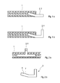
- Fig. 1a,b
- einen Schaum mit einem in den Schaum eingesetzten Flansch, bei verschiedenen Ausführungsformen,
- Fig. 2a
- einen Schaum mit darin eingesetzter und integral damit ausgebildeten Halterung,
- Fig. 2b
- die Halterung zum Einsetzen und Integrieren in den Schaum,
- Fig. 3
- eine Verstärkung des Schaums in einem stärker belasteten Bereich,
- Fig. 4a-c
- eine innenseitig offen poröse und außenseitig geschlossene Struktur, bei verschiedenen Ausführungsformen.
- Wie in
Fig. 1a dargestellt, kann in einen Schaum 1 ein Anbindungselement 2 eingelassen sein. Dabei kann das Anbindungselement 2 als Schweißborde 3 oder wie inFig. 1b dargestellt, als Schweißflansch 4 ausgebildet sein. - Ebenso ist es denkbar, wie in
Fig. 2a gezeigt, den Schaum 1 mit einer in denselben eingelassenen Halterung 5 als Anbindungselement 2 zu versehen. Bevorzugt ist dabei der Kopplungsbereich 6 des Anbindungselementes 2 mit einer Oberflächenkontur 7 ausgestattet. Diese Oberflächenkontur kann, wie inFig. 2b dargestellt, als eine Art Wellenform ausgebildet sein, es können aber auch an dem Kopplungsbereich 6 Haken, Ösen, Abzweigungen oder dergleichen ausgebildet sein. - Bevorzugt ist der Kopplungsbereich 6 mit dem restlichen Anbindungselement aus demselben Material ausgebildet. Besonders bevorzugt ist zumindest die Oberfläche des Kopplungsbereiches 6 offenporig ausgebildet und ganz besonders bevorzugt ist der Kopplungsbereich 6 offenporig und zumindest teilweise offen porös ausgebildet.
- Durch eine derartige offenporige bzw. offen poröse Ausbildung ist ein Eindringen des Schaums in den Kopplungsbereich 6 ermöglicht, wodurch eine stabilere Anbindung des Kopplungsbereichs an den Schaum 1 gelingt. Dies ist ebenfalls im Falle von Ösen gegeben.
- Wie in
Fig. 3 gezeigt, ist der Schaum 1 bevorzugt in einem stärker belasteten Bereich 8, wie in diesem Fall an einer Biegung, mit einer Verstärkung 9 ausgestattet. Diese Verstärkung 9 kann eine Verstärkung der radialen Dicke des Materials darstellen oder es ist auch denkbar, dass in diesem Bereich weniger Treibmittel der Schaumrohmasse beigemischt wird, sodass der Anteil an Nichttreibmittel in diesem stark belasteten Bereich höher ist und somit zu einer erhöhten Stabilität des Bereiches beiträgt. Demzufolge wird nach dem Ausbacken der Schaumrohmasse die Verstärkung 9 eine höhere Dichte aufweisen. Besonders bevorzugt weist in einem solchen, stärker belasteten Bereich 8 die Verstärkung 9 eine höhere radiale Dicke und/oder Dichte auf. - In
Fig. 4a ist eine zweischichtige Schaumstruktur 13 dargestellt, die außen eine Außenschicht 10 aus einem geschlossen porösen Schaum 1 und innen eine Innenschicht 11 aus einem offen porösen Schaum 12 aufweist. Durch eine derartige Materialverpaarung kann mittels Schalldämpfung durch den innenseitig angeordneten offen porösen Schaum 12 eine verbesserten Akustik einer Abgasanlage erreicht werden. Die geschlossenporige Außenschicht 10 sorgt für die erforderliche Gasdichtigkeit und erfüllt eine Tragfunktion für die offenporige Innenschicht 11. - Die Innenseite ist der Abgasströmung ausgesetzt. Um an der offenporigen Innenseite die Reibung bzw. den Strömungswiderstand zu reduzieren, kann es gemäß
Fig. 4b und 4c zweckmäßig sein, eine dreischichtige Schaumstruktur 13 vorzusehen. Bei der Variante derFig. 4b ist die Außenschicht 10 wieder aus einem geschlossenporigen Schaum 1 hergestellt und die aus einem offenporigen Schaum 12 hergestellte Innenschicht 11 ist an ihrer Innenseite mit einer weiteren Schicht 14 versehen, die im Folgenden als Auskleidungsschicht 14 bezeichnet wird. Die Auskleidungsschicht 14 ist ebenfalls aus einem offenporigen Schaum 12' hergestellt, der jedoch eine kleinere Porengröße aufweist als der offenporige Schaum 12 der Innenschicht 11. Die Auskleidungsschicht 14 besitzt somit einen reduzierten Strömungswiderstand und ist für Luftschall durchlässig, auf dessen Bedämpfung die dahinterliegende Innenschicht 11 hinsichtlich der Porengröße ihres Schaums 12 ausgelegt ist. - Bei der Variante der
Fig. 4c ist die Außenschicht 10 durch ein massives, also nicht geschäumtes Rohr 15 gebildet. Die Innenschicht 11 besteht aus dem offenporigen Schaum 12 mit größerer Porengröße. Die Auskleidungsschicht 14 besteht aus dem offenporigen Schaum 12' mit der kleineren Poregröße. Bei gleicher Tragfunktion wie der geschlossenporige Schaum 1 besitzt das Rohr 15 eine deutlich reduzierte Wandstärke, wodurch die durch die Schaumstruktur 13 gebildete Wand bei gleicher Tragkraft eine reduzierte Wandstärke aufweist. - Es ist klar, dass die geschichtete Schaumstruktur 13 auch mehr als drei Schichten aufweisen kann.
Claims (10)
- Komponente einer Abgasanlage für eine Brennkraftmaschine, insbesondere eines Kraftfahrzeugs, die zumindest in Teilbereichen einen selbsttragenden Mantel aufweist, der einen porösen, zellular aufgebauten Schaum (1) aufweist, wobei der Schaum (1) selbsttragend ausgebildet ist.
- Komponente nach Anspruch 1,
dadurch gekennzeichnet, dass
der Schaum (1) geschlossenporig ausgestaltet ist und/oder eine Schicht einer mehrschichtigen Schaumstruktur (13) bildet, die mindestens eine Schicht aus einem offenporigen Schaum (12) und/oder mindestens eine Schicht aus einem geschlossenporigen Schaum (1) aufweist. - Komponente nach Anspruch 1 oder 2,
dadurch gekennzeichnet, dass
der Mantel zumindest teilweise einen nichtporösen Außenoberflächenbereich und/oder einen nichtporösen Innenoberflächenbereich aufweist, wobei insbesondere vorgesehen sein kann, dass der Außenoberflächenbereich und/oder der Innenoberflächenbereich aus einem Rohr ausgebildet ist/sind, wobei der Schaum auf den Außenoberflächenbereich und/oder den Innenoberflächenbereich aufgebacken sein kann. - Komponente nach Anspruch 3,
dadurch gekennzeichnet, dass
der Innenoberflächenbereich und/oder der Außenoberflächenbereich integral mit und/oder aus dem Schaum (1) ausgebildet ist/sind. - Komponente nach einem oder mehreren der vorhergehenden Ansprüche,
dadurch gekennzeichnet,
dass der Schaum (1) aus Metall und/oder aus einem mineralischen Material besteht und/oder dass das Material des Mantels in zumindest zwei Bereichen eine unterschiedliche Dichte und/oder ein unterschiedliches Material und/oder eine unterschiedliche Wandstärke aufweist. - Komponente nach einem der vorhergehenden Ansprüche,
dadurch gekennzeichnet,
dass der Mantel eine Schaumstruktur (13) aufweist, die eine Außenschicht (10), eine innen an die Außenschicht (10) angrenzende Innenschicht (11) aus einem offenporigen Schaum (12) und eine innen an die Innenschicht (11) angrenzende Auskleidungsschicht (14) ebenfalls aus einem offenporigen Schaum (12') aufweist, wobei der offenporige Schaum (12') der Auskleidungsschicht (14) eine kleinere Poregroße aufweist als der offenporige Schaum (12) der Innenschicht (11), wobei insbesondere vorgesehen sein kann, dass die Außenschicht (19) aus einem geschlossenporigen Schaum (1) oder aus einem nicht-porösen Rohr (15) gebildet ist. - Komponente nach einem oder mehreren der vorhergehenden Ansprüche,
dadurch gekennzeichnet, dass
der Mantel innenseitig zumindest bereichsweise einen offenporigen Schaum (1) aufweist. - Komponente nach einem oder mehreren der vorhergehenden Ansprüche, dadurch gekennzeichnet, dass
der Mantel zumindest ein Anbindungselement (2,3,4,5) aufweist, das integral mit demselben ausgebildet ist. - Abgasanlage mit zumindest einer Komponente nach einem oder mehreren der vorhergehenden Ansprüche.
- Verfahren zur Herstellung einer Komponente einer Abgasanlage,
bei dem ein Mantel der Komponente durch Ausbacken einer Schaumrohmasse hergestellt wird, wobei der Schaumrohmasse in zumindest zwei Bereichen des zukünftigen Mantels ein Treibmittel in unterschiedlicher Konzentration beigemischt wird, so dass der Mantel in zumindest diesen zwei Bereichen nach dem Ausbacken eine unterschiedliche Dichte und/oder eine unterschiedliche Materialstärke aufweist.
Applications Claiming Priority (1)
| Application Number | Priority Date | Filing Date | Title |
|---|---|---|---|
| DE102010031855A DE102010031855A1 (de) | 2010-07-22 | 2010-07-22 | Abgasanlage |
Publications (2)
| Publication Number | Publication Date |
|---|---|
| EP2410148A1 true EP2410148A1 (de) | 2012-01-25 |
| EP2410148B1 EP2410148B1 (de) | 2014-05-21 |
Family
ID=44525560
Family Applications (1)
| Application Number | Title | Priority Date | Filing Date |
|---|---|---|---|
| EP11168434.6A Not-in-force EP2410148B1 (de) | 2010-07-22 | 2011-06-01 | Abgasanlage |
Country Status (3)
| Country | Link |
|---|---|
| US (1) | US8783414B2 (de) |
| EP (1) | EP2410148B1 (de) |
| DE (1) | DE102010031855A1 (de) |
Cited By (1)
| Publication number | Priority date | Publication date | Assignee | Title |
|---|---|---|---|---|
| WO2014147136A1 (de) * | 2013-03-20 | 2014-09-25 | Tenneco Gmbh | Flanschplatte |
Families Citing this family (7)
| Publication number | Priority date | Publication date | Assignee | Title |
|---|---|---|---|---|
| WO2012093480A1 (ja) * | 2011-01-06 | 2012-07-12 | イビデン株式会社 | 排ガス処理装置 |
| US9790836B2 (en) | 2012-11-20 | 2017-10-17 | Tenneco Automotive Operating Company, Inc. | Loose-fill insulation exhaust gas treatment device and methods of manufacturing |
| US20140206471A1 (en) * | 2013-01-22 | 2014-07-24 | Karsten Manufacturing Corporation | Variable density golf club grips |
| JP6541938B2 (ja) * | 2013-05-14 | 2019-07-10 | 株式会社ジェイエスピー | ダクト |
| US9545820B2 (en) * | 2014-10-31 | 2017-01-17 | GM Global Technology Operations LLC | Wheel with aluminum foam for tire cavity noise suppression |
| FR3103517B1 (fr) * | 2019-11-22 | 2021-10-29 | Faurecia Systemes Dechappement | Dispositif de chauffage de gaz d’échappement à élément chauffant en mousse métallique |
| DE102020115717B4 (de) | 2020-06-15 | 2024-02-15 | Volkswagen Aktiengesellschaft | Abgasnachbehandlungskomponente und Abgasnachbehandlungssystem |
Citations (9)
| Publication number | Priority date | Publication date | Assignee | Title |
|---|---|---|---|---|
| JPS58104318A (ja) * | 1981-12-14 | 1983-06-21 | Toyota Motor Corp | 断熱排気管 |
| EP0216729A1 (de) * | 1985-08-16 | 1987-04-01 | Alusuisse-Lonza Services Ag | Filterkerze zur Reinigung der Abgase von Dieselmotoren |
| EP0261050A2 (de) * | 1986-09-16 | 1988-03-23 | Lanxide Technology Company, Lp. | Poröses keramisches Verbundmaterial mit dichter Oberfläche |
| US5067584A (en) * | 1990-04-25 | 1991-11-26 | Williams William H | Low cost replaceable type sound dampening unit for vacuum cleaning machine |
| EP0867605A1 (de) * | 1997-03-29 | 1998-09-30 | Elring Klinger GmbH | Abgaskrümmer für Kraftfahrzeuge |
| DE10244798A1 (de) * | 2002-09-26 | 2004-04-01 | Daimlerchrysler Ag | Gasführende Leitung, insbesondere für eine Brennkraftmaschine |
| EP1507072A2 (de) * | 2003-08-13 | 2005-02-16 | DaimlerChrysler AG | Abgasführende Vorrichtung eines Verbrennungsmotors mit poröser Auskleidung |
| DE102007026123A1 (de) * | 2007-06-05 | 2008-12-11 | Volkswagen Ag | Zylinderkopf einer Brennkraftmaschine |
| EP2009132A1 (de) * | 2007-06-29 | 2008-12-31 | Sulzer Markets and Technology AG | Verfahren zur Herstellung einer funktionalen Schicht, Beschichtungsmaterial, Verfahren zu seiner Herstellung sowie funktionale Schicht |
Family Cites Families (31)
| Publication number | Priority date | Publication date | Assignee | Title |
|---|---|---|---|---|
| ZA717136B (en) * | 1970-11-06 | 1972-07-26 | Dunlop Holdings Ltd | Pressure reducing device |
| US4027476A (en) * | 1973-10-15 | 1977-06-07 | Rocket Research Corporation | Composite catalyst bed and method for making the same |
| DE2516626C2 (de) * | 1975-04-16 | 1977-04-28 | Freudenberg Carl Fa | Schalldaempfer fuer ausstroemende druckgase |
| US4015683A (en) * | 1975-12-29 | 1977-04-05 | Purex Corporation Ltd. | Noise suppressor for vacuum sweeper and the like |
| US4316523A (en) * | 1980-06-04 | 1982-02-23 | Boretti Napoleon P | Silencer for gas discharge devices |
| DE3220023C2 (de) * | 1982-05-27 | 1993-05-27 | Cellofoam Deutschland Gmbh, 7950 Biberach | Schalldämpfender Strömungskanal und Verfahren zu seiner Herstellung |
| US4713277A (en) * | 1985-07-19 | 1987-12-15 | Agency Of Industrial Science And Technology | Foamed metal and method of producing same |
| US5266143A (en) * | 1987-02-10 | 1993-11-30 | C.S.P. Centro Studi E Prototipi S.R.L. | Soundproofing panels for automobile applications and manufacturing processes therefor |
| US5400830A (en) * | 1992-11-12 | 1995-03-28 | Ford Motor Company | Composite automotive exhaust pipe |
| CH687167A5 (de) * | 1992-12-18 | 1996-09-30 | Matec Holding Ag | Laermmindernde Kapselung. |
| US5559310A (en) * | 1995-04-26 | 1996-09-24 | Ingersoll-Rand Company | Muffler for air operated reciprocating pumps |
| ES2224330T3 (es) * | 1998-01-30 | 2005-03-01 | Cww-Gerko Akustik Gmbh | Placa sandwich amortiguadora de sonidos. |
| JP2000220467A (ja) * | 1999-01-28 | 2000-08-08 | Tokai Rubber Ind Ltd | 低吸水・低吸油性防音材 |
| US6196351B1 (en) * | 1999-06-04 | 2001-03-06 | Lancaster Glass Fibre Limited | Silencer cartridge |
| US6109387A (en) * | 1999-07-19 | 2000-08-29 | Boretti; Napoleon P. | Silencer for gas discharge devices |
| GB0019913D0 (en) * | 2000-08-15 | 2000-09-27 | Ventures & Consultancy Bradfor | Sound absorbing material |
| JP4514967B2 (ja) * | 2001-01-11 | 2010-07-28 | 三恵技研工業株式会社 | エンジン用マフラおよびその製造方法 |
| US20020153199A1 (en) * | 2001-02-09 | 2002-10-24 | Schroer Daniel R. | Sound absorbing foam |
| ATE302339T1 (de) * | 2001-11-21 | 2005-09-15 | Dunlop Aerospace Ltd | Anordnung zur schalldämpfung |
| US6875066B2 (en) * | 2003-02-28 | 2005-04-05 | Polymer Technologies, Inc. | Sound insulation for outboard motors |
| ES2313128T3 (es) * | 2003-10-31 | 2009-03-01 | Dow Global Technologies Inc. | Sistema de aislamiento de sonido. |
| DE102005006234B4 (de) * | 2005-02-10 | 2007-07-19 | Carcoustics Tech Center Gmbh | Selbsttragende, Luftschall absorbierende Motorraumverkleidung für Kraftfahrzeuge |
| US7546899B2 (en) * | 2005-10-05 | 2009-06-16 | Arrowhead Products Corporation | Lightweight polymer muffler apparatus and method of making same |
| DE102006009134B4 (de) * | 2006-02-24 | 2016-03-24 | Bayer Materialscience Aktiengesellschaft | Verbessertes Verfahren zur Herstellung einer leichten, schallisolierenden Verkleidung für Kraftfahrzeuge und entsprechende Verkleidung |
| DE102006027230A1 (de) * | 2006-06-09 | 2007-12-20 | EFA -Entwicklungsgesellschaft für Akustik mbH | Akustisch und thermisch wirkende Isolation |
| US8051950B2 (en) * | 2006-08-03 | 2011-11-08 | Glacier Bay, Inc. | System for reducing acoustic energy |
| DE102007020832B4 (de) * | 2007-05-02 | 2009-02-26 | Bayer Materialscience Ag | Leichte, schallisolierende Verkleidung für ein Karosserieteil eines Kraftfahrzeuges und Verfahren zu deren Herstellung |
| DE102007045266A1 (de) * | 2007-09-21 | 2009-04-02 | Hydac Technology Gmbh | Dämpfungseinrichtung, insbesondere Pulsationsdämpfer |
| DE102007000568A1 (de) * | 2007-10-24 | 2009-04-30 | Silencesolutions Gmbh | Schallabsorber |
| GB2465364B (en) * | 2008-11-13 | 2011-03-30 | Thermo Fisher Scient | Enclosure,assembly and method for reducing noise from a pump |
| US8256569B1 (en) * | 2010-10-04 | 2012-09-04 | Huff Dennis L | Exhaust sound attenuation device and method of use |
-
2010
- 2010-07-22 DE DE102010031855A patent/DE102010031855A1/de not_active Withdrawn
-
2011
- 2011-06-01 EP EP11168434.6A patent/EP2410148B1/de not_active Not-in-force
- 2011-07-19 US US13/185,615 patent/US8783414B2/en active Active
Patent Citations (9)
| Publication number | Priority date | Publication date | Assignee | Title |
|---|---|---|---|---|
| JPS58104318A (ja) * | 1981-12-14 | 1983-06-21 | Toyota Motor Corp | 断熱排気管 |
| EP0216729A1 (de) * | 1985-08-16 | 1987-04-01 | Alusuisse-Lonza Services Ag | Filterkerze zur Reinigung der Abgase von Dieselmotoren |
| EP0261050A2 (de) * | 1986-09-16 | 1988-03-23 | Lanxide Technology Company, Lp. | Poröses keramisches Verbundmaterial mit dichter Oberfläche |
| US5067584A (en) * | 1990-04-25 | 1991-11-26 | Williams William H | Low cost replaceable type sound dampening unit for vacuum cleaning machine |
| EP0867605A1 (de) * | 1997-03-29 | 1998-09-30 | Elring Klinger GmbH | Abgaskrümmer für Kraftfahrzeuge |
| DE10244798A1 (de) * | 2002-09-26 | 2004-04-01 | Daimlerchrysler Ag | Gasführende Leitung, insbesondere für eine Brennkraftmaschine |
| EP1507072A2 (de) * | 2003-08-13 | 2005-02-16 | DaimlerChrysler AG | Abgasführende Vorrichtung eines Verbrennungsmotors mit poröser Auskleidung |
| DE102007026123A1 (de) * | 2007-06-05 | 2008-12-11 | Volkswagen Ag | Zylinderkopf einer Brennkraftmaschine |
| EP2009132A1 (de) * | 2007-06-29 | 2008-12-31 | Sulzer Markets and Technology AG | Verfahren zur Herstellung einer funktionalen Schicht, Beschichtungsmaterial, Verfahren zu seiner Herstellung sowie funktionale Schicht |
Cited By (2)
| Publication number | Priority date | Publication date | Assignee | Title |
|---|---|---|---|---|
| WO2014147136A1 (de) * | 2013-03-20 | 2014-09-25 | Tenneco Gmbh | Flanschplatte |
| US10202885B2 (en) | 2013-03-20 | 2019-02-12 | Tenneco Gmbh | Flange plate |
Also Published As
| Publication number | Publication date |
|---|---|
| EP2410148B1 (de) | 2014-05-21 |
| US8783414B2 (en) | 2014-07-22 |
| DE102010031855A1 (de) | 2012-01-26 |
| US20120017565A1 (en) | 2012-01-26 |
Similar Documents
| Publication | Publication Date | Title |
|---|---|---|
| EP2410148B1 (de) | Abgasanlage | |
| EP2514939B1 (de) | Abgasanlagenkomponente mit thermischer Isolierung | |
| EP0807749B1 (de) | Abgasanlage für ein Kraftfahrzeug sowie Kraftfahrzeug | |
| WO1997009134A1 (de) | Verstärktes formteil, verfahren zu seiner herstellung und seine verwendung | |
| DE102007010486A1 (de) | Abgasnachbehandlungseinrichtung eines Kraftfahrzeugs | |
| DE102017220297B4 (de) | Wärmetauscher | |
| DE102007008823A1 (de) | Katalysatorträgerkörper | |
| DE102012110707B4 (de) | Abgasturboladerbaugruppe mit integrierter Isolierlage | |
| DE69701698T2 (de) | Hydrierungreaktor und-verfahren | |
| DE102009008799A1 (de) | Kraftfahrzeug | |
| DE102010031853A1 (de) | Abgasanlage | |
| EP3018412A1 (de) | Rekuperator und Rekuperatorbrenner | |
| WO2006072414A1 (de) | Wabenkörper mit zumindest teilweise keramischer wabenstruktur und aufnahme für messfühler und verfahren zur herstellung eines solchen wabenkörpers | |
| DE102008031083A1 (de) | Verdampferbaugruppe für einen Verdampferbrenner eines Heizgerätes, insbesondere für ein Fahrzeug | |
| DE10357125A1 (de) | Krümmer für eine Abgasanlage und Verfahren zur Herstellung eines Krümmers | |
| EP1507072A2 (de) | Abgasführende Vorrichtung eines Verbrennungsmotors mit poröser Auskleidung | |
| EP1837497B1 (de) | Abgasnachbehandlungssystem umfassend einen Speicherkatalysator und einen Partikelfilter sowie Verfahren zur Herstellung eines derartigen Systems | |
| DE102008052631A1 (de) | Gasdynamische Druckwellenmaschine | |
| DE102009008299A1 (de) | Verfahren zur Herstellung eines keramischen Filterelements und Filterelement | |
| DE10244798A1 (de) | Gasführende Leitung, insbesondere für eine Brennkraftmaschine | |
| DE102004053916B4 (de) | Abgasleitung sowie Verfahren zur Herstellung einer Abgasleitung | |
| DE102008031657A1 (de) | Abgaskonverter zur katalytischen Nachbehandlung verbrennungsmotorischer Abgase sowie Abgasanlage enthaltend einen solchen | |
| DE102006041584B4 (de) | Verfahren zur Herstellung eines Wälzlagerbauteils in Form eines Wälzkörpers oder eines Wälzlagerrings mit wälzfester Oberfläche und schwingungsdämpfendem Kern | |
| DE102005020963B4 (de) | Abgaskatalysator für eine Brennkraftmaschine | |
| DE102006008782A1 (de) | Abgasleitungssystem |
Legal Events
| Date | Code | Title | Description |
|---|---|---|---|
| AK | Designated contracting states |
Kind code of ref document: A1 Designated state(s): AL AT BE BG CH CY CZ DE DK EE ES FI FR GB GR HR HU IE IS IT LI LT LU LV MC MK MT NL NO PL PT RO RS SE SI SK SM TR |
|
| AX | Request for extension of the european patent |
Extension state: BA ME |
|
| PUAI | Public reference made under article 153(3) epc to a published international application that has entered the european phase |
Free format text: ORIGINAL CODE: 0009012 |
|
| 17P | Request for examination filed |
Effective date: 20120725 |
|
| 17Q | First examination report despatched |
Effective date: 20121016 |
|
| RAP1 | Party data changed (applicant data changed or rights of an application transferred) |
Owner name: EBERSPAECHER EXHAUST TECHNOLOGY GMBH & CO. KG |
|
| GRAP | Despatch of communication of intention to grant a patent |
Free format text: ORIGINAL CODE: EPIDOSNIGR1 |
|
| INTG | Intention to grant announced |
Effective date: 20140226 |
|
| GRAS | Grant fee paid |
Free format text: ORIGINAL CODE: EPIDOSNIGR3 |
|
| GRAA | (expected) grant |
Free format text: ORIGINAL CODE: 0009210 |
|
| AK | Designated contracting states |
Kind code of ref document: B1 Designated state(s): AL AT BE BG CH CY CZ DE DK EE ES FI FR GB GR HR HU IE IS IT LI LT LU LV MC MK MT NL NO PL PT RO RS SE SI SK SM TR |
|
| REG | Reference to a national code |
Ref country code: GB Ref legal event code: FG4D Free format text: NOT ENGLISH |
|
| REG | Reference to a national code |
Ref country code: CH Ref legal event code: EP |
|
| REG | Reference to a national code |
Ref country code: AT Ref legal event code: REF Ref document number: 669722 Country of ref document: AT Kind code of ref document: T Effective date: 20140615 |
|
| REG | Reference to a national code |
Ref country code: IE Ref legal event code: FG4D Free format text: LANGUAGE OF EP DOCUMENT: GERMAN |
|
| REG | Reference to a national code |
Ref country code: DE Ref legal event code: R096 Ref document number: 502011003176 Country of ref document: DE Effective date: 20140626 |
|
| REG | Reference to a national code |
Ref country code: SE Ref legal event code: TRGR |
|
| REG | Reference to a national code |
Ref country code: NL Ref legal event code: VDEP Effective date: 20140521 |
|
| REG | Reference to a national code |
Ref country code: LT Ref legal event code: MG4D |
|
| PG25 | Lapsed in a contracting state [announced via postgrant information from national office to epo] |
Ref country code: LT Free format text: LAPSE BECAUSE OF FAILURE TO SUBMIT A TRANSLATION OF THE DESCRIPTION OR TO PAY THE FEE WITHIN THE PRESCRIBED TIME-LIMIT Effective date: 20140521 Ref country code: IS Free format text: LAPSE BECAUSE OF FAILURE TO SUBMIT A TRANSLATION OF THE DESCRIPTION OR TO PAY THE FEE WITHIN THE PRESCRIBED TIME-LIMIT Effective date: 20140921 Ref country code: FI Free format text: LAPSE BECAUSE OF FAILURE TO SUBMIT A TRANSLATION OF THE DESCRIPTION OR TO PAY THE FEE WITHIN THE PRESCRIBED TIME-LIMIT Effective date: 20140521 Ref country code: NO Free format text: LAPSE BECAUSE OF FAILURE TO SUBMIT A TRANSLATION OF THE DESCRIPTION OR TO PAY THE FEE WITHIN THE PRESCRIBED TIME-LIMIT Effective date: 20140821 Ref country code: GR Free format text: LAPSE BECAUSE OF FAILURE TO SUBMIT A TRANSLATION OF THE DESCRIPTION OR TO PAY THE FEE WITHIN THE PRESCRIBED TIME-LIMIT Effective date: 20140822 |
|
| PG25 | Lapsed in a contracting state [announced via postgrant information from national office to epo] |
Ref country code: RS Free format text: LAPSE BECAUSE OF FAILURE TO SUBMIT A TRANSLATION OF THE DESCRIPTION OR TO PAY THE FEE WITHIN THE PRESCRIBED TIME-LIMIT Effective date: 20140521 Ref country code: HR Free format text: LAPSE BECAUSE OF FAILURE TO SUBMIT A TRANSLATION OF THE DESCRIPTION OR TO PAY THE FEE WITHIN THE PRESCRIBED TIME-LIMIT Effective date: 20140521 Ref country code: ES Free format text: LAPSE BECAUSE OF FAILURE TO SUBMIT A TRANSLATION OF THE DESCRIPTION OR TO PAY THE FEE WITHIN THE PRESCRIBED TIME-LIMIT Effective date: 20140521 Ref country code: LV Free format text: LAPSE BECAUSE OF FAILURE TO SUBMIT A TRANSLATION OF THE DESCRIPTION OR TO PAY THE FEE WITHIN THE PRESCRIBED TIME-LIMIT Effective date: 20140521 Ref country code: PL Free format text: LAPSE BECAUSE OF FAILURE TO SUBMIT A TRANSLATION OF THE DESCRIPTION OR TO PAY THE FEE WITHIN THE PRESCRIBED TIME-LIMIT Effective date: 20140521 |
|
| PG25 | Lapsed in a contracting state [announced via postgrant information from national office to epo] |
Ref country code: PT Free format text: LAPSE BECAUSE OF FAILURE TO SUBMIT A TRANSLATION OF THE DESCRIPTION OR TO PAY THE FEE WITHIN THE PRESCRIBED TIME-LIMIT Effective date: 20140922 |
|
| PG25 | Lapsed in a contracting state [announced via postgrant information from national office to epo] |
Ref country code: DK Free format text: LAPSE BECAUSE OF FAILURE TO SUBMIT A TRANSLATION OF THE DESCRIPTION OR TO PAY THE FEE WITHIN THE PRESCRIBED TIME-LIMIT Effective date: 20140521 Ref country code: SK Free format text: LAPSE BECAUSE OF FAILURE TO SUBMIT A TRANSLATION OF THE DESCRIPTION OR TO PAY THE FEE WITHIN THE PRESCRIBED TIME-LIMIT Effective date: 20140521 Ref country code: RO Free format text: LAPSE BECAUSE OF FAILURE TO SUBMIT A TRANSLATION OF THE DESCRIPTION OR TO PAY THE FEE WITHIN THE PRESCRIBED TIME-LIMIT Effective date: 20140521 Ref country code: CZ Free format text: LAPSE BECAUSE OF FAILURE TO SUBMIT A TRANSLATION OF THE DESCRIPTION OR TO PAY THE FEE WITHIN THE PRESCRIBED TIME-LIMIT Effective date: 20140521 Ref country code: EE Free format text: LAPSE BECAUSE OF FAILURE TO SUBMIT A TRANSLATION OF THE DESCRIPTION OR TO PAY THE FEE WITHIN THE PRESCRIBED TIME-LIMIT Effective date: 20140521 |
|
| REG | Reference to a national code |
Ref country code: CH Ref legal event code: PL |
|
| REG | Reference to a national code |
Ref country code: DE Ref legal event code: R097 Ref document number: 502011003176 Country of ref document: DE |
|
| PG25 | Lapsed in a contracting state [announced via postgrant information from national office to epo] |
Ref country code: NL Free format text: LAPSE BECAUSE OF FAILURE TO SUBMIT A TRANSLATION OF THE DESCRIPTION OR TO PAY THE FEE WITHIN THE PRESCRIBED TIME-LIMIT Effective date: 20140521 |
|
| REG | Reference to a national code |
Ref country code: IE Ref legal event code: MM4A |
|
| PLBE | No opposition filed within time limit |
Free format text: ORIGINAL CODE: 0009261 |
|
| STAA | Information on the status of an ep patent application or granted ep patent |
Free format text: STATUS: NO OPPOSITION FILED WITHIN TIME LIMIT |
|
| 26N | No opposition filed |
Effective date: 20150224 |
|
| PG25 | Lapsed in a contracting state [announced via postgrant information from national office to epo] |
Ref country code: CH Free format text: LAPSE BECAUSE OF NON-PAYMENT OF DUE FEES Effective date: 20140630 Ref country code: LI Free format text: LAPSE BECAUSE OF NON-PAYMENT OF DUE FEES Effective date: 20140630 Ref country code: IE Free format text: LAPSE BECAUSE OF NON-PAYMENT OF DUE FEES Effective date: 20140601 |
|
| REG | Reference to a national code |
Ref country code: DE Ref legal event code: R097 Ref document number: 502011003176 Country of ref document: DE Effective date: 20150224 |
|
| PG25 | Lapsed in a contracting state [announced via postgrant information from national office to epo] |
Ref country code: SI Free format text: LAPSE BECAUSE OF FAILURE TO SUBMIT A TRANSLATION OF THE DESCRIPTION OR TO PAY THE FEE WITHIN THE PRESCRIBED TIME-LIMIT Effective date: 20140521 |
|
| PG25 | Lapsed in a contracting state [announced via postgrant information from national office to epo] |
Ref country code: MT Free format text: LAPSE BECAUSE OF FAILURE TO SUBMIT A TRANSLATION OF THE DESCRIPTION OR TO PAY THE FEE WITHIN THE PRESCRIBED TIME-LIMIT Effective date: 20140521 |
|
| PG25 | Lapsed in a contracting state [announced via postgrant information from national office to epo] |
Ref country code: MC Free format text: LAPSE BECAUSE OF FAILURE TO SUBMIT A TRANSLATION OF THE DESCRIPTION OR TO PAY THE FEE WITHIN THE PRESCRIBED TIME-LIMIT Effective date: 20140521 Ref country code: SM Free format text: LAPSE BECAUSE OF FAILURE TO SUBMIT A TRANSLATION OF THE DESCRIPTION OR TO PAY THE FEE WITHIN THE PRESCRIBED TIME-LIMIT Effective date: 20140521 |
|
| REG | Reference to a national code |
Ref country code: FR Ref legal event code: PLFP Year of fee payment: 6 |
|
| PG25 | Lapsed in a contracting state [announced via postgrant information from national office to epo] |
Ref country code: CY Free format text: LAPSE BECAUSE OF FAILURE TO SUBMIT A TRANSLATION OF THE DESCRIPTION OR TO PAY THE FEE WITHIN THE PRESCRIBED TIME-LIMIT Effective date: 20140521 Ref country code: BG Free format text: LAPSE BECAUSE OF FAILURE TO SUBMIT A TRANSLATION OF THE DESCRIPTION OR TO PAY THE FEE WITHIN THE PRESCRIBED TIME-LIMIT Effective date: 20140521 |
|
| PG25 | Lapsed in a contracting state [announced via postgrant information from national office to epo] |
Ref country code: TR Free format text: LAPSE BECAUSE OF FAILURE TO SUBMIT A TRANSLATION OF THE DESCRIPTION OR TO PAY THE FEE WITHIN THE PRESCRIBED TIME-LIMIT Effective date: 20140521 Ref country code: LU Free format text: LAPSE BECAUSE OF NON-PAYMENT OF DUE FEES Effective date: 20140601 Ref country code: BE Free format text: LAPSE BECAUSE OF FAILURE TO SUBMIT A TRANSLATION OF THE DESCRIPTION OR TO PAY THE FEE WITHIN THE PRESCRIBED TIME-LIMIT Effective date: 20140630 Ref country code: HU Free format text: LAPSE BECAUSE OF FAILURE TO SUBMIT A TRANSLATION OF THE DESCRIPTION OR TO PAY THE FEE WITHIN THE PRESCRIBED TIME-LIMIT; INVALID AB INITIO Effective date: 20110601 |
|
| REG | Reference to a national code |
Ref country code: FR Ref legal event code: PLFP Year of fee payment: 7 |
|
| PG25 | Lapsed in a contracting state [announced via postgrant information from national office to epo] |
Ref country code: AT Free format text: LAPSE BECAUSE OF FAILURE TO SUBMIT A TRANSLATION OF THE DESCRIPTION OR TO PAY THE FEE WITHIN THE PRESCRIBED TIME-LIMIT Effective date: 20140521 |
|
| REG | Reference to a national code |
Ref country code: AT Ref legal event code: MM01 Ref document number: 669722 Country of ref document: AT Kind code of ref document: T Effective date: 20160601 |
|
| PG25 | Lapsed in a contracting state [announced via postgrant information from national office to epo] |
Ref country code: AT Free format text: LAPSE BECAUSE OF FAILURE TO SUBMIT A TRANSLATION OF THE DESCRIPTION OR TO PAY THE FEE WITHIN THE PRESCRIBED TIME-LIMIT Effective date: 20160601 |
|
| REG | Reference to a national code |
Ref country code: FR Ref legal event code: PLFP Year of fee payment: 8 |
|
| PG25 | Lapsed in a contracting state [announced via postgrant information from national office to epo] |
Ref country code: MK Free format text: LAPSE BECAUSE OF FAILURE TO SUBMIT A TRANSLATION OF THE DESCRIPTION OR TO PAY THE FEE WITHIN THE PRESCRIBED TIME-LIMIT Effective date: 20140521 |
|
| PG25 | Lapsed in a contracting state [announced via postgrant information from national office to epo] |
Ref country code: AL Free format text: LAPSE BECAUSE OF FAILURE TO SUBMIT A TRANSLATION OF THE DESCRIPTION OR TO PAY THE FEE WITHIN THE PRESCRIBED TIME-LIMIT Effective date: 20140521 |
|
| PG25 | Lapsed in a contracting state [announced via postgrant information from national office to epo] |
Ref country code: IT Free format text: LAPSE BECAUSE OF NON-PAYMENT OF DUE FEES Effective date: 20190601 |
|
| REG | Reference to a national code |
Ref country code: DE Ref legal event code: R081 Ref document number: 502011003176 Country of ref document: DE Owner name: PUREM GMBH, DE Free format text: FORMER OWNER: EBERSPAECHER EXHAUST TECHNOLOGY GMBH & CO. KG, 66539 NEUNKIRCHEN, DE |
|
| PGFP | Annual fee paid to national office [announced via postgrant information from national office to epo] |
Ref country code: SE Payment date: 20220623 Year of fee payment: 12 |
|
| REG | Reference to a national code |
Ref country code: SE Ref legal event code: EUG |
|
| PG25 | Lapsed in a contracting state [announced via postgrant information from national office to epo] |
Ref country code: SE Free format text: LAPSE BECAUSE OF NON-PAYMENT OF DUE FEES Effective date: 20230602 |
|
| PGFP | Annual fee paid to national office [announced via postgrant information from national office to epo] |
Ref country code: GB Payment date: 20240620 Year of fee payment: 14 |
|
| PGFP | Annual fee paid to national office [announced via postgrant information from national office to epo] |
Ref country code: DE Payment date: 20240617 Year of fee payment: 14 |
|
| PGFP | Annual fee paid to national office [announced via postgrant information from national office to epo] |
Ref country code: FR Payment date: 20240617 Year of fee payment: 14 |
|
| REG | Reference to a national code |
Ref country code: DE Ref legal event code: R119 Ref document number: 502011003176 Country of ref document: DE |
|
| GBPC | Gb: european patent ceased through non-payment of renewal fee |
Effective date: 20250601 |
|
| PG25 | Lapsed in a contracting state [announced via postgrant information from national office to epo] |
Ref country code: GB Free format text: LAPSE BECAUSE OF NON-PAYMENT OF DUE FEES Effective date: 20250601 |
|
| PG25 | Lapsed in a contracting state [announced via postgrant information from national office to epo] |
Ref country code: DE Free format text: LAPSE BECAUSE OF NON-PAYMENT OF DUE FEES Effective date: 20260101 |
|
| PG25 | Lapsed in a contracting state [announced via postgrant information from national office to epo] |
Ref country code: FR Free format text: LAPSE BECAUSE OF NON-PAYMENT OF DUE FEES Effective date: 20250630 |