EP2409909B1 - Moment and magnet detecting equipment for an electric bicycle - Google Patents
Moment and magnet detecting equipment for an electric bicycle Download PDFInfo
- Publication number
- EP2409909B1 EP2409909B1 EP20100169987 EP10169987A EP2409909B1 EP 2409909 B1 EP2409909 B1 EP 2409909B1 EP 20100169987 EP20100169987 EP 20100169987 EP 10169987 A EP10169987 A EP 10169987A EP 2409909 B1 EP2409909 B1 EP 2409909B1
- Authority
- EP
- European Patent Office
- Prior art keywords
- transmitting
- plate
- driving
- teeth
- assembly
- Prior art date
- Legal status (The legal status is an assumption and is not a legal conclusion. Google has not performed a legal analysis and makes no representation as to the accuracy of the status listed.)
- Not-in-force
Links
Images


Classifications
-
- B—PERFORMING OPERATIONS; TRANSPORTING
- B62—LAND VEHICLES FOR TRAVELLING OTHERWISE THAN ON RAILS
- B62M—RIDER PROPULSION OF WHEELED VEHICLES OR SLEDGES; POWERED PROPULSION OF SLEDGES OR SINGLE-TRACK CYCLES; TRANSMISSIONS SPECIALLY ADAPTED FOR SUCH VEHICLES
- B62M6/00—Rider propulsion of wheeled vehicles with additional source of power, e.g. combustion engine or electric motor
- B62M6/40—Rider propelled cycles with auxiliary electric motor
- B62M6/45—Control or actuating devices therefor
- B62M6/50—Control or actuating devices therefor characterised by detectors or sensors, or arrangement thereof
-
- G—PHYSICS
- G01—MEASURING; TESTING
- G01L—MEASURING FORCE, STRESS, TORQUE, WORK, MECHANICAL POWER, MECHANICAL EFFICIENCY, OR FLUID PRESSURE
- G01L3/00—Measuring torque, work, mechanical power, or mechanical efficiency, in general
- G01L3/02—Rotary-transmission dynamometers
- G01L3/14—Rotary-transmission dynamometers wherein the torque-transmitting element is other than a torsionally-flexible shaft
- G01L3/1407—Rotary-transmission dynamometers wherein the torque-transmitting element is other than a torsionally-flexible shaft involving springs
- G01L3/1428—Rotary-transmission dynamometers wherein the torque-transmitting element is other than a torsionally-flexible shaft involving springs using electrical transducers
- G01L3/1435—Rotary-transmission dynamometers wherein the torque-transmitting element is other than a torsionally-flexible shaft involving springs using electrical transducers involving magnetic or electromagnetic means
Definitions
- the present invention relates to a moment and magnet detecting equipment of an electric bicycle, and more particularly to a moment and magnet detecting equipment of an electric bicycle having magnetic sensors to detect the driving moment and adjust an exporting power of a motor of the electric bicycle.
- a conventional moment and magnet detecting equipment of an electric bicycle is set in a bottom bracket of a bicycle and has two Hall effect sensors, two magnetic plates, a controller, a motor and other complex components.
- the Hall effect sensors detect the magnetic plates and gain a driving moment data of a crank of the bicycle.
- a controller of the moment and magnet detecting equipment of an electric bicycle adjusts an outputting power from a motor of the bicycle to support of the user.
- the components of the conventional moment and magnet detecting of an electric bicycle are complex and not easy to set in the bottom bracket.
- the bottom bracket of a normal frame of the electric bicycle can not contain the moment and magnet detecting equipment of an electric bicycle and need to be refitted. The refitting process of the bicycle is difficult, complex and not easy.
- the present invention tends to provide a moment and magnet detecting equipment of an electric bicycle to mitigate or obviate the aforementioned problems.
- EP 0 935 128 A1 is related to an auxiliary powered manpowered vehicle having a torque detector that detects the torque applied to a rotated crank axle in a non-contact manner.
- the manpowered vehicle includes a main body, a rotated body supported by the main body and driven by manpower, a rotary coil arranged coaxially with the rotated body, a variable impedance device electrically connected to the rotary coil and having its impedance varied in accordance with the load applied to the rotated body
- EP 0 965 828 A2 relates to an input torque detecting apparatus for a power assist vehicle, including a first rotator which is rotated in synchronization with rotation of input operating members manually operated for rotating a drive wheel, and a second rotator which is disposed coaxially with the first rotator with an elastic member interposed between the first rotator and the second rotator and which is rotated in synchronization with rotation of the drive wheel, wherein an input torque into the input operating members is detected on the basis of a rotational phase difference produced between the first and second rotators.
- the main objective of the present invention is to provide a moment and magnet detecting equipment of an electric bicycle having magnetic sensors to detect the driving moment and adjust an outputting power of a motor of the electric bicycle.
- the moment and magnet detecting equipment of an electric bicycle is set between a bottom bracket and a crank of a bicycle and has a transmitting assembly, a driving assembly and a fixing assembly.
- the transmitting assembly is mounted on a chain wheel and has an outer loop mounted in an inner side of the transmitting assembly.
- the driving assembly is mounted around and rotated by a rotating shaft of the bicycle connected to the crank and is mounted in and rotates the transmitting assembly and has an inner loop mounted in an inner side of the driving assembly.
- the fixing assembly is fixed on the bottom bracket and has an outer magnetic sensor and an inner magnetic sensor respectively detecting with the outer magnets and the inner magnets.
- a moment and magnet detecting equipment of an electric bicycle in accordance with the present invention has a transmitting assembly 10, a driving assembly 20 and a fixing assembly 30.
- the transmitting assembly 10 has a transmitting plate 11 and an outer loop 12.
- the transmitting plate 11 may be quadrilateral, pentagonal, hexagonal or polygonal and has an attaching side, a mounting side, multiple corners, a center, multiple threaded holes 111, a mounting recess 112, multiple transmitting teeth 113 and a center hole 114.
- the transmitting plate 11 is pentagonal and has five corners, five threaded holes 111 any five transmitting teeth 113 to fit with the pentagonal transmitting plate 11.
- the threaded holes 111 are respectively formed through the five corners of the transmitting plate 11 at same intervals and arranged in a circle around the center of the transmitting plate 11.
- the radiuses of the threaded holes 111 are the same.
- the mounting recess 112 is circular and formed in the inner side and around the center of the transmitting plate 11.
- the transmitting teeth 113 are radially formed on the inner side of the transmitting plate 11 in the mounting recess 112, are located at same intervals and protrude toward the center of the transmitting plate 11, and may be three, four or multiple in the amount.
- Each transmitting tooth 113 is cubic and has a front side and a rear side opposite to each other.
- the center hole 114 is circular and formed through the center of the transmitting plate 11 and has an inner diameter.
- the outer loop 12 is mounted in the inner side around the center hole 114 of the transmitting plate 11, is arranged between the threaded holes 111 and the mounting recess 112 and is fastened by screws and has multiple outer magnets 121.
- the outer magnets 121 are mounted around the outer loop 12 at same intervals.
- the outer magnets 121 are twelve in the embodiment and may be ten or eight.
- the driving assembly 20 is mounted in the transmitting plate 11 and has a driving plate 21, a bearing 22, multiple springs 23, an inner loop 24 and a cover loop 25.
- the driving plate 21 is mounted in the mounting recess 112 surrounded by the transmitting teeth 113 and has an inner side, an outer side, an outer ring edge, a shaft hole 211, a bearing groove 212, multiple driving teeth 213 and a cylinder 214.
- the shaft hole 211 is rectangular and formed through the driving plate 21 and has an inner diameter shorter than the inner diameter of the center hole 114 of the transmitting plate 11.
- the bearing groove 212 is formed in the inner side of the driving plate 21 around the shaft hole 211.
- the driving teeth 213 are radially formed on and protruding from the outer ring edge of the driving plate 21, are located at same intervals and respectively press against and correspond to the transmitting teeth 113 of the transmitting plate 11.
- Each driving tooth 213 is cubic and has an abutting side abutting the front side of the corresponded transmitting tooth 113 and a pressing side opposite to the abutting side.
- the driving teeth 213 may be three, four or multiple in the amount according to the transmitting teeth 113.
- the cylinder 214 protrudes from the outer surface of the driving plate 21 and rotatably inserted into the center hole 114 of the transmitting plate 11.
- the bearing 22 is mounted in the bearing groove 212 of the driving plate 21.
- the springs 23 are respectively mounted between the transmitting teeth 113 of the transmitting plate 11 and the driving teeth 213 of the driving plate 21 in the mounting recess 112.
- Each spring 23 has two ends respectively abutting the rear side of one of the transmitting tooth 113 and the spring side of one of the driving teeth 213 next to the transmitting tooth 113.
- the springs 23 may be four, five, six or multiple according to the amount of the transmitting teeth 113 and the driving teeth 213.
- the inner loop 24 is mounted in the inner side of the driving plate 21 and fastened by screws and has twelve outer magnets 241.
- the outer magnets 241 are mounted around the inner loop 24, are located at same intervals and are respectively aligned to and correspond to the outer magnets 121 of the outer loop 12.
- the cover loop 25 is mounted on the inner surface of the driving plate 21 and covers and keeps the transmitting teeth 113, the driving teeth 213 and the springs 23 in the mounting recess 112 of the transmitting plate 11.
- the outer magnets 241 are twelve in the embodiment and may be ten or eight according to and correspond to the inner magnets 121.
- the fixing assembly 30 faces the transmitting assembly 10 and the driving assembly 20 and has a fixing plate 31. an outer magnetic sensor 32 and an inner magnetic sensor 33.
- the fixing plate 31 faces the driving plate 21 and covers the mounting recess 112 and the outer loop 12 and has a covering surface, a fixing surface, a through hole 311, a mounting tube 312. a setting recess 313 and a fixing recess 314.
- the covering surface of the fixing plate 31 faces the transmitting assembly 10 and covers the mounting recess 112 and the outer loop 12.
- the through hole 311 is formed through the fixing plate 31 and communicates with the shaft hole 211 of the driving plate 21.
- the mounting tube 312 is formed on and protrude from the inner surface of the fixing plate 31 around the through hole 311 and is inserted into the bearing groove 212 to surround and cover the bearing 22.
- the setting recess 313 is formed in the inner surface of the fixing plate 31.
- the fixing recess 314 is rectangular and formed in the outer surface of the fixing plate 31 around the through hole 311.
- the outer magnetic sensor 32 is mounted in the setting recess 313 and aligned with the inner loop 24 and faces and reacts with the outer magnets 241.
- the inner magnetic sensor 33 is mounted in the setting recess 313 and aligned with the outer loop 12 and faces and reacts with the inner magnets 121.
- the outer magnetic sensor 32 and the inner magnetic sensor 33 may be Hall effect sensors.
- the moment and magnet detecting equipment of an electric bicycle is mounted on the electric bicycle.
- the electric bicycle has a chain wheel 40, a bottom bracket 41, two end covers 42, a rotating shaft 43 and crank 44.
- the bottom bracket 41 is implemented on a frame of the electric bicycle.
- the end covers 42 are respectively mounted opposite on the bottom bracket 41 and each has a fixing protrusion shaped in cubic.
- the rotating shaft 43 is rotatably mounted through the bottom bracket 41 and extends out from the end covers 42 and has a connecting end.
- the chain wheel 40 is connected to the moment and magnet detecting equipment of an electric bicycle and mounted around the connecting end of the rotating shaft 43.
- the crank 44 has a pivoting end being mounted on the connecting end of the rotating shaft 43.
- the moment and magnet detecting equipment of an electric bicycle is set between the bottom bracket 41 and the chain wheel 40 and has simple compositions and may be set easily and conveniently.
- the user steps the foot pedals of the bicycle to rotate the crank 44 and drive the rotating shaft 43.
- the rotating shaft 43 is rotated to rotate the driving plate 21.
- the driving teeth 213 of the driving plate 21 are rotated to press the springs 23 and push the transmitting teeth 113 of the transmitting plate 11 and rotate the transmitting plate 11. Because the transmitting plate 11 is mounted on the chain wheel 40, the chain wheel 40 is driven to rotate and make the electric bicycle working.
- the outer loop 12 and the inner loop 24 are driven to rotate with the transmitting assembly 10 and the driving assembly 20.
- the outer magnets 121 on the outer loop 12 and the outer magnets 241 on the inner loop 24 are respectively passed through the inner magnetic sensor 33 and the outer magnetic sensor 32 and excite potentials.
- the crank 44 is rotated by an increasing driving moment, a rotating moment of the driving teeth 213 of the driving plate 21 will increase accordingly. This indicates that the user is in a strenuous situation. Therefore, the driving plate 21 is rotated faster than the transmitting plate 11.
- the time of each outer magnets 241passing through the outer magnetic sensor 32 is earlier than the time of the corresponded outer magnet 121passing through the inner magnetic sensor 33. According to the change of the potential between the outer magnetic sensor 32 and the inner magnetic sensor 33, a motor of the electric bicycle is driven to output more power to rotate the chain wheel 40 and make the user relax.
Description
- The present invention relates to a moment and magnet detecting equipment of an electric bicycle, and more particularly to a moment and magnet detecting equipment of an electric bicycle having magnetic sensors to detect the driving moment and adjust an exporting power of a motor of the electric bicycle.
- A conventional moment and magnet detecting equipment of an electric bicycle is set in a bottom bracket of a bicycle and has two Hall effect sensors, two magnetic plates, a controller, a motor and other complex components. The Hall effect sensors detect the magnetic plates and gain a driving moment data of a crank of the bicycle. According to the driving moment data, a controller of the moment and magnet detecting equipment of an electric bicycle adjusts an outputting power from a motor of the bicycle to support of the user.
- However, the components of the conventional moment and magnet detecting of an electric bicycle are complex and not easy to set in the bottom bracket. Furthermore, the bottom bracket of a normal frame of the electric bicycle can not contain the moment and magnet detecting equipment of an electric bicycle and need to be refitted. The refitting process of the bicycle is difficult, complex and not easy.
- To overcome the shortcomings, the present invention tends to provide a moment and magnet detecting equipment of an electric bicycle to mitigate or obviate the aforementioned problems.
-
EP 0 935 128 A1 -
EP 0 965 828 A2 - The main objective of the present invention is to provide a moment and magnet detecting equipment of an electric bicycle having magnetic sensors to detect the driving moment and adjust an outputting power of a motor of the electric bicycle.
- The moment and magnet detecting equipment of an electric bicycle is set between a bottom bracket and a crank of a bicycle and has a transmitting assembly, a driving assembly and a fixing assembly. The transmitting assembly is mounted on a chain wheel and has an outer loop mounted in an inner side of the transmitting assembly. The driving assembly is mounted around and rotated by a rotating shaft of the bicycle connected to the crank and is mounted in and rotates the transmitting assembly and has an inner loop mounted in an inner side of the driving assembly. The fixing assembly is fixed on the bottom bracket and has an outer magnetic sensor and an inner magnetic sensor respectively detecting with the outer magnets and the inner magnets.
- Other objects, advantages and novel features of the invention will become more apparent from the following detailed description when taken in junction with the accompanying drawings.
-
-
Fig. 1 is a perspective view of a moment and magnet detecting equipment of an electric bicycle in accordance with the present invention; -
Fig. 2 is an exploded perspective of the interacting equipment of the electric bicycle inFig. 1 showing the outer side; -
Fig. 3 is an exploded perspective of the interacting equipment of the electric bicycle inFig. 1 showing the inner side; -
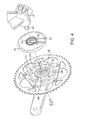
Fig. 4 is a partially exploded perspective view of the interacting equipment of the electric bicycle inFig. 1 showing the inner side; -
Fig. 5 is an enlarged cross sectional side view of the interacting equipment of the electric bicycle inFig. 1 : -
Fig. 6 is a side view of the interacting equipment of the electric bicycle inFig. 1 showing the outer side; -
Fig. 7 is a partially exploded side view of the interacting equipment of the electric bicycle inFig. 1 showing the outer side; and -
Fig. 8 is a partially exploded side view of the interacting equipment of the electric bicycle inFig. 1 showing the operation. - With reference to
Figs. 1 to 5 and7 , a moment and magnet detecting equipment of an electric bicycle in accordance with the present invention has atransmitting assembly 10, adriving assembly 20 and afixing assembly 30. - The transmitting
assembly 10 has a transmittingplate 11 and anouter loop 12. The transmittingplate 11 may be quadrilateral, pentagonal, hexagonal or polygonal and has an attaching side, a mounting side, multiple corners, a center, multiple threadedholes 111, a mounting recess 112, multiple transmittingteeth 113 and acenter hole 114. In one embodiment of the present invention, thetransmitting plate 11 is pentagonal and has five corners, five threadedholes 111 any five transmittingteeth 113 to fit with thepentagonal transmitting plate 11. - The threaded
holes 111 are respectively formed through the five corners of thetransmitting plate 11 at same intervals and arranged in a circle around the center of the transmittingplate 11. The radiuses of the threadedholes 111 are the same. Themounting recess 112 is circular and formed in the inner side and around the center of thetransmitting plate 11. - The transmitting
teeth 113 are radially formed on the inner side of thetransmitting plate 11 in themounting recess 112, are located at same intervals and protrude toward the center of thetransmitting plate 11, and may be three, four or multiple in the amount. Each transmittingtooth 113 is cubic and has a front side and a rear side opposite to each other. Thecenter hole 114 is circular and formed through the center of thetransmitting plate 11 and has an inner diameter. - The
outer loop 12 is mounted in the inner side around thecenter hole 114 of thetransmitting plate 11, is arranged between the threadedholes 111 and the mounting recess 112 and is fastened by screws and has multipleouter magnets 121. Theouter magnets 121 are mounted around theouter loop 12 at same intervals. Theouter magnets 121 are twelve in the embodiment and may be ten or eight. - The
driving assembly 20 is mounted in thetransmitting plate 11 and has adriving plate 21, abearing 22,multiple springs 23, aninner loop 24 and acover loop 25. Thedriving plate 21 is mounted in themounting recess 112 surrounded by thetransmitting teeth 113 and has an inner side, an outer side, an outer ring edge, ashaft hole 211, abearing groove 212,multiple driving teeth 213 and acylinder 214. Theshaft hole 211 is rectangular and formed through thedriving plate 21 and has an inner diameter shorter than the inner diameter of thecenter hole 114 of thetransmitting plate 11. Thebearing groove 212 is formed in the inner side of thedriving plate 21 around theshaft hole 211. - The driving
teeth 213 are radially formed on and protruding from the outer ring edge of thedriving plate 21, are located at same intervals and respectively press against and correspond to the transmittingteeth 113 of thetransmitting plate 11. Eachdriving tooth 213 is cubic and has an abutting side abutting the front side of the corresponded transmittingtooth 113 and a pressing side opposite to the abutting side. Thedriving teeth 213 may be three, four or multiple in the amount according to the transmittingteeth 113. Thecylinder 214 protrudes from the outer surface of thedriving plate 21 and rotatably inserted into thecenter hole 114 of thetransmitting plate 11. - The
bearing 22 is mounted in thebearing groove 212 of thedriving plate 21. Thesprings 23 are respectively mounted between the transmittingteeth 113 of thetransmitting plate 11 and thedriving teeth 213 of thedriving plate 21 in themounting recess 112. Eachspring 23 has two ends respectively abutting the rear side of one of the transmittingtooth 113 and the spring side of one of the drivingteeth 213 next to the transmittingtooth 113. Thesprings 23 may be four, five, six or multiple according to the amount of the transmittingteeth 113 and thedriving teeth 213. - The
inner loop 24 is mounted in the inner side of thedriving plate 21 and fastened by screws and has twelveouter magnets 241. Theouter magnets 241 are mounted around theinner loop 24, are located at same intervals and are respectively aligned to and correspond to theouter magnets 121 of theouter loop 12. Thecover loop 25 is mounted on the inner surface of thedriving plate 21 and covers and keeps thetransmitting teeth 113, thedriving teeth 213 and thesprings 23 in themounting recess 112 of thetransmitting plate 11. Theouter magnets 241 are twelve in the embodiment and may be ten or eight according to and correspond to theinner magnets 121. - The
fixing assembly 30 faces thetransmitting assembly 10 and thedriving assembly 20 and has afixing plate 31. an outermagnetic sensor 32 and an innermagnetic sensor 33. Thefixing plate 31 faces thedriving plate 21 and covers the mounting recess 112 and theouter loop 12 and has a covering surface, a fixing surface, a throughhole 311, amounting tube 312. asetting recess 313 and afixing recess 314. - The covering surface of the
fixing plate 31 faces the transmittingassembly 10 and covers themounting recess 112 and theouter loop 12. The throughhole 311 is formed through thefixing plate 31 and communicates with theshaft hole 211 of thedriving plate 21. The mountingtube 312 is formed on and protrude from the inner surface of the fixingplate 31 around the throughhole 311 and is inserted into the bearinggroove 212 to surround and cover thebearing 22. Thesetting recess 313 is formed in the inner surface of the fixingplate 31. The fixingrecess 314 is rectangular and formed in the outer surface of the fixingplate 31 around the throughhole 311. - The outer
magnetic sensor 32 is mounted in thesetting recess 313 and aligned with theinner loop 24 and faces and reacts with theouter magnets 241. The innermagnetic sensor 33 is mounted in thesetting recess 313 and aligned with theouter loop 12 and faces and reacts with theinner magnets 121. The outermagnetic sensor 32 and the innermagnetic sensor 33 may be Hall effect sensors. - The moment and magnet detecting equipment of an electric bicycle is mounted on the electric bicycle. The electric bicycle has a
chain wheel 40, abottom bracket 41, two end covers 42, a rotatingshaft 43 and crank 44. Thebottom bracket 41 is implemented on a frame of the electric bicycle. The end covers 42 are respectively mounted opposite on thebottom bracket 41 and each has a fixing protrusion shaped in cubic. The rotatingshaft 43 is rotatably mounted through thebottom bracket 41 and extends out from the end covers 42 and has a connecting end. Thechain wheel 40 is connected to the moment and magnet detecting equipment of an electric bicycle and mounted around the connecting end of therotating shaft 43. Thecrank 44 has a pivoting end being mounted on the connecting end of therotating shaft 43. - In assembling, using five screws to insert through the threaded
holes 111 of the transmittingplate 11 and screw into thechain wheel 40 to connect the transmittingplate 11 on thechain wheel 40. The connecting end of therotating shaft 43 is inserted through the throughhole 311 of the fixingplate 31, theshaft hole 211 of the drivingplate 21 and thecenter hole 114 of the transmittingplate 11, and connected to the pivoting end of thecrank 44. The pivoting end of thecrank 44 abuts thecylinder 214 of the drivingplate 21. The fixing protrusion of the one of the end covers 42 is mounted into the fixingrecess 314 of the fixingplate 31 to fix the fixingassembly 30 from rotating. - Because the moment and magnet detecting equipment of an electric bicycle is set between the
bottom bracket 41 and thechain wheel 40 and has simple compositions and may be set easily and conveniently. - With reference to
Figs. 1 and6 to 8 , in use, the user steps the foot pedals of the bicycle to rotate the crank 44 and drive the rotatingshaft 43. The rotatingshaft 43 is rotated to rotate the drivingplate 21. The drivingteeth 213 of the drivingplate 21 are rotated to press thesprings 23 and push the transmittingteeth 113 of the transmittingplate 11 and rotate the transmittingplate 11. Because the transmittingplate 11 is mounted on thechain wheel 40, thechain wheel 40 is driven to rotate and make the electric bicycle working. - When the transmitting
assembly 10 and the drivingassembly 20 are rotated, theouter loop 12 and theinner loop 24 are driven to rotate with the transmittingassembly 10 and the drivingassembly 20. Theouter magnets 121 on theouter loop 12 and theouter magnets 241 on theinner loop 24 are respectively passed through the innermagnetic sensor 33 and the outermagnetic sensor 32 and excite potentials. - If the
crank 44 is rotated by an increasing driving moment, a rotating moment of the drivingteeth 213 of the drivingplate 21 will increase accordingly. This indicates that the user is in a strenuous situation. Therefore, the drivingplate 21 is rotated faster than the transmittingplate 11. The time of each outer magnets 241passing through the outermagnetic sensor 32 is earlier than the time of the corresponded outer magnet 121passing through the innermagnetic sensor 33. According to the change of the potential between the outermagnetic sensor 32 and the innermagnetic sensor 33, a motor of the electric bicycle is driven to output more power to rotate thechain wheel 40 and make the user relax.
Claims (6)
- A moment and magnet detecting equipment for an electric bicycle, comprising a transmitting assembly (10), a driven assembly (20) and a fixing assembly (30) and wherein:the transmitting assembly (10) has
a transmitting plate (11) having
an attaching side;
a mounting side being opposite to the attaching side;
multiple comers;
a center;
multiple threaded holes (111) respectively formed through the corners of the transmitting plate(11);
a mounting recess (112) formed in the inner side and around the center of the transmitting plate (11);
multiple transmitting teeth (113) radially formed on the inner side of the transmitting plate (11) in the mounting recess (112) and protruding toward the center of the transmitting plate (11); and
a center hole (114) formed through the center of the transmitting plate (11); and
an outer loop (12) mounted in the inner side around the center hole (114) and having multiple outer magnets (121) mounted around the outer loop (12);the driving assembly (20) is mounted in the transmitting plate (11) and has
a driving plate (21) mounted in the mounting recess (112) and having
an inner side;
an outer side being opposite to the inner side;
an outer ring edge;
a shaft hole (211) formed through the driving plate;
a bearing groove (212) formed in the inner side of the driving plate (21) around the shaft hole (211);
multiple driving teeth (213) radially formed on and protruding from the outer ring edge of the driving plate (21) and respectively corresponding to the transmitting teeth (113);
a bearing (22) mounted in the bearing groove (212) of the driving plate (21);
multiple springs (23) respectively mounted between the corresponded transmitting teeth (113) and the driving teeth (213); and
an inner loop (24) mounted in the inner side of the driving plate (21) and having multiple inner magnets (241) mounted around the inner loop (24);the fixing assembly (30) faces the transmitting assembly (10) and the driving assembly (20) and has
a fixing plate (31) covering the mounting recess (112) and the outer loop (12) and having
a covering surface facing the transmitting assembly (10);
a fixing surface being opposite to the covering surface;
a through hole (311) formed through the fixing plate (31);
a mounting tube (312) formed on and protruding from the inner surface of the fixing plate (31) around the through hole (311) and inserted into the bearing groove (212) to mount around and cover the bearing (22); and
a fixing recess (314) formed in the outer surface of the fixing plate (31) around the through hole (311); and
an outer magnetic sensor (33) mounted in the covering surface of the fixing plate (31) and aligned with the outer loop (12) and detecting the outer magnets (121); and
an inner magnetic sensor (32) mounted in the covering surface of the fixing plate (31) and aligned with the inner loop (24) and detecting the inner magnets (241). - The moment and magnet detecting equipment for an electric bicycle as claimed in claim 1, wherein
each transmitting tooth (113) has a same interval to the adjacent transmitting teeth (113);
the driving teeth (213) are located at same intervals; and
the driving assembly (20) further has a cover loop (25) mounted on the inner surface of the driving plate (21) and covering and keeping the transmitting teeth (113), the driving teeth (213) and the springs (23) in the mounting recess (112) of the transmitting plate (11). - The moment and magnet detecting equipment for an electric bicycle as claimed in claim 1 or 2, wherein
the center hole (114) is circular; and
the cylinder (214) protrudes from the outer surface of the driving plate (21) and is rotatably inserted into the center hole (114) of the transmitting plate (11). - The moment and magnet detecting equipment for an electric bicycle as claimed in claim 3, wherein the
the outer magnets (121) are according to and correspond to the inner magnets (241) in amount and position. - The moment and magnet detecting equipment for an electric bicycle as claimed in claim 4, wherein
the outer magnetic sensor (33) and the inner magnetic sensor (32) are respectively mounted in a setting recess (313). - The moment and magnet detecting equipment for an electric bicycle as claimed in
claim 5, wherein
the transmitting plate (11) is pentagonal and has
five comers;
five threaded holes (111) respectively formed through the corners of the transmitting plate (11); and
the transmitting teeth (113) and the driving teeth (213) are respectively implemented with five in amount;
the outer magnets (121) and the inner magnets (241) are respectively implemented with twelve in amount.
Priority Applications (1)
| Application Number | Priority Date | Filing Date | Title |
|---|---|---|---|
| EP20100169987 EP2409909B1 (en) | 2010-07-19 | 2010-07-19 | Moment and magnet detecting equipment for an electric bicycle |
Applications Claiming Priority (1)
| Application Number | Priority Date | Filing Date | Title |
|---|---|---|---|
| EP20100169987 EP2409909B1 (en) | 2010-07-19 | 2010-07-19 | Moment and magnet detecting equipment for an electric bicycle |
Publications (2)
| Publication Number | Publication Date |
|---|---|
| EP2409909A1 EP2409909A1 (en) | 2012-01-25 |
| EP2409909B1 true EP2409909B1 (en) | 2012-11-14 |
Family
ID=43027728
Family Applications (1)
| Application Number | Title | Priority Date | Filing Date |
|---|---|---|---|
| EP20100169987 Not-in-force EP2409909B1 (en) | 2010-07-19 | 2010-07-19 | Moment and magnet detecting equipment for an electric bicycle |
Country Status (1)
| Country | Link |
|---|---|
| EP (1) | EP2409909B1 (en) |
Families Citing this family (3)
| Publication number | Priority date | Publication date | Assignee | Title |
|---|---|---|---|---|
| TWI515145B (en) * | 2012-12-03 | 2016-01-01 | 黃永松 | Torque sensing gear structure of an electronic bike |
| GB201303776D0 (en) * | 2013-03-01 | 2013-04-17 | Karbon Kinetics Ltd | Non contact pedal crank torque for a bicycle |
| US20170113756A1 (en) * | 2014-06-18 | 2017-04-27 | Sunstar Giken Kabushiki Kaisha | Sensor for use in power-assisted mobile object, power-assisted unit, power-assisted mobile object, and torque detection method |
Family Cites Families (3)
| Publication number | Priority date | Publication date | Assignee | Title |
|---|---|---|---|---|
| DE19617959C1 (en) * | 1996-05-06 | 1997-10-23 | Werner K Dipl Ing Mayer | Pedal force detection device for bicycle with electric motor |
| JP3163046B2 (en) * | 1996-10-25 | 2001-05-08 | 三洋電機株式会社 | Man-powered vehicle with auxiliary power |
| JP2000002604A (en) * | 1998-06-18 | 2000-01-07 | Honda Motor Co Ltd | Input torque detecting device of power-assisted vehicle |
-
2010
- 2010-07-19 EP EP20100169987 patent/EP2409909B1/en not_active Not-in-force
Also Published As
| Publication number | Publication date |
|---|---|
| EP2409909A1 (en) | 2012-01-25 |
Similar Documents
| Publication | Publication Date | Title |
|---|---|---|
| US20130162112A1 (en) | Motor-Gear Unit | |
| US8650972B2 (en) | Sensor apparatus for a bicycle hub | |
| US9273947B2 (en) | Sensing magnet apparatus for motor | |
| EP2873601B1 (en) | Electric bicycle and control method thereof | |
| JP5479436B2 (en) | Torque detection device | |
| TWI424938B (en) | Motor assisted rotating eel mechanism | |
| EP2409909B1 (en) | Moment and magnet detecting equipment for an electric bicycle | |
| US20140305727A1 (en) | Bicycle drive unit | |
| US20200186008A1 (en) | Electric power tool | |
| EP2479099A1 (en) | Power output device for vehicle | |
| EP2549137A2 (en) | Traction motor | |
| WO2018205713A1 (en) | Electric bicycle torque sensing-type motor and electric bicycle | |
| WO2015074426A1 (en) | Wheel hub motor and method for using same | |
| JP2003095181A (en) | Power assisted bicycle | |
| TWM553291U (en) | Bicycle derailleur unit | |
| EP3480104B1 (en) | Crank drive motor for electric bicycle with automatic gear shifting | |
| CN111295325B (en) | Electric drive device for a bicycle | |
| JP2004067039A (en) | Hub motor unit | |
| US20170191886A1 (en) | Torque detecting device | |
| CN114302845B (en) | Bicycle driving system and kit | |
| EP4155182A1 (en) | Power module of electric assisted bicycle | |
| JP2003095179A (en) | Electrically assisted bicycle | |
| EP3480103A1 (en) | Crank drive motor assembly for electric bicycle | |
| JP2012020692A (en) | Treading moment transmission sensing device for power-assisted bicycle | |
| JP2003164110A (en) | Drive motor for motor-assisted bicycle |
Legal Events
| Date | Code | Title | Description |
|---|---|---|---|
| 17P | Request for examination filed |
Effective date: 20110413 |
|
| AK | Designated contracting states |
Kind code of ref document: A1 Designated state(s): AL AT BE BG CH CY CZ DE DK EE ES FI FR GB GR HR HU IE IS IT LI LT LU LV MC MK MT NL NO PL PT RO SE SI SK SM TR |
|
| AX | Request for extension of the european patent |
Extension state: BA ME RS |
|
| PUAI | Public reference made under article 153(3) epc to a published international application that has entered the european phase |
Free format text: ORIGINAL CODE: 0009012 |
|
| RIC1 | Information provided on ipc code assigned before grant |
Ipc: G01L 3/14 20060101ALI20120131BHEP Ipc: B62M 6/50 20100101AFI20120131BHEP |
|
| GRAP | Despatch of communication of intention to grant a patent |
Free format text: ORIGINAL CODE: EPIDOSNIGR1 |
|
| RIN1 | Information on inventor provided before grant (corrected) |
Inventor name: HUANG, SAN-I Inventor name: LIN, CHENG-YUAN Inventor name: FANG, SEN-HSIEN Inventor name: CHEN, HONG-FANG |
|
| GRAS | Grant fee paid |
Free format text: ORIGINAL CODE: EPIDOSNIGR3 |
|
| GRAA | (expected) grant |
Free format text: ORIGINAL CODE: 0009210 |
|
| AK | Designated contracting states |
Kind code of ref document: B1 Designated state(s): AL AT BE BG CH CY CZ DE DK EE ES FI FR GB GR HR HU IE IS IT LI LT LU LV MC MK MT NL NO PL PT RO SE SI SK SM TR |
|
| REG | Reference to a national code |
Ref country code: GB Ref legal event code: FG4D |
|
| REG | Reference to a national code |
Ref country code: AT Ref legal event code: REF Ref document number: 583826 Country of ref document: AT Kind code of ref document: T Effective date: 20121115 Ref country code: CH Ref legal event code: EP Ref country code: CH Ref legal event code: NV Representative=s name: SCHNEIDER FELDMANN AG PATENT- UND MARKENANWAEL, CH |
|
| REG | Reference to a national code |
Ref country code: IE Ref legal event code: FG4D |
|
| REG | Reference to a national code |
Ref country code: DE Ref legal event code: R096 Ref document number: 602010003586 Country of ref document: DE Effective date: 20130110 |
|
| REG | Reference to a national code |
Ref country code: SE Ref legal event code: TRGR |
|
| REG | Reference to a national code |
Ref country code: NL Ref legal event code: T3 |
|
| REG | Reference to a national code |
Ref country code: AT Ref legal event code: MK05 Ref document number: 583826 Country of ref document: AT Kind code of ref document: T Effective date: 20121114 |
|
| REG | Reference to a national code |
Ref country code: LT Ref legal event code: MG4D |
|
| PG25 | Lapsed in a contracting state [announced via postgrant information from national office to epo] |
Ref country code: HR Free format text: LAPSE BECAUSE OF FAILURE TO SUBMIT A TRANSLATION OF THE DESCRIPTION OR TO PAY THE FEE WITHIN THE PRESCRIBED TIME-LIMIT Effective date: 20121114 Ref country code: FI Free format text: LAPSE BECAUSE OF FAILURE TO SUBMIT A TRANSLATION OF THE DESCRIPTION OR TO PAY THE FEE WITHIN THE PRESCRIBED TIME-LIMIT Effective date: 20121114 Ref country code: ES Free format text: LAPSE BECAUSE OF FAILURE TO SUBMIT A TRANSLATION OF THE DESCRIPTION OR TO PAY THE FEE WITHIN THE PRESCRIBED TIME-LIMIT Effective date: 20130225 Ref country code: LT Free format text: LAPSE BECAUSE OF FAILURE TO SUBMIT A TRANSLATION OF THE DESCRIPTION OR TO PAY THE FEE WITHIN THE PRESCRIBED TIME-LIMIT Effective date: 20121114 Ref country code: NO Free format text: LAPSE BECAUSE OF FAILURE TO SUBMIT A TRANSLATION OF THE DESCRIPTION OR TO PAY THE FEE WITHIN THE PRESCRIBED TIME-LIMIT Effective date: 20130214 |
|
| PG25 | Lapsed in a contracting state [announced via postgrant information from national office to epo] |
Ref country code: BE Free format text: LAPSE BECAUSE OF FAILURE TO SUBMIT A TRANSLATION OF THE DESCRIPTION OR TO PAY THE FEE WITHIN THE PRESCRIBED TIME-LIMIT Effective date: 20121114 Ref country code: LV Free format text: LAPSE BECAUSE OF FAILURE TO SUBMIT A TRANSLATION OF THE DESCRIPTION OR TO PAY THE FEE WITHIN THE PRESCRIBED TIME-LIMIT Effective date: 20121114 Ref country code: PL Free format text: LAPSE BECAUSE OF FAILURE TO SUBMIT A TRANSLATION OF THE DESCRIPTION OR TO PAY THE FEE WITHIN THE PRESCRIBED TIME-LIMIT Effective date: 20121114 Ref country code: PT Free format text: LAPSE BECAUSE OF FAILURE TO SUBMIT A TRANSLATION OF THE DESCRIPTION OR TO PAY THE FEE WITHIN THE PRESCRIBED TIME-LIMIT Effective date: 20130314 Ref country code: SI Free format text: LAPSE BECAUSE OF FAILURE TO SUBMIT A TRANSLATION OF THE DESCRIPTION OR TO PAY THE FEE WITHIN THE PRESCRIBED TIME-LIMIT Effective date: 20121114 |
|
| PG25 | Lapsed in a contracting state [announced via postgrant information from national office to epo] |
Ref country code: AT Free format text: LAPSE BECAUSE OF FAILURE TO SUBMIT A TRANSLATION OF THE DESCRIPTION OR TO PAY THE FEE WITHIN THE PRESCRIBED TIME-LIMIT Effective date: 20121114 |
|
| PG25 | Lapsed in a contracting state [announced via postgrant information from national office to epo] |
Ref country code: BG Free format text: LAPSE BECAUSE OF FAILURE TO SUBMIT A TRANSLATION OF THE DESCRIPTION OR TO PAY THE FEE WITHIN THE PRESCRIBED TIME-LIMIT Effective date: 20130214 Ref country code: EE Free format text: LAPSE BECAUSE OF FAILURE TO SUBMIT A TRANSLATION OF THE DESCRIPTION OR TO PAY THE FEE WITHIN THE PRESCRIBED TIME-LIMIT Effective date: 20121114 Ref country code: DK Free format text: LAPSE BECAUSE OF FAILURE TO SUBMIT A TRANSLATION OF THE DESCRIPTION OR TO PAY THE FEE WITHIN THE PRESCRIBED TIME-LIMIT Effective date: 20121114 Ref country code: CZ Free format text: LAPSE BECAUSE OF FAILURE TO SUBMIT A TRANSLATION OF THE DESCRIPTION OR TO PAY THE FEE WITHIN THE PRESCRIBED TIME-LIMIT Effective date: 20121114 Ref country code: SK Free format text: LAPSE BECAUSE OF FAILURE TO SUBMIT A TRANSLATION OF THE DESCRIPTION OR TO PAY THE FEE WITHIN THE PRESCRIBED TIME-LIMIT Effective date: 20121114 |
|
| PG25 | Lapsed in a contracting state [announced via postgrant information from national office to epo] |
Ref country code: RO Free format text: LAPSE BECAUSE OF FAILURE TO SUBMIT A TRANSLATION OF THE DESCRIPTION OR TO PAY THE FEE WITHIN THE PRESCRIBED TIME-LIMIT Effective date: 20121114 Ref country code: IT Free format text: LAPSE BECAUSE OF FAILURE TO SUBMIT A TRANSLATION OF THE DESCRIPTION OR TO PAY THE FEE WITHIN THE PRESCRIBED TIME-LIMIT Effective date: 20121114 |
|
| PLBE | No opposition filed within time limit |
Free format text: ORIGINAL CODE: 0009261 |
|
| STAA | Information on the status of an ep patent application or granted ep patent |
Free format text: STATUS: NO OPPOSITION FILED WITHIN TIME LIMIT |
|
| 26N | No opposition filed |
Effective date: 20130815 |
|
| PG25 | Lapsed in a contracting state [announced via postgrant information from national office to epo] |
Ref country code: CY Free format text: LAPSE BECAUSE OF FAILURE TO SUBMIT A TRANSLATION OF THE DESCRIPTION OR TO PAY THE FEE WITHIN THE PRESCRIBED TIME-LIMIT Effective date: 20121114 |
|
| REG | Reference to a national code |
Ref country code: DE Ref legal event code: R097 Ref document number: 602010003586 Country of ref document: DE Effective date: 20130815 |
|
| PG25 | Lapsed in a contracting state [announced via postgrant information from national office to epo] |
Ref country code: MC Free format text: LAPSE BECAUSE OF FAILURE TO SUBMIT A TRANSLATION OF THE DESCRIPTION OR TO PAY THE FEE WITHIN THE PRESCRIBED TIME-LIMIT Effective date: 20121114 |
|
| REG | Reference to a national code |
Ref country code: IE Ref legal event code: MM4A |
|
| PG25 | Lapsed in a contracting state [announced via postgrant information from national office to epo] |
Ref country code: IE Free format text: LAPSE BECAUSE OF NON-PAYMENT OF DUE FEES Effective date: 20130719 |
|
| PG25 | Lapsed in a contracting state [announced via postgrant information from national office to epo] |
Ref country code: SM Free format text: LAPSE BECAUSE OF FAILURE TO SUBMIT A TRANSLATION OF THE DESCRIPTION OR TO PAY THE FEE WITHIN THE PRESCRIBED TIME-LIMIT Effective date: 20121114 |
|
| PG25 | Lapsed in a contracting state [announced via postgrant information from national office to epo] |
Ref country code: MT Free format text: LAPSE BECAUSE OF FAILURE TO SUBMIT A TRANSLATION OF THE DESCRIPTION OR TO PAY THE FEE WITHIN THE PRESCRIBED TIME-LIMIT Effective date: 20121114 Ref country code: TR Free format text: LAPSE BECAUSE OF FAILURE TO SUBMIT A TRANSLATION OF THE DESCRIPTION OR TO PAY THE FEE WITHIN THE PRESCRIBED TIME-LIMIT Effective date: 20121114 |
|
| PG25 | Lapsed in a contracting state [announced via postgrant information from national office to epo] |
Ref country code: LU Free format text: LAPSE BECAUSE OF NON-PAYMENT OF DUE FEES Effective date: 20130719 Ref country code: HU Free format text: LAPSE BECAUSE OF FAILURE TO SUBMIT A TRANSLATION OF THE DESCRIPTION OR TO PAY THE FEE WITHIN THE PRESCRIBED TIME-LIMIT; INVALID AB INITIO Effective date: 20100719 Ref country code: MK Free format text: LAPSE BECAUSE OF FAILURE TO SUBMIT A TRANSLATION OF THE DESCRIPTION OR TO PAY THE FEE WITHIN THE PRESCRIBED TIME-LIMIT Effective date: 20121114 |
|
| PG25 | Lapsed in a contracting state [announced via postgrant information from national office to epo] |
Ref country code: GR Free format text: LAPSE BECAUSE OF NON-PAYMENT OF DUE FEES Effective date: 20121114 |
|
| REG | Reference to a national code |
Ref country code: FR Ref legal event code: PLFP Year of fee payment: 7 |
|
| PG25 | Lapsed in a contracting state [announced via postgrant information from national office to epo] |
Ref country code: IS Free format text: LAPSE BECAUSE OF FAILURE TO SUBMIT A TRANSLATION OF THE DESCRIPTION OR TO PAY THE FEE WITHIN THE PRESCRIBED TIME-LIMIT Effective date: 20121114 |
|
| PGFP | Annual fee paid to national office [announced via postgrant information from national office to epo] |
Ref country code: GB Payment date: 20160523 Year of fee payment: 7 |
|
| PGFP | Annual fee paid to national office [announced via postgrant information from national office to epo] |
Ref country code: FR Payment date: 20160516 Year of fee payment: 7 |
|
| PGFP | Annual fee paid to national office [announced via postgrant information from national office to epo] |
Ref country code: NL Payment date: 20160721 Year of fee payment: 7 |
|
| PGFP | Annual fee paid to national office [announced via postgrant information from national office to epo] |
Ref country code: DE Payment date: 20160728 Year of fee payment: 7 |
|
| PGFP | Annual fee paid to national office [announced via postgrant information from national office to epo] |
Ref country code: SE Payment date: 20160721 Year of fee payment: 7 |
|
| PGFP | Annual fee paid to national office [announced via postgrant information from national office to epo] |
Ref country code: CH Payment date: 20161026 Year of fee payment: 7 |
|
| REG | Reference to a national code |
Ref country code: DE Ref legal event code: R119 Ref document number: 602010003586 Country of ref document: DE |
|
| REG | Reference to a national code |
Ref country code: CH Ref legal event code: PL |
|
| REG | Reference to a national code |
Ref country code: NL Ref legal event code: MM Effective date: 20170801 |
|
| REG | Reference to a national code |
Ref country code: SE Ref legal event code: EUG |
|
| GBPC | Gb: european patent ceased through non-payment of renewal fee |
Effective date: 20170719 |
|
| REG | Reference to a national code |
Ref country code: FR Ref legal event code: ST Effective date: 20180330 |
|
| PG25 | Lapsed in a contracting state [announced via postgrant information from national office to epo] |
Ref country code: SE Free format text: LAPSE BECAUSE OF NON-PAYMENT OF DUE FEES Effective date: 20170720 Ref country code: GB Free format text: LAPSE BECAUSE OF NON-PAYMENT OF DUE FEES Effective date: 20170719 Ref country code: CH Free format text: LAPSE BECAUSE OF NON-PAYMENT OF DUE FEES Effective date: 20170731 Ref country code: LI Free format text: LAPSE BECAUSE OF NON-PAYMENT OF DUE FEES Effective date: 20170731 Ref country code: NL Free format text: LAPSE BECAUSE OF NON-PAYMENT OF DUE FEES Effective date: 20170801 Ref country code: DE Free format text: LAPSE BECAUSE OF NON-PAYMENT OF DUE FEES Effective date: 20180201 |
|
| PG25 | Lapsed in a contracting state [announced via postgrant information from national office to epo] |
Ref country code: FR Free format text: LAPSE BECAUSE OF NON-PAYMENT OF DUE FEES Effective date: 20170731 |
|
| PG25 | Lapsed in a contracting state [announced via postgrant information from national office to epo] |
Ref country code: AL Free format text: LAPSE BECAUSE OF FAILURE TO SUBMIT A TRANSLATION OF THE DESCRIPTION OR TO PAY THE FEE WITHIN THE PRESCRIBED TIME-LIMIT Effective date: 20121114 |