EP2409880A1 - Occupant restraint device control device - Google Patents
Occupant restraint device control device Download PDFInfo
- Publication number
- EP2409880A1 EP2409880A1 EP10753517A EP10753517A EP2409880A1 EP 2409880 A1 EP2409880 A1 EP 2409880A1 EP 10753517 A EP10753517 A EP 10753517A EP 10753517 A EP10753517 A EP 10753517A EP 2409880 A1 EP2409880 A1 EP 2409880A1
- Authority
- EP
- European Patent Office
- Prior art keywords
- vehicle
- case
- electronic circuit
- circuit substrate
- spring structure
- Prior art date
- Legal status (The legal status is an assumption and is not a legal conclusion. Google has not performed a legal analysis and makes no representation as to the accuracy of the status listed.)
- Granted
Links
Images


Classifications
-
- H—ELECTRICITY
- H05—ELECTRIC TECHNIQUES NOT OTHERWISE PROVIDED FOR
- H05K—PRINTED CIRCUITS; CASINGS OR CONSTRUCTIONAL DETAILS OF ELECTRIC APPARATUS; MANUFACTURE OF ASSEMBLAGES OF ELECTRICAL COMPONENTS
- H05K5/00—Casings, cabinets or drawers for electric apparatus
- H05K5/0026—Casings, cabinets or drawers for electric apparatus provided with connectors and printed circuit boards [PCB], e.g. automotive electronic control units
- H05K5/0078—Casings, cabinets or drawers for electric apparatus provided with connectors and printed circuit boards [PCB], e.g. automotive electronic control units specially adapted for acceleration sensors, e.g. crash sensors, airbag sensors
-
- B—PERFORMING OPERATIONS; TRANSPORTING
- B60—VEHICLES IN GENERAL
- B60R—VEHICLES, VEHICLE FITTINGS, OR VEHICLE PARTS, NOT OTHERWISE PROVIDED FOR
- B60R16/00—Electric or fluid circuits specially adapted for vehicles and not otherwise provided for; Arrangement of elements of electric or fluid circuits specially adapted for vehicles and not otherwise provided for
- B60R16/02—Electric or fluid circuits specially adapted for vehicles and not otherwise provided for; Arrangement of elements of electric or fluid circuits specially adapted for vehicles and not otherwise provided for electric constitutive elements
- B60R16/03—Electric or fluid circuits specially adapted for vehicles and not otherwise provided for; Arrangement of elements of electric or fluid circuits specially adapted for vehicles and not otherwise provided for electric constitutive elements for supply of electrical power to vehicle subsystems or for
-
- B—PERFORMING OPERATIONS; TRANSPORTING
- B60—VEHICLES IN GENERAL
- B60R—VEHICLES, VEHICLE FITTINGS, OR VEHICLE PARTS, NOT OTHERWISE PROVIDED FOR
- B60R21/00—Arrangements or fittings on vehicles for protecting or preventing injuries to occupants or pedestrians in case of accidents or other traffic risks
- B60R21/01—Electrical circuits for triggering passive safety arrangements, e.g. airbags, safety belt tighteners, in case of vehicle accidents or impending vehicle accidents
- B60R21/013—Electrical circuits for triggering passive safety arrangements, e.g. airbags, safety belt tighteners, in case of vehicle accidents or impending vehicle accidents including means for detecting collisions, impending collisions or roll-over
- B60R21/0132—Electrical circuits for triggering passive safety arrangements, e.g. airbags, safety belt tighteners, in case of vehicle accidents or impending vehicle accidents including means for detecting collisions, impending collisions or roll-over responsive to vehicle motion parameters, e.g. to vehicle longitudinal or transversal deceleration or speed value
-
- B—PERFORMING OPERATIONS; TRANSPORTING
- B60—VEHICLES IN GENERAL
- B60R—VEHICLES, VEHICLE FITTINGS, OR VEHICLE PARTS, NOT OTHERWISE PROVIDED FOR
- B60R21/00—Arrangements or fittings on vehicles for protecting or preventing injuries to occupants or pedestrians in case of accidents or other traffic risks
- B60R21/01—Electrical circuits for triggering passive safety arrangements, e.g. airbags, safety belt tighteners, in case of vehicle accidents or impending vehicle accidents
- B60R2021/01286—Electronic control units
Definitions
- the present invention relates to an occupant restraint device controller for electrically controlling activation of an occupant restraint device installed in an automobile as a safety device.
- An air bag device for example, which deploys an air bag with gas to restrain an occupant in the event of a collision thereby to protect the occupant from the impact of the collision, is electrically controlled by an air bag controller for the deployment of the air bag.
- This air bag controller is configured to include a sensor for detecting acceleration or deceleration and an electronic circuit substrate incorporating therein a control circuit that determines whether or not the vehicle has collided based on the detection output of the sensor and outputs a control signal for deployment of the air bag.
- the case typically has a structure that allows the electronic circuit substrate to be grounded to the outside for stabilization of the electronic equipment. If, however, the case is made of resin, the case cannot be grounded. Therefore, grounding performance similar to that of the conventional counterpart needs to be provided, using a separate component.
- the problem to be solved by the present invention is that, if the case is made of resin in response to the demand for weight reduction, such case cannot be grounded, because of which grounding performance similar to that of the conventional counterpart needs to be provided, using a separate component.
- the occupant restraint device controller of the present invention employs the following configuration in order to provide grounding performance similar to that of the conventional counterpart even if the case is made of resin.
- the most primary characteristic of the occupant restraint device controller of the present invention is that it includes; a sensor detecting acceleration or deceleration of a vehicle; and an electronic circuit substrate incorporating therein a control circuit that determines whether or not the vehicle has collided based on a detection output of this sensor and outputs a control signal for activating an occupant restraint tool, wherein the electronic circuit substrate is accommodated inside a resin case provided with a structure for leading out a ground electrode from inside to outside, and the structure for leading out a ground electrode is configured such that a fixing leg for fixing the electronic circuit substrate is provided inside the case, this fixing leg being connected to a mounting portion to be mounted to the vehicle, via a ground lead-out member including a first spring structure held between the fixing leg and the electronic circuit substrate, a ground terminal held between the case and part of the vehicle, and a second spring structure in a bent shape connecting the first spring structure and the ground terminal.
- the electronic circuit substrate is accommodated in the resin case provided with the structure for leading out a ground electrode from inside to outside, so that grounding performance similar to that of the conventional counterpart can be provided even if a resin case is employed in an attempt to reduce weight.
- the ground lead-out member includes the first spring structure held between the fixing leg and the electronic circuit substrate, the ground terminal held between the case and part of the vehicle, and the second spring structure in a bent shape connecting the first spring structure and the ground terminal, so that any secular changes that may develop in a mounting portion of the ground lead-out member can be absorbed.
- grounding performance similar to that of the conventional counterpart can be provided even if a resin case is employed for weight reduction, by providing a structure in the case for leading out a ground electrode from inside to outside.
- the present invention achieved the object of providing grounding performance similar to that of the conventional counterpart even when a resin case is employed for weight reduction, by providing a structure to the case for leading out a ground electrode from inside to outside.
- Reference numeral 1 denotes a resin case, which has a box-like shape with the top and one side wall open, and is provided with vehicle mounting portions 1a at three corners, for example, on the outer circumference of the top opening.
- fixing legs 1b for fixing the electronic component substrate 2 are provided at four corners inside this case 1.
- Reference numeral 3 denotes a ground lead-out member for leading out a ground electrode from the inside of the case 1 to the outside, which connects one of the mounting portions 1a and one of the fixing legs 1b of the case 1 (see FIG. 2(a) ).
- This ground lead-out member 3 is made up of a first spring structure 3a that is the portion to be mounted to the fixing leg 1b, a ground terminal 3b that is the portion to be mounted to the vehicle 6, and a second spring structure 3c that connects these first spring structure 3a and ground terminal 3b.
- the first spring structure 3a has a configuration in which, for example as shown in FIG. 3(a) , part thereof is cut out with a slit, and a step is formed to this cut-out portion 3aa.
- the first spring structure is mounted such as to be held between the fixing leg 1b and the electronic circuit substrate 2, as shown in FIG. 3(b) , with a screw 4. In this way, this spring structure enables grounding strength of the electronic circuit substrate 2 to be maintained even if the case 1 reduces in size due to changes over time.
- Reference numeral 5 denotes a cover attached on top of the electronic circuit substrate 2.
- the ground terminal 3b does not employ such a structure as that of the first spring structure 3a. Therefore, as it is mounted with a bolt 7 such as to be held between the mounting portion 1a and part of the vehicle 6 as shown in FIG. 3 (c) , this mounting portion cannot absorb changes over time of the case 1.
- this second spring structure 3c enables grounding strength of the electronic circuit substrate 2 to be maintained even if the case 1 reduces in size due to changes over time.
- Table 1 below shows the contact resistance before the constant temperature humidity test
- Table 2 shows the contact resistance after the constant temperature humidity test, of the present invention products and conventional products.
- fixing was achieved with screws as shown in the accompanying drawings
- attachment with the fixing legs was achieved by thermal bonding.
- the conventional product 1 was grounded at four points, while the conventional product 2 was grounded at five points.
- the occupant restraint device controller described in the foregoing is a preferred example of the present invention, and other embodiments than the above can be worked out or carried out in various manners. Unless otherwise expressed herein to the contrary, the present invention should not be restricted to the shape, size, and configuration/layout and the like of particular components shown in the accompanying drawings. The expressions and terms used herein are for illustrative purposes only and not meant to be limiting unless otherwise expressed to the contrary.
- attachment to the fixing leg 1b is not restricted to by way of screws 4 as described with reference to FIG. 3 , but may be achieved by thermal bonding as with the invention product example 2.
- the present invention described above is effective for any cases, not only of a device for controlling deployment of an airbag, but of a device for controlling restraint with a seatbelt or the like, as long as the case accommodates equipment that needs to be grounded.
Landscapes
- Engineering & Computer Science (AREA)
- Mechanical Engineering (AREA)
- Microelectronics & Electronic Packaging (AREA)
- Air Bags (AREA)
Abstract
Description
- The present invention relates to an occupant restraint device controller for electrically controlling activation of an occupant restraint device installed in an automobile as a safety device.
- An air bag device, for example, which deploys an air bag with gas to restrain an occupant in the event of a collision thereby to protect the occupant from the impact of the collision, is electrically controlled by an air bag controller for the deployment of the air bag.
- This air bag controller is configured to include a sensor for detecting acceleration or deceleration and an electronic circuit substrate incorporating therein a control circuit that determines whether or not the vehicle has collided based on the detection output of the sensor and outputs a control signal for deployment of the air bag.
- The case that accommodates the above-mentioned electronic circuit substrate therein has conventionally been made of metal such as aluminum die cast in order to secure reliability (for example, Patent Document 1). However, the demand for weight reduction has increased in recent years in response to the increased awareness of environmental issues, because of which the case is now desired to be made of resin.
- Patent Document 1: Japanese Patent Application Laid-open No.
2000-33848 - The case typically has a structure that allows the electronic circuit substrate to be grounded to the outside for stabilization of the electronic equipment. If, however, the case is made of resin, the case cannot be grounded. Therefore, grounding performance similar to that of the conventional counterpart needs to be provided, using a separate component.
- The problem to be solved by the present invention is that, if the case is made of resin in response to the demand for weight reduction, such case cannot be grounded, because of which grounding performance similar to that of the conventional counterpart needs to be provided, using a separate component.
- The occupant restraint device controller of the present invention employs the following configuration in order to provide grounding performance similar to that of the conventional counterpart even if the case is made of resin.
- Namely, the most primary characteristic of the occupant restraint device controller of the present invention is that it includes; a sensor detecting acceleration or deceleration of a vehicle; and an electronic circuit substrate incorporating therein a control circuit that determines whether or not the vehicle has collided based on a detection output of this sensor and outputs a control signal for activating an occupant restraint tool, wherein the electronic circuit substrate is accommodated inside a resin case provided with a structure for leading out a ground electrode from inside to outside, and the structure for leading out a ground electrode is configured such that a fixing leg for fixing the electronic circuit substrate is provided inside the case, this fixing leg being connected to a mounting portion to be mounted to the vehicle, via a ground lead-out member including a first spring structure held between the fixing leg and the electronic circuit substrate, a ground terminal held between the case and part of the vehicle, and a second spring structure in a bent shape connecting the first spring structure and the ground terminal.
- According to the present invention, the electronic circuit substrate is accommodated in the resin case provided with the structure for leading out a ground electrode from inside to outside, so that grounding performance similar to that of the conventional counterpart can be provided even if a resin case is employed in an attempt to reduce weight.
- Further, according to the present invention, the ground lead-out member includes the first spring structure held between the fixing leg and the electronic circuit substrate, the ground terminal held between the case and part of the vehicle, and the second spring structure in a bent shape connecting the first spring structure and the ground terminal, so that any secular changes that may develop in a mounting portion of the ground lead-out member can be absorbed.
- According to the present invention, grounding performance similar to that of the conventional counterpart can be provided even if a resin case is employed for weight reduction, by providing a structure in the case for leading out a ground electrode from inside to outside.
- Accordingly, the need for sensor performance equivalent to that of the conventional counterpart is satisfied, and the weight reduction of the sensor leads to a reduction in vehicle weight, as a result of which fuel economy of the vehicle can be improved.
-
-
FIG. 1 is an exploded perspective view showing essential parts of the occupant restraint device controller of the present invention; -
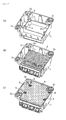
FIG. 2(a) to FIG. 2(c) show the essential parts of the occupant restraint device controller of the present invention in the assembling order,FIG. 2 (a) showing a state in which a ground lead-out member is mounted to the case,FIG. 2 (b) showing a state in which an electronic circuit substrate is mounted in addition to the stateFIG. 2(a), and FIG. 2(c) showing a state in which a cover is mounted in addition to the stateFIG. 2(b) ; and -
FIG. 3 (a) to FIG. 3(c) are diagrams for explaining the ground lead-out member,FIG. 3 (a) being a perspective view,FIG. 3 (b) being a longitudinal cross-sectional view of a portion where the ground lead-out member is mounted to a fixing leg, andFIG. 3(c) is a longitudinal cross-sectional view of a mounting portion to be mounted to the vehicle. -
- 1
- case
- 1a
- mounting portion
- 1b
- fixing leg
- 2
- electronic circuit substrate
- 3
- ground lead-out member
- 3a
- first spring structure
- 3b
- ground terminal
- 3c
- second spring structure
- 6
- vehicle
- The present invention achieved the object of providing grounding performance similar to that of the conventional counterpart even when a resin case is employed for weight reduction, by providing a structure to the case for leading out a ground electrode from inside to outside.
- Exemplary embodiments for carrying out the present invention will be hereinafter described using
FIG. 1 to FIG. 3 .
Reference numeral 1 denotes a resin case, which has a box-like shape with the top and one side wall open, and is provided withvehicle mounting portions 1a at three corners, for example, on the outer circumference of the top opening. In order that anelectronic component substrate 2 incorporating therein a control circuit for outputting a control signal to deploy an air bag, for example, can be accommodated, fixinglegs 1b for fixing theelectronic component substrate 2 are provided at four corners inside thiscase 1. -
Reference numeral 3 denotes a ground lead-out member for leading out a ground electrode from the inside of thecase 1 to the outside, which connects one of themounting portions 1a and one of thefixing legs 1b of the case 1 (seeFIG. 2(a) ). - This ground lead-out
member 3 is made up of afirst spring structure 3a that is the portion to be mounted to thefixing leg 1b, aground terminal 3b that is the portion to be mounted to thevehicle 6, and asecond spring structure 3c that connects thesefirst spring structure 3a andground terminal 3b. - Of these, the
first spring structure 3a has a configuration in which, for example as shown inFIG. 3(a) , part thereof is cut out with a slit, and a step is formed to this cut-out portion 3aa. The first spring structure is mounted such as to be held between thefixing leg 1b and theelectronic circuit substrate 2, as shown inFIG. 3(b) , with ascrew 4. In this way, this spring structure enables grounding strength of theelectronic circuit substrate 2 to be maintained even if thecase 1 reduces in size due to changes over time.Reference numeral 5 denotes a cover attached on top of theelectronic circuit substrate 2. - The
ground terminal 3b, on the other hand, does not employ such a structure as that of thefirst spring structure 3a. Therefore, as it is mounted with abolt 7 such as to be held between themounting portion 1a and part of thevehicle 6 as shown inFIG. 3 (c) , this mounting portion cannot absorb changes over time of thecase 1. - However, since the portion connecting the
first spring structure 3a and theground terminal 3b is formed in a bent shape to have a spring structure (second spring structure 3c), thissecond spring structure 3c enables grounding strength of theelectronic circuit substrate 2 to be maintained even if thecase 1 reduces in size due to changes over time. - Namely, according to the present invention, with the effect of the
first spring structure 3a and thesecond spring structure 3c of the ground lead-outmember 3, stabilization of the electronic equipment can be ensured even if theresin case 1 is employed in an attempt to reduce weight. - Described below is the results of a constant temperature humidity test (ambient temperature: 85°C, humidity: 85%, 1000 hours) carried out to prove that the above-described present invention exhibits electronic equipment stabilizing performance equivalent to that of conventional products that employ aluminum die cast cases.
- Table 1 below shows the contact resistance before the constant temperature humidity test, and Table 2 shows the contact resistance after the constant temperature humidity test, of the present invention products and conventional products. In the
invention product 1 in Tables 1 and 2, fixing was achieved with screws as shown in the accompanying drawings, while in theinvention product 2, attachment with the fixing legs was achieved by thermal bonding. Theconventional product 1 was grounded at four points, while theconventional product 2 was grounded at five points. -
[Table 1] Portion mounted to fixing leg Portion mounted to vehicle Invention product 1 0.010 0.017 Invention product 20.015 0.010 Conventional product 10.012 0.012 Conventional product 20.010 0.012 (unit: Ω) -
[Table 2] Portion mounted to fixing leg Portion mounted to vehicle Invention product 1 0.010 0.015 Invention product 20.003 0.015 Conventional product 10.010 0.060 Conventional product 20.001 1.850 (unit: Ω) - From Tables 1 and 2 above, it was proved that the resistance did not change much before and after the test in both of the
present invention products conventional products present invention products conventional products - The present invention is not restricted to the above-described example and the embodiment may be changed suitably as long as such changes are made within the scope of technical ideas described in the claims.
- Namely, the occupant restraint device controller described in the foregoing is a preferred example of the present invention, and other embodiments than the above can be worked out or carried out in various manners. Unless otherwise expressed herein to the contrary, the present invention should not be restricted to the shape, size, and configuration/layout and the like of particular components shown in the accompanying drawings. The expressions and terms used herein are for illustrative purposes only and not meant to be limiting unless otherwise expressed to the contrary.
- For example, attachment to the fixing
leg 1b is not restricted to by way ofscrews 4 as described with reference toFIG. 3 , but may be achieved by thermal bonding as with the invention product example 2. - The present invention described above is effective for any cases, not only of a device for controlling deployment of an airbag, but of a device for controlling restraint with a seatbelt or the like, as long as the case accommodates equipment that needs to be grounded.
Claims (1)
- An occupant restraint device controller, comprising:a sensor detecting acceleration or deceleration of a vehicle; andan electronic circuit substrate incorporating therein a control circuit that determines whether or not the vehicle has collided based on a detection output of this sensor and outputs a control signal for activating an occupant restraint tool,wherein the electronic circuit substrate is accommodated inside a resin case provided with a structure for leading out a ground electrode from inside to outside, andthe structure for leading out a ground electrode is configured such that a fixing leg for fixing the electronic circuit substrate is provided inside the case, this fixing leg being connected to a mounting portion to be mounted to the vehicle, via a ground lead-out member including a first spring structure held between the fixing leg and the electronic circuit substrate, a ground terminal held between the case and part of the vehicle, and a second spring structure in a bent shape connecting the first spring structure and the ground terminal.
Applications Claiming Priority (2)
| Application Number | Priority Date | Filing Date | Title |
|---|---|---|---|
| JP2009068497 | 2009-03-19 | ||
| PCT/JP2010/054435 WO2010107025A1 (en) | 2009-03-19 | 2010-03-16 | Occupant restraint device control device |
Publications (3)
| Publication Number | Publication Date |
|---|---|
| EP2409880A1 true EP2409880A1 (en) | 2012-01-25 |
| EP2409880A4 EP2409880A4 (en) | 2013-11-06 |
| EP2409880B1 EP2409880B1 (en) | 2015-08-19 |
Family
ID=42739685
Family Applications (1)
| Application Number | Title | Priority Date | Filing Date |
|---|---|---|---|
| EP10753517.1A Active EP2409880B1 (en) | 2009-03-19 | 2010-03-16 | Occupant restraint device control device |
Country Status (5)
| Country | Link |
|---|---|
| US (1) | US8532882B2 (en) |
| EP (1) | EP2409880B1 (en) |
| JP (1) | JP5425182B2 (en) |
| CN (1) | CN102356012B (en) |
| WO (1) | WO2010107025A1 (en) |
Cited By (1)
| Publication number | Priority date | Publication date | Assignee | Title |
|---|---|---|---|---|
| EP3376001A4 (en) * | 2015-11-12 | 2019-07-03 | Isuzu Motors Limited | GROUNDING STRUCTURE FOR INTERNAL COMBUSTION ENGINE |
Families Citing this family (10)
| Publication number | Priority date | Publication date | Assignee | Title |
|---|---|---|---|---|
| JP5270649B2 (en) * | 2010-12-09 | 2013-08-21 | オートリブ ディベロップメント エービー | Control device for occupant restraint system |
| WO2013011747A1 (en) * | 2011-07-21 | 2013-01-24 | オートリブ ディベロップメント エービー | Electronic circuit device for airbag deployment |
| US20130062137A1 (en) * | 2011-09-14 | 2013-03-14 | Hitachi Automotive Systems, Ltd. | Electric Power Steering System |
| CN204069593U (en) * | 2011-12-26 | 2014-12-31 | 奥托立夫开发公司 | Occupant restraint control device |
| CN202624132U (en) * | 2012-06-07 | 2012-12-26 | 奥托立夫开发公司 | Electronic control device for vehicle |
| JP6378714B2 (en) * | 2016-04-20 | 2018-08-22 | 矢崎総業株式会社 | Electrical junction box |
| US10167017B2 (en) | 2016-05-25 | 2019-01-01 | Takata Corporation | Steering wheel |
| JPWO2021044831A1 (en) * | 2019-09-02 | 2021-03-11 | ||
| CN115923709A (en) * | 2022-10-31 | 2023-04-07 | 江苏联成开拓集团有限公司 | Automobile safety air bag controller |
| WO2025196978A1 (en) * | 2024-03-19 | 2025-09-25 | 株式会社オートネットワーク技術研究所 | Electrical junction box |
Family Cites Families (17)
| Publication number | Priority date | Publication date | Assignee | Title |
|---|---|---|---|---|
| JPS6262746U (en) * | 1985-10-07 | 1987-04-18 | ||
| JPS6339870U (en) * | 1986-09-02 | 1988-03-15 | ||
| JPH09207706A (en) * | 1996-02-01 | 1997-08-12 | Hitachi Ltd | Collision detection device |
| JP3721242B2 (en) * | 1997-03-31 | 2005-11-30 | 日産自動車株式会社 | Control device for occupant restraint safety device |
| JP2000033848A (en) | 1998-07-17 | 2000-02-02 | Asuko Kk | Airbag control unit |
| JP2000292100A (en) * | 1999-04-09 | 2000-10-20 | Showa Kinzoku Kogyo Kk | Electric ignition type gas generator |
| DE29918914U1 (en) * | 1999-10-27 | 2000-03-09 | TRW Automotive Electronics & Components GmbH & Co. KG, 78315 Radolfzell | Control device for occupant restraint systems in vehicles |
| DE20012623U1 (en) * | 2000-07-18 | 2000-11-30 | TRW Automotive Electronics & Components GmbH & Co. KG, 78315 Radolfzell | Housing for an electronic control unit in vehicles |
| JP2003260992A (en) * | 2002-03-06 | 2003-09-16 | Denso Corp | Electrical circuit protection device |
| JP4016746B2 (en) * | 2002-07-05 | 2007-12-05 | 住友電装株式会社 | Manufacturing method of electronic control unit |
| JP3967642B2 (en) * | 2002-07-26 | 2007-08-29 | 株式会社ジェイテクト | Vehicle steering control system |
| JP2005064938A (en) | 2003-08-14 | 2005-03-10 | Nec Access Technica Ltd | Antenna for small radiotelephone |
| JP2005155827A (en) * | 2003-11-27 | 2005-06-16 | Fujitsu Ten Ltd | Fixing structure |
| DE10361647A1 (en) * | 2003-12-30 | 2005-08-04 | General Motors Corp., Detroit | Vehicle safety system for use in a vehicle with a fuel cell system and an electric power source where the fuel cell system is connected to the air bag control |
| JP2006319854A (en) | 2005-05-16 | 2006-11-24 | Matsushita Electric Ind Co Ltd | Portable terminal device and shield plate thereof |
| JP4686304B2 (en) * | 2005-08-25 | 2011-05-25 | 日信工業株式会社 | Electronic device and method for manufacturing electronic device |
| JP2007069828A (en) * | 2005-09-08 | 2007-03-22 | Toyoda Gosei Co Ltd | Display control device for information of gas pressure type actuator device of vehicle |
-
2010
- 2010-03-16 EP EP10753517.1A patent/EP2409880B1/en active Active
- 2010-03-16 JP JP2011504847A patent/JP5425182B2/en active Active
- 2010-03-16 US US13/257,422 patent/US8532882B2/en active Active
- 2010-03-16 CN CN201080012416.5A patent/CN102356012B/en active Active
- 2010-03-16 WO PCT/JP2010/054435 patent/WO2010107025A1/en not_active Ceased
Cited By (2)
| Publication number | Priority date | Publication date | Assignee | Title |
|---|---|---|---|---|
| EP3376001A4 (en) * | 2015-11-12 | 2019-07-03 | Isuzu Motors Limited | GROUNDING STRUCTURE FOR INTERNAL COMBUSTION ENGINE |
| US10415441B2 (en) | 2015-11-12 | 2019-09-17 | Isuzu Motors Limited | Grounding structure for internal combustion engine |
Also Published As
| Publication number | Publication date |
|---|---|
| JP5425182B2 (en) | 2014-02-26 |
| US20120010784A1 (en) | 2012-01-12 |
| CN102356012A (en) | 2012-02-15 |
| EP2409880A4 (en) | 2013-11-06 |
| JPWO2010107025A1 (en) | 2012-09-20 |
| EP2409880B1 (en) | 2015-08-19 |
| WO2010107025A1 (en) | 2010-09-23 |
| CN102356012B (en) | 2015-04-22 |
| US8532882B2 (en) | 2013-09-10 |
Similar Documents
| Publication | Publication Date | Title |
|---|---|---|
| EP2409880B1 (en) | Occupant restraint device control device | |
| US8096576B2 (en) | Housing fixing structure | |
| US8596674B2 (en) | Vehicle side airbag apparatus | |
| US7198288B2 (en) | Side air bag for a motor vehicle | |
| US7500394B2 (en) | Fastener integrated sensor | |
| JP2010215127A (en) | On-vehicle electronic device | |
| EP2541259A1 (en) | Sensors for detecting rapid deceleration/acceleration events | |
| US20080173107A1 (en) | Combination pressure and acceleration sensor | |
| CN100503315C (en) | Protective structures for circuit arrangements | |
| US6364144B1 (en) | Electric actuator casing comprising fall sensitive elements, especially one or more sensors intended for triggering protective device inside vehicles | |
| US7344153B1 (en) | Multiple sensor controlled vehicle airbag deployment system | |
| JP3193907U (en) | Occupant restraint device control device | |
| JPH0299440A (en) | Mounting construction for automotive electric equipment | |
| KR20090022399A (en) | Control panel fasteners. | |
| CN101535091B (en) | Crash Safety Control | |
| JP4462226B2 (en) | Vehicle sensor casing and vehicle sensor casing fixing structure | |
| JP2004239617A (en) | Sensor device | |
| WO2013042506A1 (en) | Control device for occupant restraint apparatus | |
| KR20210017080A (en) | Apparatus for object sensing and method for manufacturing the same | |
| KR20050075838A (en) | Air-bag pcb module | |
| HK1174975A (en) | Sensors for detecting rapid deceleration/acceleration events | |
| KR19990017854U (en) | Passenger car airbag system in case of collision with truck | |
| JPH05256867A (en) | Impact detecting device | |
| JPH05221282A (en) | Vehicle quick deceleration condition detecting device | |
| KR19980053037U (en) | Body Airbag |
Legal Events
| Date | Code | Title | Description |
|---|---|---|---|
| PUAI | Public reference made under article 153(3) epc to a published international application that has entered the european phase |
Free format text: ORIGINAL CODE: 0009012 |
|
| 17P | Request for examination filed |
Effective date: 20110903 |
|
| AK | Designated contracting states |
Kind code of ref document: A1 Designated state(s): AT BE BG CH CY CZ DE DK EE ES FI FR GB GR HR HU IE IS IT LI LT LU LV MC MK MT NL NO PL PT RO SE SI SK SM TR |
|
| DAX | Request for extension of the european patent (deleted) | ||
| A4 | Supplementary search report drawn up and despatched |
Effective date: 20131007 |
|
| RIC1 | Information provided on ipc code assigned before grant |
Ipc: B60R 16/02 20060101ALI20130930BHEP Ipc: H05K 9/00 20060101ALI20130930BHEP Ipc: B60R 21/00 20060101AFI20130930BHEP |
|
| 17Q | First examination report despatched |
Effective date: 20140416 |
|
| GRAP | Despatch of communication of intention to grant a patent |
Free format text: ORIGINAL CODE: EPIDOSNIGR1 |
|
| INTG | Intention to grant announced |
Effective date: 20150313 |
|
| GRAS | Grant fee paid |
Free format text: ORIGINAL CODE: EPIDOSNIGR3 |
|
| GRAA | (expected) grant |
Free format text: ORIGINAL CODE: 0009210 |
|
| AK | Designated contracting states |
Kind code of ref document: B1 Designated state(s): AT BE BG CH CY CZ DE DK EE ES FI FR GB GR HR HU IE IS IT LI LT LU LV MC MK MT NL NO PL PT RO SE SI SK SM TR |
|
| REG | Reference to a national code |
Ref country code: GB Ref legal event code: FG4D |
|
| REG | Reference to a national code |
Ref country code: CH Ref legal event code: EP |
|
| REG | Reference to a national code |
Ref country code: IE Ref legal event code: FG4D |
|
| REG | Reference to a national code |
Ref country code: AT Ref legal event code: REF Ref document number: 743563 Country of ref document: AT Kind code of ref document: T Effective date: 20150915 |
|
| REG | Reference to a national code |
Ref country code: DE Ref legal event code: R096 Ref document number: 602010026837 Country of ref document: DE |
|
| REG | Reference to a national code |
Ref country code: AT Ref legal event code: MK05 Ref document number: 743563 Country of ref document: AT Kind code of ref document: T Effective date: 20150819 |
|
| REG | Reference to a national code |
Ref country code: LT Ref legal event code: MG4D |
|
| REG | Reference to a national code |
Ref country code: NL Ref legal event code: MP Effective date: 20150819 |
|
| PG25 | Lapsed in a contracting state [announced via postgrant information from national office to epo] |
Ref country code: LT Free format text: LAPSE BECAUSE OF FAILURE TO SUBMIT A TRANSLATION OF THE DESCRIPTION OR TO PAY THE FEE WITHIN THE PRESCRIBED TIME-LIMIT Effective date: 20150819 Ref country code: FI Free format text: LAPSE BECAUSE OF FAILURE TO SUBMIT A TRANSLATION OF THE DESCRIPTION OR TO PAY THE FEE WITHIN THE PRESCRIBED TIME-LIMIT Effective date: 20150819 Ref country code: GR Free format text: LAPSE BECAUSE OF FAILURE TO SUBMIT A TRANSLATION OF THE DESCRIPTION OR TO PAY THE FEE WITHIN THE PRESCRIBED TIME-LIMIT Effective date: 20151120 Ref country code: NO Free format text: LAPSE BECAUSE OF FAILURE TO SUBMIT A TRANSLATION OF THE DESCRIPTION OR TO PAY THE FEE WITHIN THE PRESCRIBED TIME-LIMIT Effective date: 20151119 Ref country code: LV Free format text: LAPSE BECAUSE OF FAILURE TO SUBMIT A TRANSLATION OF THE DESCRIPTION OR TO PAY THE FEE WITHIN THE PRESCRIBED TIME-LIMIT Effective date: 20150819 |
|
| PG25 | Lapsed in a contracting state [announced via postgrant information from national office to epo] |
Ref country code: IS Free format text: LAPSE BECAUSE OF FAILURE TO SUBMIT A TRANSLATION OF THE DESCRIPTION OR TO PAY THE FEE WITHIN THE PRESCRIBED TIME-LIMIT Effective date: 20151219 Ref country code: PL Free format text: LAPSE BECAUSE OF FAILURE TO SUBMIT A TRANSLATION OF THE DESCRIPTION OR TO PAY THE FEE WITHIN THE PRESCRIBED TIME-LIMIT Effective date: 20150819 Ref country code: SE Free format text: LAPSE BECAUSE OF FAILURE TO SUBMIT A TRANSLATION OF THE DESCRIPTION OR TO PAY THE FEE WITHIN THE PRESCRIBED TIME-LIMIT Effective date: 20150819 Ref country code: PT Free format text: LAPSE BECAUSE OF FAILURE TO SUBMIT A TRANSLATION OF THE DESCRIPTION OR TO PAY THE FEE WITHIN THE PRESCRIBED TIME-LIMIT Effective date: 20151221 Ref country code: ES Free format text: LAPSE BECAUSE OF FAILURE TO SUBMIT A TRANSLATION OF THE DESCRIPTION OR TO PAY THE FEE WITHIN THE PRESCRIBED TIME-LIMIT Effective date: 20150819 Ref country code: AT Free format text: LAPSE BECAUSE OF FAILURE TO SUBMIT A TRANSLATION OF THE DESCRIPTION OR TO PAY THE FEE WITHIN THE PRESCRIBED TIME-LIMIT Effective date: 20150819 |
|
| REG | Reference to a national code |
Ref country code: FR Ref legal event code: PLFP Year of fee payment: 7 |
|
| PG25 | Lapsed in a contracting state [announced via postgrant information from national office to epo] |
Ref country code: NL Free format text: LAPSE BECAUSE OF FAILURE TO SUBMIT A TRANSLATION OF THE DESCRIPTION OR TO PAY THE FEE WITHIN THE PRESCRIBED TIME-LIMIT Effective date: 20150819 |
|
| PG25 | Lapsed in a contracting state [announced via postgrant information from national office to epo] |
Ref country code: SK Free format text: LAPSE BECAUSE OF FAILURE TO SUBMIT A TRANSLATION OF THE DESCRIPTION OR TO PAY THE FEE WITHIN THE PRESCRIBED TIME-LIMIT Effective date: 20150819 Ref country code: EE Free format text: LAPSE BECAUSE OF FAILURE TO SUBMIT A TRANSLATION OF THE DESCRIPTION OR TO PAY THE FEE WITHIN THE PRESCRIBED TIME-LIMIT Effective date: 20150819 Ref country code: CZ Free format text: LAPSE BECAUSE OF FAILURE TO SUBMIT A TRANSLATION OF THE DESCRIPTION OR TO PAY THE FEE WITHIN THE PRESCRIBED TIME-LIMIT Effective date: 20150819 Ref country code: IT Free format text: LAPSE BECAUSE OF FAILURE TO SUBMIT A TRANSLATION OF THE DESCRIPTION OR TO PAY THE FEE WITHIN THE PRESCRIBED TIME-LIMIT Effective date: 20150819 Ref country code: DK Free format text: LAPSE BECAUSE OF FAILURE TO SUBMIT A TRANSLATION OF THE DESCRIPTION OR TO PAY THE FEE WITHIN THE PRESCRIBED TIME-LIMIT Effective date: 20150819 |
|
| REG | Reference to a national code |
Ref country code: DE Ref legal event code: R097 Ref document number: 602010026837 Country of ref document: DE |
|
| PG25 | Lapsed in a contracting state [announced via postgrant information from national office to epo] |
Ref country code: RO Free format text: LAPSE BECAUSE OF FAILURE TO SUBMIT A TRANSLATION OF THE DESCRIPTION OR TO PAY THE FEE WITHIN THE PRESCRIBED TIME-LIMIT Effective date: 20150819 |
|
| PLBE | No opposition filed within time limit |
Free format text: ORIGINAL CODE: 0009261 |
|
| STAA | Information on the status of an ep patent application or granted ep patent |
Free format text: STATUS: NO OPPOSITION FILED WITHIN TIME LIMIT |
|
| 26N | No opposition filed |
Effective date: 20160520 |
|
| PG25 | Lapsed in a contracting state [announced via postgrant information from national office to epo] |
Ref country code: BE Free format text: LAPSE BECAUSE OF NON-PAYMENT OF DUE FEES Effective date: 20160331 Ref country code: SI Free format text: LAPSE BECAUSE OF FAILURE TO SUBMIT A TRANSLATION OF THE DESCRIPTION OR TO PAY THE FEE WITHIN THE PRESCRIBED TIME-LIMIT Effective date: 20150819 |
|
| PG25 | Lapsed in a contracting state [announced via postgrant information from national office to epo] |
Ref country code: LU Free format text: LAPSE BECAUSE OF FAILURE TO SUBMIT A TRANSLATION OF THE DESCRIPTION OR TO PAY THE FEE WITHIN THE PRESCRIBED TIME-LIMIT Effective date: 20160316 Ref country code: MC Free format text: LAPSE BECAUSE OF FAILURE TO SUBMIT A TRANSLATION OF THE DESCRIPTION OR TO PAY THE FEE WITHIN THE PRESCRIBED TIME-LIMIT Effective date: 20150819 |
|
| REG | Reference to a national code |
Ref country code: CH Ref legal event code: PL |
|
| REG | Reference to a national code |
Ref country code: IE Ref legal event code: MM4A |
|
| PG25 | Lapsed in a contracting state [announced via postgrant information from national office to epo] |
Ref country code: BE Free format text: LAPSE BECAUSE OF FAILURE TO SUBMIT A TRANSLATION OF THE DESCRIPTION OR TO PAY THE FEE WITHIN THE PRESCRIBED TIME-LIMIT Effective date: 20150819 |
|
| PG25 | Lapsed in a contracting state [announced via postgrant information from national office to epo] |
Ref country code: CH Free format text: LAPSE BECAUSE OF NON-PAYMENT OF DUE FEES Effective date: 20160331 Ref country code: IE Free format text: LAPSE BECAUSE OF NON-PAYMENT OF DUE FEES Effective date: 20160316 Ref country code: LI Free format text: LAPSE BECAUSE OF NON-PAYMENT OF DUE FEES Effective date: 20160331 |
|
| REG | Reference to a national code |
Ref country code: FR Ref legal event code: PLFP Year of fee payment: 8 |
|
| PG25 | Lapsed in a contracting state [announced via postgrant information from national office to epo] |
Ref country code: MT Free format text: LAPSE BECAUSE OF FAILURE TO SUBMIT A TRANSLATION OF THE DESCRIPTION OR TO PAY THE FEE WITHIN THE PRESCRIBED TIME-LIMIT Effective date: 20150819 |
|
| REG | Reference to a national code |
Ref country code: FR Ref legal event code: PLFP Year of fee payment: 9 |
|
| PGFP | Annual fee paid to national office [announced via postgrant information from national office to epo] |
Ref country code: GB Payment date: 20180328 Year of fee payment: 9 |
|
| PG25 | Lapsed in a contracting state [announced via postgrant information from national office to epo] |
Ref country code: HU Free format text: LAPSE BECAUSE OF FAILURE TO SUBMIT A TRANSLATION OF THE DESCRIPTION OR TO PAY THE FEE WITHIN THE PRESCRIBED TIME-LIMIT; INVALID AB INITIO Effective date: 20100316 Ref country code: SM Free format text: LAPSE BECAUSE OF FAILURE TO SUBMIT A TRANSLATION OF THE DESCRIPTION OR TO PAY THE FEE WITHIN THE PRESCRIBED TIME-LIMIT Effective date: 20150819 Ref country code: CY Free format text: LAPSE BECAUSE OF FAILURE TO SUBMIT A TRANSLATION OF THE DESCRIPTION OR TO PAY THE FEE WITHIN THE PRESCRIBED TIME-LIMIT Effective date: 20150819 |
|
| PG25 | Lapsed in a contracting state [announced via postgrant information from national office to epo] |
Ref country code: MT Free format text: LAPSE BECAUSE OF FAILURE TO SUBMIT A TRANSLATION OF THE DESCRIPTION OR TO PAY THE FEE WITHIN THE PRESCRIBED TIME-LIMIT Effective date: 20160331 Ref country code: HR Free format text: LAPSE BECAUSE OF FAILURE TO SUBMIT A TRANSLATION OF THE DESCRIPTION OR TO PAY THE FEE WITHIN THE PRESCRIBED TIME-LIMIT Effective date: 20150819 Ref country code: MK Free format text: LAPSE BECAUSE OF FAILURE TO SUBMIT A TRANSLATION OF THE DESCRIPTION OR TO PAY THE FEE WITHIN THE PRESCRIBED TIME-LIMIT Effective date: 20150819 Ref country code: TR Free format text: LAPSE BECAUSE OF FAILURE TO SUBMIT A TRANSLATION OF THE DESCRIPTION OR TO PAY THE FEE WITHIN THE PRESCRIBED TIME-LIMIT Effective date: 20150819 |
|
| REG | Reference to a national code |
Ref country code: DE Ref legal event code: R081 Ref document number: 602010026837 Country of ref document: DE Owner name: ARRIVER SOFTWARE AB, SE Free format text: FORMER OWNER: AUTOLIV DEVELOPMENT AB, VARGARDA, SE Ref country code: DE Ref legal event code: R081 Ref document number: 602010026837 Country of ref document: DE Owner name: VEONEER SWEDEN AB, SE Free format text: FORMER OWNER: AUTOLIV DEVELOPMENT AB, VARGARDA, SE |
|
| PG25 | Lapsed in a contracting state [announced via postgrant information from national office to epo] |
Ref country code: BG Free format text: LAPSE BECAUSE OF FAILURE TO SUBMIT A TRANSLATION OF THE DESCRIPTION OR TO PAY THE FEE WITHIN THE PRESCRIBED TIME-LIMIT Effective date: 20150819 |
|
| REG | Reference to a national code |
Ref country code: GB Ref legal event code: 732E Free format text: REGISTERED BETWEEN 20190808 AND 20190814 |
|
| GBPC | Gb: european patent ceased through non-payment of renewal fee |
Effective date: 20190316 |
|
| PG25 | Lapsed in a contracting state [announced via postgrant information from national office to epo] |
Ref country code: GB Free format text: LAPSE BECAUSE OF NON-PAYMENT OF DUE FEES Effective date: 20190316 |
|
| PGFP | Annual fee paid to national office [announced via postgrant information from national office to epo] |
Ref country code: FR Payment date: 20200324 Year of fee payment: 11 |
|
| PG25 | Lapsed in a contracting state [announced via postgrant information from national office to epo] |
Ref country code: FR Free format text: LAPSE BECAUSE OF NON-PAYMENT OF DUE FEES Effective date: 20210331 |
|
| REG | Reference to a national code |
Ref country code: DE Ref legal event code: R081 Ref document number: 602010026837 Country of ref document: DE Owner name: ARRIVER SOFTWARE AB, SE Free format text: FORMER OWNER: VEONEER SWEDEN AB, VARGARDA, SE Ref country code: DE Ref legal event code: R082 Ref document number: 602010026837 Country of ref document: DE Representative=s name: WAGNER & GEYER PARTNERSCHAFT MBB PATENT- UND R, DE Ref country code: DE Ref legal event code: R081 Ref document number: 602010026837 Country of ref document: DE Owner name: QUALCOMM AUTO LTD., CAMBRIDGE, GB Free format text: FORMER OWNER: VEONEER SWEDEN AB, VARGARDA, SE |
|
| REG | Reference to a national code |
Ref country code: DE Ref legal event code: R081 Ref document number: 602010026837 Country of ref document: DE Owner name: QUALCOMM AUTO LTD., CAMBRIDGE, GB Free format text: FORMER OWNER: ARRIVER SOFTWARE AB, LINKOEPING, SE |
|
| PGFP | Annual fee paid to national office [announced via postgrant information from national office to epo] |
Ref country code: DE Payment date: 20260213 Year of fee payment: 17 |