JP2004239617A - Sensor device - Google Patents
Sensor device Download PDFInfo
- Publication number
- JP2004239617A JP2004239617A JP2003025876A JP2003025876A JP2004239617A JP 2004239617 A JP2004239617 A JP 2004239617A JP 2003025876 A JP2003025876 A JP 2003025876A JP 2003025876 A JP2003025876 A JP 2003025876A JP 2004239617 A JP2004239617 A JP 2004239617A
- Authority
- JP
- Japan
- Prior art keywords
- sensor
- resin material
- sensor device
- vibration
- collision
- Prior art date
- Legal status (The legal status is an assumption and is not a legal conclusion. Google has not performed a legal analysis and makes no representation as to the accuracy of the status listed.)
- Granted
Links
Images


Abstract
Description
【0001】
【発明の属する技術分野】
本発明は、センシング部の物理的変位に応じて出力される電気信号によって衝突、振動、角速度等を検知可能な電子式センサを搭載したセンサ装置に関するものである。
【0002】
【従来の技術】
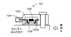
従来より、車両の衝突時にエアバッグの展開を行うために、衝突や振動を検知するための衝突検知センサ装置が車両前部等に搭載されている。そして、従来の衝突検知センサ装置では、例えば、図7に示す衝突検知センサ装置101のように、Gセンサ102を実装したP板(ガラスエポキシ系基板)109を、樹脂製の筐体103のGセンサ収容部103a内にて、筐体103に固定されたコネクタターミナル104にクリンチしてはんだ付けする構造や、図8に示す衝突検知センサ装置201のように、P板109を熱かしめすることにより筐体103へ固定する構造等が採用されている。また、Gセンサ102は、図示しないセンシング部の変形や移動等の物理的変位に応じて出力される電気信号によって衝突や振動を検出するように構成されており、構造体であるために必ず共振を発生させる周波数(共振点)が存在している。
【0003】
【発明が解決しようとする課題】
しかしながら、上述した従来構造の衝突検知センサ装置101又は201において、共振の原因となる高周波振動が、P板109によってある程度は減衰されるが、その減衰効果は、P板109の材質、サイズ、剛性、Gセンサ102を含めた重量、及びP板109を筐体103に固定する方法や固定位置によって異なってくる。そして、実際の製品設計においては、P板109の材質、サイズ、剛性、Gセンサ102を含めた重量は、回路規模によって決定され、P板109を筐体103に固定する方法や固定位置は、P板109のサイズによって決定されることになるため、このような構造から得られる高周波振動の減衰効果は成り行き任せとなっていたという問題があった。
【0004】
そして、P板109に実装されたGセンサ102のセンシング部(図示せず)の共振点が筐体103の共振点と重なる場合も想定され、そのような場合には、共振点を含む高周波振動の入力により、筐体103の共振にGセンサ102の共振が重畳し、Gセンサ102は入力Gよりも何倍も大きな検出値を出力することとなり、正しい衝突判定を行うことができない事態も生じうる。
【0005】
さらに、昨今の車両の衝突安全に関する法規やレーティング等に対応してエアバッグの車両搭載率が上昇しており、また、前突検知用だけでなく側突検知用の衝突検知センサ装置も搭載されるようになっている。これにより、車両1台当りの衝突検知センサ装置の搭載数も増加しており、センサ装置の製造コストを低減することの重要性が高まってきている。
【0006】
本発明は、上述した問題点に鑑みてなされたものであり、共振の原因となる高周波振動を確実に減衰させることが可能であり、且つ安価に製造可能なセンサ装置を提供することを解決すべき課題とする。
【0007】
【課題を解決するための手段】
この目的を達成するために、請求項1に記載のセンサ装置は、センシング部の物理的変位に応じて電気信号が出力される電子式センサと、その電子式センサが搭載される筐体とを備えたセンサ装置において、前記筐体は、高周波振動を減衰可能な第一の樹脂材料によって前記電子式センサの周囲を一次成形した一次成形部と、前記第一の樹脂材料よりも硬い第二の樹脂材料によって前記一次成形部の周囲を二次成形した二次成形部とからなることを特徴とする。
【0008】
従って、センシング部の物理的変位に応じて電気信号が出力される電子式センサは高周波帯域(例えば、周波数1kHz以上の帯域)に共振点を有するが、前記電子式センサの周囲が、高周波振動を減衰可能な第一の樹脂材料によって一次成形されているので、共振の原因となる高周波振動が確実に減衰し、センサ装置は、共振の影響を受けることなく、衝突、振動、角速度等の正しい検出出力を行うことができる。さらに、一次成形部の周囲が第一の樹脂材料よりも硬い第二の樹脂材料によって二次成形されているので、強度に優れており、センサ装置が車両前部のエンジンルーム内や側部のピラー内等のクラッシュゾーン(破壊領域)に配置された場合でも外部からの衝突によって筐体が破壊されることを防止することができる。また、一次成形及び二次成形が完了した時点でセンサ装置の組付けが完了し、従来必要であった電子式センサを筐体に組付ける後組付け工程が省略可能となり、製造工数の削減が可能であると共に、センサ装置を最小限必要な部品のみで構成することが可能となり、製造コストを大幅に低減することが可能となる。
【0009】
また、請求項2に記載のセンサ装置は、前記第一の樹脂材料が、液状シリコーンゴムであることを特徴とする。
【0010】
従って、電子式センサの周囲が、軟らかい樹脂材料である液状シリコーンゴムによって一次成形されているので、高周波振動を確実に減衰させることができる。
【0011】
【発明の実施の形態】
以下、本発明のセンサ装置を具体化した衝突検知センサ装置の一実施形態について図面を参照しつつ説明する。
【0012】
まず、本発明の実施形態の衝突検知センサ装置(以下、センサ装置と称する)1の構成について、図1を参照しつつ説明する。センサ装置1は、Gセンサ2と、筐体3とを主体として構成され、車両の前部等に搭載されて衝突を検知し、エアバッグ制御装置へ衝突検知信号を出力するためのセンサ装置である。
【0013】
Gセンサ2は、図示しないセンシング部(検知部)を備え、加速度(以下、単に”G”とも称する)が入力されると、センシング部に物理的変位(移動、変形等)が生じ、その変位量に応じた電気信号を出力するように構成されている。ここで、Gセンサ2は、全ての範囲の入力Gについて検出可能であることが理想的であるが、実際には、図2に示すように有限のダイナミックレンジ(検出可能な入力Gの範囲)を有しており、ダイナミックレンジを超える入力加速度が印加されると正しく検出することができない。また、Gセンサ2は、構造体であることから必ず共振点(共振周波数とも称する)を有している。よって、入力加速度の中にGセンサ2の共振点周波数成分が含まれていると、Gセンサ2の検知部は、Gセンサ2のダイナミックレンジを超える働きをすることがあり、この時、Gセンサ2は正しい検知ができなくなる。尚、Gセンサ2としては、例えば、センシング部の移動量によって加速度を検出するように構成された櫛歯式のGセンサ等を用いることができ、通信回路、電源回路等が1パッケージに集積化されている。
【0014】
筐体3は、樹脂材料によってGセンサ2を一体モールド成形したケース部分であり、Gセンサ2の周囲をなす一次成形部3aと、一次成形部3aの周囲に設けられて筐体3の外形をなす二次成形部3bとから構成されている。すなわち、センサ装置1は、まず、Gセンサ2と、Gセンサ2を外部に電気的接続するためのコネクタターミナル4と、車両取付け用のボルトが挿通される円筒状の金属ブッシュ6とを軟らかい樹脂材料(第一の樹脂材料)によって一体モールド成形(一次成形)することにより一次成形部3aを形成し、さらに、一次成形部3aの周囲を硬い樹脂材料(第二の樹脂材料)によって二次成形することによりセンサ装置1の外形を形成したものである。従って、従来のセンサ装置のように筐体を成形した後でGセンサを組付ける後組付け工程が省略されるので、製造工数の削減が可能であると共に、センサ装置1を最小限必要な部品のみで構成することが可能となり、従来よりも製造コストを大幅に低減することが可能となる。
【0015】
一次成形部3aをなす樹脂材料(第一の樹脂材料)としては、例えば、成形加工可能な軟らかい樹脂材料である液状シリコーンゴム等が好適に用いられる。従って、Gセンサ2の周囲が、高周波振動を減衰可能な第一の樹脂材料によって一次成形されているので、共振の原因となる高周波振動が確実に減衰し、センサ装置1は、共振の影響を受けることなく、衝突、振動の正しい検出出力を行うことができる。
【0016】
また、二次成形部3bをなす樹脂材料(第二の樹脂材料)としては、例えば、PBT(ポリブチレンテレフタレート)樹脂、ナイロン樹脂等の硬い樹脂材料が好適に用いられる。従って、一次成形部3aの周囲が第一の樹脂材料よりも硬い第二の樹脂材料によって二次成形されているので、強度に優れており、センサ装置1が、前突検知のために車両前部のエンジンルーム内に配置されたり、側突検知のために車両側部のピラー内やサイドシル部等のクラッシュゾーン(破壊領域)に配置された場合でも、外部からの衝突によって筐体3及びGセンサ2が破壊されることを防止することができる。
【0017】
コネクタターミナル4は、図示しない導体を介して図示しないエアバッグ制御装置に電気的に接続されており、Gセンサ2からの出力信号がエアバッグ制御装置に入力されるようになっている。エアバッグ制御装置は、Gセンサ2からの出力信号に基づいて、図示しないエアバッグの展開制御を行う。
【0018】
そして、センサ装置1は、筐体3の二次成形部3bにて一体モールド成形された金属ブッシュ6にボルトが挿通され、車両側取付け部に対して締付け固定される。
【0019】
次に、上述した構成を有するセンサ装置1において衝突を検知する場合の各部の作用について図面を参照しつつ説明する。
【0020】
車両の衝突等によってセンサ装置1に入力される振動は、あらゆる周波数成分により構成されている。この周波数成分は、図3に示すように、車両の衝突判定に必要な成分(主に低周波帯域、例えば周波数1kHz未満)と、衝突判定に不要な成分(主に高周波帯域、例えば周波数1kHz以上)とに二分することができる。また、Gセンサ2(より詳細には、センシング部)の共振点は、高周波帯域に属しており、筐体3の共振点はGセンサ2の共振点とは異なる周波数に設定されている(図3では、Gセンサ2の共振点よりも低く設定した例を示す)。尚、衝突判定に必要な周波数帯では、筐体の振動伝達の共振・減衰が無いことが必須条件であり、Gセンサの共振が始まる周波数以上では、Gセンサ2に入力されるる振動が、Gセンサ2の低周波数側の検知に影響ないレベルまで減衰していることが必須条件である。また、筐体の共振点はGセンサの共振点よりも低く設定されているため、筐体共振点付近の周波数帯では筐体の共振が生じても構わない。
【0021】
次に、衝突による衝突G振動入力からセンサ出力までの流れについて、図4乃至図6を参照しつつ説明する。衝突G振動は、図6(a)に示すように、低周波振動(太線で示す)に高周波振動(細線で示す)が重畳して構成されている。そして、車両を介してセンサ装置1に振動が伝達されると、図5に示すように、一次成形部3aの制振効果によって、Gセンサ2の共振点を含む高周波の振動が減衰され(共振ピークが低下し)、図6(b)に示すように、衝突判定に必要な低周波振動のみがGセンサ2に伝達される。そして、図6(c)に示すように、Gセンサ2にダイナミックレンジ内の低周波振動のみが伝達され、Gセンサ2から正しいG検出信号が出力される。これにより、エアバッグ制御装置では正しいG検出信号に基づいて正確に衝突状態を判定し、適切にエアバッグの展開制御を行うことができる。
【0022】
ここで、比較のため、従来のセンサ装置において振動伝達特性が不適当な場合を図6(d)に示す。図6(d)から明らかなように、高周波振動によりGセンサが共振し、特定周波数の振動が増幅されている。このため、Gセンサのダイナミックレンジを超えた振動が伝達されるため、正しいG検出信号を得ることができなかった。
【0023】
また、本実施形態によれば、Gセンサ2が、一次成形部3aをなす樹脂材料によって覆われることで気密性が保持され、湿気や腐食の原因を排除することができるという効果も奏される。
【0024】
尚、本発明は上述した実施形態に限定されるものではなく、本発明の主旨を逸脱しない範囲で種々の変更を施すことが可能である。
【0025】
例えば、前記実施形態では、本発明を加速度や振動を検出するための衝突検知センサ装置に適用した例を示したが、例えば、角速度を検出するためのロールオーバーセンサ、ロールレートセンサ、ヨーレートセンサ等に適用することも可能である。要するに、センシング部の物理的変位に応じて電気信号が出力される電子式センサと、その電子式センサが搭載される筐体とを備えたセンサ装置に本発明を適用することが可能である。
【0026】
また、一次成形部3a、二次成形部3bを形成する樹脂材料は上述した各材料には限られない。要するに、一次成形部3aを、高周波振動を減衰可能な第一の樹脂材料によって形成し、二次成形部3bを、第一の樹脂材料よりも硬い第二の樹脂材料によって形成すればよいのである。
【0027】
【発明の効果】
以上述べたように本発明のセンサ装置によれば、センシング部の物理的変位に応じて電気信号が出力される電子式センサが搭載される筐体において、電子式センサの周囲が、高周波振動を減衰可能な第一の樹脂材料によって一次成形されているので、共振の原因となる高周波振動が確実に減衰し、センサ装置は、共振の影響を受けることなく、衝突、振動、角速度等の正しい検出出力を行うことができる。さらに、一次成形部の周囲が第一の樹脂材料よりも硬い第二の樹脂材料によって二次成形されているので、強度に優れており、センサ装置が車両前部のエンジンルーム内や側部のピラー内等のクラッシュゾーン(破壊領域)に配置された場合でも外部からの衝突によって筐体が破壊されることを防止することができる。また、一次成形及び二次成形が完了した時点でセンサ装置の組付けが完了し、従来必要であった電子式センサを筐体に組付ける後組付け工程が省略可能となり、製造工数の削減が可能であると共に、センサ装置を最小限必要な部品のみで構成することが可能となり、製造コストを大幅に低減することが可能となる。
【図面の簡単な説明】
【図1】本発明の実施形態における衝突検知センサ装置を側方から視た状態を表す概略構成図である。
【図2】GセンサのG検出出力特性の一例を示すグラフである。
【図3】Gセンサ及び筐体における振動伝達率と振動周波数との関係を示すグラフである。
【図4】衝突G振動入力からセンサ出力までの流れを示す説明図である。
【図5】一次成形部の有無による筐体の振動伝達特性の変化を示すグラフである。
【図6】(a)は衝突Gの入力波形の一例を示すグラフを、(b)は一次成形部の制振効果によって高周波振動が減衰した振動波形の一例を示すグラフを、(c)はGセンサに入力される振動波形の一例を示すグラフを、(d)は従来のセンサ装置において振動伝達特性が不適当な場合のGセンサに伝達される振動波形の一例を示すグラフをそれぞれ示している。
【図7】従来技術における衝突検知センサ装置の一例を示す概略構成図である。
【図8】従来技術における衝突検知センサ装置の他の一例を示す概略構成図である。
【符号の説明】
1…衝突検知センサ装置(センサ装置)、2…Gセンサ(電子式センサ)、3…筐体、3a…一次成形部(第一の樹脂材料)、3b…二次成形部(第二の樹脂材料)。[0001]
TECHNICAL FIELD OF THE INVENTION
The present invention relates to a sensor device equipped with an electronic sensor capable of detecting a collision, a vibration, an angular velocity, and the like by an electric signal output according to a physical displacement of a sensing unit.
[0002]
[Prior art]
2. Description of the Related Art Conventionally, in order to deploy an airbag at the time of a vehicle collision, a collision detection sensor device for detecting a collision or vibration is mounted on a front portion of the vehicle or the like. In a conventional collision detection sensor device, for example, as in the collision
[0003]
[Problems to be solved by the invention]
However, in the above-described conventional structure of the collision
[0004]
It is also assumed that the resonance point of the sensing unit (not shown) of the
[0005]
In addition, the rate of mounting airbags on vehicles is increasing in response to recent regulations and ratings on vehicle collision safety, and a collision detection sensor device for side collision detection as well as front collision detection is installed. It has become so. As a result, the number of mounted collision detection sensor devices per vehicle is also increasing, and the importance of reducing the manufacturing cost of the sensor devices is increasing.
[0006]
The present invention has been made in view of the above-described problems, and has as its object to provide a sensor device that can reliably attenuate high-frequency vibrations that cause resonance and that can be manufactured at low cost. Should be a task to be done.
[0007]
[Means for Solving the Problems]
In order to achieve this object, a sensor device according to
[0008]
Therefore, an electronic sensor that outputs an electric signal according to the physical displacement of the sensing unit has a resonance point in a high frequency band (for example, a frequency band of 1 kHz or more). Since it is primarily molded with the first resin material that can be attenuated, high-frequency vibrations that cause resonance are reliably attenuated, and the sensor device can correctly detect collision, vibration, angular velocity, etc. without being affected by resonance. Output can be made. Furthermore, since the periphery of the primary molded portion is secondarily molded with the second resin material which is harder than the first resin material, the strength is excellent, and the sensor device is provided in the engine room at the front of the vehicle or at the side. Even when the housing is arranged in a crash zone (destruction area) such as in a pillar, it is possible to prevent the housing from being broken by an external collision. In addition, the assembly of the sensor device is completed when the primary molding and the secondary molding are completed, and the post-assembly step of assembling the electronic sensor to the housing, which was conventionally required, can be omitted, and the number of manufacturing steps can be reduced. In addition to being possible, the sensor device can be configured with only the minimum necessary components, and the manufacturing cost can be significantly reduced.
[0009]
The sensor device according to
[0010]
Therefore, since the periphery of the electronic sensor is primarily formed of liquid silicone rubber, which is a soft resin material, high-frequency vibration can be reliably attenuated.
[0011]
BEST MODE FOR CARRYING OUT THE INVENTION
Hereinafter, an embodiment of a collision detection sensor device embodying the sensor device of the present invention will be described with reference to the drawings.
[0012]
First, a configuration of a collision detection sensor device (hereinafter, referred to as a sensor device) 1 according to an embodiment of the present invention will be described with reference to FIG. The
[0013]
The
[0014]
The
[0015]
As the resin material (first resin material) forming the primary molded
[0016]
As the resin material (second resin material) forming the secondary molded
[0017]
The connector terminal 4 is electrically connected to an airbag control device (not shown) through a conductor (not shown), and an output signal from the
[0018]
Then, in the
[0019]
Next, the operation of each unit when a collision is detected in the
[0020]
The vibration input to the
[0021]
Next, the flow from the collision G vibration input due to the collision to the sensor output will be described with reference to FIGS. As shown in FIG. 6A, the collision G vibration is configured by superimposing a high-frequency vibration (shown by a thin line) on a low-frequency vibration (shown by a thick line). When vibration is transmitted to the
[0022]
Here, for comparison, FIG. 6D shows a case where the vibration transmission characteristic is inappropriate in the conventional sensor device. As is clear from FIG. 6D, the G sensor resonates due to the high frequency vibration, and the vibration of the specific frequency is amplified. For this reason, a vibration exceeding the dynamic range of the G sensor is transmitted, and a correct G detection signal cannot be obtained.
[0023]
Further, according to the present embodiment, the
[0024]
Note that the present invention is not limited to the above-described embodiment, and various changes can be made without departing from the gist of the present invention.
[0025]
For example, in the above-described embodiment, an example is shown in which the present invention is applied to a collision detection sensor device for detecting acceleration or vibration. For example, a rollover sensor, a roll rate sensor, a yaw rate sensor, and the like for detecting angular velocity It is also possible to apply to. In short, the present invention can be applied to a sensor device including an electronic sensor that outputs an electric signal in accordance with a physical displacement of the sensing unit, and a housing on which the electronic sensor is mounted.
[0026]
Further, the resin material forming the primary molded
[0027]
【The invention's effect】
As described above, according to the sensor device of the present invention, in a housing in which an electronic sensor that outputs an electric signal in accordance with the physical displacement of the sensing unit is mounted, the surroundings of the electronic sensor generate high-frequency vibrations. Since it is primarily molded with the first resin material that can be attenuated, high-frequency vibrations that cause resonance are reliably attenuated, and the sensor device can correctly detect collision, vibration, angular velocity, etc. without being affected by resonance. Output can be made. Furthermore, since the periphery of the primary molded portion is secondarily molded with the second resin material which is harder than the first resin material, the strength is excellent, and the sensor device is provided in the engine room at the front of the vehicle or at the side. Even when the housing is arranged in a crash zone (destruction area) such as in a pillar, it is possible to prevent the housing from being broken by an external collision. In addition, the assembly of the sensor device is completed when the primary molding and the secondary molding are completed, and the post-assembly step of assembling the electronic sensor to the housing, which was conventionally required, can be omitted, and the number of manufacturing steps can be reduced. In addition to being possible, the sensor device can be configured with only the minimum necessary components, and the manufacturing cost can be significantly reduced.
[Brief description of the drawings]
FIG. 1 is a schematic configuration diagram illustrating a state in which a collision detection sensor device according to an embodiment of the present invention is viewed from a side.
FIG. 2 is a graph showing an example of a G detection output characteristic of a G sensor.
FIG. 3 is a graph showing a relationship between a vibration transmission rate and a vibration frequency in a G sensor and a housing.
FIG. 4 is an explanatory diagram showing a flow from a collision G vibration input to a sensor output.
FIG. 5 is a graph showing a change in vibration transmission characteristics of a housing depending on the presence or absence of a primary molded portion.
6A is a graph illustrating an example of an input waveform of a collision G, FIG. 6B is a graph illustrating an example of a vibration waveform in which high-frequency vibration is attenuated by a vibration damping effect of a primary forming unit, and FIG. FIG. 4D is a graph illustrating an example of a vibration waveform input to the G sensor, and FIG. 5D is a graph illustrating an example of a vibration waveform transmitted to the G sensor when vibration transmission characteristics are inappropriate in a conventional sensor device. I have.
FIG. 7 is a schematic configuration diagram illustrating an example of a collision detection sensor device according to the related art.
FIG. 8 is a schematic configuration diagram showing another example of the collision detection sensor device according to the related art.
[Explanation of symbols]
DESCRIPTION OF
Claims (2)
前記筐体は、高周波振動を減衰可能な第一の樹脂材料によって前記電子式センサの周囲を一次成形した一次成形部と、前記第一の樹脂材料よりも硬い第二の樹脂材料によって前記一次成形部の周囲を二次成形した二次成形部とからなることを特徴とするセンサ装置。In a sensor device including an electronic sensor that outputs an electric signal according to a physical displacement of the sensing unit and a housing on which the electronic sensor is mounted,
The casing has a primary molded portion in which the periphery of the electronic sensor is primarily molded with a first resin material capable of attenuating high-frequency vibrations, and the primary molded portion is formed with a second resin material harder than the first resin material. A sensor device, comprising: a secondary molded portion in which the periphery of the portion is secondary molded.
Priority Applications (5)
| Application Number | Priority Date | Filing Date | Title |
|---|---|---|---|
| JP2003025876A JP4421824B2 (en) | 2003-02-03 | 2003-02-03 | Sensor device |
| EP06017060A EP1720018A3 (en) | 2003-02-03 | 2004-01-27 | Ceramic package for mounting electronic components |
| EP04001671A EP1443331A3 (en) | 2003-02-03 | 2004-01-27 | Sensor device and ceramic package for mounting electronic components |
| US10/765,882 US7116215B2 (en) | 2003-02-03 | 2004-01-29 | Sensor device and ceramic package for mounting electronic components |
| CN200410007431.7A CN1287130C (en) | 2003-02-03 | 2004-02-03 | Sensor device and ceramic encapsulated outer hull for electronic component |
Applications Claiming Priority (1)
| Application Number | Priority Date | Filing Date | Title |
|---|---|---|---|
| JP2003025876A JP4421824B2 (en) | 2003-02-03 | 2003-02-03 | Sensor device |
Publications (2)
| Publication Number | Publication Date |
|---|---|
| JP2004239617A true JP2004239617A (en) | 2004-08-26 |
| JP4421824B2 JP4421824B2 (en) | 2010-02-24 |
Family
ID=32954043
Family Applications (1)
| Application Number | Title | Priority Date | Filing Date |
|---|---|---|---|
| JP2003025876A Expired - Fee Related JP4421824B2 (en) | 2003-02-03 | 2003-02-03 | Sensor device |
Country Status (1)
| Country | Link |
|---|---|
| JP (1) | JP4421824B2 (en) |
Cited By (4)
| Publication number | Priority date | Publication date | Assignee | Title |
|---|---|---|---|---|
| JP2010071724A (en) * | 2008-09-17 | 2010-04-02 | Mitsubishi Electric Corp | Resin molded semiconductor sensor and method of manufacturing the same |
| JP2010071723A (en) * | 2008-09-17 | 2010-04-02 | Mitsubishi Electric Corp | Resin mold semiconductor sensor and method of manufacturing the same |
| JP2011529420A (en) * | 2008-07-28 | 2011-12-08 | ティーアールダブリュー・オートモーティブ・ユーエス・エルエルシー | Method and apparatus for housing a vehicle collision sensor |
| JP2012531351A (en) * | 2009-06-26 | 2012-12-10 | オートリブ エー・エス・ピー・インク | Improved electronic assembly |
-
2003
- 2003-02-03 JP JP2003025876A patent/JP4421824B2/en not_active Expired - Fee Related
Cited By (4)
| Publication number | Priority date | Publication date | Assignee | Title |
|---|---|---|---|---|
| JP2011529420A (en) * | 2008-07-28 | 2011-12-08 | ティーアールダブリュー・オートモーティブ・ユーエス・エルエルシー | Method and apparatus for housing a vehicle collision sensor |
| JP2010071724A (en) * | 2008-09-17 | 2010-04-02 | Mitsubishi Electric Corp | Resin molded semiconductor sensor and method of manufacturing the same |
| JP2010071723A (en) * | 2008-09-17 | 2010-04-02 | Mitsubishi Electric Corp | Resin mold semiconductor sensor and method of manufacturing the same |
| JP2012531351A (en) * | 2009-06-26 | 2012-12-10 | オートリブ エー・エス・ピー・インク | Improved electronic assembly |
Also Published As
| Publication number | Publication date |
|---|---|
| JP4421824B2 (en) | 2010-02-24 |
Similar Documents
| Publication | Publication Date | Title |
|---|---|---|
| JP3944052B2 (en) | Ultrasonic transducer and ultrasonic clearance sonar using the same | |
| JP4852940B2 (en) | Collision detection system | |
| US8414013B2 (en) | Housing structure for in-vehicle electronic device | |
| JP5184286B2 (en) | Housing fixing structure | |
| US7721603B2 (en) | Inertial sensor arrangement | |
| JP5685187B2 (en) | Method and apparatus for housing a vehicle collision sensor | |
| JP2007127537A (en) | Collision detection system for vehicle | |
| US6308554B1 (en) | Electronic device having an acceleration-sensitive sensor | |
| US8738223B2 (en) | Electronic control device | |
| US5706181A (en) | Sensor unit for controlling an occupant protection system of a motor vehicle | |
| JP3370682B2 (en) | Airbag control device | |
| JP2009504500A (en) | Fastener integrated sensor | |
| US7856880B2 (en) | Vehicle sensor for detecting impact sound | |
| JP4479629B2 (en) | Collision detection system | |
| US7624636B2 (en) | Method and system for operating a sensor | |
| JP2010215127A (en) | On-vehicle electronic device | |
| JP4421824B2 (en) | Sensor device | |
| US7267003B2 (en) | Acceleration sensor unit | |
| JP3201242B2 (en) | Sensor assembly and method of assembling the same | |
| JP2004294419A (en) | Sensor device | |
| KR20080010401A (en) | Torque sensor with inverted sensing element and integral shaft housing | |
| JP2005529785A (en) | Restraint system | |
| JP2004239616A (en) | Sensor device | |
| JP4222196B2 (en) | Electrical circuit equipment destruction prevention structure | |
| JP2004239618A (en) | Sensor device |
Legal Events
| Date | Code | Title | Description |
|---|---|---|---|
| A621 | Written request for application examination |
Free format text: JAPANESE INTERMEDIATE CODE: A621 Effective date: 20050511 |
|
| A977 | Report on retrieval |
Free format text: JAPANESE INTERMEDIATE CODE: A971007 Effective date: 20070427 |
|
| A131 | Notification of reasons for refusal |
Free format text: JAPANESE INTERMEDIATE CODE: A131 Effective date: 20070507 |
|
| A521 | Written amendment |
Free format text: JAPANESE INTERMEDIATE CODE: A523 Effective date: 20070629 |
|
| A02 | Decision of refusal |
Free format text: JAPANESE INTERMEDIATE CODE: A02 Effective date: 20070724 |
|
| A521 | Written amendment |
Free format text: JAPANESE INTERMEDIATE CODE: A523 Effective date: 20070918 |
|
| A911 | Transfer of reconsideration by examiner before appeal (zenchi) |
Free format text: JAPANESE INTERMEDIATE CODE: A911 Effective date: 20070928 |
|
| A912 | Removal of reconsideration by examiner before appeal (zenchi) |
Free format text: JAPANESE INTERMEDIATE CODE: A912 Effective date: 20071019 |
|
| A01 | Written decision to grant a patent or to grant a registration (utility model) |
Free format text: JAPANESE INTERMEDIATE CODE: A01 |
|
| A61 | First payment of annual fees (during grant procedure) |
Free format text: JAPANESE INTERMEDIATE CODE: A61 Effective date: 20091203 |
|
| FPAY | Renewal fee payment (event date is renewal date of database) |
Free format text: PAYMENT UNTIL: 20121211 Year of fee payment: 3 |
|
| R150 | Certificate of patent or registration of utility model |
Ref document number: 4421824 Country of ref document: JP Free format text: JAPANESE INTERMEDIATE CODE: R150 Free format text: JAPANESE INTERMEDIATE CODE: R150 |
|
| FPAY | Renewal fee payment (event date is renewal date of database) |
Free format text: PAYMENT UNTIL: 20131211 Year of fee payment: 4 |
|
| R250 | Receipt of annual fees |
Free format text: JAPANESE INTERMEDIATE CODE: R250 |
|
| R250 | Receipt of annual fees |
Free format text: JAPANESE INTERMEDIATE CODE: R250 |
|
| R250 | Receipt of annual fees |
Free format text: JAPANESE INTERMEDIATE CODE: R250 |
|
| R250 | Receipt of annual fees |
Free format text: JAPANESE INTERMEDIATE CODE: R250 |
|
| R250 | Receipt of annual fees |
Free format text: JAPANESE INTERMEDIATE CODE: R250 |
|
| LAPS | Cancellation because of no payment of annual fees |