EP2409810B1 - Method for fitting a door to a vehicle - Google Patents
Method for fitting a door to a vehicle Download PDFInfo
- Publication number
- EP2409810B1 EP2409810B1 EP20110005860 EP11005860A EP2409810B1 EP 2409810 B1 EP2409810 B1 EP 2409810B1 EP 20110005860 EP20110005860 EP 20110005860 EP 11005860 A EP11005860 A EP 11005860A EP 2409810 B1 EP2409810 B1 EP 2409810B1
- Authority
- EP
- European Patent Office
- Prior art keywords
- door
- bodywork
- vehicle
- auxiliary device
- side hinge
- Prior art date
- Legal status (The legal status is an assumption and is not a legal conclusion. Google has not performed a legal analysis and makes no representation as to the accuracy of the status listed.)
- Active
Links
- 238000000034 method Methods 0.000 title claims description 28
- 238000001514 detection method Methods 0.000 claims description 7
- 238000011156 evaluation Methods 0.000 claims description 6
- 238000012937 correction Methods 0.000 claims description 2
- 238000009434 installation Methods 0.000 description 5
- 238000004519 manufacturing process Methods 0.000 description 5
- 210000000746 body region Anatomy 0.000 description 2
- 230000002411 adverse Effects 0.000 description 1
- 230000000712 assembly Effects 0.000 description 1
- 238000000429 assembly Methods 0.000 description 1
- 230000001419 dependent effect Effects 0.000 description 1
- 230000002349 favourable effect Effects 0.000 description 1
- 238000005259 measurement Methods 0.000 description 1
- 238000012545 processing Methods 0.000 description 1
- 230000002787 reinforcement Effects 0.000 description 1
- 238000007665 sagging Methods 0.000 description 1
- 239000000523 sample Substances 0.000 description 1
- 238000000926 separation method Methods 0.000 description 1
- 239000000725 suspension Substances 0.000 description 1
Images


Classifications
-
- B—PERFORMING OPERATIONS; TRANSPORTING
- B62—LAND VEHICLES FOR TRAVELLING OTHERWISE THAN ON RAILS
- B62D—MOTOR VEHICLES; TRAILERS
- B62D65/00—Designing, manufacturing, e.g. assembling, facilitating disassembly, or structurally modifying motor vehicles or trailers, not otherwise provided for
- B62D65/02—Joining sub-units or components to, or positioning sub-units or components with respect to, body shell or other sub-units or components
- B62D65/06—Joining sub-units or components to, or positioning sub-units or components with respect to, body shell or other sub-units or components the sub-units or components being doors, windows, openable roofs, lids, bonnets, or weather strips or seals therefor
Definitions
- the invention relates to a method for mounting a door on a vehicle according to the preamble of claim 1.
- the mounting of the doors to a vehicle is of essential importance, since this is a union of two assemblies (door and vehicle body), which may be subject to strong tolerance variations, so that it is in improper installation of a door to a vehicle body may come to undesirably uneven gaps and alignment with respect to, for example, door edge area to the vehicle body. This is often only tedious and expensive to readjust the door hinges.
- a method for installing doors in a motor vehicle is known in which the door is held by hinges which comprise two mutually pivotable hinge halves and are fixed to the door or to the body that after installation of the door only the door-side Attachment points are accessible when the door is open.
- the hinges consisting of the two hinge halves are first attached to the body or to the door then the free hinge halves of the hinges are measured, and that in the measurement determined position data of the hinge halves are used to position the subsequent installation of the door hinge mounting surfaces on the door with respect to the free door-side hinge halves or to the free body-side hinge halves on the door relative to hinge attachment surfaces on the body.
- the at least one body-side hinge part is received by a first auxiliary device on a hinge axis part region forming the hinge axis, in particular on a bolt receptacle, and then positioned by means of the first auxiliary device in a positionally and positionally aligned manner on the vehicle body and then subsequently fixed.
- the door-side hinge parts by means of the further, second auxiliary device on a hinge axis forming the second hinge axis portion, in particular on an axle of the door-side hinge parts, received and then positioned by means of the second auxiliary device position and position accurately aligned on the door and further determined subsequently. Finally, the door is hung after the determination of all hinge parts without further alignment on the or the respectively associated body-side hinge part (s).
- the two hinge parts to be joined together are accurately recorded on the hinge axis and thus on the component separation, resulting in always constant and reproducible assembly and for the hinge part joints Cultivation conditions on the vehicle body and on the door result, which leads to the fact that production-related tolerances or inaccuracies of the hinge parts can not adversely affect the door assembly and thus the gap between the door and body.
- the solution according to the invention can thus achieve a significant quality improvement in the assembly of a door to a vehicle body, and that combined with fewer set times.
- the hinge tolerances are very well compensated by the split hinge structure with the recording positioning of the respective hinge parts on the hinge axes on the basis of the vehicle coordinate system, so that the manufacturing variations of the components can be compensated very well.
- the two hinge parts (or the door on the vehicle body) after the inventive positioning of the door-side and the hinge-side hinge parts need only be connected to each other without any further elaborate alignment.
- a complex device for final assembly of the vehicle door on the body, which allows alignment of the door to the body, can thus be advantageously saved and replaced by a simple device. As a result, a simple fully automated production can be realized in a simple manner.
- the auxiliary device accommodating the body-side and / or door-side hinge parts, in particular at the beginning of positioning of the auxiliary device is aligned and / or positioned only at a main reference point, which main reference point is formed, for example, by a body-side recess the a pin-like extension of the auxiliary device positively engages, but what the presence of more, eg Obviously, auxiliary reference points formed by distinctive component points or regions do not exclude.
- a substantially identical, exact positioning of hinge parts on the vehicle body or on the door can take place.
- the elements holding the hinge parts are preferably adjustable on the auxiliary device so that the hinge parts can always be arranged in the desired manner on the vehicle body or on the door.
- main reference point is understood to mean a reference point which always has to be present in an obligatory manner and / or which produces a first interlocking engagement of two components, thus e.g. a Hilfsvoriquess Schoer spinous process, which engages in a body or door-side recess.
- An auxiliary reference point is understood to mean a marked component region which can be determined as desired depending on the position and orientation of the main reference point, depending on the component geometry or contour, on which the component, in particular after the engagement connection produced at the main reference point, continues is aligned, eg a parapet, a window or a window sill, to name but a few examples.
- Body side has a plurality of, in particular two door openings, each of which a body-side door pillar area is assigned as the connection area for each door to be provided body-side hinge parts, wherein by means of the first auxiliary device substantially simultaneous positioning of the body-side hinge parts takes place at the, the plurality of door openings associated body-side door pillar areas or . is made.
- Particularly preferred here is an alignment and / or positioning of the first auxiliary device only at a main reference point of the door cutouts, which of course does not preclude the presence of further auxiliary reference points, as already shown above.
- two body-side hinge parts per body-side door pillar region can be provided in each case, so that by means of the auxiliary device a total of four body-side hinge parts are positioned substantially simultaneously on the vehicle body.
- the auxiliary device in addition to a stable connection of a vehicle door results in such a plurality of hinge parts the particular advantage that all hinges at the same time with little effort and therefore little time consuming can be positioned on the vehicle body in a single step, with particularly advantageous only one orientation of the auxiliary device to a Main reference point of one of the door openings is sufficient.
- the body-side hinge parts are positioned by means of the first auxiliary device on the vehicle body in two vehicle coordinate directions positional and positionally aligned, wherein the orientation in the third vehicle coordinate direction is effected by the abutment connection of the body-side hinge parts on the vehicle body.
- the body-side hinge parts on the vehicle body set in particular screwed by means of at least one screw.
- the auxiliary device is then moved away from the vehicle body.
- the body-side hinge parts on the vehicle body in the vehicle longitudinal direction (X-direction) and in the vehicle vertical axis direction (Z-direction) are aligned and positioned accurately positioned and.
- the alignment in the vehicle transverse direction (Y-direction) is effected by the system connection of the body-side hinge parts on the vehicle body.
- the door-side hinge parts can be positioned by means of the second auxiliary device at the respectively associated door in two vehicle coordinate directions position and position aligned, wherein the orientation in the third vehicle coordinate direction is effected by the abutment connection of the door-side hinge parts on the door.
- the auxiliary device is then moved away from the door here.
- the door-side hinge parts by means of further auxiliary device in the vehicle transverse direction (Y-direction) and in vehicle vertical axis direction (Z-direction) are aligned positionally and accurately, the alignment in the vehicle longitudinal direction (X-direction) then by the abutment connection of the door-side hinge parts the door is carried out, preferably on a vehicle transverse direction (Y-direction) extending door wall or door outer skin area.
- the door is positioned in a holding device before the positioning of the door-side hinge parts and held there by means of a reference point system and / or by means of a sensor device in defined vehicle coordinate directions (X, Y, Z direction) becomes.
- auxiliary devices are preferably used, the individual elements are adjustable so that always an optimal position of the hinge parts on the door and thus also to the body-side hinge part is ensured.
- a detection device in particular a camera device is arranged, by means of in a defined mounting home position moving auxiliary device, wherein the auxiliary device is at a defined distance to the vehicle body or the door, the current position of a body-side or door-side main reference point with respect to a device to be brought with the auxiliary device side reference point counter element as Ist Position value is detected and compared by means of an evaluation with a predetermined target position value.
- the position of the respective auxiliary device is such that the main reference point, for example a recess, and the reference point counterelement associated therewith, for example a spinous process which can be brought into the recess in a form-fitting manner, lie in alignment.
- the main reference point and reference point counter-element are brought into engagement with each other in a further assembly step, and thus the body-side or door-side hinge parts positioned on the vehicle body or the door.
- a fully automated attachment of the body-side and / or door-side hinge parts on the vehicle body or on the door can be achieved since the pre-positioning and alignment of the auxiliary device as well as the final positioning of the auxiliary device to the vehicle body the detection device, such as a camera with image analysis software, automatically takes place.
- the detection device such as a camera with image analysis software
- a further detection device in particular a camera device with image analysis software, is arranged on the body-side hinge parts positioning first auxiliary device, by means of the, in mutually engaging main reference point and reference point counter element, the position the first auxiliary device in the vehicle vertical axis direction (z-direction) with respect to a body region spaced from the main reference point, eg a window sill of the vehicle body, detected as a bias actual value and is compared by means of an evaluation with a predetermined bias value, the first auxiliary device is pivoted at a detected deviation to the pivot axis formed by the main reference point until the bias actual value Bias setpoint corresponds.
- the body-side hinge parts are fixed to the vehicle body.
- the bagging of the vehicle door hinged to the vehicle body due to its own weight ensures that each door can be mounted with an exact gap on the vehicle body.
- the invention also claims a device for carrying out a method according to one of the method claims of the invention.
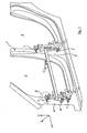
- Fig. 1 1 schematically shows one side of a vehicle body 1 (not shown here in full), which body side has two door openings 2, 3 at whose door openings 4, 5 are assigned to the respective door cut-outs 2, 3 by means of an auxiliary device 6, which is shown here only schematically and by way of example.
- an auxiliary device 6 which is shown here only schematically and by way of example.
- each two in the vehicle vertical axis direction z spaced body-side hinge parts 7 are positioned.
- left body side door pillar area 4 part of an A-pillar and in the image plane of the Fig. 2
- right body side door pillar area 5 part of a B pillar of the vehicle body.
- FIG. 4 An enlarged view of the configuration of the body-side hinge parts 7 is in the Fig. 4 shown.
- the positioning of the body-side hinge parts 7 by means of the auxiliary device 6 is preferably carried out using a reference point system (RPS).
- RPS reference point system
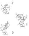
- the positionally accurate positioning and alignment of the body-side hinge parts 7 using the reference point system is carried out such that a formed on the body-side hinge part 7 bolt receptacle 10 of the auxiliary device 6, as shown in the Fig. 3a is shown only very schematically and by way of example, is or is, for example, such that a mandrel 11 engages in the bolt receptacle 10 and is passed therethrough.
- the auxiliary device 6 can be adjusted in the region of the mandrel 11 or the bolt receptacle 10 so that the bolt receptacle 10 and thus the body-side hinge part 7 both in the vehicle longitudinal direction (x-direction) and in the vehicle vertical axis direction (z-direction) exactly in a predetermined are aligned in a defined manner.
- the alignment in the vehicle transverse direction (y-direction) takes place in the present case by the system connection of the body-side hinge parts 7 on the respective body-side door pillar region 4 and 5 and thus to the vehicle body. 1
- auxiliary device 6 After the accurate positional positioning of the body-side hinge parts 7 on the vehicle body 1 thus carried out by means of the auxiliary device 6, these can be fixed to the vehicle body 1 by means of screw connections not shown in detail here. Subsequently, the auxiliary device 6 is then moved away from the vehicle body 1, so that in the Fig. 2 shown exact, positionally accurate arrangement of all body-side hinge parts 7 at a plurality of door cutouts having body side of a vehicle body 1 results.
- the body-side hinge parts 7 can be positioned on the opposite side of the vehicle.
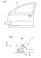
- the body-side hinge parts 7 associated door-side hinge parts 12 one of which by way of example in an enlarged detail in the Fig. 5 is shown at the in the Fig. 7 and in the Fig. 8 schematically illustrated body door or door 13 aligned precisely aligned preferably be positioned by means of a reference point system.
- the door-side hinge parts 12 by means of an auxiliary device not shown here on a pivot pin 14, for example by means of a in the Fig. 3b only extremely schematically illustrated, jaws 21a, 21b having jaw device 21 or the like, and in the three axial directions x, y and z of the vehicle coordinate system, preferably using a reference point system at a here substantially in the vehicle transverse direction (y-direction) extending door outer skin region 15 positioned.
- the device not shown here engages again in an analogous manner to the auxiliary device 6, for example, in a recess-like reference point on the door 13 and the outer door skin area 15 on or.
- the door-side hinge parts 12 After this successful positioning of the door-side hinge parts 12 receiving auxiliary device, the door-side hinge parts 12 in the vehicle transverse direction (y-direction) and in vehicle vertical axis direction (z-direction) by means of the auxiliary device position and position aligned, while again the orientation in the vehicle longitudinal direction (x Direction) by the abutment connection of the door-side hinge parts 12 on the door outer skin portion 15 of the door 13 takes place.
- This can be analogous to the one previously described in Connection with the Fig. 1 to 3 described manner, ie using a main reference point and a striking auxiliary reference point.
- the door 13 which has been preassembled in this way, is then simply hung by means of its axle bolts 14 in the body-side hinge parts 7 of the respectively assigned door cutout 2 or 3, without further alignment need.
- This connection is schematic in the Fig. 6 shown, in which the hinge axis 17 is located.
- a first camera device 18 may be arranged at the respective auxiliary device, here by way of example and preferably the auxiliary device 6, arranged.
- this camera device 18 With the auxiliary device 6 moved to a defined assembly starting position, in which the auxiliary device 6 is at a defined distance from the vehicle body 1, the current position of the body-side main reference point 9 can be engaged with it to be brought auxiliary device side spinous process 8 detected as the actual position value and compared by means of an evaluation device 19 with a predetermined desired position value.
- a position correction of the first auxiliary device 6 is automated in such a way that the main reference point 9 and the spinous process associated therewith 8 seen as a reference point counter element in the vehicle transverse direction (y-direction) are in alignment. With aligned main reference point 9 and spinous process 8, these are preferably brought automated in another assembly step with each other.
- a further camera device 20 may be arranged by means of which befindlichem with each other main reference point 9 and reference point counter element, the position of the auxiliary device 6 in the vehicle vertical axis direction (z-direction ) with respect to a spaced from the main reference point body area (auxiliary reference point) detected as a bias actual value and compared by means of an evaluation with a predetermined bias setpoint, the auxiliary device 6 at a detected deviation about the pivot axis formed by the main reference point 9 as long as pivoted until the bias value actual value corresponds to the bias setpoint.
- the body-side hinge parts 7 are then fixed to the vehicle body 1. This ensures that the door 13 is spaced after their suspension and after their self-weight-induced sagging with exactly the desired gap or nominal dimension to the vehicle body 1.
Description
Die Erfindung betrifft ein Verfahren zur Montage einer Tür an einem Fahrzeug nach dem Oberbegriff des Anspruchs 1.The invention relates to a method for mounting a door on a vehicle according to the preamble of claim 1.
Der Montage der Türen an einem Fahrzeug kommt eine wesentliche Bedeutung zu, da es sich hierbei um eine Vereinigung von zwei Baugruppen (Tür und Fahrzeugkarosserie) handelt, die gegebenenfalls starken Toleranzschwankungen unterworfen sein können, so dass es bei einem unsachgemäßen Verbau einer Tür an einer Fahrzeugkarosserie zu unerwünscht ungleichmäßigen Spaltmaßen und Fluchten mit Bezug auf zum Beispiel Türrandbereich zur Fahrzeugkarosserie kommen kann. Dies ist oftmals nur durch mühsames und aufwendiges Nachjustieren der Türscharniere auszubessern.The mounting of the doors to a vehicle is of essential importance, since this is a union of two assemblies (door and vehicle body), which may be subject to strong tolerance variations, so that it is in improper installation of a door to a vehicle body may come to undesirably uneven gaps and alignment with respect to, for example, door edge area to the vehicle body. This is often only tedious and expensive to readjust the door hinges.
Um ein derartiges Nachbessern auszuschließen, ist es aus der
Weiter ist aus der
Und weiter ist aus der
Diese Aufgabe wird gelöst mit den Merkmalen der unabhängigen Ansprüche. Vorteilhafte Ausgestaltungen hierzu sind Gegenstand der darauf rückbezogenen Unteransprüche.This object is achieved with the features of the independent claims. Advantageous embodiments thereof are the subject of the dependent claims.
Erfindungsgemäß wird das wenigstens eine karosserieseitige Scharnierteil von einer ersten Hilfsvorrichtung an einem die Scharnierachse ausbildenden Scharnierachsenteilbereich, insbesondere an einer Bolzenaufnahme, aufgenommen und anschließend mittels der ersten Hilfsvorrichtung lage- und positionsgenau ausgerichtet an der Fahrzeugkarosserie positioniert sowie weiter anschließend festgelegt. Zudem werden erfindungsgemäß die türseitigen Scharnierteile mittels der weiteren, zweiten Hilfsvorrichtung an einem die Scharnierachse ausbildenden zweiten Scharnierachsenteilbereich, insbesondere an einem Achsbolzen der türseitigen Scharnierteile, aufgenommen und anschließend mittels der zweiten Hilfsvorrichtung lage- und positionsgenau ausgerichtet an der Tür positioniert sowie weiter anschließend festgelegt. Schließlich wird die Tür nach erfolgter Festlegung sämtlicher Scharnierteile ohne weitere Ausrichtung an dem oder den jeweils zugeordneten karosserieseitigen Scharnierteil(en) eingehängt.According to the invention, the at least one body-side hinge part is received by a first auxiliary device on a hinge axis part region forming the hinge axis, in particular on a bolt receptacle, and then positioned by means of the first auxiliary device in a positionally and positionally aligned manner on the vehicle body and then subsequently fixed. In addition, according to the invention, the door-side hinge parts by means of the further, second auxiliary device on a hinge axis forming the second hinge axis portion, in particular on an axle of the door-side hinge parts, received and then positioned by means of the second auxiliary device position and position accurately aligned on the door and further determined subsequently. Finally, the door is hung after the determination of all hinge parts without further alignment on the or the respectively associated body-side hinge part (s).
Mit einer derartigen erfindungsgemäßen Lösung werden die beiden miteinander zu verbindenden Scharnierteile genau an der Scharnierachse und damit an der Bauteiltrennung aufgenommen, wodurch sich für die Scharnierteilverbindungen stets konstante und reproduzierbare Montage- und Anbauverhältnisse an der Fahrzeugkarosserie und an der Tür ergeben, was insgesamt dazu führt, dass sich fertigungstechnisch bedingte Toleranzen bzw. Ungenauigkeiten der Scharnierteile nicht nachteilig auf die Türmontage und damit das Spaltmaß zwischen Tür und Karosserie auswirken können. Da somit jeweils genau die Drehachsen der Scharnierteile aufgenommen und die Scharnierteile exakt an den jeweils zugeordneten Bauteilen positioniert sind, werden somit die Fertigungsschwankungen der Scharnierteile bzw. der Fahrzeugkarosserie und der Tür kompensiert, so dass die Bauteile einfachst über die die Scharnierachsen ausbildenden Scharnierbauteile zusammengefügt werden können. D.h., dass die miteinander zu verbindenden Scharnierbauteile nach wie vor günstig toleranzbehaftet gefertigt werden können und somit keine teuren, wenig toleranzbehafteten Präzisionsbauteile sein müssen.With such a solution according to the invention, the two hinge parts to be joined together are accurately recorded on the hinge axis and thus on the component separation, resulting in always constant and reproducible assembly and for the hinge part joints Cultivation conditions on the vehicle body and on the door result, which leads to the fact that production-related tolerances or inaccuracies of the hinge parts can not adversely affect the door assembly and thus the gap between the door and body. Thus, since in each case taken exactly exactly the axes of rotation of the hinge parts and the hinge parts are positioned exactly on the respective associated components, thus the manufacturing fluctuations of the hinge parts and the vehicle body and the door are compensated, so that the components can be easily assembled via the hinge axes forming hinge components , This means that the hinge components to be connected to one another can still be produced with favorable tolerances and thus need not be expensive precision components subject to low tolerances.
Mit der erfindungsgemäßen Lösung lässt sich somit eine deutliche Qualitätsverbesserung bei der Montage einer Tür an einer Fahrzeugkarosserie erzielen, und zwar verbunden mit weniger Richtzeiten. Die Scharniertoleranzen werden dabei durch den geteilten Scharnieraufbau mit der Aufnahmepositionierung der jeweiligen Scharnierteile über deren Scharnierachsen auf der Basis des Fahrzeugkoordinatensystems sehr gut kompensiert, so dass auch die Fertigungsschwankungen der Bauteile sehr gut kompensiert werden können. Dadurch brauchen die beiden Scharnierteile (bzw. die Tür an der Fahrzeugkarosserie) nach erfolgter erfindungsgemäßer Positionierung der türseitigen und der scharnierseitigen Scharnierteile nur noch ohne jegliche weitere aufwendige Ausrichteinrichtung miteinander verbunden werden. Eine aufwendige Vorrichtung zur Endmontage der Fahrzeugtür an der Karosserie, die eine Ausrichtung der Tür an der Karosserie ermöglicht, kann somit dadurch vorteilhaft eingespart und durch eine einfache Vorrichtung ersetzt werden. Dadurch kann eine einfache voll automatisierte Fertigung auf einfache Weise realisiert werden.With the solution according to the invention can thus achieve a significant quality improvement in the assembly of a door to a vehicle body, and that combined with fewer set times. The hinge tolerances are very well compensated by the split hinge structure with the recording positioning of the respective hinge parts on the hinge axes on the basis of the vehicle coordinate system, so that the manufacturing variations of the components can be compensated very well. As a result, the two hinge parts (or the door on the vehicle body) after the inventive positioning of the door-side and the hinge-side hinge parts need only be connected to each other without any further elaborate alignment. A complex device for final assembly of the vehicle door on the body, which allows alignment of the door to the body, can thus be advantageously saved and replaced by a simple device. As a result, a simple fully automated production can be realized in a simple manner.
Gemäß einer besonders bevorzugten Ausgestaltung wird die die karosserieseitigen und/oder türseitigen Scharnierteile aufnehmende Hilfsvorrichtung, insbesondere zu Beginn der Positionierung der Hilfsvorrichtung, lediglich an einem Haupt-Referenzpunkt ausgerichtet und/oder positioniert, welcher Haupt-Referenzpunkt beispielsweise durch eine karosserieseitige Ausnehmung gebildet ist, in die ein dornartiger Fortsatz der Hilfsvorrichtung formschlüssig eingreift, was aber die Anwesenheit weiterer, z.B. durch markante Bauteilpunkte oder -bereiche gebildeter Hilfs-Referenzpunkte selbstverständlich nicht ausschließt. Vorteilhaft kann somit hier mittels einer einzigen Hilfsvorrichtung und/oder mittels eines einzigen Haupt-Referenzpunktes eine im Wesentlichen gleiche, exakte Positionierung Scharnierteilen an der Fahrzeugkarosserie bzw. an der Tür erfolgen. Hierzu sind an der Hilfsvorrichtung die die Scharnierteile halternden Elemente bevorzugt so einstellbar, dass die Scharnierteile stets in der gewünschten Weise an der Fahrzeugkarosserie bzw. an der Tür angeordnet werden können.According to a particularly preferred embodiment, the auxiliary device accommodating the body-side and / or door-side hinge parts, in particular at the beginning of positioning of the auxiliary device, is aligned and / or positioned only at a main reference point, which main reference point is formed, for example, by a body-side recess the a pin-like extension of the auxiliary device positively engages, but what the presence of more, eg Obviously, auxiliary reference points formed by distinctive component points or regions do not exclude. Advantageously, therefore, by means of a single auxiliary device and / or by means of a single main reference point, a substantially identical, exact positioning of hinge parts on the vehicle body or on the door can take place. For this purpose, the elements holding the hinge parts are preferably adjustable on the auxiliary device so that the hinge parts can always be arranged in the desired manner on the vehicle body or on the door.
Unter dem Begriff Haupt-Referenzpunkt wird im Rahmen der vorliegenden Erfindungsidee ein Referenzpunkt verstanden, der stets zwingend vorhanden sein muss und/oder der einen ersten formschlüssigen Eingriff zweier Bauteile herstellt, also z.B. ein hilfsvorrichtungsseitiger Dornfortsatz, der in eine karosserie- oder türseitige Ausnehmung eingreift. Unter einem Hilfs-Referenzpunkt wird dagegen ein in Abhängigkeit von der Lage und Ausrichtung des Haupt-Referenzpunktes im Grunde je nach Bauteilgeometrie oder -kontur beliebig festlegbarer markanter Bauteilbereich verstanden, an dem das Bauteil, insbesondere zeitlich nach der hergestellten Eingriffsverbindung am Haupt-Referenzpunkt, weiter ausgerichtet wird, also z.B. eine Türbrüstung, ein Fensterausschnitt bzw. eine Fensterbank, um nur einige Bereiche beispielhaft zu nennen.Within the scope of the present invention idea, the term main reference point is understood to mean a reference point which always has to be present in an obligatory manner and / or which produces a first interlocking engagement of two components, thus e.g. a Hilfsvorrichtungsseitiger spinous process, which engages in a body or door-side recess. An auxiliary reference point, on the other hand, is understood to mean a marked component region which can be determined as desired depending on the position and orientation of the main reference point, depending on the component geometry or contour, on which the component, in particular after the engagement connection produced at the main reference point, continues is aligned, eg a parapet, a window or a window sill, to name but a few examples.
Gemäß einer weiteren besonders bevorzugten erfindungsgemäßen Ausgestaltung ist vorgesehen, dass die Fahrzeugkarosserie auf einerAccording to a further particularly preferred embodiment of the invention it is provided that the vehicle body on a
Karosserieseite mehrere, insbesondere zwei Türausschnitte aufweist, denen jeweils ein karosserieseitiger Türsäulenbereich als Anbindungsbereich der für jede Tür vorzusehenden karosserieseitigen Scharnierteile zugeordnet ist, wobei mittels der ersten Hilfsvorrichtung eine im Wesentliche gleichzeitige Positionierung der karosserieseitigen Scharnierteile, an den, den mehreren Türausschnitten zugeordneten karosserieseitigen Türsäulenbereichen erfolgt bzw. vorgenommen wird. Besonders bevorzugt erfolgt hierbei eine Ausrichtung und/oder Positionierung der ersten Hilfsvorrichtung lediglich an einem Haupt-Referenzpunkt eines der Türausschnitte, was die Anwesenheit von weiteren Hilfsreferenzpunkten, wie oben bereits dargestellt, selbstverständlich nicht ausschließt.Body side has a plurality of, in particular two door openings, each of which a body-side door pillar area is assigned as the connection area for each door to be provided body-side hinge parts, wherein by means of the first auxiliary device substantially simultaneous positioning of the body-side hinge parts takes place at the, the plurality of door openings associated body-side door pillar areas or . is made. Particularly preferred here is an alignment and / or positioning of the first auxiliary device only at a main reference point of the door cutouts, which of course does not preclude the presence of further auxiliary reference points, as already shown above.
Weiter können jeweils zwei karosserieseitige Scharnierteile pro karosserieseitigem Türsäulenbereich vorgesehen sein, so dass mittels der Hilfsvorrichtung insgesamt vier karosserieseitige Scharnierteile im Wesentlichen gleichzeitig an der Fahrzeugkarosserie positioniert werden. Neben einer stabilen Anbindung einer Fahrzeugtür ergibt sich bei derartigen mehreren Scharnierteilen der besondere Vorteil, dass hier dann in einem einzigen Verfahrensschritt gleichzeitig sämtliche Scharnierteile mit wenig Aufwand und daher wenig zeitintensiv an der Fahrzeugkarosserie positioniert werden können, wobei besonders vorteilhaft lediglich eine Ausrichtung der Hilfsvorrichtung an einem Haupt-Referenzpunkt eines der Türausschnitte ausreicht.Furthermore, two body-side hinge parts per body-side door pillar region can be provided in each case, so that by means of the auxiliary device a total of four body-side hinge parts are positioned substantially simultaneously on the vehicle body. In addition to a stable connection of a vehicle door results in such a plurality of hinge parts the particular advantage that all hinges at the same time with little effort and therefore little time consuming can be positioned on the vehicle body in a single step, with particularly advantageous only one orientation of the auxiliary device to a Main reference point of one of the door openings is sufficient.
Bevorzugt werden die karosserieseitigen Scharnierteile mittels der ersten Hilfsvorrichtung an der Fahrzeugkarosserie in zwei Fahrzeugkoordinatenrichtungen lage- und positionsgenau ausgerichtet positioniert, wobei die Ausrichtung in der dritten Fahrzeugkoordinatenrichtung durch die Anlageverbindung der karosserieseitigen Scharnierteile an der Fahrzeugkarosserie erfolgt. Nach erfolgter Positionierung und Ausrichtung werden die karosserieseitigen Scharnierteile an der Fahrzeugkarosserie festgelegt, insbesondere mittels wenigstens einer Schraubverbindung verschraubt. Anschließend wird dann die Hilfsvorrichtung von der Fahrzeugkarosserie weg bewegt. In einer bevorzugten konkreten Verfahrensführung hierzu wird vorgeschlagen, dass die karosserieseitigen Scharnierteile an der Fahrzeugkarosserie in Fahrzeuglängsrichtung (X-Richtung) und in Fahrzeughochachsenrichtung (Z-Richtung) lage- und positionsgenau ausgerichtet und positioniert werden. Die Ausrichtung in Fahrzeugquerrichtung (Y-Richtung) erfolgt dabei durch die Anlageverbindung der karosserieseitigen Scharnierteile an der Fahrzeugkarosserie.Preferably, the body-side hinge parts are positioned by means of the first auxiliary device on the vehicle body in two vehicle coordinate directions positional and positionally aligned, wherein the orientation in the third vehicle coordinate direction is effected by the abutment connection of the body-side hinge parts on the vehicle body. After positioning and alignment are the body-side hinge parts on the vehicle body set, in particular screwed by means of at least one screw. Subsequently, the auxiliary device is then moved away from the vehicle body. In a preferred concrete process management for this purpose, it is proposed that the body-side hinge parts on the vehicle body in the vehicle longitudinal direction (X-direction) and in the vehicle vertical axis direction (Z-direction) are aligned and positioned accurately positioned and. The alignment in the vehicle transverse direction (Y-direction) is effected by the system connection of the body-side hinge parts on the vehicle body.
Ebenso können die türseitigen Scharnierteile mittels der zweiten Hilfsvorrichtung an der jeweils zugeordneten Tür in zwei Fahrzeugkoordinatenrichtungen lage- und positionsgenau ausgerichtet positioniert werden, wobei die Ausrichtung in der dritten Fahrzeugkoordinatenrichtung durch die Anlageverbindung der türseitigen Scharnierteile an der Tür erfolgt. Nach einer derartig erfolgten Positionierung und Ausrichtung der türseitigen Scharnierteile werden diese an der Tür festgelegt, zum Beispiel mit wenigstens einer Schraubverbindung verschraubt. Anschließend wird dann auch hier die Hilfsvorrichtung von der Tür weg bewegt. Konkret können hierbei die türseitigen Scharnierteile mittels der weiteren Hilfsvorrichtung in Fahrzeugquerrichtung (Y-Richtung) und in Fahrzeughochachsenrichtung (Z-Richtung) lage- und positionsgenau ausgerichtet werden, wobei die Ausrichtung in Fahrzeuglängsrichtung (X-Richtung) dann durch die Anlageverbindung der türseitigen Scharnierteile an der Tür erfolgt, bevorzugt an einem in Fahrzeugquerrichtung (Y-Richtung) verlaufenden Türwand- bzw. Türaußenhautbereich.Likewise, the door-side hinge parts can be positioned by means of the second auxiliary device at the respectively associated door in two vehicle coordinate directions position and position aligned, wherein the orientation in the third vehicle coordinate direction is effected by the abutment connection of the door-side hinge parts on the door. After such a successful positioning and alignment of the door-side hinge parts they are fixed to the door, for example screwed with at least one screw. Subsequently, the auxiliary device is then moved away from the door here. Specifically, in this case, the door-side hinge parts by means of further auxiliary device in the vehicle transverse direction (Y-direction) and in vehicle vertical axis direction (Z-direction) are aligned positionally and accurately, the alignment in the vehicle longitudinal direction (X-direction) then by the abutment connection of the door-side hinge parts the door is carried out, preferably on a vehicle transverse direction (Y-direction) extending door wall or door outer skin area.
Weiter ist es vorteilhaft, wenn die Tür vor der Positionierung der türseitigen Scharnierteile in einer Haltevorrichtung positioniert und dort mittels eines Referenzpunktsystems und/oder mittels einer Sensoreinrichtung in definierten Fahrzeugkoordinatenrichtungen (X-, Y-, Z-Richtung) ausgerichtet, gehaltert wird. Auch in Verbindung mit dem Verbau der türseitigen Scharnierteile an der Tür werden somit vorzugsweise Hilfseinrichtungen verwendet, deren einzelne Elemente so einstellbar sind, dass stets eine optimale Lage der Scharnierteile an der Tür und damit auch zum karosserieseitigen Scharnierteil sichergestellt ist.Further, it is advantageous if the door is positioned in a holding device before the positioning of the door-side hinge parts and held there by means of a reference point system and / or by means of a sensor device in defined vehicle coordinate directions (X, Y, Z direction) becomes. Also in connection with the installation of the door-side hinge parts on the door so auxiliary devices are preferably used, the individual elements are adjustable so that always an optimal position of the hinge parts on the door and thus also to the body-side hinge part is ensured.
Gemäß einer weiteren besonders bevorzugten Ausgestaltung der vorliegenden Erfindungsidee, insbesondere in Verbindung mit einer automatisierten Türmontage, ist vorgesehen, dass an der die karosserieseitigen oder die türseitigen Scharnierteile positionierenden Hilfsvorrichtung oder an jeder Hilfsvorrichtung eine Erfassungseinrichtung, insbesondere eine Kameraeinrichtung, angeordnet ist, mittels der, bei in eine definierte Montage-Ausgangsstellung bewegter Hilfsvorrichtung, bei der sich die Hilfsvorrichtung in einem definierten Abstand zu der Fahrzeugkarosserie oder der Tür befindet, die aktuelle Position eines karosserieseitigen oder türseitigen Haupt-Referenzpunktes bezüglich eines mit diesem in Eingriff zu bringenden hilfsvorrichtungsseitigen Referenzpunkt-Gegenelementes als Ist-Positionswert erfasst und mittels einer Auswerteeinrichtung mit einem vorgegebenen Soll-Positionswert verglichen wird. Bei einer festgestellten Abweichung erfolgt eine Lagekorrektur der jeweiligen Hilfsvorrichtung dergestalt, dass der Haupt-Referenzpunkt, z.B. eine Ausnehmung, und das diesem zugeordnete Referenzpunkt-Gegenelement, z.B. ein formschlüssig in die Ausnehmung einbringbarer Dornfortsatz, in einer Flucht liegen. Bei fluchtendem Haupt-Referenzpunkt und Referenzpunkt-Gegenelement werden diese in einem weiteren Montageschritt miteinander in Eingriff gebracht und damit die karosserieseitigen bzw. türseitigen Scharnierteile an der Fahrzeugkarosserie bzw. der Tür positioniert. Dadurch lässt sich auf einfache Weise ein vollautomatisierter Anbau der karosserieseitigen und/oder türseitigen Scharnierteile an der Fahrzeugkarosserie bzw. an der Tür erzielen, da die Vorpositionierung und Ausrichtung der Hilfsvorrichtung ebenso wie die endgültige Positionierung der Hilfsvorrichtung an der Fahrzeugkarosserie über die Erfassungseinrichtung, z.B. eine Kamera mit Bildauswertesoftware, selbsttätig erfolgt.According to a further particularly preferred embodiment of the present inventive concept, in particular in conjunction with an automated door assembly, it is provided that on the body side or the door side hinge parts positioning auxiliary device or on each auxiliary device, a detection device, in particular a camera device is arranged, by means of in a defined mounting home position moving auxiliary device, wherein the auxiliary device is at a defined distance to the vehicle body or the door, the current position of a body-side or door-side main reference point with respect to a device to be brought with the auxiliary device side reference point counter element as Ist Position value is detected and compared by means of an evaluation with a predetermined target position value. If a deviation is detected, the position of the respective auxiliary device is such that the main reference point, for example a recess, and the reference point counterelement associated therewith, for example a spinous process which can be brought into the recess in a form-fitting manner, lie in alignment. When aligned main reference point and reference point counter-element these are brought into engagement with each other in a further assembly step, and thus the body-side or door-side hinge parts positioned on the vehicle body or the door. As a result, a fully automated attachment of the body-side and / or door-side hinge parts on the vehicle body or on the door can be achieved since the pre-positioning and alignment of the auxiliary device as well as the final positioning of the auxiliary device to the vehicle body the detection device, such as a camera with image analysis software, automatically takes place.
In diesem Zusammenhang ist es weiter besonders vorteilhaft, wenn an der die karosserieseitigen Scharnierteile positionierenden ersten Hilfsvorrichtung eine weitere Erfassungseinrichtung, insbesondere eine Kameraeinrichtung mit Bildauswertesoftware, angeordnet ist, mittels der, bei sich miteinander in Eingriff befindlichem Haupt-Referenzpunkt und Referenzpunkt-Gegenelement, die Position der ersten Hilfsvorrichtung in Fahrzeughochachsenrichtung (z-Richtung) bezüglich eines vom Haupt-Referenzpunkt beabstandeten Karosseriebereichs, z.B. einer Fensterbank der Fahrzeugkarosserie, als Vorspann-Istwert erfasst und mittels einer Auswerteeinrichtung mit einem vorgegebenen Vorspann-Sollwert verglichen wird, wobei die erste Hilfsvorrichtung bei einer festgestellten Abweichung um die durch den Haupt-Referenzpunkt gebildete Schwenkachse solange verschwenkt wird, bis der Vorspann-Istwert dem Vorspann-Sollwert entspricht. Nach der so erfolgten Ausrichtung der ersten Hilfsvorrichtung werden die karosserieseitigen Scharnierteile an der Fahrzeugkarosserie festgelegt. Durch die bereits bei der Scharnierteilpositionierung stattfindende Berücksichtigung der Türvorspannung, d.h. des Absackens bzw. Absetzens der an Fahrzeugkarosserie eingehängten Fahrzeugtür aufgrund deren Eigengewichts, wird sichergestellt, dass jede Türe mit einem exakten Spaltmaß an der Fahrzeugkarosserie montiert werden kann.In this context, it is further particularly advantageous if a further detection device, in particular a camera device with image analysis software, is arranged on the body-side hinge parts positioning first auxiliary device, by means of the, in mutually engaging main reference point and reference point counter element, the position the first auxiliary device in the vehicle vertical axis direction (z-direction) with respect to a body region spaced from the main reference point, eg a window sill of the vehicle body, detected as a bias actual value and is compared by means of an evaluation with a predetermined bias value, the first auxiliary device is pivoted at a detected deviation to the pivot axis formed by the main reference point until the bias actual value Bias setpoint corresponds. After the alignment of the first auxiliary device has been carried out, the body-side hinge parts are fixed to the vehicle body. By taking into account already in the hinge part positioning consideration of the door bias, i. the bagging of the vehicle door hinged to the vehicle body due to its own weight ensures that each door can be mounted with an exact gap on the vehicle body.
Ferner beansprucht die Erfindung auch eine Vorrichtung zur Durchführung eines Verfahrens nach einem der erfindungsgemäßen Verfahrensansprüche.Furthermore, the invention also claims a device for carrying out a method according to one of the method claims of the invention.
Die Erfindung wird nachfolgend anhand einer beispielhaften Zeichnung näher erläutert.The invention will be explained in more detail with reference to an exemplary drawing.
Es zeigen:
- Fig.1
- schematisch eine perspektivische Seitenansicht einer Fahrzeugkarosserieseite mit einer Hilfsvorrichtung die gleichzeitig vier karosserieseitige Scharnierteile an den den beiden Türausschnitten zugeordneten karosserieseitigen Türsäulenbereichen positioniert,
- Fig.2
- eine der
Fig. 1 entsprechende Darstellung mit an den karosserieseitigen Türsäulenbereichen befestigten karosserieseitigen Scharnierteilen, - Fig. 3a
- schematisch und beispielhaft eine vergrößerte Darstellung der Einzelheit Z der
Fig. 1 , aus der die hilfsvorrichtungsseitige Aufnahme einer Bolzenaufnahme eines karosserieseitigen Scharnierteils ersichtlich ist, - Fig. 3b
- schematisch und beispielhaft eine vergrößerte Darstellung einer am Achsbolzen eines karosserieseitigen Scharnierteils angreifenden Hilfsvorrichtung,
- Fig. 4
- eine perspektivische, schematische Darstellung einer beispielhaften Ausführungsform eines karosserieseitigen Scharnierteils,
- Fig. 5
- eine perspektivische, schematische Darstellung einer beispielhaften Ausführungsform eines türseitigen Scharnierteils,
- Fig. 6
- schematisch und perspektivisch die beiden Scharnierteile im zusammengesteckten bzw. zusammengefügten Zustand,
- Fig. 7
- schematisch eine Fahrzeugtür,
- Fig. 8
- schematisch eine Schnittdarstellung entlang der Linie A-A der
Fig. 7 mit einer Draufsicht auf ein an der Tür angebundenes türseitiges Scharnierteil, und - Fig. 9
- eine lediglich äußerst schematische Darstellung einer Hilfsvorrichtung mit Kameraeinrichtungen.
- Fig.1
- schematically a perspective side view of a vehicle body side with an auxiliary device simultaneously four body-side hinge parts positioned on the two door openings associated body-side door pillar areas,
- Fig.2
- one of the
Fig. 1 corresponding representation with attached to the body-side door pillar areas body-side hinge parts, - Fig. 3a
- schematically and exemplarily an enlarged view of the detail Z of
Fig. 1 , from which the auxiliary device side receiving a bolt receptacle of a body-side hinge part is visible, - Fig. 3b
- schematically and by way of example an enlarged view of an acting on the axle of a body-side hinge part auxiliary device,
- Fig. 4
- a perspective, schematic representation of an exemplary embodiment of a body-side hinge part,
- Fig. 5
- a perspective, schematic representation of an exemplary embodiment of a door-side hinge part,
- Fig. 6
- schematically and in perspective, the two hinge parts in the assembled or assembled state,
- Fig. 7
- schematically a vehicle door,
- Fig. 8
- schematically a sectional view along the line AA of
Fig. 7 with a plan view of an attached to the door door-side hinge part, and - Fig. 9
- a merely extremely schematic representation of an auxiliary device with camera devices.
In der
Eine vergrößerte Darstellung der Ausgestaltung der karosserieseitigen Scharnierteile 7 ist in der
Die Positionierung der karosserieseitigen Scharnierteile 7 mittels der Hilfsvorrichtung 6 erfolgt bevorzugt unter Verwendung eines Referenzpunktsystems (RPS). In Verbindung mit diesem Referenzpunktsystem ist es bei der vorliegenden erfindungsgemäßen Verfahrensführung ausreichend, dass die Hilfsvorrichtung 6 zu Beginn ihrer Positionierung und Ausrichtung zum Beispiel mit einem hier lediglich äußerst schematisch dargestellten Dornfortsatz 8 formschlüssig in eine einen Haupt-Referenzpunkt 9 ausbildende Ausnehmung im karosserieseitigen Türsäulenbereich 4 eingreift. Anschließend wird die Hilfsvorrichtung dann weiter an einem Hilfs-Referenzpunkt ausgerichtet, z.B. an einem markanten türsäulenseitigen Karosseriebereich, so dass die Hilfsvorrichtung exakt ausgerichtet und lagegenau an der Fahrzeugkarosserie 1 positioniert ist.The positioning of the body-side hinge parts 7 by means of the
Die lagegenaue Positionierung und Ausrichtung der karosserieseitigen Scharnierteile 7 unter Verwendung des Referenzpunktsystems erfolgt dabei dergestalt, dass eine am karosserieseitigen Scharnierteil 7 ausgebildete Bolzenaufnahme 10 von der Hilfsvorrichtung 6, wie dies in der
Nach der so mittels der Hilfsvorrichtung 6 erfolgten exakten lagegenauen Positionierung der karosserieseitigen Scharnierteile 7 an der Fahrzeugkarosserie 1 können diese an der Fahrzeugkarosserie 1 mittels hier nicht im Detail dargestellter Schraubverbindungen festgelegt werden. Anschließend wird dann die Hilfsvorrichtung 6 von der Fahrzeugkarosserie 1 wegbewegt, so dass sich die in der
In analoger Weise können die karosserieseitigen Scharnierteile 7 auf der gegenüberliegenden Fahrzeugseite positioniert werden.In an analogous manner, the body-side hinge parts 7 can be positioned on the opposite side of the vehicle.
Unabhängig von der Positionierung und Festlegung der karosserieseitigen Scharnierteile 7 an den karosserieseitigen Türsäulenbereichen 4, 5, können die den karosserieseitigen Scharnierteilen 7 zugeordneten türseitigen Scharnierteile 12, von denen eines beispielhaft in einer vergrößerten Detaildarstellung in der
Hierzu werden die türseitigen Scharnierteile 12 mittels einer hier nicht weiter dargestellten Hilfsvorrichtung an einem Achsbolzen 14, zum Beispiel mittels einer in der
Nach dieser erfolgten Positionierung der die türseitigen Scharnierteile 12 aufnehmenden Hilfsvorrichtung werden die türseitigen Scharnierteile 12 in Fahrzeugquerrichtung (y-Richtung) und in Fahrzeughochachsenrichtung (z-Richtung) mittels der Hilfsvorrichtung lage- und positionsgenau ausgerichtet, während auch hier wiederum die Ausrichtung in Fahrzeuglängsrichtung (x-Richtung) durch die Anlageverbindung der türseitigen Scharnierteile 12 am Türaußenhautbereich 15 der Tür 13 erfolgt. Dies kann analog der zuvor in Verbindung mit den
Nach der exakten Ausrichtung und Positionierung der türseitigen Scharnierteile 12 an der Tür 13 werden diese mittels einer in der
Im weiteren, letzten Verfahrensschritt wird dann die so vormontierte Tür 13 mittels ihrer Achsbolzen 14 einfachst in die karosserieseitigen Scharnierteile 7 des jeweils zugeordneten Türausschnitts 2 bzw. 3 eingehängt, und zwar ohne weitere Ausrichtnotwendigkeit. Dieses Verbinden ist schematisch in der
Insbesondere für den Fall, dass die Positionierung der Scharnierteile 7, 12 automatisiert erfolgen soll, kann, wie dies lediglich äußerst schematisch und beispielhaft in der
Wie dies der schematischen Darstellung der
Claims (11)
- Method for mounting a door on a vehicle, in which at least one bodywork-side hinge part (7) is positioned on and fitted to a door cutout of the vehicle bodywork (1), in an orientation in defined vehicle coordinate directions, by means of a first auxiliary device (6) and using a reference point system, and in which a door-side hinge part (12) to be connected to the at least one bodywork-side hinge part (7), thereby forming a hinge axis, is positioned on and fixed to the door (13), in an orientation in defined vehicle coordinate directions, by means of another, second auxiliary device and using a reference point system, characterised in that the at least one bodywork-side hinge part (7) is received by the first auxiliary device (6) on a hinge axis portion (10) forming the hinge axis and then positioned in a precisely located and positioned orientation on the vehicle bodywork (1) by means of the first auxiliary device (6), in that the at least one door-side hinge part (12) is received by means the other, second auxiliary device on a second hinge axis portion (14) forming the hinge axis and then positioned in a precisely located and positioned orientation on the respectively assigned door (13) by means of the second auxiliary device, and in that, after successful fitting of the hinge parts (7, 12), the door (13) is hung on the respectively assigned bodywork-side hinge part (7) of the corresponding vehicle bodywork (1).
- Method according to claim 1, characterised in that the first auxiliary device (6) or the second auxiliary device is oriented and/or positioned only at a main reference point (9) or the first and second auxiliary devices (6) are each oriented and/or positioned only at a main reference point (9).
- Method according to either claim 1 or claim 2, characterised in that the vehicle bodywork (1) has on one bodywork side a plurality of door cutouts (2, 3) which are each assigned a bodywork-side door-post region (4, 5) as a joining region for the bodywork-side hinge parts (7) provided for each door (13), and in that a substantially simultaneous positioning of the bodywork-side hinge parts (7) on the bodywork-side door-post regions (4, 5) assigned to the plurality of door portions (2, 3) is performed by means of the first auxiliary device (6).
- Method according to claim 3, characterised in that two bodywork-side hinge parts (7) are provided per bodywork-side door-post region (4, 5), in such a way that four bodywork-side hinge parts (7) are positioned basically simultaneously on the vehicle bodywork (1) by means of the auxiliary device (6).
- Method according to any of the preceding claims, characterised in that the bodywork-side hinge parts (7) are positioned in a precisely located and positioned orientation in two vehicle coordinate directions on the vehicle bodywork (1) by means of the first auxiliary device (6), the orientation in the third vehicle coordinate direction being carried out by the bearing connection of the bodywork-side hinge parts (7) to the vehicle bodywork (1), and the bodywork-side hinge parts (7) being fitted to the vehicle bodywork (1) after successful positioning and orientation, and in that the door-side hinge parts (12) are positioned in a precisely located and positioned orientation in two vehicle coordinate directions on the door (13), the orientation in the third vehicle coordinate direction being carried out by the bearing connection of the door-side hinge parts (12) to the door (13), and the door-side hinge parts (12) being fitted after successful positioning and orientation on the door (13).
- Method according to claim 5, characterised in that the bodywork-side hinge parts (7) are oriented and positioned on the vehicle bodywork (1) in a precisely located and positioned manner in the longitudinal direction of the vehicle (x direction) and in the vertical axis direction of the vehicle (z direction), the orientation in the transverse direction of the vehicle (y direction) being carried out by the bearing connection of the bodywork-side hinge parts (7) to the vehicle bodywork (1).
- Method according to either claim 5 or claim 6, characterised in that the door-side hinge parts (12) are oriented and positioned on the door (13) in a precisely located and positioned manner in the transverse direction of the vehicle (y direction) and in the vertical axis direction of the vehicle (z direction) by means of the second auxiliary device, the orientation in the longitudinal direction of the vehicle (x direction) being carried out by the bearing connection of the door-side hinge parts (12) to the door (13).
- Method according to any of the preceding claims, characterised in that the door (13) is positioned in a holding device prior to the positioning of the door-side hinge parts (12) and, in said holding device, is held in an orientation in defined vehicle coordinate directions by means of a reference point system and/or by means of a sensor apparatus.
- Method according to any of the preceding claims, characterised in that a detection apparatus is arranged on the auxiliary device (6) which positions the bodywork-side or door-side hinge parts (7, 12) or on each auxiliary device (6), by means of which detection apparatus, when the auxiliary device (6) has been moved into a defined starting position for mounting, the auxiliary device (6) being at a defined spacing from the vehicle bodywork (1) or the door (13), the current position of a bodywork-side or door-side main reference point (9) with respect to the auxiliary device-side reference point counter element to be brought into engagement with said main reference point is detected as an actual position value and is compared with a pre-determined target position value by means of an evaluation apparatus, if a deviation is established, a location correction of the auxiliary device (6) being carried out such that the main reference point (9) and the reference point counter element assigned thereto are aligned, and in that, when aligned, the main reference point (9) and the reference point counter element are brought into mutual engagement in another mounting step and the respective hinge parts (7) are thus positioned on the vehicle bodywork (1) or on the door (13).
- Method according to claim 9, characterised in that another detection apparatus is arranged on the first auxiliary device (6) which positions the bodywork-side hinge parts (7), by means of which other detection apparatus, when the main reference point (9) and the reference point counter element are in mutual engagement, the position of the first auxiliary device (6) in the vertical axis direction of the vehicle (z direction) with respect to a bodywork region spaced apart from the main reference point is detected as a biasing actual value and compared with a predetermined biasing target value by means of an evaluation apparatus, if a deviation is established, the first auxiliary device (6) being pivoted about the pivot axis formed by the main reference point (9) until the biasing actual value corresponds to the biasing target value, and in that the bodywork-side hinge parts (7) are fitted to the vehicle bodywork (1) after the first auxiliary device (6) has been oriented in this manner.
- Device for implementing a method according to any of the preceding method claims.
Applications Claiming Priority (1)
| Application Number | Priority Date | Filing Date | Title |
|---|---|---|---|
| DE102010031728A DE102010031728A1 (en) | 2010-07-21 | 2010-07-21 | Method for mounting a door on a vehicle |
Publications (2)
| Publication Number | Publication Date |
|---|---|
| EP2409810A1 EP2409810A1 (en) | 2012-01-25 |
| EP2409810B1 true EP2409810B1 (en) | 2013-09-11 |
Family
ID=44772641
Family Applications (1)
| Application Number | Title | Priority Date | Filing Date |
|---|---|---|---|
| EP20110005860 Active EP2409810B1 (en) | 2010-07-21 | 2011-07-18 | Method for fitting a door to a vehicle |
Country Status (3)
| Country | Link |
|---|---|
| EP (1) | EP2409810B1 (en) |
| DE (1) | DE102010031728A1 (en) |
| ES (1) | ES2430360T3 (en) |
Cited By (1)
| Publication number | Priority date | Publication date | Assignee | Title |
|---|---|---|---|---|
| CN106541360A (en) * | 2016-10-25 | 2017-03-29 | 广州汽车集团股份有限公司 | A kind of assembling device of sliding door of automobile lower hinge |
Families Citing this family (3)
| Publication number | Priority date | Publication date | Assignee | Title |
|---|---|---|---|---|
| DE102013003074B4 (en) | 2013-02-22 | 2018-10-04 | Audi Ag | Mounting device for mounting vehicle body-side hinge parts or hinges for a vehicle and method for mounting |
| EP2878522B1 (en) * | 2013-11-28 | 2017-08-16 | Siemens Aktiengesellschaft | Method for mounting a door on a vehicle body |
| CN108818361B (en) * | 2018-09-04 | 2023-07-25 | 上汽通用五菱汽车股份有限公司 | Steel hinge positioning device |
Family Cites Families (7)
| Publication number | Priority date | Publication date | Assignee | Title |
|---|---|---|---|---|
| DE19734157A1 (en) * | 1997-08-07 | 1999-02-18 | Thyssen Industrie | Method for attaching the door hinges to motor vehicle bodies and device for carrying out the method |
| DE10026192A1 (en) * | 2000-05-26 | 2001-11-29 | Volkswagen Ag | Method for installing doors in private vehicles uses two-part hinges where position data of hinge halves is then used to position hinge fixing faces on door |
| AT411658B (en) | 2001-07-04 | 2004-04-26 | Tms Produktionssysteme Gmbh | COMPONENT ASSEMBLY AND METHOD FOR JOINING COMPONENTS |
| ATE361170T1 (en) * | 2001-07-31 | 2007-05-15 | Uniport S A S | METHOD FOR INSTALLING A DOOR ON A MOTOR VEHICLE |
| DE10356808B4 (en) * | 2003-12-05 | 2009-01-02 | Audi Ag | Method for accurately fitting a vehicle door to a door jamb |
| DE202005019619U1 (en) * | 2005-12-13 | 2007-04-19 | Kuka Schweissanlagen Gmbh | Assembly system for doors on vehicle bodies |
| CA2639734C (en) * | 2008-09-16 | 2011-08-02 | Honda Motor Co., Ltd. | Assembly device |
-
2010
- 2010-07-21 DE DE102010031728A patent/DE102010031728A1/en not_active Ceased
-
2011
- 2011-07-18 ES ES11005860T patent/ES2430360T3/en active Active
- 2011-07-18 EP EP20110005860 patent/EP2409810B1/en active Active
Cited By (2)
| Publication number | Priority date | Publication date | Assignee | Title |
|---|---|---|---|---|
| CN106541360A (en) * | 2016-10-25 | 2017-03-29 | 广州汽车集团股份有限公司 | A kind of assembling device of sliding door of automobile lower hinge |
| CN106541360B (en) * | 2016-10-25 | 2018-06-29 | 广州汽车集团股份有限公司 | A kind of assembling device of sliding door of automobile lower hinge |
Also Published As
| Publication number | Publication date |
|---|---|
| EP2409810A1 (en) | 2012-01-25 |
| DE102010031728A1 (en) | 2012-01-26 |
| ES2430360T3 (en) | 2013-11-20 |
Similar Documents
| Publication | Publication Date | Title |
|---|---|---|
| WO1993022186A1 (en) | Process and device for mounting doors in car bodies | |
| EP2409810B1 (en) | Method for fitting a door to a vehicle | |
| EP2420433A1 (en) | Method and fixing assembly for correct fixing of a device to a structural section of a motor vehicle | |
| DE3726292C1 (en) | Method for installing vehicle doors | |
| EP3049311B1 (en) | Instrument panel crossmember for a vehicle and vehicle with such an instrument panel crossmember | |
| DE102009034276A1 (en) | Method for installing door at body of motor vehicle, involves adjusting gap dimension of closed door in direction of vehicle body by adjusting lock bracket according to measuring data using servo-drive of robot and setting-up head | |
| WO2007068458A1 (en) | Assembly method and assembly system for doors on vehicle bodies | |
| EP1281470B1 (en) | Method for mounting a door on a vehicle | |
| EP2878522B1 (en) | Method for mounting a door on a vehicle body | |
| EP1341642B1 (en) | Method and device for assembling a vehicle door | |
| EP2492123A1 (en) | Window element for a side door, in particular a rear side door of a motor vehicle | |
| DE102013003074B4 (en) | Mounting device for mounting vehicle body-side hinge parts or hinges for a vehicle and method for mounting | |
| DE19856126B4 (en) | Device for testing a component that can be arranged on a vehicle body | |
| DE102017128722B4 (en) | Method for positioning at least one add-on part on a motor vehicle body | |
| EP2373864B1 (en) | Corner bearing for turn/tilt windows, doors or the like | |
| EP3705672B1 (en) | Tool for mounting fittings on construction profiles | |
| DE102009016849A1 (en) | Device for fastening hinge part of vehicle door to body of motor vehicle, has guidance unit that ensures adjustment of element toward unit with respect to body part in perpendicular directions before connecting element with body part | |
| DE10026192A1 (en) | Method for installing doors in private vehicles uses two-part hinges where position data of hinge halves is then used to position hinge fixing faces on door | |
| DE102022123184B3 (en) | Device, system and method for the symmetrical alignment of components | |
| DE3620004C2 (en) | ||
| DE102005004071A1 (en) | Assembly for incorporating hinge part of vehicle door at body wall section has tensioning device which engages at body wall section both way, whereby hinge part can be attached on tensioning device | |
| DE102021130819A1 (en) | FLEXIBLE ROBOT DOOR HINGE INSTALLATION SYSTEM | |
| DE102007051658B3 (en) | Pivot bracket | |
| DE10156700C1 (en) | Hinge system for road vehicle door has tube on door side of hinge with washer and head of bolt at one end and threaded block and ring flange at other | |
| DE19613299A1 (en) | Automated mounting of car doors |
Legal Events
| Date | Code | Title | Description |
|---|---|---|---|
| AK | Designated contracting states |
Kind code of ref document: A1 Designated state(s): AL AT BE BG CH CY CZ DE DK EE ES FI FR GB GR HR HU IE IS IT LI LT LU LV MC MK MT NL NO PL PT RO RS SE SI SK SM TR |
|
| AX | Request for extension of the european patent |
Extension state: BA ME |
|
| PUAI | Public reference made under article 153(3) epc to a published international application that has entered the european phase |
Free format text: ORIGINAL CODE: 0009012 |
|
| 17P | Request for examination filed |
Effective date: 20120719 |
|
| RIC1 | Information provided on ipc code assigned before grant |
Ipc: B23P 19/04 20060101AFI20130107BHEP Ipc: B62D 65/06 20060101ALI20130107BHEP |
|
| GRAP | Despatch of communication of intention to grant a patent |
Free format text: ORIGINAL CODE: EPIDOSNIGR1 |
|
| GRAS | Grant fee paid |
Free format text: ORIGINAL CODE: EPIDOSNIGR3 |
|
| GRAA | (expected) grant |
Free format text: ORIGINAL CODE: 0009210 |
|
| AK | Designated contracting states |
Kind code of ref document: B1 Designated state(s): AL AT BE BG CH CY CZ DE DK EE ES FI FR GB GR HR HU IE IS IT LI LT LU LV MC MK MT NL NO PL PT RO RS SE SI SK SM TR |
|
| REG | Reference to a national code |
Ref country code: GB Ref legal event code: FG4D Free format text: NOT ENGLISH |
|
| REG | Reference to a national code |
Ref country code: CH Ref legal event code: EP |
|
| REG | Reference to a national code |
Ref country code: AT Ref legal event code: REF Ref document number: 631341 Country of ref document: AT Kind code of ref document: T Effective date: 20130915 |
|
| REG | Reference to a national code |
Ref country code: IE Ref legal event code: FG4D Free format text: LANGUAGE OF EP DOCUMENT: GERMAN |
|
| REG | Reference to a national code |
Ref country code: DE Ref legal event code: R096 Ref document number: 502011001296 Country of ref document: DE Effective date: 20131107 |
|
| REG | Reference to a national code |
Ref country code: ES Ref legal event code: FG2A Ref document number: 2430360 Country of ref document: ES Kind code of ref document: T3 Effective date: 20131120 |
|
| PG25 | Lapsed in a contracting state [announced via postgrant information from national office to epo] |
Ref country code: LT Free format text: LAPSE BECAUSE OF FAILURE TO SUBMIT A TRANSLATION OF THE DESCRIPTION OR TO PAY THE FEE WITHIN THE PRESCRIBED TIME-LIMIT Effective date: 20130911 Ref country code: CY Free format text: LAPSE BECAUSE OF FAILURE TO SUBMIT A TRANSLATION OF THE DESCRIPTION OR TO PAY THE FEE WITHIN THE PRESCRIBED TIME-LIMIT Effective date: 20130807 Ref country code: NO Free format text: LAPSE BECAUSE OF FAILURE TO SUBMIT A TRANSLATION OF THE DESCRIPTION OR TO PAY THE FEE WITHIN THE PRESCRIBED TIME-LIMIT Effective date: 20131211 Ref country code: HR Free format text: LAPSE BECAUSE OF FAILURE TO SUBMIT A TRANSLATION OF THE DESCRIPTION OR TO PAY THE FEE WITHIN THE PRESCRIBED TIME-LIMIT Effective date: 20130911 Ref country code: SE Free format text: LAPSE BECAUSE OF FAILURE TO SUBMIT A TRANSLATION OF THE DESCRIPTION OR TO PAY THE FEE WITHIN THE PRESCRIBED TIME-LIMIT Effective date: 20130911 |
|
| REG | Reference to a national code |
Ref country code: SK Ref legal event code: T3 Ref document number: E 15177 Country of ref document: SK |
|
| REG | Reference to a national code |
Ref country code: NL Ref legal event code: VDEP Effective date: 20130911 |
|
| REG | Reference to a national code |
Ref country code: LT Ref legal event code: MG4D |
|
| PG25 | Lapsed in a contracting state [announced via postgrant information from national office to epo] |
Ref country code: FI Free format text: LAPSE BECAUSE OF FAILURE TO SUBMIT A TRANSLATION OF THE DESCRIPTION OR TO PAY THE FEE WITHIN THE PRESCRIBED TIME-LIMIT Effective date: 20130911 Ref country code: LV Free format text: LAPSE BECAUSE OF FAILURE TO SUBMIT A TRANSLATION OF THE DESCRIPTION OR TO PAY THE FEE WITHIN THE PRESCRIBED TIME-LIMIT Effective date: 20130911 Ref country code: GR Free format text: LAPSE BECAUSE OF FAILURE TO SUBMIT A TRANSLATION OF THE DESCRIPTION OR TO PAY THE FEE WITHIN THE PRESCRIBED TIME-LIMIT Effective date: 20131212 Ref country code: SI Free format text: LAPSE BECAUSE OF FAILURE TO SUBMIT A TRANSLATION OF THE DESCRIPTION OR TO PAY THE FEE WITHIN THE PRESCRIBED TIME-LIMIT Effective date: 20130911 |
|
| PG25 | Lapsed in a contracting state [announced via postgrant information from national office to epo] |
Ref country code: CY Free format text: LAPSE BECAUSE OF FAILURE TO SUBMIT A TRANSLATION OF THE DESCRIPTION OR TO PAY THE FEE WITHIN THE PRESCRIBED TIME-LIMIT Effective date: 20130911 |
|
| PG25 | Lapsed in a contracting state [announced via postgrant information from national office to epo] |
Ref country code: NL Free format text: LAPSE BECAUSE OF FAILURE TO SUBMIT A TRANSLATION OF THE DESCRIPTION OR TO PAY THE FEE WITHIN THE PRESCRIBED TIME-LIMIT Effective date: 20130911 Ref country code: RO Free format text: LAPSE BECAUSE OF FAILURE TO SUBMIT A TRANSLATION OF THE DESCRIPTION OR TO PAY THE FEE WITHIN THE PRESCRIBED TIME-LIMIT Effective date: 20130911 Ref country code: CZ Free format text: LAPSE BECAUSE OF FAILURE TO SUBMIT A TRANSLATION OF THE DESCRIPTION OR TO PAY THE FEE WITHIN THE PRESCRIBED TIME-LIMIT Effective date: 20130911 Ref country code: IS Free format text: LAPSE BECAUSE OF FAILURE TO SUBMIT A TRANSLATION OF THE DESCRIPTION OR TO PAY THE FEE WITHIN THE PRESCRIBED TIME-LIMIT Effective date: 20140111 Ref country code: EE Free format text: LAPSE BECAUSE OF FAILURE TO SUBMIT A TRANSLATION OF THE DESCRIPTION OR TO PAY THE FEE WITHIN THE PRESCRIBED TIME-LIMIT Effective date: 20130911 |
|
| PG25 | Lapsed in a contracting state [announced via postgrant information from national office to epo] |
Ref country code: PL Free format text: LAPSE BECAUSE OF FAILURE TO SUBMIT A TRANSLATION OF THE DESCRIPTION OR TO PAY THE FEE WITHIN THE PRESCRIBED TIME-LIMIT Effective date: 20130911 |
|
| REG | Reference to a national code |
Ref country code: DE Ref legal event code: R097 Ref document number: 502011001296 Country of ref document: DE |
|
| PG25 | Lapsed in a contracting state [announced via postgrant information from national office to epo] |
Ref country code: PT Free format text: LAPSE BECAUSE OF FAILURE TO SUBMIT A TRANSLATION OF THE DESCRIPTION OR TO PAY THE FEE WITHIN THE PRESCRIBED TIME-LIMIT Effective date: 20140113 |
|
| REG | Reference to a national code |
Ref country code: HU Ref legal event code: AG4A Ref document number: E019248 Country of ref document: HU |
|
| PLBE | No opposition filed within time limit |
Free format text: ORIGINAL CODE: 0009261 |
|
| STAA | Information on the status of an ep patent application or granted ep patent |
Free format text: STATUS: NO OPPOSITION FILED WITHIN TIME LIMIT |
|
| 26N | No opposition filed |
Effective date: 20140612 |
|
| REG | Reference to a national code |
Ref country code: DE Ref legal event code: R097 Ref document number: 502011001296 Country of ref document: DE Effective date: 20140612 |
|
| PG25 | Lapsed in a contracting state [announced via postgrant information from national office to epo] |
Ref country code: DK Free format text: LAPSE BECAUSE OF FAILURE TO SUBMIT A TRANSLATION OF THE DESCRIPTION OR TO PAY THE FEE WITHIN THE PRESCRIBED TIME-LIMIT Effective date: 20130911 |
|
| PG25 | Lapsed in a contracting state [announced via postgrant information from national office to epo] |
Ref country code: LU Free format text: LAPSE BECAUSE OF FAILURE TO SUBMIT A TRANSLATION OF THE DESCRIPTION OR TO PAY THE FEE WITHIN THE PRESCRIBED TIME-LIMIT Effective date: 20140718 |
|
| REG | Reference to a national code |
Ref country code: CH Ref legal event code: PL |
|
| REG | Reference to a national code |
Ref country code: IE Ref legal event code: MM4A |
|
| PG25 | Lapsed in a contracting state [announced via postgrant information from national office to epo] |
Ref country code: LI Free format text: LAPSE BECAUSE OF NON-PAYMENT OF DUE FEES Effective date: 20140731 Ref country code: CH Free format text: LAPSE BECAUSE OF NON-PAYMENT OF DUE FEES Effective date: 20140731 |
|
| PG25 | Lapsed in a contracting state [announced via postgrant information from national office to epo] |
Ref country code: IE Free format text: LAPSE BECAUSE OF NON-PAYMENT OF DUE FEES Effective date: 20140718 |
|
| PG25 | Lapsed in a contracting state [announced via postgrant information from national office to epo] |
Ref country code: MC Free format text: LAPSE BECAUSE OF FAILURE TO SUBMIT A TRANSLATION OF THE DESCRIPTION OR TO PAY THE FEE WITHIN THE PRESCRIBED TIME-LIMIT Effective date: 20130911 Ref country code: SM Free format text: LAPSE BECAUSE OF FAILURE TO SUBMIT A TRANSLATION OF THE DESCRIPTION OR TO PAY THE FEE WITHIN THE PRESCRIBED TIME-LIMIT Effective date: 20130911 |
|
| PG25 | Lapsed in a contracting state [announced via postgrant information from national office to epo] |
Ref country code: MT Free format text: LAPSE BECAUSE OF FAILURE TO SUBMIT A TRANSLATION OF THE DESCRIPTION OR TO PAY THE FEE WITHIN THE PRESCRIBED TIME-LIMIT Effective date: 20130911 Ref country code: BG Free format text: LAPSE BECAUSE OF FAILURE TO SUBMIT A TRANSLATION OF THE DESCRIPTION OR TO PAY THE FEE WITHIN THE PRESCRIBED TIME-LIMIT Effective date: 20130911 Ref country code: RS Free format text: LAPSE BECAUSE OF FAILURE TO SUBMIT A TRANSLATION OF THE DESCRIPTION OR TO PAY THE FEE WITHIN THE PRESCRIBED TIME-LIMIT Effective date: 20130911 |
|
| REG | Reference to a national code |
Ref country code: FR Ref legal event code: PLFP Year of fee payment: 6 |
|
| PG25 | Lapsed in a contracting state [announced via postgrant information from national office to epo] |
Ref country code: TR Free format text: LAPSE BECAUSE OF FAILURE TO SUBMIT A TRANSLATION OF THE DESCRIPTION OR TO PAY THE FEE WITHIN THE PRESCRIBED TIME-LIMIT Effective date: 20130911 Ref country code: BE Free format text: LAPSE BECAUSE OF FAILURE TO SUBMIT A TRANSLATION OF THE DESCRIPTION OR TO PAY THE FEE WITHIN THE PRESCRIBED TIME-LIMIT Effective date: 20140731 |
|
| REG | Reference to a national code |
Ref country code: FR Ref legal event code: PLFP Year of fee payment: 7 |
|
| REG | Reference to a national code |
Ref country code: AT Ref legal event code: MM01 Ref document number: 631341 Country of ref document: AT Kind code of ref document: T Effective date: 20160718 |
|
| PG25 | Lapsed in a contracting state [announced via postgrant information from national office to epo] |
Ref country code: AT Free format text: LAPSE BECAUSE OF NON-PAYMENT OF DUE FEES Effective date: 20160718 |
|
| PG25 | Lapsed in a contracting state [announced via postgrant information from national office to epo] |
Ref country code: MK Free format text: LAPSE BECAUSE OF FAILURE TO SUBMIT A TRANSLATION OF THE DESCRIPTION OR TO PAY THE FEE WITHIN THE PRESCRIBED TIME-LIMIT Effective date: 20130911 |
|
| REG | Reference to a national code |
Ref country code: FR Ref legal event code: PLFP Year of fee payment: 8 |
|
| PG25 | Lapsed in a contracting state [announced via postgrant information from national office to epo] |
Ref country code: AL Free format text: LAPSE BECAUSE OF FAILURE TO SUBMIT A TRANSLATION OF THE DESCRIPTION OR TO PAY THE FEE WITHIN THE PRESCRIBED TIME-LIMIT Effective date: 20130911 |
|
| P01 | Opt-out of the competence of the unified patent court (upc) registered |
Effective date: 20230530 |
|
| PGFP | Annual fee paid to national office [announced via postgrant information from national office to epo] |
Ref country code: SK Payment date: 20230621 Year of fee payment: 13 |
|
| PGFP | Annual fee paid to national office [announced via postgrant information from national office to epo] |
Ref country code: IT Payment date: 20230727 Year of fee payment: 13 Ref country code: GB Payment date: 20230720 Year of fee payment: 13 Ref country code: ES Payment date: 20230801 Year of fee payment: 13 |
|
| PGFP | Annual fee paid to national office [announced via postgrant information from national office to epo] |
Ref country code: HU Payment date: 20230707 Year of fee payment: 13 Ref country code: FR Payment date: 20230721 Year of fee payment: 13 Ref country code: DE Payment date: 20230731 Year of fee payment: 13 |