EP2409387B1 - Stator für eine elektrodynamische maschine - Google Patents
Stator für eine elektrodynamische maschine Download PDFInfo
- Publication number
- EP2409387B1 EP2409387B1 EP10707285.2A EP10707285A EP2409387B1 EP 2409387 B1 EP2409387 B1 EP 2409387B1 EP 10707285 A EP10707285 A EP 10707285A EP 2409387 B1 EP2409387 B1 EP 2409387B1
- Authority
- EP
- European Patent Office
- Prior art keywords
- stator
- slot
- return ring
- axial
- slots
- Prior art date
- Legal status (The legal status is an assumption and is not a legal conclusion. Google has not performed a legal analysis and makes no representation as to the accuracy of the status listed.)
- Active
Links
- 230000005520 electrodynamics Effects 0.000 title claims description 8
- 238000004873 anchoring Methods 0.000 claims description 8
- 238000005259 measurement Methods 0.000 claims 5
- 238000001816 cooling Methods 0.000 claims 1
- 238000004804 winding Methods 0.000 description 5
- NJPPVKZQTLUDBO-UHFFFAOYSA-N novaluron Chemical compound C1=C(Cl)C(OC(F)(F)C(OC(F)(F)F)F)=CC=C1NC(=O)NC(=O)C1=C(F)C=CC=C1F NJPPVKZQTLUDBO-UHFFFAOYSA-N 0.000 description 2
- 238000010276 construction Methods 0.000 description 1
- 230000001419 dependent effect Effects 0.000 description 1
- 238000009413 insulation Methods 0.000 description 1
- 238000002955 isolation Methods 0.000 description 1
- 239000004922 lacquer Substances 0.000 description 1
- 230000003071 parasitic effect Effects 0.000 description 1
Images

Classifications
-
- H—ELECTRICITY
- H02—GENERATION; CONVERSION OR DISTRIBUTION OF ELECTRIC POWER
- H02K—DYNAMO-ELECTRIC MACHINES
- H02K1/00—Details of the magnetic circuit
- H02K1/06—Details of the magnetic circuit characterised by the shape, form or construction
- H02K1/12—Stationary parts of the magnetic circuit
- H02K1/14—Stator cores with salient poles
- H02K1/146—Stator cores with salient poles consisting of a generally annular yoke with salient poles
- H02K1/148—Sectional cores
Definitions
- the present invention relates to a stator for an electrodynamic machine, in particular an electric motor, as shown in DE 746 360 C and from the preamble of claim 1.
- a stator for an electric motor is known.
- a structurally bearing element is formed by a closed return ring.
- Several stator teeth are arranged on an inner side of the return ring.
- the return ring is composed of individual sheets that reduce current flow across them due to the increased resistance. By inserting the stator teeth in the grooves, however, an electrical connection between the individual sheets may result.
- One object is to provide a stator with reduced eddy current losses.
- the stator according to the invention for an electrodynamic machine includes a return ring, which has at least one axially extending groove, and at least one stator tooth, which is anchored in a form-fitting manner in the axially extending groove.
- the axially extending groove is formed in at least a portion to a slot.
- a groove in this context refers to a recess in the return ring, which has a bottom.
- the depth of the groove is less than the wall thickness of the Pinch ring in this area.
- a slot is also a depression in contrast to the groove but without the bottom.
- a parasitic electrical connection in the axial direction is limited to a segment between two slots. As a result, eddy currents can be reduced and the efficiency of an electrodynamic machine can be increased.
- the stator tooth has an anchoring portion which passes through the slot.
- An attachment of the stator tooth is outside of the slot or the groove.
- the anchoring section has a first contact surface on an inner side of the return ring and on a second contact surface on an outer side of the return ring.
- Isolation elements can be provided between the return ring and the contact surfaces.
- the anchoring portion has a web whose width is smaller than a width of the slot.
- the ridge may be laterally spaced from the return ring, e.g. through louvers. An axial electrical connection can thus be avoided.
- the second abutment surface is spaced from an edge of the slot.
- the second abutment surface is formed by a head portion having at a height of the second abutment surface adjacent to the slot and axially extending notch. Touching the edges in the region of the slot is avoided. These areas are particularly susceptible to damage to insulation and, consequently, a source of unwanted axial electrical connections.
- An embodiment provides that an axial dimension of the anchoring portion and an axial dimension of the slot are the same.
- the stator tooth can be attached over the entire length of the slot by means of a rear handle.
- An axial dimension of the slot may be at least one third of an axial dimension of the return ring, for example more than half or more than three quarters.
- the slot may begin at an axial end of the return ring.
- One another slot may begin from the same or the opposite axial end of the return ring.
- the exemplary stator 10 may be used for an electric motor 1 or other electrodynamic machine, eg, a generator.
- the electric motor may be a universal motor or a brushless electric motor.
- a rotor 2 and a shaft 3 of the electric motor 1 are indicated schematically.
- the rotor 2 has at least two poles, which can be formed by coil windings or by permanent magnets.
- the stator 10 includes a yoke ring 11, stator teeth 12 and windings 13. Around each of the stator teeth 12, one of the windings 13 is laid.
- the number of stator teeth 12 and thus the number of poles of the stator 10 may be six as in the illustrated example. However, it can also be a different number, depending on the application of the electrodynamic machine and the number of poles of the rotor. 2
- FIG. 5 shows a cross section of the return ring 11 perpendicular to a longitudinal axis fourteenth
- Fig. 6 shows a longitudinal section along the in Fig. 5 specified level AA.
- the return ring 11 is a continuous hollow body, formed by a wall 15 with an inner surface 16, an outer surface 17 and two opposite end surfaces 18, 19th
- a plurality of slots 20 are introduced.
- the slots 20 extend axially, that is parallel to the longitudinal axis 14. In the region of the slots 20, the wall 15 is completely removed. Side walls 27 of the slots 20 may be substantially perpendicular to the inner surface 16.
- the length 33 of the slots 20, determined parallel to the longitudinal axis 14, may be greater than half the length 39 of the return ring 11. Alternatively, the length 33 of the slots 20 is at least two thirds or at least three quarters of the length 39 of the return ring 11.
- the slots 20 may be of different lengths.
- the length of the slot 20 is preferably shorter than 90%, e.g. 75% of the length 39 of the return ring to ensure sufficient mechanical stability.
- a groove 35 in the wall 15 can follow the slots 20 (shown by way of example in the right half of FIG Fig. 3 ).
- the groove 35 may extend on the inner surface 16.
- the depth 36 of the groove 35 is less than a wall thickness 21 of the wall 15th
- the slots 20 in the illustrated embodiment all begin at the first end face 18.
- a first group of the slots 20 may begin at the first end faces 18 and a second group of the slots at the second end faces 19.
- the slots 20 may be arranged at equal intervals along the circumference of the return ring 11. In other embodiments, two slots 20 may be spaced closer together in pairs than between two pairs of slots 20.
- the return ring 11 can be completely surrounded by an insulating layer, for example a lacquer.
- the insulating layer may also be applied partially on at least one of the following surfaces: the side surfaces 27 of the slots 20, the inner surface 16, the outer surface 17.
- the return ring 11 is preferably laminated by a plurality of sheets having a contour corresponding to the cross section of the return ring 11 are stacked on each other.
- a stator tooth 12 is in perspective in FIG Fig. 5 in a cross section perpendicular to the longitudinal axis 14 in FIG Fig. 6 and in a side view in Fig. 7 shown.
- the stator tooth 12 has a web 23, on one side of which a pole section 22 and on an opposite side a head section 24 adjoins.
- the height 32 of the web 23 is equal to the wall thickness 21 of the wall 15 in the region of the slot 20 is selected.
- the head portion 24 and the pole portion 22 may positively secure the stator tooth 12 by gripping the wall 15 through the slot 20.
- the stator tooth 12 is inserted longitudinally into one of the slots 20 of the return ring 11, wherein the axially extending web 23 is located in the slot 20.
- the web 23 has for this purpose a width 25 which is smaller than a width 26 of the slot 20.
- the web 23 does not contact the side walls 27 of the slot 20.
- an air gap may be provided, alternatively, an insulating layer of a non-conductive plastic on the side walls 27 is provided.
- the pole portion 22 may fix a coil winding 13 in the stator 10.
- a side facing away from the web 23 surface 28 of the pole portion 22 may for example be dimensioned such that the opposite surfaces 28 of two adjacent stator teeth 12 in the stator 10 touch or are separated by a narrow gap 29 from each other.
- a pedestal 30 of the pole portion 22 is wider than the ridge 23 and the slot 20.
- the pedestal 30 is located directly or through an insulating layer separately on the inner surface 16 of the return ring 11 when the stator tooth 12 is inserted into the slot 20.
- the head portion 24 is wider than the web 23 and the slot 20.
- the head portion 24 has a bearing surface 31 which contacts the outer surface 17 of the return ring 11. Between the contact surface 31 and the return ring 11 may be provided an insulating layer.
- the head portion 24 may have on a web 23 facing surface 33 longitudinal notches 34 adjacent to the web 23.
- the contact surface 31 is thereby objected to in the axial direction of the slot 20.
- a length 37 of the web 23 is preferably adapted to the length 33 of the slots 20, e.g. the two lengths 33, 37 are the same size.
- the pole portion 22 (length 38) may be longer than the ridge 23.
- the pole section 22 may extend over the entire length 39 of the return ring 11 and thus of the stator 10.
- a length of the head portion 24 may be selected equal to the length 37 of the web 23 (shown) or equal to the length 38 of the pole portion (not shown).
- the slots 20 begin at an end face 18. This allows the stator teeth 12 to be attached to the return ring 11 in a simple manner.
- the coil windings 13 can be wound around the pole portion 22 of the stator teeth 13 before the stator teeth 12 are inserted into the return ring 11.
- the slots 20 may be closed towards both end faces 18, 19.
- the return ring 11 can be composed, for example, of two partial rings. In at least one of the two partial rings, the slots 20 are open at one end face.
- the stator teeth 12 can be inserted into this sub-ring and is placed on the second sub-ring.
Landscapes
- Engineering & Computer Science (AREA)
- Power Engineering (AREA)
- Iron Core Of Rotating Electric Machines (AREA)
Description
- Die vorliegende Erfindung betrifft einen Stator für eine elektrodynamische Maschine, insbesondere einen Elektromotor, wie aus der
DE 746 360 C und aus dem Oberbegriff des Anspruchs 1 bekannt. - Aus
US 6,573,632 B2 ist ein Stator für einen Elektromotor bekannt. Ein strukturell tragendes Element wird durch einen geschlossenen Rückschlussring gebildet. Mehrere Statorzähne sind an einer Innenseite des Rückschlussrings angeordnet. Eine Befestigung der Statorzähne an dem Rückschlussring erfolgt über axial verlaufende Nuten in Rückschlussring und formschlüssige Vorsprünge an den Statorzähnen. - Eine Ursache für Leistungsverluste eines Elektromotors sind Wirbelströme in dem Rückschlussring. Die
US 6,573,632 B2 setzt daher den Rückschlussring aus einzelnen Blechen zusammen, die einen Stromfluss quer zu ihnen aufgrund des erhöhten Widerstands verringern. Durch das Einsetzen der Statorzähne in die Nuten kann sich jedoch eine elektrische Verbindung zwischen den einzelnen Blechen ergeben. - Eine Aufgabe besteht darin ein Stator mit verringerten Wirbelstromverlusten zu schaffen.
- Der erfindungsgemäße Stator für eine elektrodynamische Maschine beinhaltet einen Rückschlussring, der wenigstens eine axial verlaufende Nut aufweist, und wenigstens einen Statorzahn, der formschlüssig in der axial verlaufenden Nut verankert ist. Die axial verlaufende Nut ist in wenigstens einem Abschnitt zu einem Schlitz ausgebildet.
- Eine Nut bezeichnet in diesem Zusammenhang eine Vertiefung in dem Rückschlussring, die einen Boden aufweist. Die Tiefe der Nut ist geringer als die Wandstärke des Ruckschlussrings in diesem Bereich. Ein Schlitz ist ebenfalls eine Vertiefung im Gegensatz zu der Nut jedoch ohne den Boden.
- Eine parasitäre elektrische Verbindung in axialer Richtung ist auf ein Segment zwischen zwei Schlitzen beschränkt. Hierdurch können Wirbelströme verringert werden und die Effizienz einer elektrodynamischen Maschine gesteigert werden.
- Der Statorzahn weist einen Verankerungsabschnitt auf, der den Schlitz durchgreift. Eine Befestigung des Statorzahns erfolgt außerhalb des Schlitzes oder der Nut. Der Verankerungsabschnitt weist eine erste Anlagefläche an einer Innenseite des Rückschlussrings und an zweite Anlagefläche an einer Außenseite des Rückschlussrings auf. Im Gegensatz zu einer Befestigung in einer Nut kann auf einen mechanischen Schluss innerhalb des Schlitzes verzichtet werden. Isolationselemente können zwischen dem Rückschlussring und den Anlageflächen vorgesehen werden.
- Es ist vorgesehen, dass der Verankerungsabschnitt einen Steg aufweist, dessen Breite geringer als eine Breite des Schlitzes ist. Der Steg kann seitlich von dem Rückschlussring beabstandet sein, z.B. durch Luftschlitze. Eine axiale elektrische Verbindung kann somit vermieden werden.
- Die zweite Anlagefläche ist von einem Rand des Schlitzes beabstandet. Beispielsweise ist die zweite Anlagefläche durch einen Kopfabschnitt gebildet, der auf einer Höhe der zweiten Anlagefläche eine an den Schlitz angrenzende und axial verlaufende Kerbe aufweist. Ein Berühren der Kanten im Bereich des Schlitzes wird vermieden. Diese Bereiche sind besonders anfällig für eine Beschädigung einer Isolation und folglich eine Quelle für unerwünschte axiale elektrische Verbindungen.
- In den Unteransprüchen sind Ausgestaltungen des erfindungsgemäßen Stators angegeben.
- Eine Ausgestaltung sieht vor, dass eine axiale Abmessung des Verankerungsabschnitts und eine axiale Abmessung des Schlitzes gleich sind. Der Statorzahn kann über die gesamte Länge des Schlitzes mittels eines Hintergriffs befestigt werden.
- Eine axiale Abmessung des Schlitzes kann wenigstens ein Drittel einer axialen Abmessung des Rückschlussrings betragen, beispielsweise mehr als die Hälfte oder mehr als drei Viertel. Der Schlitz kann an einem axialen Ende des Rückschlussrings beginnen. Ein weiterer Schlitz kann von dem gleichen oder dem gegenüberliegende axialen Ende des Rückschlussrings beginnen.
- Die nachfolgende Beschreibung erläutert die Erfindung anhand von exemplarischen Ausführungsformen und Figuren. In den Figuren zeigen:
-
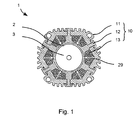
Fig. 1 einen Querschnitt durch einen Elektromotor; -
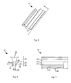
Fig. 2 eine perspektivische Ansicht eines Rückschlussrings des Elektromotors; -
Fig. 3 einen Querschnitt durch den Rückschlussring; -
Fig. 4 einen Längsschnitt durch den Rückschlussring; -
Fig. 5 eine perspektivische Ansicht eines Statorzahns des Elektromotors; -
Fig. 6 einen Querschnitt durch den Statorzahn und -
Fig. 7 eine Seitenansicht des Statorzahns. - Gleiche oder funktionsgleiche Elemente werden durch gleiche Bezugszeichen in den Figuren indiziert, soweit nicht anders angegeben.
- Eine Ausführungsform eines Stators wird unter Bezug auf die
Figuren 1 bis 7 beschrieben. Der beispielhafte Stator 10 kann für einen Elektromotor 1 oder eine andere elektrodynamische Maschine, z.B. einen Generator, verwendet werden. Der Elektromotor kann ein Universalmotor oder ein bürstenloser Elektromotor sein. Ein Rotor 2 und eine Welle 3 des Elektromotors 1 sind schematisch angedeutet. Der Rotor 2 weist wenigstens zwei Pole auf, die durch Spulenwicklungen oder durch Permanentmagnete gebildet werden können. - Der Stator 10 beinhaltet einen Rückschlussring 11, Statorzähne 12 und Wicklungen 13. Um jeden der Statorzähne 12 ist eine der Wicklungen 13 gelegt. Die Anzahl der Statorzähne 12 und damit die Anzahl der Pole des Stators 10 können wie in dem dargestellten Beispiel sechs sein. Es kann jedoch auch eine andere Anzahl, je nach Einsatzgebiet der elektrodynamischen Maschine und der Anzahl der Pole des Rotors 2.
- Ein beispielhafter Aufbau des Rückschlussrings 11 ist perspektivisch in
Fig. 2 dargestellt.Fig. 5 zeigt einen Querschnitt des Rückschlussrings 11 senkrecht zu einer Längsachse 14.Fig. 6 zeigt einen Längsschnitt entlang der inFig. 5 angegebenen Ebene A-A. Der Rückschlussring 11 ist ein zusammenhängender Hohlkörper, gebildet durch eine Wand 15 mit einer Innenfläche 16, einer Außenfläche 17 und zwei einander gegenüberliegenden Stirnflächen 18, 19. - In die Wand 15 sind mehrere Schlitze 20 eingebracht. Die Schlitze 20 verlaufen axial, das heißt parallel zu der Längsachse 14. Im Bereich der Schlitze 20 ist die Wand 15 vollständig entfernt. Seitenwände 27 der Schlitze 20 können im Wesentlichen senkrecht zu der Innenfläche 16 verlaufen. Die Länge 33 der Schlitze 20, bestimmt parallel zur Längsachse 14, kann größer als die Hälfte der Länge 39 des Rückschlussrings 11 sein. Alternativ beträgt die Länge 33 der Schlitze 20 wenigstens zwei Drittel oder wenigstens drei Viertel der Länge 39 des Rückschlussrings 11. Die Schlitze 20 können unterschiedlich lang sein. Die Länge des Schlitzes 20 ist vorzugsweise kürzer als 90%, z.B. 75% der Länge 39 des Rückschlussrings, um eine ausreichende mechanische Stabilität zu gewährleisten.
- In axialer Verlängerung kann sich eine Nut 35 in der Wand 15 an die Schlitze 20 anschließen (beispielhaft dargestellt in der rechten Hälfte von
Fig. 3 ). Die Nut 35 kann an der Innenfläche 16 verlaufen. Die Tiefe 36 der Nut 35 ist geringer als eine Wandstärke 21 der Wand 15. - Die Schlitze 20 beginnen in der dargestellten Ausführungsform alle bei der ersten Stirnfläche 18. Alternativ kann eine erste Gruppe der Schlitze 20 bei der ersten Stirnflächen 18 und eine zweite Gruppe der Schlitze bei der zweiten Stirnflächen 19 beginnen. Die Schlitze 20 können in gleichen Abständen entlang des Umfangs des Rückschlussrings 11 angeordnet sein. In anderen Ausführungsformen können zwei Schlitze 20 paarweise einen geringeren Abstand zueinander als zwischen zwei Paaren der Schlitze 20 aufweisen.
- Der Rückschlussring 11 kann vollständig mit einer Isolationsschicht, z.B. einem Lack, umgeben sein. Die Isolationsschicht kann auch partiell auf wenigstens einem erfolgenden Flächen aufgebracht werden: den Seitenflächen 27 der Schlitze 20, der Innenfläche 16, der Außenfläche 17.
- Der Rückschlussring 11 ist vorzugsweise geblecht, indem mehrere Bleche mit einer Kontur entsprechend dem Querschnitt des Rückschlussrings 11 auf einander gestapelt sind.
Ein Statorzahn 12 ist perspektivisch inFig. 5 , in einem Querschnitt senkrecht zur Längsachse 14 inFig. 6 und in einer Seitenansicht inFig. 7 dargestellt. Der Statorzahn 12 weist einen Steg 23 auf, an dessen einer Seite sich ein Polabschnitt 22 und an einer gegenüberliegenden Seite ein Kopfabschnitt 24 anschließt. Die Höhe 32 des Stegs 23 ist gleich der Wandstärke 21 der Wand 15 im Bereich des Schlitzes 20 gewählt. Der Kopfabschnitt 24 und der Polabschnitt 22 können den Statorzahn 12 formschlüssig mittels eines Umgreifens der Wand 15 durch den Schlitz 20 hindurch befestigen. - Der Statorzahn 12 wird längs in einen der Schlitze 20 des Rückschlussrings 11 eingesetzt, wobei der axial verlaufende Steg 23 in dem Schlitz 20 liegt. Der Steg 23 weist dafür eine Breite 25 auf, die geringer als eine Breite 26 des Schlitzes 20 ist. Vorzugsweise berührt der Steg 23 nicht die Seitenwände 27 des Schlitzes 20. Zwischen dem Steg 23 und dem Schlitz 20 kann ein Luftspalt vorgesehen sein, alternativ ist eine Isolationsschicht aus einem nicht leitenden Kunststoff auf den Seitenwänden 27 vorgesehen.
- Der Polabschnitt 22 kann eine Spulenwicklung 13 in dem Stator 10 fixieren. Eine von dem Steg 23 abgewandte Fläche 28 des Polabschnitts 22 kann beispielsweise derart dimensioniert sein, dass sich die abgewandten Flächen 28 zweier benachbarter Statorzähne 12 in dem Stator 10 berühren oder durch einen schmalen Spalt 29 voneinander getrennt sind.
- Ein Sockel 30 des Polabschnitts 22 ist breiter als der Steg 23 und der Schlitz 20. Der Sockel 30 liegt unmittelbar oder durch eine Isolationsschicht getrennt an der Innenfläche 16 des Rückschlussrings 11 an, wenn der Statorzahn 12 in den Schlitz 20 eingesetzt wird.
- Der Kopfabschnitt 24 ist breiter als der Steg 23 und der Schlitz 20. Der Kopfabschnitt 24 weist eine Anlagefläche 31 auf, die die Außenfläche 17 des Rückschlussrings 11 berührt. Zwischen der Anlagefläche 31 und den Rückschlussring 11 kann eine Isolationsschicht vorgesehen sein.
- Der Kopfabschnitt 24 kann an einer dem Steg 23 zugewandten Fläche 33 längs verlaufende Kerben 34 aufweisen, die an den Steg 23 angrenzen. Die Anlagefläche 31 ist hierdurch in axialer Richtung von dem Schlitz 20 beanstandet.
- Eine Länge 37 des Stegs 23 ist vorzugsweise an die Länge 33 der Schlitze 20 angepasst, z.B. sind die beiden Längen 33, 37 gleichgroß. Der Polabschnitt 22 (Länge 38) kann länger als der Steg 23 sein. Der Polabschnitt 22 kann sich über die gesamte Länge 39 des Rückschlussrings 11 und damit der Stators 10 erstrecken. Eine Länge des Kopfabschnitts 24 kann gleich der Länge 37 des Stegs 23 (dargestellt) oder gleich der Länge 38 des Polabschnitts (nicht dargestellt) gewählt werden.
- In den dargestellten Ausführungsformen beginnen die Schlitze 20 an einer Stirnfläche 18. Dies ermöglicht in einfacher Weise die Statorzähne 12 an dem Rückschlussring 11 zu befestigen. Die Spulenwicklungen 13 können um den Polabschnitt 22 der Statorzähne 13 gewickelt werden, bevor die Statorzähne 12 in den Rückschlussring 11 eingesetzt werden.
- In einer Ausführungsform können die Schlitze 20 zu beiden Stirnflächen 18, 19 hin geschlossen sein. Der Rückschlussring 11 kann dazu beispielsweise aus zwei Teilringen zusammengesetzt werden. Bei wenigstens einem der beiden Teilringe sind die Schlitze 20 an einer Stirnfläche offen. Die Statorzähne 12 können in diesen Teilring eingesetzt werden und wird auf den zweiten Teilring aufgesetzt.
Claims (11)
- Stator (10) für eine elektrodynamische Maschine mit
einem Rückschlussring (11), der wenigstens eine axial verlaufende Nut aufweist, wenigstens einen Statorzahn (12), der formschlüssig in der axial verlaufenden Nut verankert ist,
wobei die axial verlaufende Nut in wenigstens einem Abschnitt zu einem Schlitz (20) ausgebildet ist,
wobei der Statorzahn (12) einen Verankerungsabschnitt (23, 24) aufweist, der den Schlitz (20) durchgreift,
wobei der Verankerungsabschnitt (23, 24) eine erste Anlagefläche (30) an einer Innenseite (16) des Rückschlussrings (11) und eine zweite Anlagefläche (31) an einer Außenseite (17) des Rückschlussrings (11) aufweist,
wobei der Verankerungsabschnitt (23, 24) einen Steg aufweist, dessen Breite (25) geringer als eine Breite (26) des Schlitzes (20) ist,
dadurch gekennzeichnet, dass die zweite Anlagefläche (31) von einem Rand des Schlitzes (20) beabstandet ist. - Stator (10) nach Anspruch 1, dadurch gekennzeichnet, dass eine Abmessung (32) des Stegs (23) senkrecht zu dem Rückschlussring (11) im Bereich des Schlitzes (20) gleich einer Wandstärke (25) des Rückschlussrings (11) im Bereich des Schlitzes (20) ist.
- Stator (10) nach einem der Ansprüche 1 oder 2, dadurch gekennzeichnet, dass eine axiale Abmessung (37) des Verankerungsabschnitts (23, 24) und eine axiale Abmessung (33) des Schlitzes (20) gleich sind.
- Stator (10) nach Anspruch 1, dadurch gekennzeichnet, dass die zweite Anlagefläche (31) durch einen Kopfabschnitt (24) gebildet ist, der auf einer Höhe der zweiten Anlagefläche (31) eine an den Schlitz (20) angrenzende und axial verlaufende Kerbe (34) aufweist.
- Stator (10) nach einem der vorhergehenden Ansprüche, dadurch gekennzeichnet, dass eine axiale Abmessung (33) des Schlitzes (20) wenigstens ein Drittel einer axialen Abmessung (39) des Rückschlussrings (11) beträgt.
- Stator (10) nach einem der vorhergehenden Ansprüche, dadurch gekennzeichnet, dass der Schlitz (20) an einem axialen Ende (18, 19) des Rückschlussrings (11) beginnt.
- Stator (10) nach Anspruch 6, dadurch gekennzeichnet, dass wenigstens zwei Schlitze (20) vorgesehen sind, die an gegenüberliegenden axialen Enden (18, 19) des Schlitzes (20) beginnen.
- Stator (10) nach Anspruch 7, dadurch gekennzeichnet, dass die zwei Schlitze (20) um einen Winkel zueinander versetzt angeordnet sind.
- Stator (10) nach einem der vorhergehenden Ansprüche, dadurch gekennzeichnet, dass zwei Rückschlussringe (11) vorgesehen sind, die jeweils wenigstens einen Schlitz (20) beginnend an einem axialen Ende (18, 19) aufweisen, und die beiden Rückschlussringe (11) derart zueinander orientiert sind, dass die beiden Schlitze (20) ineinander übergehen.
- Stator (10) nach einem der vorhergehenden Ansprüche, dadurch gekennzeichnet, dass der Rückschlussring (11) an einer Außenseite (17) Kühlrippen aufweist.
- Elektrodynamische Maschine gekennzeichnet durch einen Stator (10) nach einem der vorhergehenden Ansprüche.
Applications Claiming Priority (2)
| Application Number | Priority Date | Filing Date | Title |
|---|---|---|---|
| DE200910001588 DE102009001588A1 (de) | 2009-03-17 | 2009-03-17 | Stator für eine elektrodynamische Maschine |
| PCT/EP2010/052933 WO2010105936A2 (de) | 2009-03-17 | 2010-03-09 | Stator für eine elektrodynamische maschine |
Publications (2)
| Publication Number | Publication Date |
|---|---|
| EP2409387A2 EP2409387A2 (de) | 2012-01-25 |
| EP2409387B1 true EP2409387B1 (de) | 2013-06-26 |
Family
ID=42628556
Family Applications (1)
| Application Number | Title | Priority Date | Filing Date |
|---|---|---|---|
| EP10707285.2A Active EP2409387B1 (de) | 2009-03-17 | 2010-03-09 | Stator für eine elektrodynamische maschine |
Country Status (3)
| Country | Link |
|---|---|
| EP (1) | EP2409387B1 (de) |
| DE (1) | DE102009001588A1 (de) |
| WO (1) | WO2010105936A2 (de) |
Family Cites Families (16)
| Publication number | Priority date | Publication date | Assignee | Title |
|---|---|---|---|---|
| DE746360C (de) * | 1939-09-23 | 1944-07-21 | Auto Union A G | Befestigung der Pole im Joch elektrischer Maschinen, insbesondere elektrischer Maschinen fuer Kraftfahrzeuge |
| GB8825071D0 (en) * | 1988-10-26 | 1988-11-30 | Nelco Holdings Ltd | Laminated stators for dynamo electric machines |
| JP2945037B2 (ja) * | 1989-09-29 | 1999-09-06 | 日本サーボ株式会社 | 小型回転電機 |
| JPH0591683A (ja) * | 1991-09-25 | 1993-04-09 | Sanyo Electric Co Ltd | 誘導電動機のステータ装置 |
| DE19629383A1 (de) * | 1996-07-20 | 1998-01-22 | Aweco Kunststofftech Geraete | Ständerblech für den feststehenden Teil einer elektrischen Maschine |
| ITTO980343A1 (it) * | 1998-04-23 | 1999-10-23 | Bitron Spa | Motore elettrico a commutazione elettronica |
| DE19842948A1 (de) * | 1998-09-18 | 2000-03-30 | Siemens Ag | Elektromotor |
| DE10124415A1 (de) * | 2001-05-18 | 2002-11-28 | Siemens Ag | Elektrische Maschine |
| US6573632B2 (en) | 2001-07-06 | 2003-06-03 | Chun-Pu Hsu | Structure of a stator forming an annularly closed stable structure |
| JP4923374B2 (ja) * | 2001-09-26 | 2012-04-25 | 日産自動車株式会社 | 回転電機のステータ構造 |
| JP3986838B2 (ja) * | 2002-01-31 | 2007-10-03 | ミネベア株式会社 | 回転電機 |
| JP3954399B2 (ja) * | 2002-01-31 | 2007-08-08 | ミネベア株式会社 | 回転電機 |
| GB2430085B (en) * | 2003-09-05 | 2008-02-06 | Black & Decker Inc | Field assemblies and methods of making same |
| JP3538422B2 (ja) * | 2003-09-17 | 2004-06-14 | 松下エコシステムズ株式会社 | 内転型電動機の固定子およびその製造方法 |
| DE102004029442A1 (de) * | 2004-06-18 | 2006-01-26 | Minebea Co., Ltd. | Statoranordnung für eine elektrische Maschine |
| JP4476202B2 (ja) * | 2005-09-20 | 2010-06-09 | 山洋電気株式会社 | 永久磁石型回転モータ |
-
2009
- 2009-03-17 DE DE200910001588 patent/DE102009001588A1/de not_active Withdrawn
-
2010
- 2010-03-09 EP EP10707285.2A patent/EP2409387B1/de active Active
- 2010-03-09 WO PCT/EP2010/052933 patent/WO2010105936A2/de not_active Ceased
Also Published As
| Publication number | Publication date |
|---|---|
| WO2010105936A2 (de) | 2010-09-23 |
| DE102009001588A1 (de) | 2010-09-23 |
| WO2010105936A3 (de) | 2011-10-27 |
| EP2409387A2 (de) | 2012-01-25 |
Similar Documents
| Publication | Publication Date | Title |
|---|---|---|
| DE102008023923B4 (de) | Stator, Verfahren zur Herstellung von Statorsegmenten, Verfahren zur Herstellung von einem Stator | |
| WO2013160047A2 (de) | Elektrische maschine | |
| DE19757136A1 (de) | Bürstenloser, elektrisch kommutierter Motor | |
| DE102004027036A1 (de) | Synchronmotor | |
| DE112014004639T5 (de) | Drehende elektrische Maschine und Herstellungsverfahren für diese | |
| DE20115098U1 (de) | Stator mit einer radialen Wicklung | |
| DE102012001118B4 (de) | Elektromaschine | |
| WO2018141656A1 (de) | Stator für einen elektromotor | |
| DE102018111119A1 (de) | Verfahren zum Herstellen einer Wicklung für einen Ständer einer elektrischen Maschine und elektrische Maschine | |
| DE202017100616U1 (de) | Stator für einen Elektromotor | |
| EP2517334B1 (de) | Rotor für eine elektrische maschine | |
| EP1702397B1 (de) | Klauenpolläufer für eine elektrische maschine | |
| DE69010289T2 (de) | Elektrische Reluktanzmaschinen. | |
| DE1638301A1 (de) | Elektrische Maschinen | |
| WO1997016880A2 (de) | Langstator für einen linearmotor und zur herstellung des langstators bestimmtes blechpaket | |
| EP1638186A1 (de) | Stator einer elektrischen Maschine und Verfahren für seiner Herstellung | |
| WO2006084787A1 (de) | Bürstenlose gleichstrommaschine und deren rückschlussringpaket, zahnkranzpaket und kopfteil sowie deren herstellungsverfahren | |
| WO2010105936A2 (de) | Stator für eine elektrodynamische maschine | |
| EP3900156B1 (de) | Blechpaket für eine elektrische maschine | |
| DE102018204395A1 (de) | Wickelkörper für einen elektrischen Antrieb | |
| DE102016200862A1 (de) | Spulenkörper | |
| EP1641104A2 (de) | Wicklungsträger für eine elektrische Maschine | |
| EP4014302B1 (de) | Stator mit optimiertem wickelraum | |
| DE2708429A1 (de) | Elektrokleinmotor mit ausgepraegten polen | |
| DE102011004612A1 (de) | Spule für eine Elektromaschine mit verbessertem Wicklungsfüllfaktor |
Legal Events
| Date | Code | Title | Description |
|---|---|---|---|
| PUAI | Public reference made under article 153(3) epc to a published international application that has entered the european phase |
Free format text: ORIGINAL CODE: 0009012 |
|
| AK | Designated contracting states |
Kind code of ref document: A2 Designated state(s): AT BE BG CH CY CZ DE DK EE ES FI FR GB GR HR HU IE IS IT LI LT LU LV MC MK MT NL NO PL PT RO SE SI SK SM TR |
|
| AX | Request for extension of the european patent |
Extension state: AL BA ME RS |
|
| 17P | Request for examination filed |
Effective date: 20120427 |
|
| RBV | Designated contracting states (corrected) |
Designated state(s): AT BE BG CH CY CZ DE DK EE ES FI FR GB GR HR HU IE IS IT LI LT LU LV MC MK MT NL NO PL PT RO SE SI SK SM TR |
|
| RIC1 | Information provided on ipc code assigned before grant |
Ipc: H02K 1/14 20060101ALI20120427BHEP Ipc: H02K 5/18 20060101AFI20120427BHEP |
|
| DAX | Request for extension of the european patent (deleted) | ||
| GRAP | Despatch of communication of intention to grant a patent |
Free format text: ORIGINAL CODE: EPIDOSNIGR1 |
|
| GRAS | Grant fee paid |
Free format text: ORIGINAL CODE: EPIDOSNIGR3 |
|
| GRAA | (expected) grant |
Free format text: ORIGINAL CODE: 0009210 |
|
| AK | Designated contracting states |
Kind code of ref document: B1 Designated state(s): AT BE BG CH CY CZ DE DK EE ES FI FR GB GR HR HU IE IS IT LI LT LU LV MC MK MT NL NO PL PT RO SE SI SK SM TR |
|
| REG | Reference to a national code |
Ref country code: GB Ref legal event code: FG4D Free format text: NOT ENGLISH |
|
| REG | Reference to a national code |
Ref country code: CH Ref legal event code: EP |
|
| REG | Reference to a national code |
Ref country code: AT Ref legal event code: REF Ref document number: 619062 Country of ref document: AT Kind code of ref document: T Effective date: 20130715 |
|
| REG | Reference to a national code |
Ref country code: IE Ref legal event code: FG4D Free format text: LANGUAGE OF EP DOCUMENT: GERMAN |
|
| REG | Reference to a national code |
Ref country code: DE Ref legal event code: R096 Ref document number: 502010003796 Country of ref document: DE Effective date: 20130822 |
|
| PG25 | Lapsed in a contracting state [announced via postgrant information from national office to epo] |
Ref country code: FI Free format text: LAPSE BECAUSE OF FAILURE TO SUBMIT A TRANSLATION OF THE DESCRIPTION OR TO PAY THE FEE WITHIN THE PRESCRIBED TIME-LIMIT Effective date: 20130626 Ref country code: GR Free format text: LAPSE BECAUSE OF FAILURE TO SUBMIT A TRANSLATION OF THE DESCRIPTION OR TO PAY THE FEE WITHIN THE PRESCRIBED TIME-LIMIT Effective date: 20130927 Ref country code: SE Free format text: LAPSE BECAUSE OF FAILURE TO SUBMIT A TRANSLATION OF THE DESCRIPTION OR TO PAY THE FEE WITHIN THE PRESCRIBED TIME-LIMIT Effective date: 20130626 Ref country code: NO Free format text: LAPSE BECAUSE OF FAILURE TO SUBMIT A TRANSLATION OF THE DESCRIPTION OR TO PAY THE FEE WITHIN THE PRESCRIBED TIME-LIMIT Effective date: 20130926 Ref country code: LT Free format text: LAPSE BECAUSE OF FAILURE TO SUBMIT A TRANSLATION OF THE DESCRIPTION OR TO PAY THE FEE WITHIN THE PRESCRIBED TIME-LIMIT Effective date: 20130626 Ref country code: SI Free format text: LAPSE BECAUSE OF FAILURE TO SUBMIT A TRANSLATION OF THE DESCRIPTION OR TO PAY THE FEE WITHIN THE PRESCRIBED TIME-LIMIT Effective date: 20130626 |
|
| REG | Reference to a national code |
Ref country code: LT Ref legal event code: MG4D |
|
| PG25 | Lapsed in a contracting state [announced via postgrant information from national office to epo] |
Ref country code: HR Free format text: LAPSE BECAUSE OF FAILURE TO SUBMIT A TRANSLATION OF THE DESCRIPTION OR TO PAY THE FEE WITHIN THE PRESCRIBED TIME-LIMIT Effective date: 20130626 Ref country code: BG Free format text: LAPSE BECAUSE OF FAILURE TO SUBMIT A TRANSLATION OF THE DESCRIPTION OR TO PAY THE FEE WITHIN THE PRESCRIBED TIME-LIMIT Effective date: 20130926 |
|
| REG | Reference to a national code |
Ref country code: NL Ref legal event code: VDEP Effective date: 20130626 |
|
| PG25 | Lapsed in a contracting state [announced via postgrant information from national office to epo] |
Ref country code: LV Free format text: LAPSE BECAUSE OF FAILURE TO SUBMIT A TRANSLATION OF THE DESCRIPTION OR TO PAY THE FEE WITHIN THE PRESCRIBED TIME-LIMIT Effective date: 20130626 |
|
| PG25 | Lapsed in a contracting state [announced via postgrant information from national office to epo] |
Ref country code: SK Free format text: LAPSE BECAUSE OF FAILURE TO SUBMIT A TRANSLATION OF THE DESCRIPTION OR TO PAY THE FEE WITHIN THE PRESCRIBED TIME-LIMIT Effective date: 20130626 Ref country code: EE Free format text: LAPSE BECAUSE OF FAILURE TO SUBMIT A TRANSLATION OF THE DESCRIPTION OR TO PAY THE FEE WITHIN THE PRESCRIBED TIME-LIMIT Effective date: 20130626 Ref country code: PT Free format text: LAPSE BECAUSE OF FAILURE TO SUBMIT A TRANSLATION OF THE DESCRIPTION OR TO PAY THE FEE WITHIN THE PRESCRIBED TIME-LIMIT Effective date: 20131028 Ref country code: IS Free format text: LAPSE BECAUSE OF FAILURE TO SUBMIT A TRANSLATION OF THE DESCRIPTION OR TO PAY THE FEE WITHIN THE PRESCRIBED TIME-LIMIT Effective date: 20131026 Ref country code: CY Free format text: LAPSE BECAUSE OF FAILURE TO SUBMIT A TRANSLATION OF THE DESCRIPTION OR TO PAY THE FEE WITHIN THE PRESCRIBED TIME-LIMIT Effective date: 20130807 Ref country code: CZ Free format text: LAPSE BECAUSE OF FAILURE TO SUBMIT A TRANSLATION OF THE DESCRIPTION OR TO PAY THE FEE WITHIN THE PRESCRIBED TIME-LIMIT Effective date: 20130626 |
|
| PG25 | Lapsed in a contracting state [announced via postgrant information from national office to epo] |
Ref country code: PL Free format text: LAPSE BECAUSE OF FAILURE TO SUBMIT A TRANSLATION OF THE DESCRIPTION OR TO PAY THE FEE WITHIN THE PRESCRIBED TIME-LIMIT Effective date: 20130626 Ref country code: NL Free format text: LAPSE BECAUSE OF FAILURE TO SUBMIT A TRANSLATION OF THE DESCRIPTION OR TO PAY THE FEE WITHIN THE PRESCRIBED TIME-LIMIT Effective date: 20130626 Ref country code: RO Free format text: LAPSE BECAUSE OF FAILURE TO SUBMIT A TRANSLATION OF THE DESCRIPTION OR TO PAY THE FEE WITHIN THE PRESCRIBED TIME-LIMIT Effective date: 20130626 Ref country code: ES Free format text: LAPSE BECAUSE OF FAILURE TO SUBMIT A TRANSLATION OF THE DESCRIPTION OR TO PAY THE FEE WITHIN THE PRESCRIBED TIME-LIMIT Effective date: 20131007 |
|
| PG25 | Lapsed in a contracting state [announced via postgrant information from national office to epo] |
Ref country code: CY Free format text: LAPSE BECAUSE OF FAILURE TO SUBMIT A TRANSLATION OF THE DESCRIPTION OR TO PAY THE FEE WITHIN THE PRESCRIBED TIME-LIMIT Effective date: 20130626 |
|
| PG25 | Lapsed in a contracting state [announced via postgrant information from national office to epo] |
Ref country code: DK Free format text: LAPSE BECAUSE OF FAILURE TO SUBMIT A TRANSLATION OF THE DESCRIPTION OR TO PAY THE FEE WITHIN THE PRESCRIBED TIME-LIMIT Effective date: 20130626 |
|
| PLBE | No opposition filed within time limit |
Free format text: ORIGINAL CODE: 0009261 |
|
| STAA | Information on the status of an ep patent application or granted ep patent |
Free format text: STATUS: NO OPPOSITION FILED WITHIN TIME LIMIT |
|
| 26N | No opposition filed |
Effective date: 20140327 |
|
| REG | Reference to a national code |
Ref country code: DE Ref legal event code: R097 Ref document number: 502010003796 Country of ref document: DE Effective date: 20140327 |
|
| PG25 | Lapsed in a contracting state [announced via postgrant information from national office to epo] |
Ref country code: LU Free format text: LAPSE BECAUSE OF FAILURE TO SUBMIT A TRANSLATION OF THE DESCRIPTION OR TO PAY THE FEE WITHIN THE PRESCRIBED TIME-LIMIT Effective date: 20140309 |
|
| REG | Reference to a national code |
Ref country code: CH Ref legal event code: PL |
|
| REG | Reference to a national code |
Ref country code: IE Ref legal event code: MM4A |
|
| PG25 | Lapsed in a contracting state [announced via postgrant information from national office to epo] |
Ref country code: LI Free format text: LAPSE BECAUSE OF NON-PAYMENT OF DUE FEES Effective date: 20140331 Ref country code: CH Free format text: LAPSE BECAUSE OF NON-PAYMENT OF DUE FEES Effective date: 20140331 Ref country code: IE Free format text: LAPSE BECAUSE OF NON-PAYMENT OF DUE FEES Effective date: 20140309 |
|
| REG | Reference to a national code |
Ref country code: FR Ref legal event code: PLFP Year of fee payment: 7 |
|
| PG25 | Lapsed in a contracting state [announced via postgrant information from national office to epo] |
Ref country code: MT Free format text: LAPSE BECAUSE OF FAILURE TO SUBMIT A TRANSLATION OF THE DESCRIPTION OR TO PAY THE FEE WITHIN THE PRESCRIBED TIME-LIMIT Effective date: 20130626 |
|
| PG25 | Lapsed in a contracting state [announced via postgrant information from national office to epo] |
Ref country code: SM Free format text: LAPSE BECAUSE OF FAILURE TO SUBMIT A TRANSLATION OF THE DESCRIPTION OR TO PAY THE FEE WITHIN THE PRESCRIBED TIME-LIMIT Effective date: 20130626 |
|
| REG | Reference to a national code |
Ref country code: AT Ref legal event code: MM01 Ref document number: 619062 Country of ref document: AT Kind code of ref document: T Effective date: 20150309 |
|
| PG25 | Lapsed in a contracting state [announced via postgrant information from national office to epo] |
Ref country code: MC Free format text: LAPSE BECAUSE OF FAILURE TO SUBMIT A TRANSLATION OF THE DESCRIPTION OR TO PAY THE FEE WITHIN THE PRESCRIBED TIME-LIMIT Effective date: 20130626 |
|
| PG25 | Lapsed in a contracting state [announced via postgrant information from national office to epo] |
Ref country code: TR Free format text: LAPSE BECAUSE OF FAILURE TO SUBMIT A TRANSLATION OF THE DESCRIPTION OR TO PAY THE FEE WITHIN THE PRESCRIBED TIME-LIMIT Effective date: 20130626 Ref country code: HU Free format text: LAPSE BECAUSE OF FAILURE TO SUBMIT A TRANSLATION OF THE DESCRIPTION OR TO PAY THE FEE WITHIN THE PRESCRIBED TIME-LIMIT; INVALID AB INITIO Effective date: 20100309 Ref country code: BE Free format text: LAPSE BECAUSE OF FAILURE TO SUBMIT A TRANSLATION OF THE DESCRIPTION OR TO PAY THE FEE WITHIN THE PRESCRIBED TIME-LIMIT Effective date: 20140331 |
|
| PG25 | Lapsed in a contracting state [announced via postgrant information from national office to epo] |
Ref country code: AT Free format text: LAPSE BECAUSE OF NON-PAYMENT OF DUE FEES Effective date: 20150309 |
|
| REG | Reference to a national code |
Ref country code: FR Ref legal event code: PLFP Year of fee payment: 8 |
|
| REG | Reference to a national code |
Ref country code: FR Ref legal event code: PLFP Year of fee payment: 9 |
|
| PG25 | Lapsed in a contracting state [announced via postgrant information from national office to epo] |
Ref country code: MK Free format text: LAPSE BECAUSE OF FAILURE TO SUBMIT A TRANSLATION OF THE DESCRIPTION OR TO PAY THE FEE WITHIN THE PRESCRIBED TIME-LIMIT Effective date: 20130626 |
|
| P01 | Opt-out of the competence of the unified patent court (upc) registered |
Effective date: 20230830 |
|
| PGFP | Annual fee paid to national office [announced via postgrant information from national office to epo] |
Ref country code: DE Payment date: 20250319 Year of fee payment: 16 |
|
| PGFP | Annual fee paid to national office [announced via postgrant information from national office to epo] |
Ref country code: FR Payment date: 20250325 Year of fee payment: 16 |
|
| PGFP | Annual fee paid to national office [announced via postgrant information from national office to epo] |
Ref country code: GB Payment date: 20250321 Year of fee payment: 16 Ref country code: IT Payment date: 20250325 Year of fee payment: 16 |