EP2409355B1 - Batterie à consommation d'oxygène à capacité de régime élevé améliorée - Google Patents
Batterie à consommation d'oxygène à capacité de régime élevé améliorée Download PDFInfo
- Publication number
- EP2409355B1 EP2409355B1 EP10753920.7A EP10753920A EP2409355B1 EP 2409355 B1 EP2409355 B1 EP 2409355B1 EP 10753920 A EP10753920 A EP 10753920A EP 2409355 B1 EP2409355 B1 EP 2409355B1
- Authority
- EP
- European Patent Office
- Prior art keywords
- battery
- cell
- oxygen
- air
- electrode
- Prior art date
- Legal status (The legal status is an assumption and is not a legal conclusion. Google has not performed a legal analysis and makes no representation as to the accuracy of the status listed.)
- Active
Links
Images


Classifications
-
- H—ELECTRICITY
- H01—ELECTRIC ELEMENTS
- H01M—PROCESSES OR MEANS, e.g. BATTERIES, FOR THE DIRECT CONVERSION OF CHEMICAL ENERGY INTO ELECTRICAL ENERGY
- H01M10/00—Secondary cells; Manufacture thereof
- H01M10/42—Methods or arrangements for servicing or maintenance of secondary cells or secondary half-cells
- H01M10/44—Methods for charging or discharging
-
- H—ELECTRICITY
- H01—ELECTRIC ELEMENTS
- H01M—PROCESSES OR MEANS, e.g. BATTERIES, FOR THE DIRECT CONVERSION OF CHEMICAL ENERGY INTO ELECTRICAL ENERGY
- H01M12/00—Hybrid cells; Manufacture thereof
- H01M12/04—Hybrid cells; Manufacture thereof composed of a half-cell of the fuel-cell type and of a half-cell of the primary-cell type
- H01M12/06—Hybrid cells; Manufacture thereof composed of a half-cell of the fuel-cell type and of a half-cell of the primary-cell type with one metallic and one gaseous electrode
- H01M12/065—Hybrid cells; Manufacture thereof composed of a half-cell of the fuel-cell type and of a half-cell of the primary-cell type with one metallic and one gaseous electrode with plate-like electrodes or stacks of plate-like electrodes
-
- H—ELECTRICITY
- H01—ELECTRIC ELEMENTS
- H01M—PROCESSES OR MEANS, e.g. BATTERIES, FOR THE DIRECT CONVERSION OF CHEMICAL ENERGY INTO ELECTRICAL ENERGY
- H01M12/00—Hybrid cells; Manufacture thereof
- H01M12/08—Hybrid cells; Manufacture thereof composed of a half-cell of a fuel-cell type and a half-cell of the secondary-cell type
-
- H—ELECTRICITY
- H01—ELECTRIC ELEMENTS
- H01M—PROCESSES OR MEANS, e.g. BATTERIES, FOR THE DIRECT CONVERSION OF CHEMICAL ENERGY INTO ELECTRICAL ENERGY
- H01M50/00—Constructional details or processes of manufacture of the non-active parts of electrochemical cells other than fuel cells, e.g. hybrid cells
- H01M50/10—Primary casings, jackets or wrappings of a single cell or a single battery
- H01M50/102—Primary casings, jackets or wrappings of a single cell or a single battery characterised by their shape or physical structure
- H01M50/109—Primary casings, jackets or wrappings of a single cell or a single battery characterised by their shape or physical structure of button or coin shape
-
- H—ELECTRICITY
- H01—ELECTRIC ELEMENTS
- H01M—PROCESSES OR MEANS, e.g. BATTERIES, FOR THE DIRECT CONVERSION OF CHEMICAL ENERGY INTO ELECTRICAL ENERGY
- H01M50/00—Constructional details or processes of manufacture of the non-active parts of electrochemical cells other than fuel cells, e.g. hybrid cells
- H01M50/10—Primary casings, jackets or wrappings of a single cell or a single battery
- H01M50/138—Primary casings, jackets or wrappings of a single cell or a single battery adapted for specific cells, e.g. electrochemical cells operating at high temperature
- H01M50/1385—Hybrid cells
-
- H—ELECTRICITY
- H01—ELECTRIC ELEMENTS
- H01M—PROCESSES OR MEANS, e.g. BATTERIES, FOR THE DIRECT CONVERSION OF CHEMICAL ENERGY INTO ELECTRICAL ENERGY
- H01M8/00—Fuel cells; Manufacture thereof
- H01M8/02—Details
-
- Y—GENERAL TAGGING OF NEW TECHNOLOGICAL DEVELOPMENTS; GENERAL TAGGING OF CROSS-SECTIONAL TECHNOLOGIES SPANNING OVER SEVERAL SECTIONS OF THE IPC; TECHNICAL SUBJECTS COVERED BY FORMER USPC CROSS-REFERENCE ART COLLECTIONS [XRACs] AND DIGESTS
- Y02—TECHNOLOGIES OR APPLICATIONS FOR MITIGATION OR ADAPTATION AGAINST CLIMATE CHANGE
- Y02E—REDUCTION OF GREENHOUSE GAS [GHG] EMISSIONS, RELATED TO ENERGY GENERATION, TRANSMISSION OR DISTRIBUTION
- Y02E60/00—Enabling technologies; Technologies with a potential or indirect contribution to GHG emissions mitigation
- Y02E60/10—Energy storage using batteries
-
- Y—GENERAL TAGGING OF NEW TECHNOLOGICAL DEVELOPMENTS; GENERAL TAGGING OF CROSS-SECTIONAL TECHNOLOGIES SPANNING OVER SEVERAL SECTIONS OF THE IPC; TECHNICAL SUBJECTS COVERED BY FORMER USPC CROSS-REFERENCE ART COLLECTIONS [XRACs] AND DIGESTS
- Y02—TECHNOLOGIES OR APPLICATIONS FOR MITIGATION OR ADAPTATION AGAINST CLIMATE CHANGE
- Y02E—REDUCTION OF GREENHOUSE GAS [GHG] EMISSIONS, RELATED TO ENERGY GENERATION, TRANSMISSION OR DISTRIBUTION
- Y02E60/00—Enabling technologies; Technologies with a potential or indirect contribution to GHG emissions mitigation
- Y02E60/30—Hydrogen technology
- Y02E60/50—Fuel cells
Definitions
- This invention relates to oxygen-consuming electrochemical batteries and cells with improved high rate and high power discharge capability, particularly during intermittent use.
- Electrochemical battery cells that use oxygen from outside the cell as an active material to produce electrical energy can be used to power a variety of portable electronic devices.
- Oxygen enters the cell, where it can be used as an active material in the oxygen consuming (e.g., positive) electrode, where the oxygen consuming electrode promotes the reaction of the oxygen with the cell electrolyte and, ultimately, oxidation of the counter (e.g., negative) electrode active material.
- the material in the oxygen consuming electrode that promotes the reaction of oxygen with the electrolyte is often referred to as a catalyst.
- some materials used in these electrodes are not true catalysts because they can be at least partially reduced, particularly during periods of relatively high rate cell discharge.
- an oxygen consuming cell is an oxygen-depolarized metal/air cell in which air from outside the cell enters the cell, and the oxygen is reduced by the positive, or air, electrode.
- the negative electrode active material is a metal, such as zinc, that is oxidized during cell discharge.
- a metal/air cell generally has an aqueous alkaline (e.g., KOH) electrolyte.
- Another example of an oxygen consuming cells is a fuel cell.
- An advantage of an oxygen consuming cell such as a metal/air cell is its high energy density, since at least a portion of the active material of the positive electrode comes from outside the cell, thereby either reducing the cell volume or making more volume available for the negative electrode active material.
- Oxygen consuming cells can have a maximum discharge rate.
- the maximum discharge rate can limited by the rate at which oxygen can enter the oxygen consuming electrode.
- undesirable gases such as carbon dioxide
- Examples of these approaches can be found in U.S. Patent No. 6,558,828 ; U.S. Patent No. 6,492,046 ; U.S. Patent No. 5,795,667 ; U.S. Patent No. 5,733,676 ; U.S. Patent Publication No.
- U.S. Patent Publication No. 2008/0254345 discloses a valve that is operated by an actuator that responds to changes in a potential applied across the actuator to open and close the valve. The rate at which oxygen can enter the cell is minimized when the cell is not being used to provide power, but the valve opens and the rate of oxygen entry into the cell increases as the demand for power increases.
- US3497388 describes an hybrid gas-depolarised cell comprising a dummy load to avoid accumulation of hydrogen when no external load is present.
- US2005/0058887 describes a metal-air battery wherein when the battery is not in use a mechanism inhibits the entrance of air, such as to increase useful life.
- a battery for providing power to operate an electronic device comprises one or more oxygen consuming cells, wherein each of the one or more oxygen-consuming cells consists of a metal-air cell comprising a housing with one or more oxygen entry ports, an first, oxygen consuming, electrode disposed in the housing, a second, counter, electrode disposed in the housing, an electrolyte disposed in the housing, a first electrical contact terminal in electrical contact with the first electrode, and a second electrical contact terminal in electrical contact with the second electrode. Oxygen from outside the housing is able to enter the housing to reach the oxygen consuming electrode.
- an electrical circuit is complete between the first and second terminals of at least one of the oxygen consuming cells, and the electrical circuit comprises a sacrificial drain on the at least one of the oxygen consuming cells.
- a combination of a battery for providing power to operate an electronic device and the electronic device that can be operated by the battery comprises one or more oxygen consuming cells, and the one or more oxygen consuming cells comprise a housing with one or more oxygen entry ports, an first, oxygen consuming, electrode disposed in the housing, a second, counter, electrode disposed in the housing, an electrolyte disposed in the housing, a first electrical contact terminal in electrical contact with the first electrode, and a second electrical contact terminal in electrical contact with the second electrode. Oxygen from outside the housing is able to enter the housing to reach the oxygen consuming electrode.
- an electrical circuit is complete between the first and second terminals of at least one of the oxygen consuming cells, and the electrical circuit comprises a sacrificial drain on the at least one of the oxygen consuming cells.
- the invention includes a battery with at least one oxygen-consuming cell that uses oxygen from outside the cell as an active material for one of the electrodes.
- the cell has an electrode that consumes the oxygen and a counter electrode.
- the cell is a metal-air cell in which the positive electrode (which may be referred to below as a cathode) that reduces the oxygen and a negative electrode (which may be referred to below as a cathode) that contains a metal, such as zinc in a zinc-air cell, as the negative electrode active material that is oxidized during discharge of the cell.
- a zinc-air cell can have an aqueous alkaline electrolyte, such as potassium hydroxide, sodium hydroxide and/or lithium hydroxide in water.
- the cell can be a fuel cell in which the active materials for both electrodes come from outside the cell, and the active material for one of the electrodes is oxygen.
- reaction (I) can take place: (I) CO 2 + 2KOH ⁇ K 2 CO 3 + H 2 O
- the potassium carbonate produced can crystallize if its concentration in the electrolyte present in the air electrode exceeds the saturation limit.
- the solid potassium carbonate may precipitate in the pores of the air electrode and reduce the available reaction area, expand and damage the electrode, block air ingress into the air electrode and reduce the ionic conductivity of the electrolyte.
- the formation of water in reaction I can also increase the vapor pressure of water within the cell and cause loss of water from the cell, which can also contribute to a reduction in the cell rate capability.
- Atmospheric air typically contains about 20.9476 volume percent oxygen and about 0.0314 volume percent carbon dioxide, or about 0.15 volume percent carbon dioxide, based on the volume of oxygen, at 15°C and a pressure of 101325 Pa.
- Carbon dioxide levels at and above the levels typically found in atmospheric air have been found to cause degradation in the rate capability of oxygen-consuming cells, and it is expected that carbon dioxide at lower levels can cause noticeable degradation as well. It is believed that when as little as 0.05 volume percent or less carbon dioxide, based on the volume of oxygen, at 15°C and 101,325 Pa pressure, can also be detrimental when sources of oxygen other than atmospheric air are used.
- a battery is ready for use when it has been removed from packaging in which it was sold, unsealed (e.g., an air access or air entry port covering such as a tab or tape is removed), or installed in an electronic device or other appliance to or from which the battery will be used to provide power.
- the sacrificial drain is present at all times after the cell has been put into use, including those times when the cell is providing power to operate a device, for example.
- the sacrificial drain can be removed, so it is present when the cell is not providing power but not when the cell is providing to operate a device, for example.
- the sacrificial drain can be provided through an electrical circuit that is contained within the battery, or at least part of the circuit can be a part of the device in which the battery is being used.
- the sacrificial drain can be a part of a circuit that can be opened and closed, such as by a switch.
- the switch can be a switch that is also used to turn the device on and off, or it can be a separate switch.
- the switch can be operated manually, or it can be operated electronically.
- a control circuit can be used to open and close the electrical circuit including the sacrificial drain.
- the control circuit can be within the battery, or at least a portion of the control circuit can be within the device.
- the control circuit can also be used to determine a device mode, such that when the device is in a mode that does not draw power from the battery to operate a device function, the sacrificial drain is not connected to the battery. In yet another embodiment the sacrificial drain can be varied.
- a sacrificial discharge that is sufficient, but not substantially more than the minimum required, to reduce the deterioration of rate capability.
- An optimum background drain can be determined empirically through experimentation, depending on the desired minimum rate capability and expected cell use regimen.
- Placing an oxygen consuming cell, into which oxygen can enter and reach the oxygen consuming electrode, on a light sacrificial discharge when the cell is not in use can be particularly advantageous when undesirable fluid impurities such as carbon dioxide are present with the oxygen, as when air is used as a source of oxygen.
- Button cell 10 includes a negative electrode (anode) casing 26 that is generally a cup-shaped metal component.
- Cell 10 includes a positive electrode (cathode) casing 12 that is cup-shaped, and is preferably formed of nickel-plated steel such that it has a relatively flat central region 14 which is continuous with and surrounded by an upstanding wall 16 of uniform height. Alternatively, the central region 14 of the bottom of the cathode casing 12 may protrude outward from the peripheral part of the bottom. At least one hole 18 is present in the bottom of cathode casing 12 to act as an air entry port.
- Prismatic cell 110 includes an anode casing 126 and a cathode casing 112, preferably formed of nickel-plated steel.
- Anode casing 126 and cathode casing 112 are generally prismatic-shaped, and preferably rectangular, with each casing 126, 112 defining four linear or nonlinear sidewalls connected to a base or central region, preferably substantially planar.
- cathode casing 112 can have a base with an area that protrudes outward from the peripheral part of the casing base.
- the casings can include single or multiple steps if desired.
- a positive electrode such as air electrode 20, 120 in a metal/air cell, is disposed in the cathode casing 12, 112, adjacent to the source of the oxygen, such as outside air entry ports 18, 118.
- the air electrode 20, 120 may contain any suitable catalyst material.
- the air electrode 20, 120 can include a mixture of a conductive material such as carbon, a catalytic material such as manganese oxide (MnO x ), and a binder material such as polytetrafluoroethylene (PTFE).
- the air electrode 20, 120 preferably has a hydrophobic, oxygen permeable membrane layer 22, 122, such as a polytetrafluoroethylene (PTFE) film, laminated thereon.
- the PTFE layer 22, 122 is laminated on the side of the air electrode 20, 120 closest to the oxygen source.
- the air electrode 20, 120 can also contain a current collector, such as a metal screen (preferably made of nickel expanded metal) embedded therein on the opposite side of the air electrode 20, 120 from the hydrophobic layer 22, 122.
- the cell 10, 110 can also contain an additional water barrier membrane 23, 123, such as a PTFE film membrane, between the hydrophobic layer 22, 122 and the oxygen source.
- a layer of porous material 21, 121 can be positioned between air electrode 20, 120 and the cathode casing bottom 14, 114 to assist in evenly distribute air to electrode 20, 120.
- a sealant 129 can be used to bond portions of the air electrode to cathode casing 112.
- At least one layer of separator 24, 124 is positioned above air electrode 20, 120, between the air electrode 20, 120 and the negative electrode.
- the anode casing 26, 126 forms the top of cell 10, 110.
- the anode casing 26, 126 preferably has a substrate including a material having a sufficient mechanical strength.
- the casing substrate in one embodiment is a single layer of material such as, but not limited to steel (e.g., stainless steel, mild steel, or cold rolled steel), aluminum, titanium, or copper, with mild steel preferred.
- the anode casing substrate can be pre-plated (plated prior to being formed into a casing) or clad with at least one additional layer.
- Preferred pre-plating and clad materials include, but are not limited to, nickel, copper, indium, tin and combinations thereof that can serve to prevent or minimize corrosion of the substrate.
- the anode casing 26, 126 can be post-plated (plated after being formed into a casing) to provide improved corrosion resistance and/or external appearance.
- at least the inside surface of the formed anode casing 26, 126 comprises an alloy of copper, tin and zinc.
- Pre-plated or clad layers, or both can provide an advantage of preventing any pinholes, damage, or other defects in the post-plated layer from exposing a lower hydrogen overvoltage substrate material, as well as promoting adhesion with subsequently applied layers.
- anode casing 26, 126 can be inverted, and a negative electrode composition or anode mixture 28, 128 and electrolyte are put into anode casing 26, 126.
- the anode mixture insertion can be a two step process wherein dry anode mixture materials are deposited (e.g., dispensed) first into the concave portion of the anode casing 26, 126, followed by KOH solution dispensing, or the wet and dry components of the anode mixture can be blended beforehand and then deposited in one step into the anode casing 26, 126.
- the anode mixture 28, 128 can include zinc and aqueous alkaline electrolyte solution. Small amounts of additives can be included to inhibit gassing in the cell and/or improve performance. Examples include but are not limited to zinc oxide, indium hydroxide, a surfactant, and other organic and inorganic compounds.
- the anode mixture 28,128 can also include a binder or gelling agent.
- Preferred zinc powders are low-gassing zinc compositions, especially for use in cells with no added mercury. Examples are disclosed in U.S. Patent Nos. 6,602,629 (Guo et al. ), 5,464,709 (Getz et al. ) and 5,312,476 (Uemura et al. ), which are hereby incorporated by reference.
- the composition of the anode mixture 28, 128 can be varied to provide the desired processing and cell performance characteristics.
- the cell housing includes the cathode casing 12, 112 and the anode casing 26, 126, which are electrically insulated from and sealed to each other.
- the housing can include a gasket 30, 130 made from an electrically nonconductive, elastomeric material to provide the seal.
- the bottom edge of the gasket 30, 130 can have an inwardly facing lip 32, 132, which abuts the rim of anode casing 26, 126.
- a sealant may be applied to the sealing surface of the gasket 30, 130, cathode casing 12, 112 and/or anode casing 26, 126.
- the cathode casing 12, 112 including the inserted air electrode 20, 120, can be inverted and pressed downward against the anode cup/gasket assembly, which is preassembled with the anode casing 26, 126 inverted so the rim of the anode casing 26, 126 faces upward. While inverted, the edge of the cathode casing 12, 112 is deformed inwardly, so the rim 34, 134 of the cathode casing 12, 112 is compressed against the gasket 30, 130 to form a seal and an electrically insulating barrier between the anode casing 26, 126 and the cathode casing 12, 112.
- a suitable tab (not shown) can be placed over the opening 18, 118 until the cell 10, 110 is ready for use to keep air from entering the cell 10 before use.
- the cell 10, 110 can be sealed in an airtight pouch or other container until ready for use.
- the rate of oxygen entering the cell 10, 110 can be limited by the number, size and locations of the openings 18, 188 in the cathode casing 12, 112. In some embodiments the rate of oxygen entry into the cell 10, 110 can be further controlled, such as by a fluid regulating system.
- the battery can also have a fluid regulating system for adjusting the rate of passage of oxygen to the positive electrode (e.g., the air electrode in an air-depolarized and cell) to provide a sufficient amount of oxygen from outside the cell for discharge of the cell at high rate or high power, while minimizing entry of other gases into the positive electrode and water gain or loss into or from the cell during periods of low rate or no discharge.
- the fluid regulating system can be relatively simple, such as a manually operated valve that is open when the battery is in use and closed when it is not, or it may be much more complex, such as the valve disclosed in US 2008/0254345 , which is hereby incorporated by reference.
- the fluid regulating system can be located within the cell, within a battery containing the cell, within a device in which the battery is installed, or portions of the fluid regulating system can be located in more than one of the cell, the battery and the device.
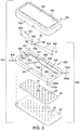
- a battery 140 includes cell 100 and a fluid regulating system 150.
- Casing 112 has a bottom surface 114 in which one or more air entry ports 118 are provided such that oxygen may pass to the interior of the cell housing so as to reach the positive electrode 40, and fluid regulating system 150 is secured to the exterior of bottom surface 114 of casing 112.
- the fluid regulating system 150 may include a valve with a first plate 62 having a plurality of apertures 64 and a movable second plate 66 including a plurality of apertures 68 that correspond in size, shape, number, and position to apertures 64 formed in first plate 62.
- the size, shape, number, and position of apertures 64 and 68 are preferably optimized to provide the desired volume and distribution of fluid applied to the fluid consuming electrode.
- the size, shape, number and relative location of apertures, 64 do not have to be the same as the size, shape, number and relative location of apertures 68. For example, if apertures 64 are slightly different in size from apertures 68, precise alignment of apertures 64 and 68 is not essential to achieve the maximum total open area through plates 62 and 66.
- Fluid regulating system 150 includes a chassis 550 with an electrically conductive frame and components integrally formed therein.
- the electrically conductive frame and the electrical components assembled thereon are substantially encapsulated within electrically non-conductive chassis 550.
- the chassis 550 generally defines a central opening 555 and includes an inward extending ledge 552.
- the periphery of the moving plate 66 is positioned on and abuts the bottom surface of the inward extending ledge 552.
- the chassis 550 has ribs 554 which extend across the opening 555 above the moving plate 66.
- the ribs 554 are shown generally formed in V-shape extending diagonally through opening 555 and serve to hold the central portion of the moving plate 66 flat above the underlying fixed plate 62.
- the fixed plate 62 is connected to the bottom side of the chassis 550, and the cell 100 is connected to the top side of the chassis 550.
- fluid e.g., oxygen and other gases
- the valve when the valve is open.
- the chassis 550 is further illustrated having crimp connector openings 560 formed in desired locations and adapted to receive crimps 562 of the shape memory alloy (SMA) wire actuators 82a and 82b.
- the crimp connector openings 560 may be integrally formed during formation of the chassis 550 or may be subsequently formed by removing material (e.g., machining or etching) to form the desired opening shape and size.
- Extending from each of the crimp connector openings 560 are respective circuit elements of the frame 500 that serve as contact pads 520. Contact pads 520 are formed as part of the electrically conductive circuit elements of the frame 500 and are adapted to make electrical contact with the SMA wire actuators 82a and 82b to apply electrical current thereto.
- the frame 500 further includes a plurality of circuit elements that serve as battery contacts 530, 532, 534a, 534b, 536a and 536b extending from the chassis 550, each of which is adapted to be bent into contact with a terminal of the cell 100.
- the contacts 530, 532, 534a, 534b, 536a and 536b can extend from the corners, as shown, or from other portions of the chassis 550.
- the fluid regulating system 150 includes a valve actuator including first and second SMA wires 82a and 82b.
- SMA wires 82a and 82b are connected to lever 84 by way of arcuate slots 564.
- the first SMA wire 82a extends between end crimps 562 and one slot 564 and may be activated to pull the lever 84 in one direction to open the valve, while the second SMA wire 82b is connected between end crimps 562 and the other slot 564 to pull lever 84 in the opposite direction to close the valve.
- Lever 84 includes an actuator pin 88 which engages moving plate 66 to move the plate 66 between the open and closed valve positions as discussed herein.
- valve actuator is shown and described herein employing two SMA wires 82a and 82b connected via respective arcuate slots 564 to a lever 84, it should be appreciated that other types and arrangements of valve actuators may be employed to actuate the moving plate 66 relative to the fixed plate 62 to open and close the valve. Further, it should be appreciated that while a generally linear actuation of moving plate 66 is shown and described herein, other configurations of valves may be employed to control the flow of oxygen to the cell 100.
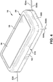
- the cell 100 is assembled to the top surface of the chassis 550 as seen in Fig. 4 .
- the battery contacts are bent upwards and into contact with appropriate terminals of the cell 100.
- battery contacts 530, 534a and 534b are bent upwards and into contact with the side wall of the can 34 which forms the positive terminal.
- the battery contact 532 (not seen) likewise makes contact with the side wall of the casing 112 forming the positive terminal.
- the remaining battery contacts 536a and 536b are bent upwards and into contact with the casing 126 forming the negative terminal of the cell 100.
- An underlying electrically insulating tape 580 is applied below battery contacts 536a and 536b on the side wall of the casing 112 so as to electrically insulate contacts 536a and 536b from the positive battery terminal.
- the battery contacts 536a and 536b extend further beyond insulating tape 580 onto and in contact with the casing 126 forming the negative battery terminal.
- An overlying electrically insulating tape 582 is then applied over the battery contacts 536a and 536b as seen in Fig. 5 .
- the fluid regulating system is incorporated into a device that can be powered by an oxygen-depolarized cell or a battery containing one or more cells.
- an oxygen depolarized cell or battery is installed in a device, and one or more components of the device restrict the flow of air from the external environment to the cell/battery. This can be done by positioning a flow restricting material between the point(s) of entry of air into to cell/battery and the exterior of the device, such that the maximum rate of flow of air to the cell/battery is less than an unimpeded rate of flow into the cell/battery.
- FIG. 6 An example is shown in Fig. 6 , in which a battery consisting of one cell 100 is installed in a device 610.
- Cell 100 is inverted with the anode casing 126, which serves as the negative contact terminal, facing the interior of the battery compartment 616.
- the device 610 has a housing 612 with top, bottom and side walls and an opening 614 leading to the battery compartment 616 formed in the housing 612.
- the battery compartment 616 includes the opening 614 configured with a size and shape adapted to receive one or more cells 100. While a single cell 100 is illustrated, the device 610 can employ one or more individual cells 100 or a battery containing one or a plurality of cells 100.
- the device 610 generally includes electrical connections (not shown) that allow for electrical contact to be made between each of the cells 100 and electrical circuitry within the device 610.
- the electrical connections may include conductive contacts arranged in the battery compartment 616 so as to make contact with the side of cathode casing 112 and the downward facing surface of anode casing 126.
- cover 618 that defines a top surface over the battery compartment 616.
- the cover may be opened by a user to allow access to the battery compartment 16 and may be closed to cover the battery compartment 616 and cell 100.
- cover 618 may include a locking tab 622 that engages a slot 624 in the device housing 612 to hold the cover 618 in the closed position. The user may actuate the tab 622 to disengage the connection with slot 624 and pivot the cover 618 to an open position, when the cell 100 needs to be removed and/or inserted.
- the device 610 comprises an air manager in the form of a fluid flow restricting material 630 adhered to the interior surface of cover 618.
- the fluid flow restricting material 630 is shown as a single layer, fluid permeable and compressible material that provides fluid management between the outside environment and the air entry ports 118 of the cell 100.
- the material 630 provides a fluid seal against the top face of the cell 100 when the cover 618 is in the closed position. The seal provided by the material 630 may allow for permeation of air through the thickness of material 630 from openings 620 in the cover 618 to the air entry ports 118 in the cell 100, while preventing substantial fluid flow from the lateral sides of the material 630.
- the material 630 may provided a first permeation path of a first permeation rate from the openings 620 to air entry ports 118 and a second permeation path from the lateral sides of material 630 at a second permeation rate, such that air may transfer in axially from the side, if desired.
- the openings to the battery compartment 616 can be located outside the interface between the cover 618 and the material 630, such as in another surface of the battery compartment 616, and/or a gap between the cover 618 and the opening 614 can function as an opening for air to enter the battery compartment 616.
- the material 630 provides a permeation path from a lateral side of the material 630 to the air entry ports 118.
- the material 630 may be configured in different ways, depending upon the application of the device 610, so as to have different air permeation rates for different devices.
- the fluid flow restricting material 630 can a loose layer, it can be adhered to the adjacent surface 114 of the cell 100, or it can be adhered to the inside surface of cover 618 by way of an adhesive layer 632.
- the adhesive of layer 632 may include an acrylic based adhesive, for example. By adhering the fluid flow restricting material 630 to the inside surface of the cover 618, the material 630 may be easily used with different cells or batteries as different cells or batteries are installed into and exchanged from the device 610.
- the adhesive 632 may be arranged on the fluid flow restricting material 630 so as not to block the openings 620 in the cover 618.
- the adhesive 632 may cover the openings 620 and may be selected to act as a fluid permeation control layer having a desired air or fluid permeation to regulate fluid flowing therethrough.
- the fluid flow restricting material can be adhered to another interior surface of the battery compartment 616; openings 620 can be located in the lid 614 or another portion of the battery compartment, and/or a gap between the cover 618 and the opening 614 can function as a fluid entry port.
- the fluid flow restricting material 630 can have a shape and size similar to the adjacent surface 114 of the cell 100 and consume the volume of space between the cover 618 and the cell 100, particularly in the area between the air entry ports 42 and cover openings 620, when the cover 618 is closed.
- the fluid flow restricting material 630 controls fluid access based on the fluid permeability of the material 630.
- the fluid flow restricting material 630 is compressed between the inside surface of the cover 618 and the adjacent surface 114 of the cell 100 to provide for a fluid seal against the surface 114 of the cell 100.
- the fluid flow restricting material 630 is a compressible foam that allows for dimensional variations in the cell 100 and battery compartment 616, including cover 618.
- the fluid flow restricting material 630 restricts the flow of fluid from the outside atmosphere to the cell 100 at a controlled fluid permeation rate.
- the fluid flow restricting material 630 may be a foam material that is compressible and air restrictive and has one or more layers that act as a throttling mechanism for fluid to pass to the cell 100 in the device 610.
- the fluid restrictive material 630 also provides a predictable and reproducible seal against the surface 114 of the cell 100 and assures and maintains the fluid seal by way of compression due to the resiliency of the foam material 630.
- the surface of the foam material 630 against the cell 100 can restrict air diffusion, while the bulk of the material 630 can be highly non-restrictive to air.
- the surface of the bulk material opposite the formation of the seal to the cell 100 can be reliably secured to a device compartment wall, such as cover 618, by way of an adhesive; however, other suitable means of securing the material 630 can be used.
- a device compartment wall such as cover 618
- other suitable means of securing the material 630 can be used.
- the types of materials that the fluid restrictive material 630 may employ can vary, as the air seal requirements may vary as a function of the type of device and its application.
- the foam material 630 may have an added skin layer on one or both sides, and one skin layer may be in contact with the surface 114 of the cell 100.
- the additional skin layer may include fluid restricting material, such as silicon rubber, to minimize lateral fluid (e.g., air) leakage (i.e., leakage at the interface between the foam layer 630 and the surface 114 of the cell 100).
- the air permeability of the foam material 630 and an added skin layer may be the same or may be different materials, such that the skin layer is a more restricting material that provides the air flow control.
- the foam layer 630 may be formed with one or more skin layers by altering the foam material 630 with heat and/or chemicals to achieve a desired air permeation control layer. By melting or dissolving the surface of the foam material 630 to reduce the porosity thereof, a desired air or other fluid permeability may be achieved.
- the cathode casing was made from nickel plated steel, the anode casing was made from triclad nickel-stainless steel-copper with the copper layer on the inner surface, and a thermoplastic polymer gasket.
- the air electrode included a catalytic mixture containing a manganese oxide catalyst, carbon to provide electrical conductivity, and a polytetrafluoroethylene (PTFE) binder; a nickel expanded metal current collector; and a hydrophobic layer made from PTFE film laminated onto the side of the electrode facing the air entry ports in the cathode casing.
- PTFE polytetrafluoroethylene
- a layer of PTFE film was placed adjacent to the air electrode, and a porous paper was placed adjacent to the air entry ports.
- the anode included a mixture of unamalgamated zinc powder, aqueous potassium hydroxide electrolyte, a crosslinked sodium polyacrylate binder, and additives, including indium hydroxide, zinc oxide, and an anionic surfactant.
- the separator included two layers of polypropylene film - a hydrophobic polypropylene membrane adjacent to the air electrode and a water-wettable non-woven polypropylene membrane adjacent to the negative electrode, with an adhesive containing a polyvinyl alcohol and a synthetic cellulose gum between the air electrode and the hydrophobic separator layer and between the hydrophobic and water-wettable separator layer.
- the cells were divided into three lots, Lot 1 had all air entry ports in the cathode casing exposed, Lot 2 had all air entry ports except one in the center of the cell covered with a relatively non-porous polyester film tape with a silicone based adhesive, and Lot 3 had all air entry ports covered with a relatively porous medical tape to provide three levels of air access to the cells. This was done to simulate conditions in a device where the rate of air available to the cells was limited to varying degrees, due to limited air access to the battery compartment of the device or throttling of air access by an air manager incorporated into a device, battery or cell. The cells were tested by measuring limiting current to determine the relative rate of oxygen entry to the air electrodes and the rate capability for each lot.
- Rate capabilities were determined in terms of limiting (steady state) current that can be delivered by fully open cells (i.e., with tape removed from cells in Lots 2 and 3) after 30 seconds at a constant voltage of 1.1 volt.
- the limiting current of selected cells from each lot was tested initially, and the remaining cells were then stored at room temperature and about 50 percent relative humidity. Periodically cells were removed from storage and tested for limiting current.
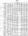
- the results are summarized in the Table below, which shows the average limiting current in mA for each lot of cells after storage for the times listed. The differences in initial (0 months) limiting current among the three lots were due to normal variability.
- the limiting current for Lot 1 with no restrictions on air entering the cells, dropped to 4 mA after 6 months.
- the limiting current for Lot 2 with the air entering the cells being restricted compared to the cells in Lot 1, also dropped with time, but at a slower rate than for Lot 1.
- Example 1 Additional cells from each of Lots 1, 2 and 3 in Example 1 were stored at room temperature and about 50 percent relative humidity, with various resistors placed across the terminals of the cells. The cells were periodically tested to determine voltage and limiting current. Limiting current was tested as described in Example 1. From the voltage measurements and resistances used, corresponding cell currents were calculated, the average current over time was used to estimate the total capacity used, and the discharge capacity remaining was estimated from the calculated total capacity used and a predetermined average discharge capacity per cell.
- Fig. 7 provides a graphical comparison for Lot 2 of the limiting current as a function of storage time for cells without resistors and cells with resistors (ranging from about 7,000 to 14,000 ohms) that provided the best improvement (i.e., least degradation) in limiting current over time.
- Fig. 8 provides similar comparisons for Lot 3 with and without 6,000 to 11,000 ohm resistors. Figs. 7 and 8 show a substantial reduction in the rate of degradation of limiting current when cells were placed on a light sacrificial discharge using a resistor.
- Fig. 9 is a partial summary of cell voltages
- Fig. 10 is a partial summary of remaining capacity for cells in Lots 1, 2 and 3 stored with resistors across their terminals.
- a light sacrificial discharge can be used to substantially reduce the degradation in both cell voltage and rate capability that occurs over time after the cell has been activated.
- a light sacrificial discharge consumes a portion of the cell discharge capacity over time, so it is desirable to use as light of a sacrificial discharge as possible.
- the advantages of maintaining higher voltages and rate capabilities over time are best balanced against the disadvantages of consuming discharge capacity for a desired application to provide the best overall battery performance.
- testing can be done under different conditions besides those in the Examples above to help in the selection of the most suitable sacrificial discharge, depending on the environments in which the battery and device are expected to be used.
Claims (14)
- Batterie destinée à fournir de l'énergie électrique pour faire fonctionner un dispositif électronique, la batterie comprenant un ou plusieurs éléments consommateurs d'oxygène, dans laquelle chacun de l'un ou plusieurs éléments consommateurs d'oxygène consiste en un élément métal-air comprenant un boîtier comportant un ou plusieurs orifices d'entrée d'oxygène, une première électrode consommatrice d'oxygène disposée dans le boîtier, une deuxième contre-électrode disposée dans le boîtier, un électrolyte disposé dans le boîtier, une première borne de contact électrique en contact électrique avec la première électrode, et une deuxième borne de contact électrique en contact électrique avec la deuxième électrode, dans laquelle :de l'oxygène provenant de l'extérieur du boîtier est capable de pénétrer dans le boîtier pour atteindre l'électrode consommatrice d'oxygène ;quand la batterie est prête à l'emploi et ne fournit pas d'énergie électrique pour faire fonctionner le dispositif électronique, le circuit électronique est complet entre la première et la deuxième bornes d'au moins l'un des éléments consommateurs d'oxygène ;le circuit électrique comprend un drain sacrificiel sur l'au moins un des éléments consommateurs d'oxygène.
- Batterie telle que définie par la revendication 1, dans laquelle l'électrolyte est un électrolyte alcalin aqueux.
- Batterie telle que définie par la revendication 2, dans laquelle l'électrolyte comprend de l'hydroxyde de potassium.
- Batterie telle que définie par l'une quelconque des revendications précédentes, dans laquelle la vitesse à laquelle l'oxygène est capable de pénétrer dans le boîtier est en outre restreinte à une valeur inférieure à la vitesse à laquelle l'oxygène est capable de pénétrer dans le boîtier quand les orifices d'entrée d'air ne sont pas restreints.
- Batterie telle que définie par l'une quelconque des revendications précédentes, dans laquelle le drain sacrificiel est lui aussi présent quand la batterie fournit une énergie électrique pour faire fonctionner le dispositif.
- Combinaison de la batterie telle que définie par l'une quelconque des revendications précédentes et du dispositif électronique qui peut être alimenté en énergie électrique par la batterie.
- Combinaison de la batterie et du dispositif électronique telle que définie par la revendication 6, dans laquelle le circuit électrique comprenant le drain sacrificiel est une partie de la batterie.
- Combinaison de la batterie et du dispositif électronique telle que définie par la revendication 6, dans laquelle le circuit électrique comprenant le drain sacrificiel est une partie du dispositif.
- Combinaison de la batterie et du dispositif électronique telle que définie par l'une quelconque des revendications 6 à 8, dans laquelle le circuit électronique comprenant le drain sacrificiel peut être ouvert et fermé.
- Combinaison de la batterie et du dispositif électronique telle que définie par la revendication 9, dans laquelle le circuit électrique comprenant le drain sacrificiel peut être ouvert et fermé par un interrupteur à fonctionnement manuel.
- Combinaison de la batterie et du dispositif électronique telle que définie par la revendication 10, dans laquelle l'interrupteur est utilisé pour mettre le dispositif en marche et à l'arrêt.
- Combinaison de la batterie et du dispositif électronique telle que définie par la revendication 9, dans laquelle le circuit électrique comprenant le drain sacrificiel peut être ouvert et fermé par voie électronique.
- Combinaison de la batterie et du dispositif électronique telle que revendiquée par la revendication 12, dans laquelle le circuit électrique comprenant le drain sacrificiel peut être ouvert ou fermé par un circuit de commande.
- Combinaison de la batterie et du dispositif électronique telle que définie par la revendication 13, dans laquelle le circuit de commande détermine un mode du dispositif.
Applications Claiming Priority (2)
| Application Number | Priority Date | Filing Date | Title |
|---|---|---|---|
| US16046909P | 2009-03-16 | 2009-03-16 | |
| PCT/US2010/027276 WO2010107679A2 (fr) | 2009-03-16 | 2010-03-15 | Batterie à consommation d'oxygène à capacité de régime élevé améliorée |
Publications (3)
| Publication Number | Publication Date |
|---|---|
| EP2409355A2 EP2409355A2 (fr) | 2012-01-25 |
| EP2409355A4 EP2409355A4 (fr) | 2013-08-07 |
| EP2409355B1 true EP2409355B1 (fr) | 2017-09-13 |
Family
ID=42740175
Family Applications (1)
| Application Number | Title | Priority Date | Filing Date |
|---|---|---|---|
| EP10753920.7A Active EP2409355B1 (fr) | 2009-03-16 | 2010-03-15 | Batterie à consommation d'oxygène à capacité de régime élevé améliorée |
Country Status (6)
| Country | Link |
|---|---|
| US (1) | US8309260B2 (fr) |
| EP (1) | EP2409355B1 (fr) |
| JP (1) | JP2013522810A (fr) |
| KR (1) | KR20120137460A (fr) |
| CN (1) | CN102356508B (fr) |
| WO (1) | WO2010107679A2 (fr) |
Families Citing this family (11)
| Publication number | Priority date | Publication date | Assignee | Title |
|---|---|---|---|---|
| EP2469620B1 (fr) | 2010-12-24 | 2013-08-14 | swissbatt AG | Batterie |
| US10270142B2 (en) * | 2011-11-07 | 2019-04-23 | Energizer Brands, Llc | Copper alloy metal strip for zinc air anode cans |
| US9821314B2 (en) | 2012-09-24 | 2017-11-21 | Cornell University | Methods, systems, and applications for solar-thermal microfluidic PCR |
| WO2014074504A1 (fr) | 2012-11-06 | 2014-05-15 | Cornell University | Batterie métal-oxygène assistée par le dioxyde de carbone et procédé correspondant |
| CN103986212B (zh) * | 2014-05-28 | 2016-01-20 | 广东欧珀移动通信有限公司 | 腕带式产品充电器 |
| US9454016B1 (en) * | 2015-03-06 | 2016-09-27 | Hutchinson Technology Incorporated | Camera lens suspension with integrated electrical leads |
| US11380923B2 (en) * | 2015-09-17 | 2022-07-05 | Intelligent Energy Limited | Oxygen regulated fuel cell |
| US10320007B2 (en) * | 2016-07-27 | 2019-06-11 | Honeywell International Inc. | Fuel cell having oxygen selective membrane |
| WO2018059845A1 (fr) * | 2016-09-27 | 2018-04-05 | Varta Microbattery Gmbh | Pile bouton zinc/air |
| US20220190409A1 (en) * | 2019-02-12 | 2022-06-16 | The Trustees Of The University Of Pennsylvania | Metal air scavenger - an energy harvesting technology for powering electronics and robotics |
| US11695176B2 (en) | 2020-05-06 | 2023-07-04 | Revolution Power Inc. | Zinc-air battery compositions and methods |
Family Cites Families (26)
| Publication number | Priority date | Publication date | Assignee | Title |
|---|---|---|---|---|
| US3497388A (en) * | 1965-12-30 | 1970-02-24 | Gen Electric | Hybrid gas-depolarized electrical power unit |
| US4262062A (en) * | 1980-03-24 | 1981-04-14 | Timex Corporation | Metal-air battery with environment control for intermittent high current demand |
| CA2046148C (fr) | 1990-08-14 | 1997-01-07 | Dale R. Getz | Cellules alcalines a peu pres exempte de mercure |
| US5312476A (en) | 1991-02-19 | 1994-05-17 | Matsushita Electric Industrial Co., Ltd. | Zinc alloy powder for alkaline cell and method for production of the same |
| US5733676A (en) | 1995-05-05 | 1998-03-31 | Rayovac Corporation | Metal-air cathode can and electrochemical cell made therewith |
| US5795667A (en) | 1995-05-05 | 1998-08-18 | Rayovac Corporation | Metal-air cathode can, and electrochemical cell made therewith |
| US6410997B1 (en) * | 1998-04-17 | 2002-06-25 | Sarnoff Corporation | Power source for a hearing aid |
| CO5060451A1 (es) * | 1998-05-18 | 2001-07-30 | Procter & Gamble | Bateria de cinc/oxigeno que contiene un concentrados de oxigeno |
| US6492046B1 (en) | 1999-08-13 | 2002-12-10 | The Gillette Company | Metal-air battery |
| US6641947B1 (en) | 1999-09-21 | 2003-11-04 | The Gillette Company | Air manager system for metal air battery |
| TW434927B (en) | 1999-11-03 | 2001-05-16 | Ind Tech Res Inst | Method for fabricating metal-air battery and its structure |
| US6602629B1 (en) | 2000-05-24 | 2003-08-05 | Eveready Battery Company, Inc. | Zero mercury air cell |
| US6558828B1 (en) | 2000-05-26 | 2003-05-06 | Eveready Battery Company, Inc. | Zn/air cell performance in extreme humidity by controlling hydrophobic layer porosity |
| AU2002213329A1 (en) | 2000-10-20 | 2002-05-06 | The Gillette Company | Battery |
| US20020150814A1 (en) | 2001-02-01 | 2002-10-17 | Causton Brian Edward | Battery |
| CA2355535A1 (fr) | 2001-08-22 | 2003-02-22 | Aluminum-Power, Inc. | Batteries a metal/gaz |
| JP3895960B2 (ja) * | 2001-10-03 | 2007-03-22 | 本田技研工業株式会社 | 燃料電池スタック |
| US6773842B2 (en) | 2002-03-26 | 2004-08-10 | Nanotek Instruments, Inc. | Metal-air battery with an extended service life |
| US7740965B2 (en) * | 2003-08-01 | 2010-06-22 | The Gillette Company | Battery |
| NZ562278A (en) * | 2005-04-29 | 2010-01-29 | Eveready Battery Inc | Alkaline cell anode casing |
| US7625672B2 (en) * | 2005-10-28 | 2009-12-01 | The Gillette Company | Zinc/air cell |
| US7875390B2 (en) * | 2005-11-22 | 2011-01-25 | Panasonic Corporation | Alkaline battery and method for producing the same |
| JP2008010230A (ja) * | 2006-06-28 | 2008-01-17 | Matsushita Electric Ind Co Ltd | 空気電池システム |
| US20080226976A1 (en) * | 2006-11-01 | 2008-09-18 | Eveready Battery Company, Inc. | Alkaline Electrochemical Cell with Reduced Gassing |
| US7618739B2 (en) | 2007-04-11 | 2009-11-17 | Eveready Battery Co., Inc. | Battery and fluid regulating system having chassis with molded electronics |
| JP4967890B2 (ja) * | 2007-05-01 | 2012-07-04 | トヨタ自動車株式会社 | 空気電池システム |
-
2010
- 2010-03-15 EP EP10753920.7A patent/EP2409355B1/fr active Active
- 2010-03-15 CN CN201080012317.7A patent/CN102356508B/zh not_active Expired - Fee Related
- 2010-03-15 WO PCT/US2010/027276 patent/WO2010107679A2/fr active Application Filing
- 2010-05-11 KR KR1020117017975A patent/KR20120137460A/ko not_active Application Discontinuation
- 2010-05-11 JP JP2012500848A patent/JP2013522810A/ja active Pending
-
2011
- 2011-07-11 US US13/179,637 patent/US8309260B2/en active Active
Non-Patent Citations (1)
| Title |
|---|
| None * |
Also Published As
| Publication number | Publication date |
|---|---|
| JP2013522810A (ja) | 2013-06-13 |
| WO2010107679A3 (fr) | 2011-01-13 |
| US20110269030A1 (en) | 2011-11-03 |
| KR20120137460A (ko) | 2012-12-21 |
| EP2409355A4 (fr) | 2013-08-07 |
| US8309260B2 (en) | 2012-11-13 |
| CN102356508B (zh) | 2016-04-13 |
| EP2409355A2 (fr) | 2012-01-25 |
| CN102356508A (zh) | 2012-02-15 |
| WO2010107679A2 (fr) | 2010-09-23 |
Similar Documents
| Publication | Publication Date | Title |
|---|---|---|
| EP2409355B1 (fr) | Batterie à consommation d'oxygène à capacité de régime élevé améliorée | |
| EP2064771B1 (fr) | Pile électrochimique dotée d'une électrode à air et d'un joint à levier précontraint | |
| EP1685616B1 (fr) | Batterie a consommation de fluide pourvue d'un systeme de regulation de fluide | |
| EP2135322B1 (fr) | Gestionnaire de fluide de batterie utilisant des composants d'alliage à mémoire de forme à des températures d'actionnement différentes | |
| JP4294313B2 (ja) | 金属空気電池カートリッジ | |
| US10211450B2 (en) | Systems and methods for a battery | |
| AU2006262463B2 (en) | Air cell with modified sealing tab | |
| US6461763B1 (en) | Battery cartridge | |
| WO2001054211A9 (fr) | Batterie a regeneration par l'air | |
| JP2004512656A (ja) | 電池 | |
| US20080076024A1 (en) | Battery having pre-compressed air electrode assembly | |
| JP2004512655A (ja) | 電池 | |
| EP2361447B1 (fr) | Dispositif doté d'une batterie alimentée en fluide et dispositif de gestion de fluide | |
| CA2356395A1 (fr) | Cellule elcetrochimique metal-air a fuites reduites | |
| EP1860719B1 (fr) | Batterie à consommation de fluide comportant un système de régulation de fluide | |
| EP1142055A1 (fr) | Elements d'accumulateur metal-air sous pression |
Legal Events
| Date | Code | Title | Description |
|---|---|---|---|
| PUAI | Public reference made under article 153(3) epc to a published international application that has entered the european phase |
Free format text: ORIGINAL CODE: 0009012 |
|
| 17P | Request for examination filed |
Effective date: 20110718 |
|
| AK | Designated contracting states |
Kind code of ref document: A2 Designated state(s): AT BE BG CH CY CZ DE DK EE ES FI FR GB GR HR HU IE IS IT LI LT LU LV MC MK MT NL NO PL PT RO SE SI SK SM TR |
|
| DAX | Request for extension of the european patent (deleted) | ||
| REG | Reference to a national code |
Ref country code: HK Ref legal event code: DE Ref document number: 1164548 Country of ref document: HK |
|
| A4 | Supplementary search report drawn up and despatched |
Effective date: 20130704 |
|
| RIC1 | Information provided on ipc code assigned before grant |
Ipc: H01M 12/08 20060101ALI20130628BHEP Ipc: H01M 12/06 20060101AFI20130628BHEP Ipc: H01M 2/10 20060101ALI20130628BHEP Ipc: H01M 10/44 20060101ALI20130628BHEP |
|
| RAP1 | Party data changed (applicant data changed or rights of an application transferred) |
Owner name: ENERGIZER BRANDS, LLC |
|
| REG | Reference to a national code |
Ref country code: DE Ref legal event code: R079 Ref document number: 602010045222 Country of ref document: DE Free format text: PREVIOUS MAIN CLASS: H01M0012060000 Ipc: H01M0002020000 |
|
| GRAP | Despatch of communication of intention to grant a patent |
Free format text: ORIGINAL CODE: EPIDOSNIGR1 |
|
| INTG | Intention to grant announced |
Effective date: 20170330 |
|
| RIC1 | Information provided on ipc code assigned before grant |
Ipc: H01M 12/08 20060101ALI20170320BHEP Ipc: H01M 12/06 20060101ALI20170320BHEP Ipc: H01M 2/02 20060101AFI20170320BHEP |
|
| GRAS | Grant fee paid |
Free format text: ORIGINAL CODE: EPIDOSNIGR3 |
|
| GRAA | (expected) grant |
Free format text: ORIGINAL CODE: 0009210 |
|
| AK | Designated contracting states |
Kind code of ref document: B1 Designated state(s): AT BE BG CH CY CZ DE DK EE ES FI FR GB GR HR HU IE IS IT LI LT LU LV MC MK MT NL NO PL PT RO SE SI SK SM TR |
|
| REG | Reference to a national code |
Ref country code: GB Ref legal event code: FG4D |
|
| REG | Reference to a national code |
Ref country code: CH Ref legal event code: EP |
|
| REG | Reference to a national code |
Ref country code: IE Ref legal event code: FG4D |
|
| REG | Reference to a national code |
Ref country code: AT Ref legal event code: REF Ref document number: 928948 Country of ref document: AT Kind code of ref document: T Effective date: 20171015 |
|
| REG | Reference to a national code |
Ref country code: DE Ref legal event code: R096 Ref document number: 602010045222 Country of ref document: DE |
|
| REG | Reference to a national code |
Ref country code: NL Ref legal event code: MP Effective date: 20170913 |
|
| REG | Reference to a national code |
Ref country code: LT Ref legal event code: MG4D |
|
| PG25 | Lapsed in a contracting state [announced via postgrant information from national office to epo] |
Ref country code: LT Free format text: LAPSE BECAUSE OF FAILURE TO SUBMIT A TRANSLATION OF THE DESCRIPTION OR TO PAY THE FEE WITHIN THE PRESCRIBED TIME-LIMIT Effective date: 20170913 Ref country code: SE Free format text: LAPSE BECAUSE OF FAILURE TO SUBMIT A TRANSLATION OF THE DESCRIPTION OR TO PAY THE FEE WITHIN THE PRESCRIBED TIME-LIMIT Effective date: 20170913 Ref country code: NO Free format text: LAPSE BECAUSE OF FAILURE TO SUBMIT A TRANSLATION OF THE DESCRIPTION OR TO PAY THE FEE WITHIN THE PRESCRIBED TIME-LIMIT Effective date: 20171213 Ref country code: HR Free format text: LAPSE BECAUSE OF FAILURE TO SUBMIT A TRANSLATION OF THE DESCRIPTION OR TO PAY THE FEE WITHIN THE PRESCRIBED TIME-LIMIT Effective date: 20170913 Ref country code: FI Free format text: LAPSE BECAUSE OF FAILURE TO SUBMIT A TRANSLATION OF THE DESCRIPTION OR TO PAY THE FEE WITHIN THE PRESCRIBED TIME-LIMIT Effective date: 20170913 |
|
| REG | Reference to a national code |
Ref country code: AT Ref legal event code: MK05 Ref document number: 928948 Country of ref document: AT Kind code of ref document: T Effective date: 20170913 |
|
| PG25 | Lapsed in a contracting state [announced via postgrant information from national office to epo] |
Ref country code: GR Free format text: LAPSE BECAUSE OF FAILURE TO SUBMIT A TRANSLATION OF THE DESCRIPTION OR TO PAY THE FEE WITHIN THE PRESCRIBED TIME-LIMIT Effective date: 20171214 Ref country code: BG Free format text: LAPSE BECAUSE OF FAILURE TO SUBMIT A TRANSLATION OF THE DESCRIPTION OR TO PAY THE FEE WITHIN THE PRESCRIBED TIME-LIMIT Effective date: 20171213 Ref country code: LV Free format text: LAPSE BECAUSE OF FAILURE TO SUBMIT A TRANSLATION OF THE DESCRIPTION OR TO PAY THE FEE WITHIN THE PRESCRIBED TIME-LIMIT Effective date: 20170913 Ref country code: ES Free format text: LAPSE BECAUSE OF FAILURE TO SUBMIT A TRANSLATION OF THE DESCRIPTION OR TO PAY THE FEE WITHIN THE PRESCRIBED TIME-LIMIT Effective date: 20170913 |
|
| PG25 | Lapsed in a contracting state [announced via postgrant information from national office to epo] |
Ref country code: NL Free format text: LAPSE BECAUSE OF FAILURE TO SUBMIT A TRANSLATION OF THE DESCRIPTION OR TO PAY THE FEE WITHIN THE PRESCRIBED TIME-LIMIT Effective date: 20170913 |
|
| PG25 | Lapsed in a contracting state [announced via postgrant information from national office to epo] |
Ref country code: CZ Free format text: LAPSE BECAUSE OF FAILURE TO SUBMIT A TRANSLATION OF THE DESCRIPTION OR TO PAY THE FEE WITHIN THE PRESCRIBED TIME-LIMIT Effective date: 20170913 Ref country code: PL Free format text: LAPSE BECAUSE OF FAILURE TO SUBMIT A TRANSLATION OF THE DESCRIPTION OR TO PAY THE FEE WITHIN THE PRESCRIBED TIME-LIMIT Effective date: 20170913 Ref country code: RO Free format text: LAPSE BECAUSE OF FAILURE TO SUBMIT A TRANSLATION OF THE DESCRIPTION OR TO PAY THE FEE WITHIN THE PRESCRIBED TIME-LIMIT Effective date: 20170913 |
|
| PG25 | Lapsed in a contracting state [announced via postgrant information from national office to epo] |
Ref country code: EE Free format text: LAPSE BECAUSE OF FAILURE TO SUBMIT A TRANSLATION OF THE DESCRIPTION OR TO PAY THE FEE WITHIN THE PRESCRIBED TIME-LIMIT Effective date: 20170913 Ref country code: AT Free format text: LAPSE BECAUSE OF FAILURE TO SUBMIT A TRANSLATION OF THE DESCRIPTION OR TO PAY THE FEE WITHIN THE PRESCRIBED TIME-LIMIT Effective date: 20170913 Ref country code: IT Free format text: LAPSE BECAUSE OF FAILURE TO SUBMIT A TRANSLATION OF THE DESCRIPTION OR TO PAY THE FEE WITHIN THE PRESCRIBED TIME-LIMIT Effective date: 20170913 Ref country code: IS Free format text: LAPSE BECAUSE OF FAILURE TO SUBMIT A TRANSLATION OF THE DESCRIPTION OR TO PAY THE FEE WITHIN THE PRESCRIBED TIME-LIMIT Effective date: 20180113 Ref country code: SM Free format text: LAPSE BECAUSE OF FAILURE TO SUBMIT A TRANSLATION OF THE DESCRIPTION OR TO PAY THE FEE WITHIN THE PRESCRIBED TIME-LIMIT Effective date: 20170913 Ref country code: SK Free format text: LAPSE BECAUSE OF FAILURE TO SUBMIT A TRANSLATION OF THE DESCRIPTION OR TO PAY THE FEE WITHIN THE PRESCRIBED TIME-LIMIT Effective date: 20170913 |
|
| REG | Reference to a national code |
Ref country code: DE Ref legal event code: R097 Ref document number: 602010045222 Country of ref document: DE |
|
| PLBE | No opposition filed within time limit |
Free format text: ORIGINAL CODE: 0009261 |
|
| STAA | Information on the status of an ep patent application or granted ep patent |
Free format text: STATUS: NO OPPOSITION FILED WITHIN TIME LIMIT |
|
| PG25 | Lapsed in a contracting state [announced via postgrant information from national office to epo] |
Ref country code: DK Free format text: LAPSE BECAUSE OF FAILURE TO SUBMIT A TRANSLATION OF THE DESCRIPTION OR TO PAY THE FEE WITHIN THE PRESCRIBED TIME-LIMIT Effective date: 20170913 |
|
| 26N | No opposition filed |
Effective date: 20180614 |
|
| REG | Reference to a national code |
Ref country code: HK Ref legal event code: WD Ref document number: 1164548 Country of ref document: HK |
|
| REG | Reference to a national code |
Ref country code: CH Ref legal event code: PL |
|
| GBPC | Gb: european patent ceased through non-payment of renewal fee |
Effective date: 20180315 |
|
| PG25 | Lapsed in a contracting state [announced via postgrant information from national office to epo] |
Ref country code: SI Free format text: LAPSE BECAUSE OF FAILURE TO SUBMIT A TRANSLATION OF THE DESCRIPTION OR TO PAY THE FEE WITHIN THE PRESCRIBED TIME-LIMIT Effective date: 20170913 Ref country code: MC Free format text: LAPSE BECAUSE OF FAILURE TO SUBMIT A TRANSLATION OF THE DESCRIPTION OR TO PAY THE FEE WITHIN THE PRESCRIBED TIME-LIMIT Effective date: 20170913 |
|
| REG | Reference to a national code |
Ref country code: BE Ref legal event code: MM Effective date: 20180331 |
|
| REG | Reference to a national code |
Ref country code: IE Ref legal event code: MM4A |
|
| PG25 | Lapsed in a contracting state [announced via postgrant information from national office to epo] |
Ref country code: LU Free format text: LAPSE BECAUSE OF NON-PAYMENT OF DUE FEES Effective date: 20180315 |
|
| PG25 | Lapsed in a contracting state [announced via postgrant information from national office to epo] |
Ref country code: IE Free format text: LAPSE BECAUSE OF NON-PAYMENT OF DUE FEES Effective date: 20180315 |
|
| PG25 | Lapsed in a contracting state [announced via postgrant information from national office to epo] |
Ref country code: GB Free format text: LAPSE BECAUSE OF NON-PAYMENT OF DUE FEES Effective date: 20180315 Ref country code: LI Free format text: LAPSE BECAUSE OF NON-PAYMENT OF DUE FEES Effective date: 20180331 Ref country code: CH Free format text: LAPSE BECAUSE OF NON-PAYMENT OF DUE FEES Effective date: 20180331 Ref country code: BE Free format text: LAPSE BECAUSE OF NON-PAYMENT OF DUE FEES Effective date: 20180331 |
|
| PG25 | Lapsed in a contracting state [announced via postgrant information from national office to epo] |
Ref country code: FR Free format text: LAPSE BECAUSE OF NON-PAYMENT OF DUE FEES Effective date: 20180331 |
|
| PG25 | Lapsed in a contracting state [announced via postgrant information from national office to epo] |
Ref country code: MT Free format text: LAPSE BECAUSE OF NON-PAYMENT OF DUE FEES Effective date: 20180315 |
|
| PG25 | Lapsed in a contracting state [announced via postgrant information from national office to epo] |
Ref country code: TR Free format text: LAPSE BECAUSE OF FAILURE TO SUBMIT A TRANSLATION OF THE DESCRIPTION OR TO PAY THE FEE WITHIN THE PRESCRIBED TIME-LIMIT Effective date: 20170913 |
|
| PG25 | Lapsed in a contracting state [announced via postgrant information from national office to epo] |
Ref country code: HU Free format text: LAPSE BECAUSE OF FAILURE TO SUBMIT A TRANSLATION OF THE DESCRIPTION OR TO PAY THE FEE WITHIN THE PRESCRIBED TIME-LIMIT; INVALID AB INITIO Effective date: 20100315 Ref country code: PT Free format text: LAPSE BECAUSE OF FAILURE TO SUBMIT A TRANSLATION OF THE DESCRIPTION OR TO PAY THE FEE WITHIN THE PRESCRIBED TIME-LIMIT Effective date: 20170913 |
|
| PG25 | Lapsed in a contracting state [announced via postgrant information from national office to epo] |
Ref country code: CY Free format text: LAPSE BECAUSE OF FAILURE TO SUBMIT A TRANSLATION OF THE DESCRIPTION OR TO PAY THE FEE WITHIN THE PRESCRIBED TIME-LIMIT Effective date: 20170913 Ref country code: MK Free format text: LAPSE BECAUSE OF NON-PAYMENT OF DUE FEES Effective date: 20170913 |
|
| REG | Reference to a national code |
Ref country code: DE Ref legal event code: R079 Ref document number: 602010045222 Country of ref document: DE Free format text: PREVIOUS MAIN CLASS: H01M0002020000 Ipc: H01M0050100000 |
|
| PGFP | Annual fee paid to national office [announced via postgrant information from national office to epo] |
Ref country code: DE Payment date: 20230117 Year of fee payment: 14 |
|
| P01 | Opt-out of the competence of the unified patent court (upc) registered |
Effective date: 20230523 |