EP2409136B1 - Vorrichtung und verfahren zur optischen erfassung von stoffen oder umweltbedingungen - Google Patents
Vorrichtung und verfahren zur optischen erfassung von stoffen oder umweltbedingungen Download PDFInfo
- Publication number
- EP2409136B1 EP2409136B1 EP10712785.4A EP10712785A EP2409136B1 EP 2409136 B1 EP2409136 B1 EP 2409136B1 EP 10712785 A EP10712785 A EP 10712785A EP 2409136 B1 EP2409136 B1 EP 2409136B1
- Authority
- EP
- European Patent Office
- Prior art keywords
- sensing elements
- sensing
- indicator
- wavelength
- elements
- Prior art date
- Legal status (The legal status is an assumption and is not a legal conclusion. Google has not performed a legal analysis and makes no representation as to the accuracy of the status listed.)
- Not-in-force
Links
Images


Classifications
-
- G—PHYSICS
- G01—MEASURING; TESTING
- G01N—INVESTIGATING OR ANALYSING MATERIALS BY DETERMINING THEIR CHEMICAL OR PHYSICAL PROPERTIES
- G01N21/00—Investigating or analysing materials by the use of optical means, i.e. using sub-millimetre waves, infrared, visible or ultraviolet light
- G01N21/75—Systems in which material is subjected to a chemical reaction, the progress or the result of the reaction being investigated
- G01N21/77—Systems in which material is subjected to a chemical reaction, the progress or the result of the reaction being investigated by observing the effect on a chemical indicator
-
- G—PHYSICS
- G01—MEASURING; TESTING
- G01N—INVESTIGATING OR ANALYSING MATERIALS BY DETERMINING THEIR CHEMICAL OR PHYSICAL PROPERTIES
- G01N33/00—Investigating or analysing materials by specific methods not covered by groups G01N1/00 - G01N31/00
- G01N33/0004—Gaseous mixtures, e.g. polluted air
- G01N33/0009—General constructional details of gas analysers, e.g. portable test equipment
- G01N33/0027—General constructional details of gas analysers, e.g. portable test equipment concerning the detector
- G01N33/0036—General constructional details of gas analysers, e.g. portable test equipment concerning the detector specially adapted to detect a particular component
- G01N33/0054—Ammonia
-
- G—PHYSICS
- G01—MEASURING; TESTING
- G01N—INVESTIGATING OR ANALYSING MATERIALS BY DETERMINING THEIR CHEMICAL OR PHYSICAL PROPERTIES
- G01N21/00—Investigating or analysing materials by the use of optical means, i.e. using sub-millimetre waves, infrared, visible or ultraviolet light
- G01N21/75—Systems in which material is subjected to a chemical reaction, the progress or the result of the reaction being investigated
- G01N21/77—Systems in which material is subjected to a chemical reaction, the progress or the result of the reaction being investigated by observing the effect on a chemical indicator
- G01N21/7703—Systems in which material is subjected to a chemical reaction, the progress or the result of the reaction being investigated by observing the effect on a chemical indicator using reagent-clad optical fibres or optical waveguides
- G01N2021/7706—Reagent provision
- G01N2021/7723—Swelling part, also for adsorption sensor, i.e. without chemical reaction
-
- G—PHYSICS
- G01—MEASURING; TESTING
- G01N—INVESTIGATING OR ANALYSING MATERIALS BY DETERMINING THEIR CHEMICAL OR PHYSICAL PROPERTIES
- G01N21/00—Investigating or analysing materials by the use of optical means, i.e. using sub-millimetre waves, infrared, visible or ultraviolet light
- G01N21/75—Systems in which material is subjected to a chemical reaction, the progress or the result of the reaction being investigated
- G01N21/77—Systems in which material is subjected to a chemical reaction, the progress or the result of the reaction being investigated by observing the effect on a chemical indicator
- G01N21/7703—Systems in which material is subjected to a chemical reaction, the progress or the result of the reaction being investigated by observing the effect on a chemical indicator using reagent-clad optical fibres or optical waveguides
- G01N2021/7706—Reagent provision
- G01N2021/773—Porous polymer jacket; Polymer matrix with indicator
-
- G—PHYSICS
- G01—MEASURING; TESTING
- G01N—INVESTIGATING OR ANALYSING MATERIALS BY DETERMINING THEIR CHEMICAL OR PHYSICAL PROPERTIES
- G01N21/00—Investigating or analysing materials by the use of optical means, i.e. using sub-millimetre waves, infrared, visible or ultraviolet light
- G01N21/75—Systems in which material is subjected to a chemical reaction, the progress or the result of the reaction being investigated
- G01N21/77—Systems in which material is subjected to a chemical reaction, the progress or the result of the reaction being investigated by observing the effect on a chemical indicator
- G01N2021/7769—Measurement method of reaction-produced change in sensor
- G01N2021/7773—Reflection
-
- G—PHYSICS
- G01—MEASURING; TESTING
- G01N—INVESTIGATING OR ANALYSING MATERIALS BY DETERMINING THEIR CHEMICAL OR PHYSICAL PROPERTIES
- G01N21/00—Investigating or analysing materials by the use of optical means, i.e. using sub-millimetre waves, infrared, visible or ultraviolet light
- G01N21/75—Systems in which material is subjected to a chemical reaction, the progress or the result of the reaction being investigated
- G01N21/77—Systems in which material is subjected to a chemical reaction, the progress or the result of the reaction being investigated by observing the effect on a chemical indicator
- G01N2021/7769—Measurement method of reaction-produced change in sensor
- G01N2021/7783—Transmission, loss
-
- G—PHYSICS
- G01—MEASURING; TESTING
- G01N—INVESTIGATING OR ANALYSING MATERIALS BY DETERMINING THEIR CHEMICAL OR PHYSICAL PROPERTIES
- G01N21/00—Investigating or analysing materials by the use of optical means, i.e. using sub-millimetre waves, infrared, visible or ultraviolet light
- G01N21/75—Systems in which material is subjected to a chemical reaction, the progress or the result of the reaction being investigated
- G01N21/77—Systems in which material is subjected to a chemical reaction, the progress or the result of the reaction being investigated by observing the effect on a chemical indicator
- G01N2021/7793—Sensor comprising plural indicators
-
- G—PHYSICS
- G01—MEASURING; TESTING
- G01N—INVESTIGATING OR ANALYSING MATERIALS BY DETERMINING THEIR CHEMICAL OR PHYSICAL PROPERTIES
- G01N21/00—Investigating or analysing materials by the use of optical means, i.e. using sub-millimetre waves, infrared, visible or ultraviolet light
- G01N21/75—Systems in which material is subjected to a chemical reaction, the progress or the result of the reaction being investigated
- G01N21/77—Systems in which material is subjected to a chemical reaction, the progress or the result of the reaction being investigated by observing the effect on a chemical indicator
- G01N2021/7796—Special mountings, packaging of indicators
-
- Y—GENERAL TAGGING OF NEW TECHNOLOGICAL DEVELOPMENTS; GENERAL TAGGING OF CROSS-SECTIONAL TECHNOLOGIES SPANNING OVER SEVERAL SECTIONS OF THE IPC; TECHNICAL SUBJECTS COVERED BY FORMER USPC CROSS-REFERENCE ART COLLECTIONS [XRACs] AND DIGESTS
- Y02—TECHNOLOGIES OR APPLICATIONS FOR MITIGATION OR ADAPTATION AGAINST CLIMATE CHANGE
- Y02A—TECHNOLOGIES FOR ADAPTATION TO CLIMATE CHANGE
- Y02A50/00—TECHNOLOGIES FOR ADAPTATION TO CLIMATE CHANGE in human health protection, e.g. against extreme weather
- Y02A50/20—Air quality improvement or preservation, e.g. vehicle emission control or emission reduction by using catalytic converters
Definitions
- the present invention relates to a device and method for optical sensing of substances or environmental conditions.
- Ammonia is an extremely important bulk chemical widely used in fertilizers, plastics and explosives, and also implemented as a coolant in large industrial refrigeration systems. On the other hand it is a toxic and flammable gas and therefore needs to be monitored. Ammonia is also listed as one of the marker molecules in breath that could be used to identify diseases like Uremia and kidney impairment.
- US Patent No. 6897965 to Ghadiri et al. discloses an approach for substance detection in which a layer of porous silicon (PSi) is impregnated with an indicator material of which the refractive index changes when it is exposed to the corresponding substance. The change in the refractive index of the layer is detected as a shift in the reflected interference pattern generated by the layer.
- PSi porous silicon
- the present invention provides a device and corresponding method for optical sensing of substances or environmental conditions in a fluid, as defined in the claims.
- a device for optical sensing of substances or environmental conditions in a fluid comprising: a plurality of non-overlapping adjacent sensing elements, each of the sensing elements comprising a layered optical element for generating a wavelength-specific interference effect, wherein each of the layered optical elements is treated so as to be responsive to presence of a predefined substance or a predefined environmental condition to cause an optically detectable change, and wherein the sensing elements are distinct from each other both in the wavelength-specific interference effect and in the optically detectable change such that, when the device is illuminated by a common illumination beam of multi-wavelength illumination, spectral analysis performed on the reflected or transmitted illumination enables simultaneous sensing of a plurality of substances or environmental conditions.
- the layered optical element includes at least one layer of porous silicon.
- the sensing elements are distinguished by a depth thickness of the at least one layer of porous silicon.
- At least one of the sensing elements is treated by deploying an indicator at least partially within pores of the at least one layer of porous silicon.
- At least one of the sensing elements is treated by oxidation of surfaces of the at least one layer of porous silicon.
- the layered optical element of each sensing element includes at least one layer of thickness between 0.2 and 10 microns.
- At least one of the sensing elements is treated by association of an indicator with the sensing element.
- the indicator is a primary structural component of at least one layer of the layered optical element.
- the indicator of at least one of the sensing elements comprises a temperature responsive material.
- the indicator of at least one of the sensing elements comprises a pressure responsive material.
- the indicator of at least one of the sensing elements is responsive to presence of the predefined substance or the predefined environmental condition to undergo a color change in absorption spectrum.
- the indicator of at least one of the sensing elements is responsive to presence of the predefined substance or the predefmed environmental condition to undergo a change in refractive index.
- the indicator of at least one of the sensing elements is responsive to presence of the predefined substance or the predefined environmental condition to undergo a change in dimensions.
- the indicator of at least one of the sensing elements comprises at least one of the group consisting of: pH sensitive dyes, porphyrins, metalloporphyrins, proteins, anti-bodies and DNA.
- the plurality of sensing elements includes at least three sensing elements.
- the plurality of sensing elements includes at least four sensing elements.
- a reference element arranged in non-overlapping relation adjacent to the plurality of sensing elements, the reference elements comprising a layered optical element for generating a wavelength-specific interference effect distinct from the wavelength-specific interference effect of each of the sensing elements, the reference element being provided without an indicator so as to provide a calibration reference when illuminated together with the sensing elements.
- the plurality of sensing elements are integrated onto a common semiconductor chip.
- an illumination arrangement directing multi-wavelength light simultaneously towards all of the reference elements.
- a spectral analysis arrangement deployed to receive and separate the spectral components of light reflected from or transmitted through the sensing elements, thereby identifying the spectral features corresponding to each sensing and/or reference element, and detecting changes in those spectral features indicative of the state of the indicator of each sensor element.
- a method for sensing substances or environmental conditions in a fluid comprising: (a) providing the device defined above; (b) directing multi-wavelength light simultaneously towards all of the reference elements; and (c) separating the spectral components of light reflected from or transmitted through the sensing elements, thereby identifying the spectral features corresponding to each sensing and/or reference element, and detecting changes in those spectral features indicative of the state of the indicator of each sensor element.
- An embodiment of the present invention is a device and corresponding method for simultaneous optical sensing of several substances or environmental conditions in a fluid.
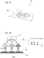
- FIG. 1A illustrates schematically a device, generally designated 10 , constructed and operative according to the teachings of an embodiment of the present invention, for simultaneous optical sensing of several substances or environmental conditions in a fluid ((liquid or gas phase).
- Device 10 includes a plurality of non-overlapping adjacent sensing elements 12 .
- Each sensing element 12 includes a layered optical element for generating a wavelength-specific interference effect.
- Each sensing element is treated, such as by provision of an indicator associated with the layered optical element, so as to be responsive to presence of a predefined substance or a predefined environmental condition to cause an optically detectable change.
- sensing elements 12 are implemented as regions of porous silicon (PSi), and an indicator is impregnated within the pores of the PSi.
- PSi porous silicon
- Each of the sensing elements is distinct from all others of the sensing element, both in the wavelength-specific interference effect and in the optically detectable change, such that, when the device is illuminated by a common illumination beam of multi-wavelength illumination, spectral analysis performed on the reflected or transmitted illumination enables simultaneous sensing of a plurality of substances.
- device 10 essentially functions as a sensor array in which each section is made of porous silicon with a different functionality, such as a different immobilized indicator dye.
- the PSi film may differ in thickness and/or porosity, so that the thin-film reflection spectrum of each of the array components varies in periodicity. This periodicity distinction effectively encodes the spectrum in such a way that the distinct variations can be analyzed using spectral data analysis methods.
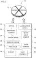
- FIG. 2 shows schematically an exemplary non-limiting implementation of an interrogation device, generally designated 14, for reading device 10.
- Reading of the device may be performed by collimating white light from white light source 16 via illumination optics 18 to illuminate all of sensing elements 12 at once.
- Light reflected from the sensing elements is collected by receiving optics 20 and conveyed, typically via a single fiber, to a spectrometer, represented here schematically by dispersive element 22, sensor array 24 and read interface 26. Since no imaging is implemented in the light collection, the obtained spectrum consists of many overlapping interference spectra each reflected from a different sensing element.
- the sensed data is processed by a processor 28, applying a FFT algorithm to the combined spectrum.
- FIG. 1B illustrates schematically the principles underlying the spectral encoding approach exemplified herein.
- three different sensing regions labeled 12 a , 12 b and 12 c , respectively, are implemented as layers of differing thicknesses, giving rise to reflected interference patterns with correspondingly different characteristic frequency variation patterns.
- the overall reflected spectral response is illustrated at 13.
- a peak corresponding to each sensing element can be clearly distinguished. Variations in the amplitude, shape or position of this peak can then be used to track variations in optical properties of an indicator or other optical variables associated with the corresponding sensor element. It is preferably that peaks in the Fourier-transformed spectrum for each porous silicon sensor will be spread apart to allow good material discrimination. The location of the peak depends on the refractive index (porosity) and the thickness of the layers, and these parameters are easily controlled in the electro-chemical processing of porous silicon, as is known in the art.
- an element "treated so as to be responsive to presence of a predefined substance or a predefined environmental condition to cause an optically detectable change” this refers to any treatment, whether by chemical or physical processing of the optical layered structure itself or by addition thereto of a supplementary material to imbue the structure with the required variable optical properties.
- the optically detectable change is not necessarily sufficient to provide direct data regarding the substance or environmental condition, and may need to be combined with additional data, for example, measurements of other interrelated parameters by other sensing elements, as will be exemplified below with reference to the ammonia sensor example.
- the response to the presence of a substance or parameter may be a binary (e.g., threshold) response, or may be a continuous (quantitative) response.
- predefined substance or predefined environmental condition encompasses all sorts of chemical and physical conditions including, but not limited to, presence of a given element, compound or combination of compounds, more general chemical conditions, such as pH, oxidizing or reducing conditions, and physical parameters such as temperature, pressure, ionizing or non-ionizing radiation of various types.
- At least two predefined substances or predefined environmental conditions this refers to at least two all together, i.e., at least two substances only, at least two environmental conditions only, or at least one substance and at least one environmental condition. "At least three" or any other number should also be interpreted similarly.
- the sensor elements When referring to the sensor elements as being “adjacent”, this refers to elements sufficiently close to facilitate simultaneous illumination with an interrogation light beam.
- the sensor elements are most preferably located in a close packed arrangement with each sensor element within about 10% of its own maximum dimension from its neighboring sensor elements.
- non-overlapping is used here to refer to elements of which the surface can be illuminated directly at the same time without the illuminating beam passing through another of the sensing elements, in contrast to the stacked sensor structures of Pacholski and Ruminski mentioned above.
- layered optical element in this context is used to refer to any structure having one or more layer disposed thereon, either as a uniform layer or with internal structure, so as to generate a wavelength-specific interference effect.
- a multi-layer structure may be used, made up of many layers each with slightly different optical and/or chemical properties.
- Widelength-specific in this context refers to any optical response which has distinctive wavelength dependence at one or more specific wavelengths or wavelength bands.
- non-imaging Various preferred implementations of the reading arrangement for use in the present invention are referred to as "non-imaging" in the sense that dispersive element 22 receives simultaneously light reflected or transmitted by more than one sensing element 12 .
- At least one of the layered optical element includes at least one layer of porous silicon.
- the different sensing elements are preferably distinguished by a thickness of the at least one layer of porous silicon.
- the use of porous silicon allows deployment of an indicator material at least partially within pores of the layer of porous silicon.
- each sensing element includes at least one layer of thickness between 0.2 and 10 microns.
- the optically detectable change occurring in the sensing elements 12 may be one or more of a number of different types of change. Examples include, but are not limited to, a change in the absorption spectrum (within or beyond the visible range), a change in refractive index, and a change in layer thickness.
- the indicator of at least one of the sensing elements includes a temperature responsive material.
- temperature responsive materials include thermochromic materials, such as:
- the indicator of at least one of the sensing elements includes a pressure responsive material.
- a pressure responsive material examples include barochromic materials such as:
- an indicator associated with at least one of the sensing elements is responsive to presence of the predefined substance or the predefined environmental condition to undergo a change in spectral response. This may express itself as a color change, or as any other change in the relative intensities of wavelengths in absorbed, reflected or transmitted light, whether visible or non-visible.
- an indicator associated with at least one of the sensing elements is responsive to presence of the predefined substance or the predefined environmental condition to undergo a change in refractive index.
- an indicator associated with at least one of the sensing elements is responsive to presence of the predefined substance or the predefined environmental condition to undergo a change in dimensions.
- materials include materials which swell, thereby changing the layer thickness, such as:
- an indicator associated with at least one of the sensing elements comprises at least one of the group consisting of: pH sensitive dyes, porphyrins, metalloporphyrins, proteins, anti-bodies and DNA.
- the device can be scaled to include three, four or more sensing elements.
- device 10 is illustrated with six distinct sensing elements 12.
- a reference element arranged in non-overlapping relation adjacent to the of sensing elements.
- the reference element comprising a layered optical element for generating a wavelength-specific interference effect distinct from the wavelength-specific interference effect of each of the sensing elements, but without any indicator.
- the plurality of sensing elements are integrated onto a common semiconductor chip.
- the device may thus optionally be incorporated as part of a "lab on chip” device, for example, where circuitry which constitutes at least part of the sensor reading arrangement is integrated with the sensing elements on a single chip.
- an illumination arrangement is used to direct multi-wavelength light (for example, white light) simultaneously towards all of the reference elements.
- a spectral analysis arrangement is deployed to receive and separate the spectral components of light reflected from or transmitted through said sensing elements, thereby identifying the spectral features corresponding to each sensing and/or reference element, and detecting changes in those spectral features indicative of the state of the indicator of each sensor element.
- interrogation device 14 for reading device 10 is shown in FIG. 2 , and was at least partially described above.
- the illumination arrangement and spectral analysis arrangement of interrogation device 14 may be integrated with the sensing device 10 described herein to form a free-standing self-contained sensing device.
- interrogation device 14 may be a separate "reader" unit, optionally a portable unit, which can be aligned to read each of a plurality of different sensing devices.
- a data storage device 32 typically stores various data needed for deriving and interpreting the reading from the sensor, which may include calibration data for the sensor, look-up tables or a parametric model for determining the output of the sensor. Further details of the required processing to derive output readings from the sensed spectral data will be clear to one ordinarily skilled in the art on the basis of the detailed description of the specific example of a combined ammonia and humidity sensing device described below.
- Data storage device 32 may also store the sensor outputs, for later retrieval.
- a display 30 is typically provided to provide immediate feedback to the operator as to the sensor outputs, and user controls 34 may be provided to actuate the sensor and define any user-defined settings. It will be clear that the input and output features are not exclusive of other options which also fall within the scope of this disclosure, such as, for example, a remotely operated sensor with wired or wireless communication but without any local display or user controls.
- reading of the sensor may be performed using a tunable monochromatic illumination source stepping or scanning through a given wavelength range of relevance for sensing the output of device 10 .
- this approach greatly increases the complexity of the illumination arrangement required, this may be compensated for by the simplicity of the optical monitoring arrangement which does not require spectral analysis.
- a two-sensor-element device was fabricated in which the sample was sectioned into two parts: one for water vapor and one for ammonia.
- one half was made of oxidized porous silicon and the other one was made of porous silicon with a chemical pH indicator dye immobilized inside the pores.
- the oxidized half is reversibly highly sensitive towards water vapor, and therefore used as a humidity sensor.
- Humidity sensors based on porous silicon already have been reported in the literature (for example, in C. J. Oton et al. "Multiparametric porous silicon gas sensors with improved quality and sensitivity," Phys. Stat. Sol. (a), vol. 197, no. 2, pp. 523-527, May 2003 ).
- the pH indicator dye which was immobilized into the second half, responds to both ammonia concentration and humidity.
- the combined use of both sensors enables the separate determination of these two components.
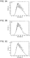
- the reflection spectrum for each half is presented in FIGS. 3A and 3B , and the combined spectrum reflected from both samples is shown in FIG. 3C .
- the combined spectral graph received from a single white beam does not allow the discrimination of the signals arriving from each half, since we work under non-imaging conditions.
- FIGS. 3A and 3B it is apparent that the sinusoidal shapes in both graphs have a quasi-periodical appearance.
- the sensing process may affect both the refractive index and the absorption coefficient of the sensing layer.
- Measurements, calibration and analysis of data were performed according to the following sequence: As a first step for each set of measurements, the reflected reference spectrum (measured in dry nitrogen only) was subtracted from all the measured spectra. In the next step, the x-coordinate of reflected spectra was inverted from wavelength (nm) to wavenumbers (nm -1 ) and a linear interpolation was applied in order to obtain an evenly spaced new x-axis. Finally a FFT algorithm was applied. Each porous silicon section produces a characteristic peak in the Fourier domain. The position of the peak depends on the porous layer properties, and therefore is unique for each set of fringes.
- the experimental procedure was as follows. All samples were prepared using p-type doped Si substrates, 405-645 ⁇ m thick with a resistivity of 0.01-0.02 ⁇ -cm and (100) crystal orientation. The silicon wafer was diced into 1 cm 2 chips, and each chip was electrochemically etched using an electrolyte solution containing 30% HF (48% aqueous) and 70% ethanol. Porous layers of 3 and 5 ⁇ m were etched with a current density of 50mA/cm 2 for 86s and 143s respectively. Immediately after etching, each chip was rinsed with ethanol and then with pentane.
- Indicator solutions were prepared by dissolving 100 mg pH indicator dye Bromotymol blue (BTB) in 30 mL ethanol. A volume of 15 ⁇ L dye solution was deposited on the surface of one sample, and the sample was left to dry for 24 hours.
- BTB Bromotymol blue
- Thermal oxidation was carried out in air on another sample at 300°C for 30 min, and then heated further to 900°C for another 30 min.
- Thermal preoxidation at 300°C is known to have a stabilizing effect on PSi by hindering the fragile texture of the material from collapsing during further treatments at higher temperatures.
- Thermal oxidation increases the hydrophilicity of the porous layer, allowing water vapor to effectively infiltrate the pores.
- the sensor was placed into a scaled flow cell with a quartz window to enable light illumination of the sensor.
- Light from a tungsten halogen lamp was transmitted through six 400 ⁇ m fibers and used as the illumination source. Reflected light was collected by a fiber located in the middle of the bundle.
- a special beam arrangement was constructed employing a cube beam-splitter and a prism (not shown), making it possible to observe the combined spectrum, as well as each separate spectrum by covering one of the beams.
- This setup was used for experimental evaluation only.
- a practical device preferably employs a single white-light beam and measures the combined reflected light. The reflection spectrum was measured over a spectral range 500-1000nm, using a compact spectrometer.
- the splitter/prism arrangement was designed to allow separate measurement for each section and for their combination. For the purpose of the experiment, this allowed verification that the spectral information from the separated sections can successfully be retrieved from the combined spectrum.
- FIGS. 4A and 4B show that the porous silicon with immobilized pH indicator shows both absorption and a slight sinusoidal shift towards longer wavelengths as a result of addition dry ammonia. This response is also non-linear.
- FIG. 4B shows that the oxidized porous silicon is inert to dry ammonia. Dry ammonia certainly penetrates the pores, but it doesn't change significantly the effective refractive index of PSi, since the refractive index of gaseous ammonia is similar to that of air. Furthermore the results here were recorded at very low NH 3 concentrations. We conclude therefore that oxidized PSi without pH indicator is not affected by ammonia at low concentrations. This conclusion is also supported by the resolved Fourier analysis shown below.
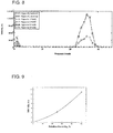
- FIG. 6 presents variations in the spectral response of the porous structures to pure water vapor. Specifically, measurements were performed at 33%, 67% and 100% relative humidity, at room temperature (25°C). All spectra were normalized with respect to that of dry nitrogen, while the total flow rate was kept constant at 150 standard cubic centimeters per minute (sccm).
- FIG. 6 shows the FFT of the combined normalized spectra, exhibiting two peaks, one corresponding to dye immobilized PSi and the other to oxidized PSi. As seen, the peak resulting from the oxidized PSi displays more significant changes, because of its hydrophilicity as compared to the non-oxidized PSi.
- the intensity of the peak increases with relative humidity level. Without in any way limiting the present invention, this is believed to be due to the fact that the spectrum on which FFT is applied is not an absolute spectrum but a normalized spectrum. Therefore, slight changes in periodicity appear as peaks in the FFT graph. The more water vapor infiltrates the pores, the bigger the red shift, the bigger the amplitude of the normalized spectrum and therefore the higher the peak.
- the sensitivity was mainly limited by the light source long term instability which may be improved by better current stabilization. Further improvement may be achieved by using a more sensitive indicator dye or by optimizing the concentration and the sensitization method.
Landscapes
- Chemical & Material Sciences (AREA)
- Health & Medical Sciences (AREA)
- Engineering & Computer Science (AREA)
- Physics & Mathematics (AREA)
- Life Sciences & Earth Sciences (AREA)
- Pathology (AREA)
- Analytical Chemistry (AREA)
- Biochemistry (AREA)
- General Health & Medical Sciences (AREA)
- General Physics & Mathematics (AREA)
- Immunology (AREA)
- Plasma & Fusion (AREA)
- Chemical Kinetics & Catalysis (AREA)
- Combustion & Propulsion (AREA)
- Food Science & Technology (AREA)
- Medicinal Chemistry (AREA)
- Investigating Or Analysing Materials By Optical Means (AREA)
- Investigating Or Analysing Materials By The Use Of Chemical Reactions (AREA)
Claims (11)
- System zum optischen Abtasten von Substanzen oder Umgebungsbedingungen in einem Fluid, wobei das System Folgendes umfasst:a) eine Sensorvorrichtung (10), die Folgendes umfasst:eine Vielzahl von nicht überlappenden benachbarten Sensorelementen (12), die in einem Array (24) angeordnet sind, wobei jedes der Sensorelemente (12) ein geschichtetes optisches Element zum Generieren eines wellenlängenspezifischen Interferenzeffekts umfasst, wobei jedes der geschichteten optischen Elemente mit einem Indikator verknüpft ist, um auf das Vorliegen einer vordefinierten Substanz oder einer vordefinierten Umgebungsbedingung anzusprechen, um eine optisch erkennbare Änderung zu verursachen, wobei sich die Sensorelemente sowohl durch den wellenlängenspezifischen Interferenzeffekt als auch durch die optisch erkennbare Änderung voneinander unterscheiden;b) eine Beleuchtungsanordnung, die einen gemeinsamen Multiwellenlängen-Beleuchtungsstrahl gleichzeitig auf alle Sensorelemente (12) richtet; undc) eine Spektralanalyseanordnung, die eine Empfängeroptik (20) umfasst, die aufgestellt wird, um Licht, das von der Vielzahl von Sensorelementen (12) reflektiert oder durch diese durchgelassen wird, zu kombinieren, und um das kombinierte Licht ohne Bildgebung in ein Spektrometer zu leiten,wobei die Spektralanalyseanordnung konfiguriert ist, um Daten zu verarbeiten, die von dem Spektrometer durch Spektralanalyse abgetastet werden, um Spektralmerkmale zu identifizieren, die jedem Sensorelement entsprechen, und um Änderungen dieser Spektralmerkmale zu detektieren, die den Zustand des Indikators jedes Sensorelements angeben, wodurch eine gleichzeitige Abtastung einer Vielzahl von Substanzen oder Umgebungsbedingungen erreicht wird.
- System nach Anspruch 1, wobei das geschichtete optische Element mindestens eine Schicht von porösem Silizium umfasst.
- System nach Anspruch 2, wobei sich die Sensorelemente durch die Dicke der mindestens einen Schicht von porösem Silizium unterscheiden.
- System nach Anspruch 2, wobei mindestens eines der Sensorelemente in der mindestens einen Schicht von porösem Silizium oxidierte Oberflächen aufweist.
- System nach einem der vorhergehenden Ansprüche, wobei der Indikator mindestens eines der Sensorelemente (12) ein temperaturreaktives Material oder ein druckreaktives Material umfasst.
- System nach einem der vorhergehenden Ansprüche, wobei der Indikator mindestens eines der Sensorelemente (12) auf das Vorliegen der vordefinierten Substanz oder der vordefinierten Umgebungsbedingung reagiert, um Folgendes zu erfahren: eine Änderung des Absorptionsspektrums; eine Änderung des Brechungsindex; oder eine Änderung der Dimensionen.
- System nach einem der vorhergehenden Ansprüche, wobei der Indikator mindestens eines der Sensorelemente (12) mindestens ein Element der Gruppe umfasst, die aus: pH-empfindlichen Farbstoffen, Porphyrinen, Metallporphyrinen, Proteinen, Antikörpern und DNA besteht.
- System nach einem der vorhergehenden Ansprüche, wobei die Vielzahl von Sensorelementen (12) mindestens drei Sensorelemente umfasst.
- System nach einem der vorhergehenden Ansprüche, ferner umfassend ein Referenzelement, das in einer nicht überlappenden Beziehung benachbart zu der Vielzahl von Sensorelementen angeordnet ist, wobei die Referenzelemente ein geschichtetes optisches Element zum Generieren eines wellenlängenspezifischen Interferenzeffekts, der anders als der wellenlängenspezifische Interferenzeffekt jedes der Sensorelemente ist, umfasst, wobei das Referenzelement ohne Indikator bereitgestellt wird, um eine Kalibrierungsreferenz bereitzustellen, wenn es zusammen mit den Sensorelementen beleuchtet wird.
- System nach einem der vorhergehenden Ansprüche, wobei die Vielzahl von Sensorelementen (12) in einen gemeinsamen Halbleiter-Chip integriert ist.
- Verfahren zum Abtasten von Substanzen oder Umgebungsbedingungen in einem Fluid, umfassend folgende Schritte:a) Bereitstellen einer Vorrichtung (10), die eine Vielzahl von nicht überlappenden benachbarten Sensorelementen (12) umfasst, wobei jedes der Sensorelemente (12) ein geschichtetes optisches Element umfasst, das konfiguriert ist, um einen wellenlängenspezifischen Interferenzeffekt zu generieren, wobei jedes der geschichteten optischen Elemente mit einem Indikator verknüpft ist, um auf das Vorliegen einer vordefinierten Substanz oder einer vordefinierten Umgebungsbedingung anzusprechen, um eine optisch erkennbare Änderung zu verursachen, wobei sich die Sensorelemente sowohl durch den wellenlängenspezifischen Interferenzeffekt als auch durch die optisch erkennbare Änderung voneinander unterscheiden;b) Verwenden eine Beleuchtungsanordnung, um einen gemeinsamen Multiwellenlängen-Beleuchtungsstrahl gleichzeitig auf alle Sensorelemente (12) zu richten; undc) Kombinieren von Licht, das von der Vielzahl von Sensorelementen (12) reflektiert oder durch diese durchgelassen wird, und Leiten des kombinierten Lichts ohne Bildgebung in ein Spektrometer, undd) Verarbeiten von Daten, die von dem Spektrometer abgetastet werden, durch Spektralanalyse, um die Spektralmerkmale zu identifizieren, die jedem Sensorelement entsprechen, und um Änderungen dieser Spektralmerkmale zu erkennen, die den Zustand des Indikators jedes Sensorelements angeben, wodurch das gleichzeitige Abtasten einer Vielzahl von Substanzen oder Umgebungsbedingungen erreicht wird.
Applications Claiming Priority (2)
| Application Number | Priority Date | Filing Date | Title |
|---|---|---|---|
| US16035709P | 2009-03-16 | 2009-03-16 | |
| PCT/IB2010/051131 WO2010106493A1 (en) | 2009-03-16 | 2010-03-16 | Device and method for optical sensing of substances or environmental conditions |
Publications (2)
| Publication Number | Publication Date |
|---|---|
| EP2409136A1 EP2409136A1 (de) | 2012-01-25 |
| EP2409136B1 true EP2409136B1 (de) | 2017-05-17 |
Family
ID=42227704
Family Applications (1)
| Application Number | Title | Priority Date | Filing Date |
|---|---|---|---|
| EP10712785.4A Not-in-force EP2409136B1 (de) | 2009-03-16 | 2010-03-16 | Vorrichtung und verfahren zur optischen erfassung von stoffen oder umweltbedingungen |
Country Status (4)
| Country | Link |
|---|---|
| US (1) | US9013707B2 (de) |
| EP (1) | EP2409136B1 (de) |
| CN (1) | CN102317760B (de) |
| WO (1) | WO2010106493A1 (de) |
Families Citing this family (10)
| Publication number | Priority date | Publication date | Assignee | Title |
|---|---|---|---|---|
| JP6051294B2 (ja) * | 2012-04-27 | 2016-12-27 | イー・アイ・デュポン・ドウ・ヌムール・アンド・カンパニーE.I.Du Pont De Nemours And Company | 光保護材料を決定するためのデバイス |
| CA2897181A1 (en) * | 2013-01-11 | 2014-07-17 | Lumense, Inc. | System and method for sensing ammonia in a fluid |
| CN103398992A (zh) * | 2013-08-09 | 2013-11-20 | 中山欧麦克仪器设备有限公司 | 一种新型的高精度荧光法溶解氧检测仪 |
| CN103398991A (zh) * | 2013-08-09 | 2013-11-20 | 中山欧麦克仪器设备有限公司 | 一种新型的双通道荧光法溶解氧检测仪 |
| CN103581391B (zh) * | 2013-11-22 | 2017-02-22 | 武汉友芝友医疗科技股份有限公司 | 用于测量体液酸碱度的智能手机及体液酸碱度测量方法 |
| GB201403391D0 (en) * | 2014-02-26 | 2014-04-09 | Protein Technologies Ltd | A method and device for monitoring substances |
| GB2525854B (en) | 2014-05-02 | 2019-08-07 | Sensorhut Ltd | Sensing methods and apparatus |
| EP3224595A4 (de) * | 2014-09-24 | 2018-06-13 | Good Start Genetics, Inc. | Prozesssteuerung für erhöhte robustheit von genetischen assays |
| EP3522556B1 (de) | 2018-02-05 | 2022-03-30 | Sartorius Stedim Biotech GmbH | Sensorelement und drahtloskommunikationsvorrichtung für elemente zur einmaligen verwendung |
| GB202102889D0 (en) * | 2021-03-01 | 2021-04-14 | Univ Nottingham | Fibre optic chemical sensing |
Citations (1)
| Publication number | Priority date | Publication date | Assignee | Title |
|---|---|---|---|---|
| WO1999012035A1 (en) * | 1997-09-05 | 1999-03-11 | The Scripps Research Institute | A porous semiconductor-based optical interferometric sensor |
Family Cites Families (9)
| Publication number | Priority date | Publication date | Assignee | Title |
|---|---|---|---|---|
| US4526753A (en) * | 1983-07-06 | 1985-07-02 | Miles Laboratories, Inc. | Multiple profile reagent card |
| DE4431412C1 (de) * | 1994-08-24 | 1996-03-14 | William Newton | Vorrichtung zur Durchführung spektroskopischer Messungen |
| US5929990A (en) * | 1997-03-19 | 1999-07-27 | Litton Systems, Inc. | Fabry-perot pressure sensing system with ratioed quadrature pulse detection |
| US7390461B2 (en) * | 2002-05-14 | 2008-06-24 | Arryx, Inc. | Broad spectrum optically addressed sensor |
| IE20030144A1 (en) * | 2003-02-28 | 2004-09-08 | Univ Dublin City | Improved optical sensors |
| US7394547B2 (en) * | 2003-11-06 | 2008-07-01 | Fortebio, Inc. | Fiber-optic assay apparatus based on phase-shift interferometry |
| US7466409B2 (en) * | 2005-06-08 | 2008-12-16 | California Institute Of Technology | Method and apparatus for CMOS imagers and spectroscopy |
| US7433552B2 (en) * | 2005-12-22 | 2008-10-07 | Palo Alto Research Center Incorporated | Obtaining analyte information |
| CN101378067B (zh) * | 2007-08-31 | 2010-09-29 | 邵剑心 | 特征光谱识别芯片、其制造方法及使用该芯片的检测装置 |
-
2010
- 2010-03-16 EP EP10712785.4A patent/EP2409136B1/de not_active Not-in-force
- 2010-03-16 CN CN201080012259.8A patent/CN102317760B/zh not_active Expired - Fee Related
- 2010-03-16 WO PCT/IB2010/051131 patent/WO2010106493A1/en not_active Ceased
-
2011
- 2011-09-15 US US13/233,158 patent/US9013707B2/en not_active Expired - Fee Related
Patent Citations (1)
| Publication number | Priority date | Publication date | Assignee | Title |
|---|---|---|---|---|
| WO1999012035A1 (en) * | 1997-09-05 | 1999-03-11 | The Scripps Research Institute | A porous semiconductor-based optical interferometric sensor |
Also Published As
| Publication number | Publication date |
|---|---|
| WO2010106493A1 (en) | 2010-09-23 |
| EP2409136A1 (de) | 2012-01-25 |
| CN102317760A (zh) | 2012-01-11 |
| US9013707B2 (en) | 2015-04-21 |
| CN102317760B (zh) | 2014-10-22 |
| US20120013911A1 (en) | 2012-01-19 |
Similar Documents
| Publication | Publication Date | Title |
|---|---|---|
| EP2409136B1 (de) | Vorrichtung und verfahren zur optischen erfassung von stoffen oder umweltbedingungen | |
| US6686201B2 (en) | Chemically-resistant sensor devices, and systems and methods for using same | |
| US11187652B2 (en) | Method and spectrometer apparatus for investigating an infrared absorption of a sample | |
| Gao et al. | Porous-silicon vapor sensor based on laser interferometry | |
| EP3137880B1 (de) | Messverfahren und -vorrichtung | |
| US8729502B1 (en) | Simultaneous, single-detector fluorescence detection of multiple analytes with frequency-specific lock-in detection | |
| Choi et al. | Humidity-sensitive optode membrane based on a fluorescent dye immobilized in gelatin film | |
| US8988688B2 (en) | Optical sensing devices and methods for detecting samples using the same | |
| Anderson et al. | Sensitivity of the optical properties of porous silicon layers to the refractive index of liquid in the pores | |
| US20030146109A1 (en) | Porous thin film time-varying reflectivity analysis of samples | |
| Lova et al. | Flory–Huggins photonic sensors for the optical assessment of molecular diffusion coefficients in polymers | |
| US10309958B2 (en) | Method and apparatus for bacterial monitoring | |
| JPH06508694A (ja) | ファイバー光センサー、装置、及び流体または蒸気サンプル中の有機分析物を検出するための方法 | |
| Chen et al. | Fluorescence-based optical sensor design for molecularly imprinted polymers | |
| Maciak et al. | An optical ammonia (NH3) gas sensing by means of Pd/CuPc interferometric nanostructures based on white light interferometry | |
| Volpati et al. | Toward the optimization of an e-tongue system using information visualization: a case study with perylene tetracarboxylic derivative films in the sensing units | |
| US7026165B2 (en) | Calibration-free optical chemical sensors | |
| Goustouridis et al. | Characterization of polymer layers for silicon micromachined bilayer chemical sensors using white light interferometry | |
| Ivanov et al. | Porous Bragg reflector based sensors: Ways to increase sensitivity | |
| Hutter et al. | Non-imaging optical method for multi-sensing of gases based on porous silicon | |
| Kittle et al. | Additive combination of spectra reflected from porous silicon and carbon/porous silicon rugate filters to improve vapor selectivity | |
| Nguyen et al. | Cascaded nano-porous silicon for high sensitive biosensing and functional group distinguishing by Mid-IR spectra | |
| Hutter et al. | Method for increasing reliability in gas detection based on indicator gradient in a sensor array | |
| US20210310946A1 (en) | System and Method of Measuring Contaminants in a Substantially Translucent Material, Such as Water | |
| CN206270244U (zh) | 用于化学和生物分析的光纤传感器 |
Legal Events
| Date | Code | Title | Description |
|---|---|---|---|
| PUAI | Public reference made under article 153(3) epc to a published international application that has entered the european phase |
Free format text: ORIGINAL CODE: 0009012 |
|
| 17P | Request for examination filed |
Effective date: 20111006 |
|
| AK | Designated contracting states |
Kind code of ref document: A1 Designated state(s): AT BE BG CH CY CZ DE DK EE ES FI FR GB GR HR HU IE IS IT LI LT LU LV MC MK MT NL NO PL PT RO SE SI SK SM TR |
|
| DAX | Request for extension of the european patent (deleted) | ||
| 17Q | First examination report despatched |
Effective date: 20140911 |
|
| GRAP | Despatch of communication of intention to grant a patent |
Free format text: ORIGINAL CODE: EPIDOSNIGR1 |
|
| INTG | Intention to grant announced |
Effective date: 20161212 |
|
| GRAS | Grant fee paid |
Free format text: ORIGINAL CODE: EPIDOSNIGR3 |
|
| GRAA | (expected) grant |
Free format text: ORIGINAL CODE: 0009210 |
|
| AK | Designated contracting states |
Kind code of ref document: B1 Designated state(s): AT BE BG CH CY CZ DE DK EE ES FI FR GB GR HR HU IE IS IT LI LT LU LV MC MK MT NL NO PL PT RO SE SI SK SM TR |
|
| REG | Reference to a national code |
Ref country code: GB Ref legal event code: FG4D |
|
| REG | Reference to a national code |
Ref country code: CH Ref legal event code: EP |
|
| REG | Reference to a national code |
Ref country code: IE Ref legal event code: FG4D |
|
| REG | Reference to a national code |
Ref country code: AT Ref legal event code: REF Ref document number: 894910 Country of ref document: AT Kind code of ref document: T Effective date: 20170615 |
|
| REG | Reference to a national code |
Ref country code: DE Ref legal event code: R096 Ref document number: 602010042395 Country of ref document: DE |
|
| REG | Reference to a national code |
Ref country code: NL Ref legal event code: MP Effective date: 20170517 |
|
| REG | Reference to a national code |
Ref country code: LT Ref legal event code: MG4D |
|
| REG | Reference to a national code |
Ref country code: AT Ref legal event code: MK05 Ref document number: 894910 Country of ref document: AT Kind code of ref document: T Effective date: 20170517 |
|
| PG25 | Lapsed in a contracting state [announced via postgrant information from national office to epo] |
Ref country code: FI Free format text: LAPSE BECAUSE OF FAILURE TO SUBMIT A TRANSLATION OF THE DESCRIPTION OR TO PAY THE FEE WITHIN THE PRESCRIBED TIME-LIMIT Effective date: 20170517 Ref country code: GR Free format text: LAPSE BECAUSE OF FAILURE TO SUBMIT A TRANSLATION OF THE DESCRIPTION OR TO PAY THE FEE WITHIN THE PRESCRIBED TIME-LIMIT Effective date: 20170818 Ref country code: AT Free format text: LAPSE BECAUSE OF FAILURE TO SUBMIT A TRANSLATION OF THE DESCRIPTION OR TO PAY THE FEE WITHIN THE PRESCRIBED TIME-LIMIT Effective date: 20170517 Ref country code: HR Free format text: LAPSE BECAUSE OF FAILURE TO SUBMIT A TRANSLATION OF THE DESCRIPTION OR TO PAY THE FEE WITHIN THE PRESCRIBED TIME-LIMIT Effective date: 20170517 Ref country code: NO Free format text: LAPSE BECAUSE OF FAILURE TO SUBMIT A TRANSLATION OF THE DESCRIPTION OR TO PAY THE FEE WITHIN THE PRESCRIBED TIME-LIMIT Effective date: 20170817 Ref country code: LT Free format text: LAPSE BECAUSE OF FAILURE TO SUBMIT A TRANSLATION OF THE DESCRIPTION OR TO PAY THE FEE WITHIN THE PRESCRIBED TIME-LIMIT Effective date: 20170517 Ref country code: ES Free format text: LAPSE BECAUSE OF FAILURE TO SUBMIT A TRANSLATION OF THE DESCRIPTION OR TO PAY THE FEE WITHIN THE PRESCRIBED TIME-LIMIT Effective date: 20170517 |
|
| PG25 | Lapsed in a contracting state [announced via postgrant information from national office to epo] |
Ref country code: IS Free format text: LAPSE BECAUSE OF FAILURE TO SUBMIT A TRANSLATION OF THE DESCRIPTION OR TO PAY THE FEE WITHIN THE PRESCRIBED TIME-LIMIT Effective date: 20170917 Ref country code: NL Free format text: LAPSE BECAUSE OF FAILURE TO SUBMIT A TRANSLATION OF THE DESCRIPTION OR TO PAY THE FEE WITHIN THE PRESCRIBED TIME-LIMIT Effective date: 20170517 Ref country code: PL Free format text: LAPSE BECAUSE OF FAILURE TO SUBMIT A TRANSLATION OF THE DESCRIPTION OR TO PAY THE FEE WITHIN THE PRESCRIBED TIME-LIMIT Effective date: 20170517 Ref country code: SE Free format text: LAPSE BECAUSE OF FAILURE TO SUBMIT A TRANSLATION OF THE DESCRIPTION OR TO PAY THE FEE WITHIN THE PRESCRIBED TIME-LIMIT Effective date: 20170517 Ref country code: BG Free format text: LAPSE BECAUSE OF FAILURE TO SUBMIT A TRANSLATION OF THE DESCRIPTION OR TO PAY THE FEE WITHIN THE PRESCRIBED TIME-LIMIT Effective date: 20170817 Ref country code: LV Free format text: LAPSE BECAUSE OF FAILURE TO SUBMIT A TRANSLATION OF THE DESCRIPTION OR TO PAY THE FEE WITHIN THE PRESCRIBED TIME-LIMIT Effective date: 20170517 |
|
| PG25 | Lapsed in a contracting state [announced via postgrant information from national office to epo] |
Ref country code: SK Free format text: LAPSE BECAUSE OF FAILURE TO SUBMIT A TRANSLATION OF THE DESCRIPTION OR TO PAY THE FEE WITHIN THE PRESCRIBED TIME-LIMIT Effective date: 20170517 Ref country code: RO Free format text: LAPSE BECAUSE OF FAILURE TO SUBMIT A TRANSLATION OF THE DESCRIPTION OR TO PAY THE FEE WITHIN THE PRESCRIBED TIME-LIMIT Effective date: 20170517 Ref country code: EE Free format text: LAPSE BECAUSE OF FAILURE TO SUBMIT A TRANSLATION OF THE DESCRIPTION OR TO PAY THE FEE WITHIN THE PRESCRIBED TIME-LIMIT Effective date: 20170517 Ref country code: CZ Free format text: LAPSE BECAUSE OF FAILURE TO SUBMIT A TRANSLATION OF THE DESCRIPTION OR TO PAY THE FEE WITHIN THE PRESCRIBED TIME-LIMIT Effective date: 20170517 Ref country code: DK Free format text: LAPSE BECAUSE OF FAILURE TO SUBMIT A TRANSLATION OF THE DESCRIPTION OR TO PAY THE FEE WITHIN THE PRESCRIBED TIME-LIMIT Effective date: 20170517 |
|
| REG | Reference to a national code |
Ref country code: DE Ref legal event code: R097 Ref document number: 602010042395 Country of ref document: DE |
|
| PG25 | Lapsed in a contracting state [announced via postgrant information from national office to epo] |
Ref country code: IT Free format text: LAPSE BECAUSE OF FAILURE TO SUBMIT A TRANSLATION OF THE DESCRIPTION OR TO PAY THE FEE WITHIN THE PRESCRIBED TIME-LIMIT Effective date: 20170517 Ref country code: SM Free format text: LAPSE BECAUSE OF FAILURE TO SUBMIT A TRANSLATION OF THE DESCRIPTION OR TO PAY THE FEE WITHIN THE PRESCRIBED TIME-LIMIT Effective date: 20170517 |
|
| PLBE | No opposition filed within time limit |
Free format text: ORIGINAL CODE: 0009261 |
|
| STAA | Information on the status of an ep patent application or granted ep patent |
Free format text: STATUS: NO OPPOSITION FILED WITHIN TIME LIMIT |
|
| REG | Reference to a national code |
Ref country code: FR Ref legal event code: PLFP Year of fee payment: 9 |
|
| 26N | No opposition filed |
Effective date: 20180220 |
|
| PG25 | Lapsed in a contracting state [announced via postgrant information from national office to epo] |
Ref country code: SI Free format text: LAPSE BECAUSE OF FAILURE TO SUBMIT A TRANSLATION OF THE DESCRIPTION OR TO PAY THE FEE WITHIN THE PRESCRIBED TIME-LIMIT Effective date: 20170517 |
|
| REG | Reference to a national code |
Ref country code: CH Ref legal event code: PL |
|
| PG25 | Lapsed in a contracting state [announced via postgrant information from national office to epo] |
Ref country code: MC Free format text: LAPSE BECAUSE OF FAILURE TO SUBMIT A TRANSLATION OF THE DESCRIPTION OR TO PAY THE FEE WITHIN THE PRESCRIBED TIME-LIMIT Effective date: 20170517 |
|
| REG | Reference to a national code |
Ref country code: BE Ref legal event code: MM Effective date: 20180331 |
|
| REG | Reference to a national code |
Ref country code: IE Ref legal event code: MM4A |
|
| PG25 | Lapsed in a contracting state [announced via postgrant information from national office to epo] |
Ref country code: LU Free format text: LAPSE BECAUSE OF NON-PAYMENT OF DUE FEES Effective date: 20180316 |
|
| PG25 | Lapsed in a contracting state [announced via postgrant information from national office to epo] |
Ref country code: IE Free format text: LAPSE BECAUSE OF NON-PAYMENT OF DUE FEES Effective date: 20180316 |
|
| PG25 | Lapsed in a contracting state [announced via postgrant information from national office to epo] |
Ref country code: LI Free format text: LAPSE BECAUSE OF NON-PAYMENT OF DUE FEES Effective date: 20180331 Ref country code: BE Free format text: LAPSE BECAUSE OF NON-PAYMENT OF DUE FEES Effective date: 20180331 Ref country code: CH Free format text: LAPSE BECAUSE OF NON-PAYMENT OF DUE FEES Effective date: 20180331 |
|
| PGFP | Annual fee paid to national office [announced via postgrant information from national office to epo] |
Ref country code: DE Payment date: 20190321 Year of fee payment: 10 Ref country code: FR Payment date: 20190322 Year of fee payment: 10 Ref country code: GB Payment date: 20190320 Year of fee payment: 10 |
|
| PG25 | Lapsed in a contracting state [announced via postgrant information from national office to epo] |
Ref country code: MT Free format text: LAPSE BECAUSE OF NON-PAYMENT OF DUE FEES Effective date: 20180316 |
|
| PG25 | Lapsed in a contracting state [announced via postgrant information from national office to epo] |
Ref country code: TR Free format text: LAPSE BECAUSE OF FAILURE TO SUBMIT A TRANSLATION OF THE DESCRIPTION OR TO PAY THE FEE WITHIN THE PRESCRIBED TIME-LIMIT Effective date: 20170517 |
|
| PG25 | Lapsed in a contracting state [announced via postgrant information from national office to epo] |
Ref country code: HU Free format text: LAPSE BECAUSE OF FAILURE TO SUBMIT A TRANSLATION OF THE DESCRIPTION OR TO PAY THE FEE WITHIN THE PRESCRIBED TIME-LIMIT; INVALID AB INITIO Effective date: 20100316 Ref country code: PT Free format text: LAPSE BECAUSE OF FAILURE TO SUBMIT A TRANSLATION OF THE DESCRIPTION OR TO PAY THE FEE WITHIN THE PRESCRIBED TIME-LIMIT Effective date: 20170517 |
|
| PG25 | Lapsed in a contracting state [announced via postgrant information from national office to epo] |
Ref country code: MK Free format text: LAPSE BECAUSE OF NON-PAYMENT OF DUE FEES Effective date: 20170517 Ref country code: CY Free format text: LAPSE BECAUSE OF FAILURE TO SUBMIT A TRANSLATION OF THE DESCRIPTION OR TO PAY THE FEE WITHIN THE PRESCRIBED TIME-LIMIT Effective date: 20170517 |
|
| REG | Reference to a national code |
Ref country code: DE Ref legal event code: R119 Ref document number: 602010042395 Country of ref document: DE |
|
| PG25 | Lapsed in a contracting state [announced via postgrant information from national office to epo] |
Ref country code: DE Free format text: LAPSE BECAUSE OF NON-PAYMENT OF DUE FEES Effective date: 20201001 Ref country code: FR Free format text: LAPSE BECAUSE OF NON-PAYMENT OF DUE FEES Effective date: 20200331 |
|
| GBPC | Gb: european patent ceased through non-payment of renewal fee |
Effective date: 20200316 |
|
| PG25 | Lapsed in a contracting state [announced via postgrant information from national office to epo] |
Ref country code: GB Free format text: LAPSE BECAUSE OF NON-PAYMENT OF DUE FEES Effective date: 20200316 |