EP2409047B1 - Wälzlagerkäfig mit führungsmitteln - Google Patents
Wälzlagerkäfig mit führungsmitteln Download PDFInfo
- Publication number
- EP2409047B1 EP2409047B1 EP10710299.8A EP10710299A EP2409047B1 EP 2409047 B1 EP2409047 B1 EP 2409047B1 EP 10710299 A EP10710299 A EP 10710299A EP 2409047 B1 EP2409047 B1 EP 2409047B1
- Authority
- EP
- European Patent Office
- Prior art keywords
- cage
- guide means
- recess
- shaped
- Prior art date
- Legal status (The legal status is an assumption and is not a legal conclusion. Google has not performed a legal analysis and makes no representation as to the accuracy of the status listed.)
- Not-in-force
Links
- 238000005096 rolling process Methods 0.000 title claims description 25
- 239000000463 material Substances 0.000 description 6
- 238000010276 construction Methods 0.000 description 5
- 238000004519 manufacturing process Methods 0.000 description 5
- 238000013016 damping Methods 0.000 description 3
- 230000002411 adverse Effects 0.000 description 1
- 230000000694 effects Effects 0.000 description 1
- 238000002347 injection Methods 0.000 description 1
- 239000007924 injection Substances 0.000 description 1
- 239000000314 lubricant Substances 0.000 description 1
- 239000002184 metal Substances 0.000 description 1
- 238000000465 moulding Methods 0.000 description 1
Images

Classifications
-
- F—MECHANICAL ENGINEERING; LIGHTING; HEATING; WEAPONS; BLASTING
- F16—ENGINEERING ELEMENTS AND UNITS; GENERAL MEASURES FOR PRODUCING AND MAINTAINING EFFECTIVE FUNCTIONING OF MACHINES OR INSTALLATIONS; THERMAL INSULATION IN GENERAL
- F16C—SHAFTS; FLEXIBLE SHAFTS; ELEMENTS OR CRANKSHAFT MECHANISMS; ROTARY BODIES OTHER THAN GEARING ELEMENTS; BEARINGS
- F16C33/00—Parts of bearings; Special methods for making bearings or parts thereof
- F16C33/30—Parts of ball or roller bearings
- F16C33/46—Cages for rollers or needles
- F16C33/4605—Details of interaction of cage and race, e.g. retention or centring
-
- F—MECHANICAL ENGINEERING; LIGHTING; HEATING; WEAPONS; BLASTING
- F16—ENGINEERING ELEMENTS AND UNITS; GENERAL MEASURES FOR PRODUCING AND MAINTAINING EFFECTIVE FUNCTIONING OF MACHINES OR INSTALLATIONS; THERMAL INSULATION IN GENERAL
- F16C—SHAFTS; FLEXIBLE SHAFTS; ELEMENTS OR CRANKSHAFT MECHANISMS; ROTARY BODIES OTHER THAN GEARING ELEMENTS; BEARINGS
- F16C19/00—Bearings with rolling contact, for exclusively rotary movement
- F16C19/22—Bearings with rolling contact, for exclusively rotary movement with bearing rollers essentially of the same size in one or more circular rows, e.g. needle bearings
- F16C19/34—Bearings with rolling contact, for exclusively rotary movement with bearing rollers essentially of the same size in one or more circular rows, e.g. needle bearings for both radial and axial load
- F16C19/36—Bearings with rolling contact, for exclusively rotary movement with bearing rollers essentially of the same size in one or more circular rows, e.g. needle bearings for both radial and axial load with a single row of rollers
-
- F—MECHANICAL ENGINEERING; LIGHTING; HEATING; WEAPONS; BLASTING
- F16—ENGINEERING ELEMENTS AND UNITS; GENERAL MEASURES FOR PRODUCING AND MAINTAINING EFFECTIVE FUNCTIONING OF MACHINES OR INSTALLATIONS; THERMAL INSULATION IN GENERAL
- F16C—SHAFTS; FLEXIBLE SHAFTS; ELEMENTS OR CRANKSHAFT MECHANISMS; ROTARY BODIES OTHER THAN GEARING ELEMENTS; BEARINGS
- F16C33/00—Parts of bearings; Special methods for making bearings or parts thereof
- F16C33/30—Parts of ball or roller bearings
- F16C33/46—Cages for rollers or needles
- F16C33/4611—Cages for rollers or needles with hybrid structure, i.e. with parts made of distinct materials
-
- F—MECHANICAL ENGINEERING; LIGHTING; HEATING; WEAPONS; BLASTING
- F16—ENGINEERING ELEMENTS AND UNITS; GENERAL MEASURES FOR PRODUCING AND MAINTAINING EFFECTIVE FUNCTIONING OF MACHINES OR INSTALLATIONS; THERMAL INSULATION IN GENERAL
- F16C—SHAFTS; FLEXIBLE SHAFTS; ELEMENTS OR CRANKSHAFT MECHANISMS; ROTARY BODIES OTHER THAN GEARING ELEMENTS; BEARINGS
- F16C33/00—Parts of bearings; Special methods for making bearings or parts thereof
- F16C33/30—Parts of ball or roller bearings
- F16C33/46—Cages for rollers or needles
- F16C33/4617—Massive or moulded cages having cage pockets surrounding the rollers, e.g. machined window cages
- F16C33/4664—Massive or moulded cages having cage pockets surrounding the rollers, e.g. machined window cages with more than three parts, e.g. two end rings connected by individual stays
-
- F—MECHANICAL ENGINEERING; LIGHTING; HEATING; WEAPONS; BLASTING
- F16—ENGINEERING ELEMENTS AND UNITS; GENERAL MEASURES FOR PRODUCING AND MAINTAINING EFFECTIVE FUNCTIONING OF MACHINES OR INSTALLATIONS; THERMAL INSULATION IN GENERAL
- F16C—SHAFTS; FLEXIBLE SHAFTS; ELEMENTS OR CRANKSHAFT MECHANISMS; ROTARY BODIES OTHER THAN GEARING ELEMENTS; BEARINGS
- F16C2300/00—Application independent of particular apparatuses
- F16C2300/10—Application independent of particular apparatuses related to size
- F16C2300/14—Large applications, e.g. bearings having an inner diameter exceeding 500 mm
Definitions
- the present invention relates to a cage for a rolling bearing with pocket-shaped recesses for receiving rolling elements and at least one guide means, which contributes to the leadership of the cage and is detachably connected to the cage.
- Rolling bearings which are equipped with cages without appropriate guide means, tend to wear faster and greater noise and also require a complex designed cage guide in the rolling bearing surrounding adjacent construction.
- a cage segment for a cage of a rolling bearing is described. This has in the region of the pocket-shaped recesses for receiving rolling elements tongue-like guide means which are integrally connected to the cage segment.
- the guiding means serve among other things, as support elements in order to support the cage, for example in the case of a temperature-induced expansion, with respect to the raceway of an outer ring.
- the invention is based on the object to provide a cage of the generic type, which is inexpensive to produce and is improved in terms of the design of its guide elements.
- the cage should be suitable to influence its rotational resistance in the rolling bearing.
- the invention is therefore based on a cage for a roller bearing with pocket-shaped recesses for receiving rolling elements and at least one guide means, which contributes to the leadership of the cage and is releasably connected to the cage.
- at least one further recess for receiving the at least one guide means is present between at least two pocket-shaped recesses, that the at least one guide means has a body with an approximately rectangular, oblong shape in plan view, and that the body is provided with a recess within which at least one flexible component is arranged, which has an excess with respect to the pitch circle diameter of the rolling elements.
- the cage and the guide means can be manufactured separately, which facilitates the manufacture of both the cage and the guide means and reduces costs.
- the material of the guide means can be adapted to specific applications and be selected independently of the material of the cage.
- the approximately rectangular body of the guide means is provided with a recess, a desired weight saving is achieved by this on the one hand, and also serves this recess for receiving a flexible member, which has an excess in its positioning relative to the pitch circle diameter of the rolling elements ,
- a targeted adjustment of the rotational resistance or the damping properties by means of the inventively designed cage can be done by choosing appropriate materials. But it is also possible to accomplish such an adjustment by at least one integrated into the flexible member spring element.
- the guide means is clipped or latched to the cage. This makes it particularly easy to connect the guide means during its manufacture with the cage.
- Another embodiment provides that a plurality of further recesses for receiving guide means are arranged distributed uniformly on the circumference of the cage, wherein in each case a pocket-shaped recess and such a further recess are arranged alternately.
- the leadership of the cage can be optimized around its entire circumference, the design of the individual guide means must be designed less expensive than if only one guide means would be used.
- the guide means has a body with an approximately rectangular in plan shape, elongated shape.
- this approximately rectangular body of the guide means is provided on its side walls in each case with at least one Rastanformung.
- the approximately rectangular body of the guide means is provided with a groove which serves for at least partially receiving a part of the cage.
- the groove may advantageously be formed in the top view in approximately arcuate or hook-shaped.
- the approximately rectangular body of the guide means with at least one guide surface is provided, which is arranged in the mounting position of the guide means on the cage radially inward and aligned approximately parallel to the axial direction of the cage.
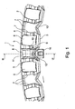
- FIG. 1 Referenced.
- an inventive bearing cage 1 which has an outer ring 2 and an inner ring 3.
- Outer ring 2 and inner ring 3 are connected to each other via webs 4, wherein the webs 4 are arranged uniformly spaced over the circumference of the bearing cage 1.
- pocket-like recesses 5 for receiving roller-shaped rolling elements 6 and on the other further recesses 7 for receiving guide means 8 are formed.
- the pocket-like recesses 5 and the further recesses 7 are arranged alternately distributed over the circumference. In the embodiment shown, however, only one recess 7 is equipped with a guide means 8.
- the webs 4 approximately have the shape of a depression with a plurality of stepped sections and a deepest, lower section 9.
- the guide means 8 shown is inserted from the bottom of the bearing cage 1 upwards into a recess 7 and by means of two locking elements 10, of which only one is visible, locked against the section 9 or clipped. It can be seen that the shape of the guide means 8 seen in plan view adapted approximately to the shape of the recess 7 and is formed approximately rectangular.
- the guide means 8 has a recess 11 approximately in the region between the two rings 2, 3 of the bearing cage 1. This recess 11 can serve, for example, for receiving a flexible component, what else in connection with Fig. 3 will be received.
- the guide means 8 is provided with a groove 12 which serves to receive a part 13 of the inner ring 3.
- This part 13 is hook-shaped or roof-shaped in plan view in the embodiment shown.
- other shapes are possible, for example, a curved shape.
- the illustrated shape increases both in the circumferential direction as well as in the radial direction the support of the guide means 8 on the bearing cage. 1
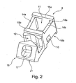
- FIG. 2 taken in which the guide means 8 is shown alone and in perspective in greatly enlarged view.
- the recess 11 which is bounded by two side walls 14a, 14b and two end walls 15a, 15b.
- On the outer surfaces of the side walls 14a, 14b are each the already mentioned locking element 10, wherein also here only one is recognizable due to the selected view.
- the groove 12 can be seen, into which the part 13 of the inner ring 3 of the bearing cage 1 engages in the mounting position of the guide means 8. Further, a radially inner end piece 16 is formed by the groove 12, which is provided with a in the mounting position of the guide means 8 radially inwardly facing trough 17. Furthermore, the end piece 16 has a guide surface 21, whose function will be explained later.
- the two side walls 14a and 14b each have a lower height than the two end walls 15a and 15b, whereby approximately rectangular recesses 18 are formed on the guide means 8.
- FIG. 3 shows a sectional view according to sectional view III-III in FIG. 1 , where in FIG. 3 additionally a connection construction with a radially inwardly disposed shaft 19 and with bearing rings 20 are shown. Furthermore, it can be seen that in the illustrated mounting position of the bearing cage 1 according to the invention the radially inner end piece 16 rests with the radially oriented guide surface 21 against a radial outer shoulder 22 of the Welle19 leader. The guide surface 21 is aligned approximately parallel to an axial direction A of the bearing cage.
- a flexible component 23 is shown, which is embedded in the already mentioned recess 11 of the guide means 8 and with respect to the pitch circle diameter of the rolling elements 6 has an excess.
- the flexible component 23 presses against the two bearing rings 20, which leads to an increase in the frictional torque or the damping.
- This effect can be adjusted by choosing different suitable materials. But it is also possible to accomplish this through the use of an additional spring element 24 which is disposed within the flexible member 23 and only indicated.
- the flexible member 23 may also be a felt impregnated with lubricant.
- the production of the guide means 8 in different ways possible. So this can be made of a plastic injection molded part or a machined hard tissue part or as a sheet metal molding.
Landscapes
- Engineering & Computer Science (AREA)
- General Engineering & Computer Science (AREA)
- Mechanical Engineering (AREA)
- Rolling Contact Bearings (AREA)
Description
- Die vorliegende Erfindung betrifft einen Käfig für ein Wälzlager mit taschenförmigen Ausnehmungen für die Aufnahme von Wälzkörpern sowie mit wenigstens einem Führungsmittel, welches zur Führung des Käfigs beiträgt und lösbar mit dem Käfig verbunden ist.
- Die Führung eines Käfigs in einem montierten Wälzlager ist in der Regel notwendig, um diesen während des Betriebs in seiner Funktionsposition exakt und zuverlässig zu den Laufringen des Wälzlagers beziehungsweise zu Teilen der Anschlusskonstruktion (beispielsweise eine Welle oder ein Gehäuse) zu positionieren. Dadurch wird eine exakte Positionierung der Wälzkörper und somit eine einwandfreie Funktion des Wälzlagers gewährleistet. Es sind je nach Anwendungsfall und Bauart des Wälzlagers bzw, dessen Käfigs ein oder auch mehrere Führungsmittel möglich.
- Wälzlager, die mit Käfigen ohne entsprechende Führungsmittel ausgestattet sind, neigen zum schnelleren Verschleiß sowie stärkeren Laufgeräuschen und erfordern überdies eine aufwendig gestaltete Käfigführung in der das Wälzlager umgebenden Anschlusskonstruktion.
- In der
DE 10 2006 022 951 A1 ist ein Käfigsegment für einen Käfig eines Wälzlagers beschrieben. Dieses weist im Bereich der taschenförmigen Ausnehmungen für die Aufnahme von Wälzkörpern zungenartige Führungsmittel auf, die einstückig mit dem Käfigsegment verbunden sind. Die Führungsmittel dienen unter anderem als Abstützelemente, um den Käfig, beispielsweise im Fall einer temperaturbedingten Ausdehnung, gegenüber der Laufbahn eines Außenrings abzustützen. - Das Vorsehen von Führungsmitteln an dem Käfig eines Wälzlagers erschwert jedoch dessen Fertigung und macht diesen aufwendig sowie teuer. Des Weiteren ist auch die Flexibilität hinsichtlich der Ausgestaltung der Führungsmittel eingeschränkt, da man beispielsweise hinsichtlich der Wahl des Werkstoffs bereits auf den Werkstoff des Käfig-Grundkörpers beschränkt ist.
- Aus der
DE 10 2007 009 811 A1 ist ein mehrteiliger Axialkäfig für ein Großwälzlager bekannt, wobei der Käfig aus mehreren Flachbandabschnitten zusammengesetzt ist, welche Freiräume zur Aufnahme von als gesonderte Bauteile hergestellte Käfigfester aufweisen. Diese Käfigfenster sind in alle Freiräume der Flachbandabschnitte eingeklipst und dienen selbst zur Aufnahme von jeweils einem Wälzkörper. Die Käfigfenster weisen an einer schmalen Stirnseite jeweils einen Führungsbord auf, mit dem der Käfig an einem benachbarten Lagerbauteil führbar ist. Die dadurch erzeugte große Anzahl der Führungsborde erscheint überdimensioniert, was nachteilig zu erhöhten Herstellkosten führt. - Einen dazu ähnlichen Aufbau weist der Käfig gemäß der
EP 0 457 020 A1 auf, bei dem die Käfigfenster jedoch axial wechselseitig in die Freiräume des Käfigs eingesetzt sind. - Der Erfindung liegt die Aufgabe zu Grunde, einen Käfig der gattungsgemäßen Art bereitzustellen, welcher kostengünstig herstellbar ist und hinsichtlich der Ausgestaltung seiner Führungselemente verbessert ist. Außerdem soll der Käfig dazu geeignet sein, seinen Drehwiderstand im Wälzlager zu beeinflussen.
- Die Erfindung geht daher aus von einem Käfig für ein Wälzlager mit taschenförmigen Ausnehmungen für die Aufnahme von Wälzkörpern sowie mit wenigstens einem Führungsmittel, welches zur Führung des Käfigs beiträgt und lösbar mit dem Käfig verbunden ist. Zur Lösung der gestellten Aufgabe ist vorgesehen, dass zwischen wenigstens zwei taschenförmigen Ausnehmungen wenigstens eine weitere Ausnehmung zur Aufnahme des wenigstens einen Führungsmittels vorhanden ist, dass das wenigstens eine Führungsmittel einen Körper mit einer im Grundriss in etwa rechteckigen, länglichen Form aufweist, und dass der Körper mit einer Ausnehmung versehen ist, innerhalb der wenigstens ein flexibles Bauteil angeordnet ist, welches gegenüber dem Wälzkreis-Durchmesser der Wälzkörper ein Übermaß aufweist.
- Somit steht eine einfache, kostengünstige sowie flexible Konstruktion für die Führung des Käfigs bereit, wobei verschiedenste Käfigformen und Käfigabmessungen realisierbar sind. Durch die Lösbarkeit des Führungsmittels können der Käfig und das Führungsmittel getrennt voneinander gefertigt werden, welches die Fertigung sowohl des Käfigs als auch des Führungsmittels erleichtert und die Kosten senkt. Überdies kann der Werkstoff des Führungsmittels an spezielle Anwendungsfälle angepasst und unabhängig vom Werkstoff des Käfigs ausgewählt werden.
- Dadurch, dass der in etwa rechteckige Körper des Führungsmittels mit einer Ausnehmung versehen ist, wird durch diese einerseits eine gewünschte Gewichtseinsparung erreicht, und außerdem dient diese Ausnehmung zur Aufnahme eines flexiblen Bauteils, welches bei seiner Positionierung gegenüber dem Wälzkreis-Durchmesser der Wälzkörper ein Übermaß aufweist. Durch diese baulichen Maßnahmen können besondere Anforderungen bezüglich der Dämpfung und des Drehwiderstandes eines mit dem erfindungsgemäßen Käfig ausgestatteten Wälzlagers erfüllt werden. Durch das Übermaß wird bewirkt, dass bei eingebautem Wälzlager ein Druck auf zumindest einer seiner Laufringe ausgeübt wird und damit eine Erhöhung des Reibmomentes einhergeht.
- Eine gezielte Einstellung des Drehwiderstandes beziehungsweise der Dämpfungseigenschaften mittels des erfindungsgemäß ausgebildeten Käfigs kann durch die Wahl entsprechender Werkstoffe erfolgen. Es ist aber auch möglich, eine solche Einstellung durch wenigstens ein in das flexible Bauteil integriertes Federelement zu bewerkstelligen.
- Gemäß einer vorteilhaften Weiterbildung ist vorgesehen, dass das Führungsmittel mit dem Käfig verklipst bzw. verrastet ist. Dadurch lässt sich das Führungsmittel bei dessen Herstellung besonders einfach mit dem Käfig verbinden.
- Eine andere Ausgestaltung sieht vor, dass mehrere weitere Ausnehmungen zur Aufnahme von Führungsmitteln gleichmäßig an dem Umfang des Käfigs verteilt angeordnet sind, wobei jeweils eine taschenförmige Ausnehmung und eine solche weitere Ausnehmung abwechselnd angeordnet sind. Hierdurch kann die Führung des Käfigs um seinen gesamten Umfang optimiert werden, wobei die Ausgestaltung der einzelnen Führungsmittel weniger aufwendig gestaltet werden muss, als wenn nur ein Führungsmittel eingesetzt würde.
- Es hat sich hinsichtlich der Führungseigenschaften, einer guten Herstellbarkeit sowie einer guten Montierbarkeit des Käfigs als vorteilhaft erwiesen, dass das Führungsmittel einen Körper mit einer im Grundriss in etwa rechteckigen, länglichen Form aufweist. Bevorzugt ist dieser in etwa rechteckige Körper des Führungsmittels an seinen Seitenwänden jeweils mit wenigstens einer Rastanformung versehen.
- Zur Verbesserung der Positionierung und Lagefixierung des Führungsmittels am Käfig kann vorgesehen sein, dass der in etwa rechteckige Körper des Führungsmittels mit einer Nut versehen ist, welche zur wenigstens teilweisen Aufnahme eines Teils des Käfigs dient. Dabei kann die Nut vorteilhaft in der Draufsicht in etwa bogenförmig oder hakenförmig ausgebildet sein.
- Insbesondere zur Führung des Käfigs auf einer Welle (Anschlusskonstruktion) ist es vorteilhaft, wenn der in etwa rechteckige Körper des Führungsmittels mit wenigstens einer Führungsfläche versehen ist, die in der Montageposition des Führungsmittels am Käfig radial innen liegend angeordnet und in etwa parallel zur Axialrichtung des Käfigs ausgerichtet ist.
-
- Figur 1
- eine perspektivische Ansicht eines erfindungsgemäßen Lagerkäfigs mit einem eingesetzten Führungsmittel, wobei nur ein Teil des Käfigs dargestellt ist,
- Figur 2
- eine perspektivische Darstellung eines Führungsmittels, und
- Figur 3
- einen Längsschnitt des auf einer Anschlusskonstruktion montierten Lagerkäfigs gemäß Schnittansicht III in
Figur1 , wobei die Anschlusskonstruktion inFigur1 nicht gezeigt ist. - Zunächst wird auf
Figur 1 Bezug genommen. Darin ist in einer axialen Teilansicht ein erfindungsgemäßer Lagerkäfig 1 ersichtlich, welcher einen Außenring 2 und einen Innenring 3 aufweist. Außenring 2 und Innenring 3 sind über Stege 4 miteinander verbunden, wobei die Stege 4 über den Umfang des Lagerkäfigs 1 gleichmäßig beabstandet angeordnet sind. Dadurch sind zum einen taschenartige Ausnehmungen 5 zur Aufnahme von rollenförmigen Wälzkörpern 6 und zum anderen weitere Ausnehmungen 7 zur Aufnahme von Führungsmitteln 8 gebildet. Die taschenartigen Ausnehmungen 5 und die weiteren Ausnehmungen 7 sind über den Umfang verteilt abwechselnd angeordnet. Im gezeigten Ausführungsbeispiel ist jedoch nur eine Ausnehmung 7 mit einem Führungsmittel 8 bestückt. - Die Stege 4 weisen in der dem Pfeil entsprechenden Umfangsrichtung betrachtet in etwa die Form einer Senke mit mehreren stufenförmigen Abschnitten und einem tiefsten, unten liegenden Abschnitt 9 auf.
- Das gezeigte Führungsmittel 8 ist von der Unterseite des Lagerkäfigs 1 nach oben in eine Ausnehmung 7 eingeschoben und mittels zweier Rastelemente 10, von denen nur eines sichtbar ist, gegen den Abschnitt 9 verrastet beziehungsweise verklipst. Es ist ersichtlich, dass die Form des Führungsmittels 8 im Grundriss gesehen in etwa an die Form der Ausnehmung 7 angepasst und in etwa rechteckig ausgebildet ist.
- Des Weiteren ist erkennbar, dass das Führungsmittel 8 in etwa im Bereich zwischen den beiden Ringen 2, 3 des Lagerkäfigs 1 eine Ausnehmung 11 aufweist. Diese Ausnehmung 11 kann beispielsweise zur Aufnahme eines flexiblen Bauteils dienen, worauf noch im Zusammenhang mit
Fig. 3 eingegangen wird. - Im Bereich des Innenrings 3 des Lagerkäfigs 1 ist das Führungsmittel 8 mit einer Nut 12 versehen, die zur Aufnahme eines Teils 13 des Innenrings 3 dient. Dieses Teil 13 ist im gezeigten Ausführungsbeispiel in der Draufsicht haken- bzw. dachförmig ausgebildet. Für das Teil 3 sind natürlich auch andere Formen möglich, beispielsweise eine gebogene Form. Die dargestellte Form erhöht sowohl in Umfangsrichtung wie auch in Radialrichtung den Halt des Führungsmittels 8 am Lagerkäfig 1.
- Nunmehr wird Bezug auf
Figur 2 genommen, in der das Führungsmittel 8 in Alleinstellung und perspektivisch in stark vergrößerter Ansicht dargestellt ist. Deutlich erkennbar ist die Ausnehmung 11, welche durch zwei Seitenwände 14a, 14b sowie zwei Stirnwände 15a, 15b begrenzt ist. An den Außenflächen der Seitenwände 14a, 14b befindet sich jeweils das bereits erwähnte Rastelement 10, wobei auch hier aufgrund der gewählten Ansicht nur eines erkennbar ist. - Von der radial inneren Stirnwand 15b radial nach innen ausgehend, ist die Nut 12 erkennbar, in die in der Montageposition des Führungsmittels 8 das Teil 13 des Innenrings 3 des Lagerkäfigs 1 eingreift. Ferner wird durch die Nut 12 ein radial innen liegendes Endstück 16 gebildet, welches mit einer in der Montageposition des Führungsmittels 8 radial nach innen weisenden Mulde 17 versehen ist. Ferner weist das Endstück 16 eine Führungsfläche 21 auf, deren Funktion später erläutert wird. Die beiden Seitenwände 14a und 14b weisen jeweils eine geringere Höhe auf als die beiden Stirnwände 15a und 15b, wodurch etwa rechteckförmige Ausnehmungen 18 am Führungsmittel 8 gebildet sind.
- Die
Figur 3 zeigt eine Schnittdarstellung gemäß Schnittansicht III-III inFigur 1 , wobei inFigur 3 zusätzlich noch eine Anschlusskonstruktion mit einer radial innen angeordneten Welle 19 sowie mit Lagerringen 20 dargestellt sind. Ferner ist ersichtlich, dass in der dargestellten Montageposition des erfindungsgemäßen Lagerkäfigs 1 das radial innen liegende Endstück 16 mit der radial ausgerichteten Führungsfläche 21 gegen einen radialen Außenabsatz 22 der Welle19 führend anliegt. Die Führungsfläche 21 ist dabei in etwa parallel zu einer Axialrichtung A des Lagerkäfigs ausgerichtet. - Des Weiteren ist ein flexibles Bauteil 23 dargestellt, welches in die schon erwähnte Ausnehmung 11 des Führungsmittels 8 eingelassen ist und gegenüber dem Wälzkreis-Durchmesser der Wälzkörper 6 ein Übermaß aufweist. Dadurch drückt im Montagezustand das flexible Bauteil 23 gegen die beiden Lagerringe 20, was zu einer Erhöhung des Reibmomentes beziehungsweise der Dämpfung führt. Dieser Effekt kann durch die Wahl unterschiedlicher, geeigneter Werkstoffe eingestellt werden. Es ist aber auch möglich, dies durch den Einsatz eines zusätzlichen Federelementes 24 zu bewerkstelligen, welches innerhalb des flexiblen Bauteils 23 angeordnet und lediglich angedeutet ist. Das flexible Bauteil 23 kann auch ein mit Schmierstoff getränkter Filz sein.
- Selbstverständlich ist auch die Herstellung des Führungsmittels 8 auf unterschiedliche Art und Weise möglich. So kann dieses ein Kunststoff-Spritzteil oder ein spanend gefertigtes Hartgewebeteil oder auch als Blech-Formteil hergestellt sein.
-
- 1
- Lagerkäfig
- 2
- Außenring
- 3
- Innenring
- 4
- Stege
- 5
- Taschenartige Ausnehmungen
- 6
- Wälzkörper
- 7
- Weitere Ausnehmungen
- 8
- Führungsmittel
- 9
- Tiefster, unten liegender Abschnitt der Stege
- 10
- Rastelement
- 11
- Ausnehmung
- 12
- Nut
- 13
- Teil vom Innenring 3
- 14a
- Seitenwand des Führungsmittels
- 14b
- Seitenwand des Führungsmittels
- 15a
- Stirnwand des Führungsmittels
- 15b
- Stirnwand des Führungsmittels
- 16
- Radial innen liegendes Endstück
- 17
- Mulde
- 18a
- Ausnehmungen
- 18b
- Ausnehmungen
- 19
- Welle
- 20
- Lagerringe
- 21
- Führungsfläche
- 22
- Radialer Außenabsatz der Welle 19
- 23
- Flexibles Bauteil
- 24
- Federelement
- A
- Axialrichtung des Lagerkäfigs
Claims (8)
- Käfig (1) für ein Wälzlager mit taschenförmigen Ausnehmungen (5) für die Aufnahme von Wälzkörpern (6) sowie mit wenigstens einem Führungsmittel (8), welches zur Führung des Käfigs (1) beiträgt und lösbar mit dem Käfig (1) verbunden ist, dadurch gekennzeichnet, dass zwischen wenigstens zwei taschenförmigen Ausnehmungen (5) wenigstens eine weitere Ausnehmung (7) zur Aufnahme des wenigstens einen Führungsmittels (8) vorhanden ist, dass das wenigstens eine Führungsmittel (8) einen Körper mit einer im Grundriss in etwa rechteckigen, länglichen Form aufweist, und dass der Körper mit einer Ausnehmung (11) versehen ist, innerhalb der wenigstens ein flexibles Bauteil (23) angeordnet ist, welches gegenüber dem Wälzkreis-Durchmesser der Wälzkörper (6) ein Übermaß aufweist.
- Käfig nach Anspruch 1, dadurch gekennzeichnet, dass das Führungsmittel (8) mit dem Käfig (1) verklipst ist.
- Käfig nach Anspruch 1 oder 2, dadurch gekennzeichnet, dass mehrere weitere Ausnehmungen (7) zur Aufnahme von Führungsmitteln (8) gleichmäßig um den Umfang des Käfigs (1) verteilt angeordnet sind, wobei jeweils eine taschenförmige Ausnehmung (5) und eine weitere Ausnehmung (7) abwechselnd angeordnet sind.
- Käfig nach einem der vorherigen Ansprüche, dadurch gekennzeichnet, dass der in etwa rechteckige Körper des Führungsmittels (8) an seinen Seitenwänden (14a, 14b) jeweils mit wenigstens einem Rastelement (10) versehen ist.
- Käfig nach einem der vorherigen Ansprüche, dadurch gekennzeichnet, dass in das flexible Bauteil (23) wenigstens ein Federelement (24) integriert ist.
- Käfig nach einem der vorherigen Ansprüche, dadurch gekennzeichnet, dass der in etwa rechteckige Körper des Führungsmittels (8) mit einer Nut (12) versehen ist, welche zur wenigstens teilweisen Aufnahme eines Teils (13) des Käfigs (1) dient.
- Käfig nach einem der vorherigen Ansprüche, dadurch gekennzeichnet, dass die Nut (12) in der Draufsicht in etwa bogen- oder hakenförmig ausgebildet ist.
- Käfig nach einem der vorherigen Ansprüche, dadurch gekennzeichnet, dass der in etwa rechteckige Körper des Führungsmittels (8) mit wenigstens einer Führungsfläche (21) versehen ist, die in der Montageposition des Führungsmittels (8) am Käfig (1) radial innen liegend angeordnet und in etwa parallel zur Axialrichtung (A) des Käfigs (1) ausgerichtet ist.
Applications Claiming Priority (2)
| Application Number | Priority Date | Filing Date | Title |
|---|---|---|---|
| DE102009014276A DE102009014276A1 (de) | 2009-03-20 | 2009-03-20 | Käfig für ein Wälzlager |
| PCT/EP2010/053629 WO2010106172A1 (de) | 2009-03-20 | 2010-03-19 | Wälzlagerkäfig mit führungsmitteln |
Publications (2)
| Publication Number | Publication Date |
|---|---|
| EP2409047A1 EP2409047A1 (de) | 2012-01-25 |
| EP2409047B1 true EP2409047B1 (de) | 2013-10-16 |
Family
ID=42377230
Family Applications (1)
| Application Number | Title | Priority Date | Filing Date |
|---|---|---|---|
| EP10710299.8A Not-in-force EP2409047B1 (de) | 2009-03-20 | 2010-03-19 | Wälzlagerkäfig mit führungsmitteln |
Country Status (4)
| Country | Link |
|---|---|
| US (1) | US8690451B2 (de) |
| EP (1) | EP2409047B1 (de) |
| DE (1) | DE102009014276A1 (de) |
| WO (1) | WO2010106172A1 (de) |
Families Citing this family (2)
| Publication number | Priority date | Publication date | Assignee | Title |
|---|---|---|---|---|
| JP6460672B2 (ja) * | 2013-09-18 | 2019-01-30 | キヤノン株式会社 | 膜の製造方法、光学部品の製造方法、回路基板の製造方法及び電子部品の製造方法 |
| FR3014155B1 (fr) * | 2013-11-29 | 2016-05-06 | Snecma | Cage de roulement avec un jonc peripherique d'amortissement de vibrations |
Family Cites Families (10)
| Publication number | Priority date | Publication date | Assignee | Title |
|---|---|---|---|---|
| NL235328A (de) * | 1958-01-22 | 1900-01-01 | ||
| US3785710A (en) * | 1972-10-30 | 1974-01-15 | Torrington Co | Separator insert for thrust bearings |
| US4413866A (en) * | 1982-06-08 | 1983-11-08 | Rotek Incorporated | Bearing assembly with wear pads |
| DE3902937C2 (de) * | 1989-02-01 | 1996-08-01 | Skf Gmbh | Changierlager |
| DE4015303A1 (de) * | 1990-05-12 | 1991-11-21 | Hoesch Ag | Kaefig fuer ein grosswaelzlager |
| DE4232433C2 (de) * | 1992-09-28 | 2000-05-11 | Skf Gmbh | Käfigführung für Wälzlager, insbesondere für Axial-Zylinderrollenlager |
| US5249872A (en) * | 1992-10-30 | 1993-10-05 | The Torrington Company | Spring loaded bearing retainer |
| DE102006022951A1 (de) | 2006-05-17 | 2007-11-22 | Schaeffler Kg | Käfigsegment für einen Käfig eines Wälzlagers |
| DE102007009811A1 (de) * | 2007-02-28 | 2008-09-04 | Schaeffler Kg | Mehrteiliger Axialkäfig für ein Großwälzlager |
| CN102007311B (zh) * | 2008-06-17 | 2013-12-11 | 株式会社捷太格特 | 圆柱滚子轴承 |
-
2009
- 2009-03-20 DE DE102009014276A patent/DE102009014276A1/de not_active Withdrawn
-
2010
- 2010-03-19 EP EP10710299.8A patent/EP2409047B1/de not_active Not-in-force
- 2010-03-19 WO PCT/EP2010/053629 patent/WO2010106172A1/de not_active Ceased
- 2010-03-19 US US13/254,717 patent/US8690451B2/en not_active Expired - Fee Related
Also Published As
| Publication number | Publication date |
|---|---|
| US8690451B2 (en) | 2014-04-08 |
| US20120002911A1 (en) | 2012-01-05 |
| EP2409047A1 (de) | 2012-01-25 |
| WO2010106172A1 (de) | 2010-09-23 |
| DE102009014276A1 (de) | 2010-09-23 |
Similar Documents
| Publication | Publication Date | Title |
|---|---|---|
| EP4212751B1 (de) | Lagerkäfig | |
| EP2959176B1 (de) | Wälzlagerkäfig mit rastmitteln und nadellager mit einem an einem käfig eingerasteten aussenring | |
| DE102006022951A1 (de) | Käfigsegment für einen Käfig eines Wälzlagers | |
| AT514070A4 (de) | Zahnradanordnung | |
| DE102007002359A1 (de) | Taschensegmentkäfig für ein Wälzkörperlager und Wälzkörperlager mit dem Taschensegmentkäfig | |
| EP3724526B1 (de) | Teleskopschiene | |
| DE102014106587A1 (de) | Wälzlager, insbesondere Vierpunktlager oder Doppelvierpunktslager für Windkraftanlagen | |
| DE102015209598B4 (de) | Planetenwälzgewindetrieb | |
| DE102007036113B4 (de) | Linearkugellager | |
| DE1575608C3 (de) | Wälzlager für Längsbewegungen | |
| EP3234400A1 (de) | Scheibenbremse für ein nutzfahrzeug | |
| DE202009004791U1 (de) | Zylindrischer Wälzkörper und Linearlager mit diesen zylindrischen Wälzkörpern | |
| DE102016207034A1 (de) | Käfigsegment eines Zylinderrollenlagers | |
| EP3810944B1 (de) | Axialwälzlager | |
| DE102014219705A1 (de) | Lagerring | |
| EP3344890B1 (de) | Scheibenbremse für ein nutzfahrzeug | |
| DE102008062913A1 (de) | Segmentkäfig | |
| EP2409047A1 (de) | Wälzlagerkäfig mit führungsmitteln | |
| EP2208900A1 (de) | Wälzlagereinheit | |
| DE102008016798A1 (de) | Wälzlager sowie Lenkgetriebe mit einem derartigen Wälzlager | |
| DE202008017091U1 (de) | Segmentkäfig | |
| DE2922625A1 (de) | Waelzlager fuer laengsbewegungen | |
| DE102019118055A1 (de) | Wälzlageranordnung | |
| EP2894048A1 (de) | Laufrolle insbesondere für Schiebetüren | |
| DE102006015478A1 (de) | Wälzlager in Form einer Dreh- oder Linearführung |
Legal Events
| Date | Code | Title | Description |
|---|---|---|---|
| PUAI | Public reference made under article 153(3) epc to a published international application that has entered the european phase |
Free format text: ORIGINAL CODE: 0009012 |
|
| 17P | Request for examination filed |
Effective date: 20111020 |
|
| AK | Designated contracting states |
Kind code of ref document: A1 Designated state(s): AT BE BG CH CY CZ DE DK EE ES FI FR GB GR HR HU IE IS IT LI LT LU LV MC MK MT NL NO PL PT RO SE SI SK SM TR |
|
| RAP1 | Party data changed (applicant data changed or rights of an application transferred) |
Owner name: SCHAEFFLER TECHNOLOGIES AG & CO. KG |
|
| DAX | Request for extension of the european patent (deleted) | ||
| 17Q | First examination report despatched |
Effective date: 20130304 |
|
| GRAP | Despatch of communication of intention to grant a patent |
Free format text: ORIGINAL CODE: EPIDOSNIGR1 |
|
| RIC1 | Information provided on ipc code assigned before grant |
Ipc: F16C 19/36 20060101ALI20130430BHEP Ipc: F16C 33/46 20060101AFI20130430BHEP |
|
| INTG | Intention to grant announced |
Effective date: 20130524 |
|
| GRAS | Grant fee paid |
Free format text: ORIGINAL CODE: EPIDOSNIGR3 |
|
| GRAA | (expected) grant |
Free format text: ORIGINAL CODE: 0009210 |
|
| AK | Designated contracting states |
Kind code of ref document: B1 Designated state(s): AT BE BG CH CY CZ DE DK EE ES FI FR GB GR HR HU IE IS IT LI LT LU LV MC MK MT NL NO PL PT RO SE SI SK SM TR |
|
| REG | Reference to a national code |
Ref country code: GB Ref legal event code: FG4D Free format text: NOT ENGLISH |
|
| REG | Reference to a national code |
Ref country code: CH Ref legal event code: EP |
|
| REG | Reference to a national code |
Ref country code: IE Ref legal event code: FG4D Free format text: LANGUAGE OF EP DOCUMENT: GERMAN |
|
| REG | Reference to a national code |
Ref country code: AT Ref legal event code: REF Ref document number: 636649 Country of ref document: AT Kind code of ref document: T Effective date: 20131115 |
|
| REG | Reference to a national code |
Ref country code: DE Ref legal event code: R096 Ref document number: 502010005066 Country of ref document: DE Effective date: 20131212 |
|
| REG | Reference to a national code |
Ref country code: SE Ref legal event code: TRGR |
|
| REG | Reference to a national code |
Ref country code: NL Ref legal event code: VDEP Effective date: 20131016 |
|
| RAP2 | Party data changed (patent owner data changed or rights of a patent transferred) |
Owner name: SCHAEFFLER TECHNOLOGIES GMBH & CO. KG |
|
| REG | Reference to a national code |
Ref country code: LT Ref legal event code: MG4D |
|
| REG | Reference to a national code |
Ref country code: DE Ref legal event code: R081 Ref document number: 502010005066 Country of ref document: DE Owner name: SCHAEFFLER TECHNOLOGIES AG & CO. KG, DE Free format text: FORMER OWNER: SCHAEFFLER TECHNOLOGIES AG & CO. KG, 91074 HERZOGENAURACH, DE Effective date: 20140218 Ref country code: DE Ref legal event code: R081 Ref document number: 502010005066 Country of ref document: DE Owner name: SCHAEFFLER TECHNOLOGIES GMBH & CO. KG, DE Free format text: FORMER OWNER: SCHAEFFLER TECHNOLOGIES AG & CO. KG, 91074 HERZOGENAURACH, DE Effective date: 20140218 |
|
| PG25 | Lapsed in a contracting state [announced via postgrant information from national office to epo] |
Ref country code: FI Free format text: LAPSE BECAUSE OF FAILURE TO SUBMIT A TRANSLATION OF THE DESCRIPTION OR TO PAY THE FEE WITHIN THE PRESCRIBED TIME-LIMIT Effective date: 20131016 Ref country code: IS Free format text: LAPSE BECAUSE OF FAILURE TO SUBMIT A TRANSLATION OF THE DESCRIPTION OR TO PAY THE FEE WITHIN THE PRESCRIBED TIME-LIMIT Effective date: 20140216 Ref country code: NL Free format text: LAPSE BECAUSE OF FAILURE TO SUBMIT A TRANSLATION OF THE DESCRIPTION OR TO PAY THE FEE WITHIN THE PRESCRIBED TIME-LIMIT Effective date: 20131016 Ref country code: NO Free format text: LAPSE BECAUSE OF FAILURE TO SUBMIT A TRANSLATION OF THE DESCRIPTION OR TO PAY THE FEE WITHIN THE PRESCRIBED TIME-LIMIT Effective date: 20140116 Ref country code: HR Free format text: LAPSE BECAUSE OF FAILURE TO SUBMIT A TRANSLATION OF THE DESCRIPTION OR TO PAY THE FEE WITHIN THE PRESCRIBED TIME-LIMIT Effective date: 20131016 Ref country code: LT Free format text: LAPSE BECAUSE OF FAILURE TO SUBMIT A TRANSLATION OF THE DESCRIPTION OR TO PAY THE FEE WITHIN THE PRESCRIBED TIME-LIMIT Effective date: 20131016 |
|
| PG25 | Lapsed in a contracting state [announced via postgrant information from national office to epo] |
Ref country code: LV Free format text: LAPSE BECAUSE OF FAILURE TO SUBMIT A TRANSLATION OF THE DESCRIPTION OR TO PAY THE FEE WITHIN THE PRESCRIBED TIME-LIMIT Effective date: 20131016 Ref country code: ES Free format text: LAPSE BECAUSE OF FAILURE TO SUBMIT A TRANSLATION OF THE DESCRIPTION OR TO PAY THE FEE WITHIN THE PRESCRIBED TIME-LIMIT Effective date: 20131016 Ref country code: CY Free format text: LAPSE BECAUSE OF FAILURE TO SUBMIT A TRANSLATION OF THE DESCRIPTION OR TO PAY THE FEE WITHIN THE PRESCRIBED TIME-LIMIT Effective date: 20131016 |
|
| PG25 | Lapsed in a contracting state [announced via postgrant information from national office to epo] |
Ref country code: PT Free format text: LAPSE BECAUSE OF FAILURE TO SUBMIT A TRANSLATION OF THE DESCRIPTION OR TO PAY THE FEE WITHIN THE PRESCRIBED TIME-LIMIT Effective date: 20140217 |
|
| REG | Reference to a national code |
Ref country code: DE Ref legal event code: R097 Ref document number: 502010005066 Country of ref document: DE |
|
| PG25 | Lapsed in a contracting state [announced via postgrant information from national office to epo] |
Ref country code: EE Free format text: LAPSE BECAUSE OF FAILURE TO SUBMIT A TRANSLATION OF THE DESCRIPTION OR TO PAY THE FEE WITHIN THE PRESCRIBED TIME-LIMIT Effective date: 20131016 |
|
| PLBE | No opposition filed within time limit |
Free format text: ORIGINAL CODE: 0009261 |
|
| STAA | Information on the status of an ep patent application or granted ep patent |
Free format text: STATUS: NO OPPOSITION FILED WITHIN TIME LIMIT |
|
| PG25 | Lapsed in a contracting state [announced via postgrant information from national office to epo] |
Ref country code: RO Free format text: LAPSE BECAUSE OF FAILURE TO SUBMIT A TRANSLATION OF THE DESCRIPTION OR TO PAY THE FEE WITHIN THE PRESCRIBED TIME-LIMIT Effective date: 20131016 Ref country code: SK Free format text: LAPSE BECAUSE OF FAILURE TO SUBMIT A TRANSLATION OF THE DESCRIPTION OR TO PAY THE FEE WITHIN THE PRESCRIBED TIME-LIMIT Effective date: 20131016 Ref country code: PL Free format text: LAPSE BECAUSE OF FAILURE TO SUBMIT A TRANSLATION OF THE DESCRIPTION OR TO PAY THE FEE WITHIN THE PRESCRIBED TIME-LIMIT Effective date: 20131016 Ref country code: CZ Free format text: LAPSE BECAUSE OF FAILURE TO SUBMIT A TRANSLATION OF THE DESCRIPTION OR TO PAY THE FEE WITHIN THE PRESCRIBED TIME-LIMIT Effective date: 20131016 |
|
| 26N | No opposition filed |
Effective date: 20140717 |
|
| PG25 | Lapsed in a contracting state [announced via postgrant information from national office to epo] |
Ref country code: DK Free format text: LAPSE BECAUSE OF FAILURE TO SUBMIT A TRANSLATION OF THE DESCRIPTION OR TO PAY THE FEE WITHIN THE PRESCRIBED TIME-LIMIT Effective date: 20131016 |
|
| REG | Reference to a national code |
Ref country code: DE Ref legal event code: R097 Ref document number: 502010005066 Country of ref document: DE Effective date: 20140717 |
|
| PG25 | Lapsed in a contracting state [announced via postgrant information from national office to epo] |
Ref country code: LU Free format text: LAPSE BECAUSE OF FAILURE TO SUBMIT A TRANSLATION OF THE DESCRIPTION OR TO PAY THE FEE WITHIN THE PRESCRIBED TIME-LIMIT Effective date: 20140319 |
|
| REG | Reference to a national code |
Ref country code: CH Ref legal event code: PL |
|
| GBPC | Gb: european patent ceased through non-payment of renewal fee |
Effective date: 20140319 |
|
| REG | Reference to a national code |
Ref country code: FR Ref legal event code: ST Effective date: 20141128 |
|
| REG | Reference to a national code |
Ref country code: IE Ref legal event code: MM4A |
|
| PG25 | Lapsed in a contracting state [announced via postgrant information from national office to epo] |
Ref country code: FR Free format text: LAPSE BECAUSE OF NON-PAYMENT OF DUE FEES Effective date: 20140331 Ref country code: LI Free format text: LAPSE BECAUSE OF NON-PAYMENT OF DUE FEES Effective date: 20140331 Ref country code: CH Free format text: LAPSE BECAUSE OF NON-PAYMENT OF DUE FEES Effective date: 20140331 Ref country code: IE Free format text: LAPSE BECAUSE OF NON-PAYMENT OF DUE FEES Effective date: 20140319 Ref country code: GB Free format text: LAPSE BECAUSE OF NON-PAYMENT OF DUE FEES Effective date: 20140319 |
|
| PG25 | Lapsed in a contracting state [announced via postgrant information from national office to epo] |
Ref country code: SI Free format text: LAPSE BECAUSE OF FAILURE TO SUBMIT A TRANSLATION OF THE DESCRIPTION OR TO PAY THE FEE WITHIN THE PRESCRIBED TIME-LIMIT Effective date: 20131016 |
|
| REG | Reference to a national code |
Ref country code: DE Ref legal event code: R081 Ref document number: 502010005066 Country of ref document: DE Owner name: SCHAEFFLER TECHNOLOGIES AG & CO. KG, DE Free format text: FORMER OWNER: SCHAEFFLER TECHNOLOGIES GMBH & CO. KG, 91074 HERZOGENAURACH, DE Effective date: 20150407 |
|
| PG25 | Lapsed in a contracting state [announced via postgrant information from national office to epo] |
Ref country code: MT Free format text: LAPSE BECAUSE OF FAILURE TO SUBMIT A TRANSLATION OF THE DESCRIPTION OR TO PAY THE FEE WITHIN THE PRESCRIBED TIME-LIMIT Effective date: 20131016 |
|
| PG25 | Lapsed in a contracting state [announced via postgrant information from national office to epo] |
Ref country code: SM Free format text: LAPSE BECAUSE OF FAILURE TO SUBMIT A TRANSLATION OF THE DESCRIPTION OR TO PAY THE FEE WITHIN THE PRESCRIBED TIME-LIMIT Effective date: 20131016 |
|
| REG | Reference to a national code |
Ref country code: AT Ref legal event code: MM01 Ref document number: 636649 Country of ref document: AT Kind code of ref document: T Effective date: 20150319 |
|
| PG25 | Lapsed in a contracting state [announced via postgrant information from national office to epo] |
Ref country code: MC Free format text: LAPSE BECAUSE OF FAILURE TO SUBMIT A TRANSLATION OF THE DESCRIPTION OR TO PAY THE FEE WITHIN THE PRESCRIBED TIME-LIMIT Effective date: 20131016 |
|
| PG25 | Lapsed in a contracting state [announced via postgrant information from national office to epo] |
Ref country code: BG Free format text: LAPSE BECAUSE OF FAILURE TO SUBMIT A TRANSLATION OF THE DESCRIPTION OR TO PAY THE FEE WITHIN THE PRESCRIBED TIME-LIMIT Effective date: 20131016 Ref country code: GR Free format text: LAPSE BECAUSE OF FAILURE TO SUBMIT A TRANSLATION OF THE DESCRIPTION OR TO PAY THE FEE WITHIN THE PRESCRIBED TIME-LIMIT Effective date: 20140117 |
|
| PG25 | Lapsed in a contracting state [announced via postgrant information from national office to epo] |
Ref country code: HU Free format text: LAPSE BECAUSE OF FAILURE TO SUBMIT A TRANSLATION OF THE DESCRIPTION OR TO PAY THE FEE WITHIN THE PRESCRIBED TIME-LIMIT; INVALID AB INITIO Effective date: 20100319 Ref country code: BE Free format text: LAPSE BECAUSE OF FAILURE TO SUBMIT A TRANSLATION OF THE DESCRIPTION OR TO PAY THE FEE WITHIN THE PRESCRIBED TIME-LIMIT Effective date: 20140331 Ref country code: TR Free format text: LAPSE BECAUSE OF FAILURE TO SUBMIT A TRANSLATION OF THE DESCRIPTION OR TO PAY THE FEE WITHIN THE PRESCRIBED TIME-LIMIT Effective date: 20131016 |
|
| PG25 | Lapsed in a contracting state [announced via postgrant information from national office to epo] |
Ref country code: AT Free format text: LAPSE BECAUSE OF NON-PAYMENT OF DUE FEES Effective date: 20150319 |
|
| PG25 | Lapsed in a contracting state [announced via postgrant information from national office to epo] |
Ref country code: IT Free format text: LAPSE BECAUSE OF NON-PAYMENT OF DUE FEES Effective date: 20160319 |
|
| PGFP | Annual fee paid to national office [announced via postgrant information from national office to epo] |
Ref country code: SE Payment date: 20170324 Year of fee payment: 8 |
|
| PGFP | Annual fee paid to national office [announced via postgrant information from national office to epo] |
Ref country code: DE Payment date: 20170531 Year of fee payment: 8 |
|
| PG25 | Lapsed in a contracting state [announced via postgrant information from national office to epo] |
Ref country code: IT Free format text: LAPSE BECAUSE OF NON-PAYMENT OF DUE FEES Effective date: 20160319 |
|
| PGFP | Annual fee paid to national office [announced via postgrant information from national office to epo] |
Ref country code: IT Payment date: 20170323 Year of fee payment: 8 |
|
| PGRI | Patent reinstated in contracting state [announced from national office to epo] |
Ref country code: IT Effective date: 20170710 |
|
| PG25 | Lapsed in a contracting state [announced via postgrant information from national office to epo] |
Ref country code: MK Free format text: LAPSE BECAUSE OF FAILURE TO SUBMIT A TRANSLATION OF THE DESCRIPTION OR TO PAY THE FEE WITHIN THE PRESCRIBED TIME-LIMIT Effective date: 20131016 |
|
| REG | Reference to a national code |
Ref country code: DE Ref legal event code: R119 Ref document number: 502010005066 Country of ref document: DE |
|
| PG25 | Lapsed in a contracting state [announced via postgrant information from national office to epo] |
Ref country code: SE Free format text: LAPSE BECAUSE OF NON-PAYMENT OF DUE FEES Effective date: 20180320 |
|
| PG25 | Lapsed in a contracting state [announced via postgrant information from national office to epo] |
Ref country code: DE Free format text: LAPSE BECAUSE OF NON-PAYMENT OF DUE FEES Effective date: 20181002 |
|
| PG25 | Lapsed in a contracting state [announced via postgrant information from national office to epo] |
Ref country code: IT Free format text: LAPSE BECAUSE OF NON-PAYMENT OF DUE FEES Effective date: 20180319 |
|
| P01 | Opt-out of the competence of the unified patent court (upc) registered |
Effective date: 20230523 |